EP2894403A1 - Fixation d'un panneau composite à matrice céramique sur un revêtement - Google Patents
Fixation d'un panneau composite à matrice céramique sur un revêtement Download PDFInfo
- Publication number
- EP2894403A1 EP2894403A1 EP15150263.0A EP15150263A EP2894403A1 EP 2894403 A1 EP2894403 A1 EP 2894403A1 EP 15150263 A EP15150263 A EP 15150263A EP 2894403 A1 EP2894403 A1 EP 2894403A1
- Authority
- EP
- European Patent Office
- Prior art keywords
- panel
- liner
- spring
- members
- set forth
- Prior art date
- Legal status (The legal status is an assumption and is not a legal conclusion. Google has not performed a legal analysis and makes no representation as to the accuracy of the status listed.)
- Granted
Links
Images



Classifications
-
- F—MECHANICAL ENGINEERING; LIGHTING; HEATING; WEAPONS; BLASTING
- F23—COMBUSTION APPARATUS; COMBUSTION PROCESSES
- F23M—CASINGS, LININGS, WALLS OR DOORS SPECIALLY ADAPTED FOR COMBUSTION CHAMBERS, e.g. FIREBRIDGES; DEVICES FOR DEFLECTING AIR, FLAMES OR COMBUSTION PRODUCTS IN COMBUSTION CHAMBERS; SAFETY ARRANGEMENTS SPECIALLY ADAPTED FOR COMBUSTION APPARATUS; DETAILS OF COMBUSTION CHAMBERS, NOT OTHERWISE PROVIDED FOR
- F23M5/00—Casings; Linings; Walls
- F23M5/04—Supports for linings
-
- F—MECHANICAL ENGINEERING; LIGHTING; HEATING; WEAPONS; BLASTING
- F02—COMBUSTION ENGINES; HOT-GAS OR COMBUSTION-PRODUCT ENGINE PLANTS
- F02K—JET-PROPULSION PLANTS
- F02K1/00—Plants characterised by the form or arrangement of the jet pipe or nozzle; Jet pipes or nozzles peculiar thereto
- F02K1/78—Other construction of jet pipes
- F02K1/82—Jet pipe walls, e.g. liners
-
- F—MECHANICAL ENGINEERING; LIGHTING; HEATING; WEAPONS; BLASTING
- F23—COMBUSTION APPARATUS; COMBUSTION PROCESSES
- F23R—GENERATING COMBUSTION PRODUCTS OF HIGH PRESSURE OR HIGH VELOCITY, e.g. GAS-TURBINE COMBUSTION CHAMBERS
- F23R3/00—Continuous combustion chambers using liquid or gaseous fuel
- F23R3/002—Wall structures
-
- F—MECHANICAL ENGINEERING; LIGHTING; HEATING; WEAPONS; BLASTING
- F23—COMBUSTION APPARATUS; COMBUSTION PROCESSES
- F23R—GENERATING COMBUSTION PRODUCTS OF HIGH PRESSURE OR HIGH VELOCITY, e.g. GAS-TURBINE COMBUSTION CHAMBERS
- F23R3/00—Continuous combustion chambers using liquid or gaseous fuel
- F23R3/007—Continuous combustion chambers using liquid or gaseous fuel constructed mainly of ceramic components
-
- F—MECHANICAL ENGINEERING; LIGHTING; HEATING; WEAPONS; BLASTING
- F23—COMBUSTION APPARATUS; COMBUSTION PROCESSES
- F23R—GENERATING COMBUSTION PRODUCTS OF HIGH PRESSURE OR HIGH VELOCITY, e.g. GAS-TURBINE COMBUSTION CHAMBERS
- F23R3/00—Continuous combustion chambers using liquid or gaseous fuel
- F23R3/42—Continuous combustion chambers using liquid or gaseous fuel characterised by the arrangement or form of the flame tubes or combustion chambers
- F23R3/60—Support structures; Attaching or mounting means
-
- F—MECHANICAL ENGINEERING; LIGHTING; HEATING; WEAPONS; BLASTING
- F23—COMBUSTION APPARATUS; COMBUSTION PROCESSES
- F23R—GENERATING COMBUSTION PRODUCTS OF HIGH PRESSURE OR HIGH VELOCITY, e.g. GAS-TURBINE COMBUSTION CHAMBERS
- F23R2900/00—Special features of, or arrangements for continuous combustion chambers; Combustion processes therefor
- F23R2900/00017—Assembling combustion chamber liners or subparts
-
- Y—GENERAL TAGGING OF NEW TECHNOLOGICAL DEVELOPMENTS; GENERAL TAGGING OF CROSS-SECTIONAL TECHNOLOGIES SPANNING OVER SEVERAL SECTIONS OF THE IPC; TECHNICAL SUBJECTS COVERED BY FORMER USPC CROSS-REFERENCE ART COLLECTIONS [XRACs] AND DIGESTS
- Y10—TECHNICAL SUBJECTS COVERED BY FORMER USPC
- Y10T—TECHNICAL SUBJECTS COVERED BY FORMER US CLASSIFICATION
- Y10T29/00—Metal working
- Y10T29/49—Method of mechanical manufacture
- Y10T29/49229—Prime mover or fluid pump making
- Y10T29/49231—I.C. [internal combustion] engine making
Definitions
- This application relates to the attachment of a ceramic matrix composite panel to a liner for use in a gas turbine engine.
- Gas turbine engines are known and, typically, include a fan delivering air into a compressor where the air is compressed. The compressed air is delivered downstream into a combustion section where it is mixed with fuel and ignited. Products of this combustion pass downstream over turbine rotors and then exit through an exhaust nozzle.
- the exhaust nozzle may also be provided with an augmentor, which provides additional combustion downstream of the turbine rotors.
- combustor and downstream sections may see very high temperatures.
- protective heat resistant liners are utilized.
- One type of liner relies upon a ceramic matrix composite panel which is attached to a metal liner.
- a combined liner and panel for use in a gas turbine engine comprise a ceramic matrix composite panel having a plurality of extending members extending away from a face of ceramic matrix composite panel which will face hot products of combustion.
- a liner includes a plurality of spring members that apply a bias force biasing the extending members. The spring members bias the extending members on the panel in a direction away from the face of the panel which will face the hot products of combustion.
- the spring members include a spring ring received within the extending members.
- the extending members are rings and the spring rings are received within the extending members.
- the spring ring has a central slot such that it has two sides.
- the liner has a plurality of apertures, each provided with a finger.
- the finger receives the spring members.
- the spring rings have chamfers on at least one end to facilitate movement of the extending members onto the spring rings.
- the apertures in the liner are C-shaped and surround the finger.
- the spring members are separate from the finger and are fixed to the liner.
- the spring members are fixed to the liner at a location beyond the fingers.
- the spring members have a first end fixed to the liner, and a second end that is in contact with the finger.
- the spring rings are intermediate the first and second ends.
- a central web is formed on the spring between the first and second ends and is bowed away from the finger.
- the extending members on the panel bias the spring rings away from a relaxed position to create the bias force.
- a gas turbine engine comprises a combustor section and an exhaust section downstream of the combustor section.
- a panel and liner combination is mounted at a location in the combustor, or downstream of the combustor, with the combination including a ceramic matrix composite panel having a plurality of extending members extending away from a face of ceramic matrix composite panel which will face hot products of combustion, and a liner, including a plurality of spring members.
- the spring members apply a bias force biasing the extending members.
- the spring members bias the extending members in a direction away from the face of the panel which will face the hot products of combustion.
- the spring member includes a spring ring received within the extending members.
- the extending members are rings and the spring rings are received within the extending members.
- the liner has a plurality of apertures, each provided with a finger.
- the finger receives the spring members.
- the spring rings have chamfers on at least one end to facilitate movement of the extending members onto the spring rings.
- a method of attaching a ceramic matrix composite panel to a liner comprises providing a ceramic matrix composite panel having a plurality of members extending away from a face of ceramic matrix composite panel which will face hot products of combustion, and a liner including a plurality of spring members. The extending members on the panel slide onto the spring members on the liner to create a bias force.
- the liner is formed with apertures.
- the extending members are moved through the apertures prior to being slid onto the springs.
- the extending members are rings.
- the spring member includes a spring ring.
- the extending member ring is slid onto the spring ring.
- FIG. 1 schematically illustrates a gas turbine engine 20.
- the gas turbine engine 20 is disclosed herein as a two-spool turbofan that generally incorporates a fan section 22, a compressor section 24, a combustor section 26 and a turbine section 28.
- Alternative engines might include an augmentor section (not shown) among other systems or features.
- the fan section 22 drives air along a bypass flow path B in a bypass duct defined within a nacelle 15, while the compressor section 24 drives air along a core flow path C for compression and communication into the combustor section 26 then expansion through the turbine section 28.
- the exemplary engine 20 generally includes a low speed spool 30 and a high speed spool 32 mounted for rotation about an engine central longitudinal axis A relative to an engine static structure 36 via several bearing systems 38. It should be understood that various bearing systems 38 at various locations may alternatively or additionally be provided, and the location of bearing systems 38 may be varied as appropriate to the application.
- the low speed spool 30 generally includes an inner shaft 40 that interconnects a fan 42, a first (or low) pressure compressor 44 and a first (or low) pressure turbine 46.
- the inner shaft 40 is connected to the fan 42 through a speed change mechanism, which in exemplary gas turbine engine 20 is illustrated as a geared architecture 48 to drive the fan 42 at a lower speed than the low speed spool 30.
- the high speed spool 32 includes an outer shaft 50 that interconnects a second (or high) pressure compressor 52 and a second (or high) pressure turbine 54.
- a combustor 56 is arranged in exemplary gas turbine 20 between the high pressure compressor 52 and the high pressure turbine 54.
- a mid-turbine frame 57 of the engine static structure 36 is arranged generally between the high pressure turbine 54 and the low pressure turbine 46.
- the mid-turbine frame 57 further supports bearing systems 38 in the turbine section 28.
- the inner shaft 40 and the outer shaft 50 are concentric and rotate via bearing systems 38 about the engine central longitudinal axis A which is collinear with their longitudinal axes.
- the core airflow is compressed by the low pressure compressor 44 then the high pressure compressor 52, mixed and burned with fuel in the combustor 56, then expanded over the high pressure turbine 54 and low pressure turbine 46.
- the mid-turbine frame 57 includes airfoils 59 which are in the core airflow path C.
- the turbines 46, 54 rotationally drive the respective low speed spool 30 and high speed spool 32 in response to the expansion.
- gear system 48 may be located aft of combustor section 26 or even aft of turbine section 28, and fan section 22 may be positioned forward or aft of the location of gear system 48.
- the engine 20 in one example is a high-bypass geared aircraft engine.
- the engine 20 bypass ratio is greater than about six (6), with an example embodiment being greater than about ten (10)
- the geared architecture 48 is an epicyclic gear train, such as a planetary gear system or other gear system, with a gear reduction ratio of greater than about 2.3
- the low pressure turbine 46 has a pressure ratio that is greater than about five.
- the engine 20 bypass ratio is greater than about ten (10:1)
- the fan diameter is significantly larger than that of the low pressure compressor 44
- the low pressure turbine 46 has a pressure ratio that is greater than about five 5:1.
- Low pressure turbine 46 pressure ratio is pressure measured prior to inlet of low pressure turbine 46 as related to the pressure at the outlet of the low pressure turbine 46 prior to an exhaust nozzle.
- the geared architecture 48 may be an epicycle gear train, such as a planetary gear system or other gear system, with a gear reduction ratio of greater than about 2.3:1. It should be understood, however, that the above parameters are only exemplary of one embodiment of a geared architecture engine and that the present invention is applicable to other gas turbine engines including direct drive turbofans.
- the fan section 22 of the engine 20 is designed for a particular flight condition -- typically cruise at about 0.8 Mach and about 35,000 feet (10668 m).
- "Low fan pressure ratio” is the pressure ratio across the fan blade alone, without a Fan Exit Guide Vane (“FEGV”) system.
- the low fan pressure ratio as disclosed herein according to one non-limiting embodiment is less than about 1.45.
- Low corrected fan tip speed is the actual fan tip speed in ft/sec divided by an industry standard temperature correction of [(Tram °R) / (518.7 °R)] 0.5 .
- the "Low corrected fan tip speed” as disclosed herein according to one non-limiting embodiment is less than about 1150 ft / second (350.52 m/s).
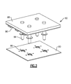
- Figure 2 shows a duct 80 which is provided with a plurality of holes 86 to receive studs or bolts 84 from a combined CMC panel and backing liner 82.
- the panel 88 will face hot products of combustion in an engine such as the Figure 1 engine, while the duct 80 is a housing structure within the gas turbine engine.
- the combined panel and liner 82 includes a ceramic matrix composite panel 88 and a backing metal liner 90.
- the combination 82 can be located in a combustor, an exhaust nozzle, in an augmentor, or in any other location within a gas turbine engine which sees hot products of combustion.
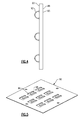
- Figure 3 shows the combination 82.
- the panel 88 has rings 92 which are mounted on spring fingers 94 fixed to the liner 90.
- the spring fingers 94 provide a bias force biasing the ceramic matrix composite panel 88 onto the liner 90 and securely holding it, but not providing a force high enough to fracture the ceramic matrix composite material.
- Figure 4 shows a detail of the panel 88 and the rings 92 which extend away from one face of the panel 88. It should be understood the rings 92 extend away from a face 93 which is on an opposed side of the panel 88 relative to a face 95 which will face the hot products of combustion.
- Figure 5 shows a detail of the liner 90. As shown, there are a plurality of apertures 96, each defining a C-shaped opening around an intermediate finger 98.
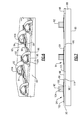
- Figure 6 shows the rings 92 received outwardly of a ring 104 on a spring finger 94. The spring finger 94 sits on the liner finger 98.
- the spring finger 94 has a remote end 102 which is attached, such as by welding, to the liner 90, preferably, at a location beyond the ends of the aperture 96.
- An opposed end 99 of the finger is spaced by a central web 100 which extends away from an inner face 101 of the liner 90, such that there is a bow in the spring 94.
- the remote end 99 is free to slide along the finger 98 at the opposed end.
- a portion of the slot or aperture 96 is forward of a forward end 111 of the finger 98.
- the ring 104 When the spring ring 104 is received within the extending member or panel ring 92, the ring 104 is biased downwardly toward the face 101 of the liner 90. This creates a bias force biasing the ring 92 and, hence, the liner 88 in a direction which is upward in Figure 7 , or away from the hot products of combustion which will be toward the face 95 of the panel 88.
- Figure 8A shows a first step in assembling the panel 88 to the liner 90.
- the ring 92 is inserted through the aperture 96. In this position, the ring 104 is free.
- the rings 92 are then moved to then be over the ring 104 and bias the ring 104 downwardly as shown in Figure 7 . This creates a bias force as described above.
- Figure 8B shows the panel 88 being the portion that is actually moved to have ring 92 slide onto ring 94, it should be understood that the opposite direction of movement, with the panel 90 being moved such that ring 104 is moved within ring 92 would also be possible. Either direction would be met by the description of sliding the ring 92 onto the ring 104.
- Figure 9 shows a detail of the spring 94.
- chamfers 106 and 108 may be formed at ends of the ring 104 to facilitate the sliding of the ring 92 into rings 104.
- there is a circumferentially central slot 105 creating two discontinuous sides which assists in creating a spring force from the rings 104 to be transferred into the central web 100 and the end 99.
- the combined liner and panel 82 for use in a gas turbine engine has a ceramic matrix composite panel 88 having a plurality of extending members or rings 92 extending away from a face 95 of ceramic matrix composite panel 88 which will face hot products of combustion.
- the liner 90 includes a plurality of spring members 94 that apply a bias force biasing the extending members 92.
- the spring members 94 bias the extending members 92 on the panel in a direction away from the face 95 of the panel which will face the hot products of combustion. While rings 92 are disclosed, other extending members may be utilized.
Landscapes
- Engineering & Computer Science (AREA)
- Chemical & Material Sciences (AREA)
- Combustion & Propulsion (AREA)
- Mechanical Engineering (AREA)
- General Engineering & Computer Science (AREA)
- Ceramic Engineering (AREA)
- Turbine Rotor Nozzle Sealing (AREA)
Applications Claiming Priority (1)
| Application Number | Priority Date | Filing Date | Title |
|---|---|---|---|
| US201461925732P | 2014-01-10 | 2014-01-10 |
Publications (2)
| Publication Number | Publication Date |
|---|---|
| EP2894403A1 true EP2894403A1 (fr) | 2015-07-15 |
| EP2894403B1 EP2894403B1 (fr) | 2017-03-08 |
Family
ID=52338989
Family Applications (1)
| Application Number | Title | Priority Date | Filing Date |
|---|---|---|---|
| EP15150263.0A Active EP2894403B1 (fr) | 2014-01-10 | 2015-01-07 | Fixation d'un panneau composite à matrice céramique sur un revêtement |
Country Status (2)
| Country | Link |
|---|---|
| US (2) | US9890953B2 (fr) |
| EP (1) | EP2894403B1 (fr) |
Families Citing this family (1)
| Publication number | Priority date | Publication date | Assignee | Title |
|---|---|---|---|---|
| DE102019200593A1 (de) * | 2019-01-17 | 2020-07-23 | Siemens Aktiengesellschaft | Brennkammer |
Citations (4)
| Publication number | Priority date | Publication date | Assignee | Title |
|---|---|---|---|---|
| US4848089A (en) * | 1988-02-18 | 1989-07-18 | Avco Corporation | Combustor attachment device |
| US4944151A (en) * | 1988-09-26 | 1990-07-31 | Avco Corporation | Segmented combustor panel |
| US5201799A (en) * | 1991-05-20 | 1993-04-13 | United Technologies Corporation | Clip attachment for combustor panel |
| US5265411A (en) * | 1992-10-05 | 1993-11-30 | United Technologies Corporation | Attachment clip |
Family Cites Families (20)
| Publication number | Priority date | Publication date | Assignee | Title |
|---|---|---|---|---|
| US4512159A (en) * | 1984-04-02 | 1985-04-23 | United Technologies Corporation | Clip attachment |
| US4748806A (en) * | 1985-07-03 | 1988-06-07 | United Technologies Corporation | Attachment means |
| US5553455A (en) * | 1987-12-21 | 1996-09-10 | United Technologies Corporation | Hybrid ceramic article |
| FR2646880A1 (fr) * | 1989-05-11 | 1990-11-16 | Snecma | Chemise de protection thermique pour canal de post-combustion ou de transition d'un turboreacteur |
| US5337583A (en) * | 1992-08-24 | 1994-08-16 | United Technologies Corporation | Replaceable clip |
| IL109085A (en) * | 1993-04-05 | 1997-08-14 | Gen Electric | Nozzle seal assembly with removable baseplate |
| US5592814A (en) * | 1994-12-21 | 1997-01-14 | United Technologies Corporation | Attaching brittle composite structures in gas turbine engines for resiliently accommodating thermal expansion |
| US5755093A (en) * | 1995-05-01 | 1998-05-26 | United Technologies Corporation | Forced air cooled gas turbine exhaust liner |
| EP1381811A1 (fr) * | 2001-04-27 | 2004-01-21 | Siemens Aktiengesellschaft | Chambre de combustion, en particulier d'une turbine a gaz |
| DE10155420A1 (de) * | 2001-11-12 | 2003-05-22 | Rolls Royce Deutschland | Hitzeschildanordnung mit Dichtungselement |
| EP1312865A1 (fr) * | 2001-11-15 | 2003-05-21 | Siemens Aktiengesellschaft | Chambre de combustion annulaire de turbine à gaz |
| US7237389B2 (en) * | 2004-11-18 | 2007-07-03 | Siemens Power Generation, Inc. | Attachment system for ceramic combustor liner |
| US7647779B2 (en) | 2005-04-27 | 2010-01-19 | United Technologies Corporation | Compliant metal support for ceramic combustor liner in a gas turbine engine |
| US7546743B2 (en) | 2005-10-12 | 2009-06-16 | General Electric Company | Bolting configuration for joining ceramic combustor liner to metal mounting attachments |
| US7874059B2 (en) | 2006-01-12 | 2011-01-25 | Siemens Energy, Inc. | Attachment for ceramic matrix composite component |
| US8607577B2 (en) * | 2009-11-24 | 2013-12-17 | United Technologies Corporation | Attaching ceramic matrix composite to high temperature gas turbine structure |
| US20110146944A1 (en) * | 2009-12-22 | 2011-06-23 | John Hand | Heat Exchanger Mounting Assembly |
| US9249732B2 (en) * | 2012-09-28 | 2016-02-02 | United Technologies Corporation | Panel support hanger for a turbine engine |
| US9322334B2 (en) * | 2012-10-23 | 2016-04-26 | General Electric Company | Deformable mounting assembly |
| US9657687B2 (en) * | 2013-09-12 | 2017-05-23 | Powerbreather International Gmbh | Exhaust duct liner rod hanger |
-
2015
- 2015-01-02 US US14/588,471 patent/US9890953B2/en active Active
- 2015-01-07 EP EP15150263.0A patent/EP2894403B1/fr active Active
-
2017
- 2017-11-02 US US15/801,557 patent/US10823406B2/en active Active
Patent Citations (4)
| Publication number | Priority date | Publication date | Assignee | Title |
|---|---|---|---|---|
| US4848089A (en) * | 1988-02-18 | 1989-07-18 | Avco Corporation | Combustor attachment device |
| US4944151A (en) * | 1988-09-26 | 1990-07-31 | Avco Corporation | Segmented combustor panel |
| US5201799A (en) * | 1991-05-20 | 1993-04-13 | United Technologies Corporation | Clip attachment for combustor panel |
| US5265411A (en) * | 1992-10-05 | 1993-11-30 | United Technologies Corporation | Attachment clip |
Also Published As
| Publication number | Publication date |
|---|---|
| US20150345790A1 (en) | 2015-12-03 |
| US9890953B2 (en) | 2018-02-13 |
| EP2894403B1 (fr) | 2017-03-08 |
| US20180156456A1 (en) | 2018-06-07 |
| US10823406B2 (en) | 2020-11-03 |
Similar Documents
| Publication | Publication Date | Title |
|---|---|---|
| EP2900957B1 (fr) | Vanne d'antigivrage de nacelle servant de vanne de prélèvement de stabilité de compresseur pendant un démarrage | |
| EP3000979A1 (fr) | Segment d'arc d'aube pincé ayant des caractéristiques de transmission de charge | |
| EP3111057B1 (fr) | Raccordement de barre d'accouplement pour un cadre de turbine intermédiaire | |
| US10132187B2 (en) | Clearance control assembly | |
| EP2985419B1 (fr) | Ensemble de pales de turbomachines avec étanchéités de pied d'aube | |
| EP3022419B1 (fr) | Bords arrondis pour un écran thermique de chambre de combustion | |
| EP3323979B1 (fr) | Profil aérodynamique avec panneau présentant un joint périphérique | |
| EP3608514B1 (fr) | Support structural pour ensemble de joints d'air extérieur d'aube | |
| EP2904252B1 (fr) | Aube directrice statique à canaux internes creux | |
| US20140147271A1 (en) | Pressure Seal With Non-Metallic Wear Surfaces | |
| EP3008291B1 (fr) | Aube de turbine à épaisseur de paroi non uniforme | |
| EP3102808B1 (fr) | Tube composite de fluide de refroidissement d'une turbine à gaz | |
| EP3101236B1 (fr) | Joints de bord de fuite de plate-forme | |
| EP3287621A1 (fr) | Échangeur de chaleur pour moteur à turbine à gaz comprenant un support amortisseur | |
| US10823406B2 (en) | Attachment of ceramic matrix composite panel to liner | |
| US10309251B2 (en) | Interlocking rotor assembly with thermal shield | |
| US11286797B2 (en) | Gas turbine engine stator vane base shape | |
| EP3564495A1 (fr) | Composant d'échappement de moteur à turbine à gaz | |
| EP3597870B1 (fr) | Turbine à gaz | |
| EP3620611A1 (fr) | Support de joint d'air externe de lame unifié et plateforme de pale | |
| EP3599347B1 (fr) | Bloc de fixation pour joint d'air externe de lame assurant un refroidissement par impact | |
| EP3181869A1 (fr) | Refroidissement de diamètre interne de compresseur | |
| EP3179034A1 (fr) | Air de refroidissement à plusieurs sources pour une turbine |
Legal Events
| Date | Code | Title | Description |
|---|---|---|---|
| PUAI | Public reference made under article 153(3) epc to a published international application that has entered the european phase |
Free format text: ORIGINAL CODE: 0009012 |
|
| 17P | Request for examination filed |
Effective date: 20150107 |
|
| AK | Designated contracting states |
Kind code of ref document: A1 Designated state(s): AL AT BE BG CH CY CZ DE DK EE ES FI FR GB GR HR HU IE IS IT LI LT LU LV MC MK MT NL NO PL PT RO RS SE SI SK SM TR |
|
| AX | Request for extension of the european patent |
Extension state: BA ME |
|
| R17P | Request for examination filed (corrected) |
Effective date: 20160115 |
|
| RBV | Designated contracting states (corrected) |
Designated state(s): AL AT BE BG CH CY CZ DE DK EE ES FI FR GB GR HR HU IE IS IT LI LT LU LV MC MK MT NL NO PL PT RO RS SE SI SK SM TR |
|
| GRAP | Despatch of communication of intention to grant a patent |
Free format text: ORIGINAL CODE: EPIDOSNIGR1 |
|
| RIC1 | Information provided on ipc code assigned before grant |
Ipc: F23M 5/04 20060101AFI20160329BHEP Ipc: F23R 3/00 20060101ALI20160329BHEP |
|
| INTG | Intention to grant announced |
Effective date: 20160428 |
|
| GRAS | Grant fee paid |
Free format text: ORIGINAL CODE: EPIDOSNIGR3 |
|
| GRAJ | Information related to disapproval of communication of intention to grant by the applicant or resumption of examination proceedings by the epo deleted |
Free format text: ORIGINAL CODE: EPIDOSDIGR1 |
|
| GRAL | Information related to payment of fee for publishing/printing deleted |
Free format text: ORIGINAL CODE: EPIDOSDIGR3 |
|
| INTC | Intention to grant announced (deleted) | ||
| RAP1 | Party data changed (applicant data changed or rights of an application transferred) |
Owner name: UNITED TECHNOLOGIES CORPORATION |
|
| GRAR | Information related to intention to grant a patent recorded |
Free format text: ORIGINAL CODE: EPIDOSNIGR71 |
|
| INTG | Intention to grant announced |
Effective date: 20161129 |
|
| GRAA | (expected) grant |
Free format text: ORIGINAL CODE: 0009210 |
|
| AK | Designated contracting states |
Kind code of ref document: B1 Designated state(s): AL AT BE BG CH CY CZ DE DK EE ES FI FR GB GR HR HU IE IS IT LI LT LU LV MC MK MT NL NO PL PT RO RS SE SI SK SM TR |
|
| REG | Reference to a national code |
Ref country code: GB Ref legal event code: FG4D |
|
| REG | Reference to a national code |
Ref country code: CH Ref legal event code: EP Ref country code: AT Ref legal event code: REF Ref document number: 873871 Country of ref document: AT Kind code of ref document: T Effective date: 20170315 |
|
| REG | Reference to a national code |
Ref country code: IE Ref legal event code: FG4D |
|
| REG | Reference to a national code |
Ref country code: DE Ref legal event code: R096 Ref document number: 602015001685 Country of ref document: DE |
|
| REG | Reference to a national code |
Ref country code: LT Ref legal event code: MG4D |
|
| REG | Reference to a national code |
Ref country code: NL Ref legal event code: MP Effective date: 20170308 Ref country code: DE Ref legal event code: R082 Ref document number: 602015001685 Country of ref document: DE Representative=s name: SCHMITT-NILSON SCHRAUD WAIBEL WOHLFROM PATENTA, DE |
|
| PG25 | Lapsed in a contracting state [announced via postgrant information from national office to epo] |
Ref country code: LT Free format text: LAPSE BECAUSE OF FAILURE TO SUBMIT A TRANSLATION OF THE DESCRIPTION OR TO PAY THE FEE WITHIN THE PRESCRIBED TIME-LIMIT Effective date: 20170308 Ref country code: FI Free format text: LAPSE BECAUSE OF FAILURE TO SUBMIT A TRANSLATION OF THE DESCRIPTION OR TO PAY THE FEE WITHIN THE PRESCRIBED TIME-LIMIT Effective date: 20170308 Ref country code: GR Free format text: LAPSE BECAUSE OF FAILURE TO SUBMIT A TRANSLATION OF THE DESCRIPTION OR TO PAY THE FEE WITHIN THE PRESCRIBED TIME-LIMIT Effective date: 20170609 Ref country code: NO Free format text: LAPSE BECAUSE OF FAILURE TO SUBMIT A TRANSLATION OF THE DESCRIPTION OR TO PAY THE FEE WITHIN THE PRESCRIBED TIME-LIMIT Effective date: 20170608 Ref country code: HR Free format text: LAPSE BECAUSE OF FAILURE TO SUBMIT A TRANSLATION OF THE DESCRIPTION OR TO PAY THE FEE WITHIN THE PRESCRIBED TIME-LIMIT Effective date: 20170308 |
|
| REG | Reference to a national code |
Ref country code: AT Ref legal event code: MK05 Ref document number: 873871 Country of ref document: AT Kind code of ref document: T Effective date: 20170308 |
|
| PG25 | Lapsed in a contracting state [announced via postgrant information from national office to epo] |
Ref country code: ES Free format text: LAPSE BECAUSE OF FAILURE TO SUBMIT A TRANSLATION OF THE DESCRIPTION OR TO PAY THE FEE WITHIN THE PRESCRIBED TIME-LIMIT Effective date: 20170308 Ref country code: LV Free format text: LAPSE BECAUSE OF FAILURE TO SUBMIT A TRANSLATION OF THE DESCRIPTION OR TO PAY THE FEE WITHIN THE PRESCRIBED TIME-LIMIT Effective date: 20170308 Ref country code: RS Free format text: LAPSE BECAUSE OF FAILURE TO SUBMIT A TRANSLATION OF THE DESCRIPTION OR TO PAY THE FEE WITHIN THE PRESCRIBED TIME-LIMIT Effective date: 20170308 Ref country code: BG Free format text: LAPSE BECAUSE OF FAILURE TO SUBMIT A TRANSLATION OF THE DESCRIPTION OR TO PAY THE FEE WITHIN THE PRESCRIBED TIME-LIMIT Effective date: 20170608 Ref country code: SE Free format text: LAPSE BECAUSE OF FAILURE TO SUBMIT A TRANSLATION OF THE DESCRIPTION OR TO PAY THE FEE WITHIN THE PRESCRIBED TIME-LIMIT Effective date: 20170308 |
|
| PG25 | Lapsed in a contracting state [announced via postgrant information from national office to epo] |
Ref country code: NL Free format text: LAPSE BECAUSE OF FAILURE TO SUBMIT A TRANSLATION OF THE DESCRIPTION OR TO PAY THE FEE WITHIN THE PRESCRIBED TIME-LIMIT Effective date: 20170308 |
|
| PG25 | Lapsed in a contracting state [announced via postgrant information from national office to epo] |
Ref country code: AT Free format text: LAPSE BECAUSE OF FAILURE TO SUBMIT A TRANSLATION OF THE DESCRIPTION OR TO PAY THE FEE WITHIN THE PRESCRIBED TIME-LIMIT Effective date: 20170308 Ref country code: RO Free format text: LAPSE BECAUSE OF FAILURE TO SUBMIT A TRANSLATION OF THE DESCRIPTION OR TO PAY THE FEE WITHIN THE PRESCRIBED TIME-LIMIT Effective date: 20170308 Ref country code: EE Free format text: LAPSE BECAUSE OF FAILURE TO SUBMIT A TRANSLATION OF THE DESCRIPTION OR TO PAY THE FEE WITHIN THE PRESCRIBED TIME-LIMIT Effective date: 20170308 Ref country code: SK Free format text: LAPSE BECAUSE OF FAILURE TO SUBMIT A TRANSLATION OF THE DESCRIPTION OR TO PAY THE FEE WITHIN THE PRESCRIBED TIME-LIMIT Effective date: 20170308 Ref country code: CZ Free format text: LAPSE BECAUSE OF FAILURE TO SUBMIT A TRANSLATION OF THE DESCRIPTION OR TO PAY THE FEE WITHIN THE PRESCRIBED TIME-LIMIT Effective date: 20170308 |
|
| PG25 | Lapsed in a contracting state [announced via postgrant information from national office to epo] |
Ref country code: PL Free format text: LAPSE BECAUSE OF FAILURE TO SUBMIT A TRANSLATION OF THE DESCRIPTION OR TO PAY THE FEE WITHIN THE PRESCRIBED TIME-LIMIT Effective date: 20170308 Ref country code: PT Free format text: LAPSE BECAUSE OF FAILURE TO SUBMIT A TRANSLATION OF THE DESCRIPTION OR TO PAY THE FEE WITHIN THE PRESCRIBED TIME-LIMIT Effective date: 20170710 Ref country code: IS Free format text: LAPSE BECAUSE OF FAILURE TO SUBMIT A TRANSLATION OF THE DESCRIPTION OR TO PAY THE FEE WITHIN THE PRESCRIBED TIME-LIMIT Effective date: 20170708 Ref country code: SM Free format text: LAPSE BECAUSE OF FAILURE TO SUBMIT A TRANSLATION OF THE DESCRIPTION OR TO PAY THE FEE WITHIN THE PRESCRIBED TIME-LIMIT Effective date: 20170308 |
|
| REG | Reference to a national code |
Ref country code: DE Ref legal event code: R097 Ref document number: 602015001685 Country of ref document: DE |
|
| REG | Reference to a national code |
Ref country code: FR Ref legal event code: PLFP Year of fee payment: 4 |
|
| PLBE | No opposition filed within time limit |
Free format text: ORIGINAL CODE: 0009261 |
|
| STAA | Information on the status of an ep patent application or granted ep patent |
Free format text: STATUS: NO OPPOSITION FILED WITHIN TIME LIMIT |
|
| PG25 | Lapsed in a contracting state [announced via postgrant information from national office to epo] |
Ref country code: DK Free format text: LAPSE BECAUSE OF FAILURE TO SUBMIT A TRANSLATION OF THE DESCRIPTION OR TO PAY THE FEE WITHIN THE PRESCRIBED TIME-LIMIT Effective date: 20170308 |
|
| 26N | No opposition filed |
Effective date: 20171211 |
|
| PG25 | Lapsed in a contracting state [announced via postgrant information from national office to epo] |
Ref country code: IT Free format text: LAPSE BECAUSE OF FAILURE TO SUBMIT A TRANSLATION OF THE DESCRIPTION OR TO PAY THE FEE WITHIN THE PRESCRIBED TIME-LIMIT Effective date: 20170308 Ref country code: SI Free format text: LAPSE BECAUSE OF FAILURE TO SUBMIT A TRANSLATION OF THE DESCRIPTION OR TO PAY THE FEE WITHIN THE PRESCRIBED TIME-LIMIT Effective date: 20170308 |
|
| REG | Reference to a national code |
Ref country code: CH Ref legal event code: PL |
|
| PG25 | Lapsed in a contracting state [announced via postgrant information from national office to epo] |
Ref country code: LU Free format text: LAPSE BECAUSE OF NON-PAYMENT OF DUE FEES Effective date: 20180107 |
|
| REG | Reference to a national code |
Ref country code: IE Ref legal event code: MM4A |
|
| REG | Reference to a national code |
Ref country code: BE Ref legal event code: MM Effective date: 20180131 |
|
| PG25 | Lapsed in a contracting state [announced via postgrant information from national office to epo] |
Ref country code: LI Free format text: LAPSE BECAUSE OF NON-PAYMENT OF DUE FEES Effective date: 20180131 Ref country code: CH Free format text: LAPSE BECAUSE OF NON-PAYMENT OF DUE FEES Effective date: 20180131 Ref country code: BE Free format text: LAPSE BECAUSE OF NON-PAYMENT OF DUE FEES Effective date: 20180131 |
|
| PG25 | Lapsed in a contracting state [announced via postgrant information from national office to epo] |
Ref country code: IE Free format text: LAPSE BECAUSE OF NON-PAYMENT OF DUE FEES Effective date: 20180107 |
|
| PG25 | Lapsed in a contracting state [announced via postgrant information from national office to epo] |
Ref country code: MC Free format text: LAPSE BECAUSE OF FAILURE TO SUBMIT A TRANSLATION OF THE DESCRIPTION OR TO PAY THE FEE WITHIN THE PRESCRIBED TIME-LIMIT Effective date: 20170308 |
|
| PG25 | Lapsed in a contracting state [announced via postgrant information from national office to epo] |
Ref country code: MT Free format text: LAPSE BECAUSE OF NON-PAYMENT OF DUE FEES Effective date: 20180107 |
|
| PG25 | Lapsed in a contracting state [announced via postgrant information from national office to epo] |
Ref country code: TR Free format text: LAPSE BECAUSE OF FAILURE TO SUBMIT A TRANSLATION OF THE DESCRIPTION OR TO PAY THE FEE WITHIN THE PRESCRIBED TIME-LIMIT Effective date: 20170308 |
|
| PG25 | Lapsed in a contracting state [announced via postgrant information from national office to epo] |
Ref country code: CY Free format text: LAPSE BECAUSE OF FAILURE TO SUBMIT A TRANSLATION OF THE DESCRIPTION OR TO PAY THE FEE WITHIN THE PRESCRIBED TIME-LIMIT Effective date: 20170308 Ref country code: HU Free format text: LAPSE BECAUSE OF FAILURE TO SUBMIT A TRANSLATION OF THE DESCRIPTION OR TO PAY THE FEE WITHIN THE PRESCRIBED TIME-LIMIT; INVALID AB INITIO Effective date: 20150107 Ref country code: MK Free format text: LAPSE BECAUSE OF NON-PAYMENT OF DUE FEES Effective date: 20170308 |
|
| PG25 | Lapsed in a contracting state [announced via postgrant information from national office to epo] |
Ref country code: AL Free format text: LAPSE BECAUSE OF FAILURE TO SUBMIT A TRANSLATION OF THE DESCRIPTION OR TO PAY THE FEE WITHIN THE PRESCRIBED TIME-LIMIT Effective date: 20170308 |
|
| REG | Reference to a national code |
Ref country code: DE Ref legal event code: R081 Ref document number: 602015001685 Country of ref document: DE Owner name: RAYTHEON TECHNOLOGIES CORPORATION (N.D.GES.D.S, US Free format text: FORMER OWNER: UNITED TECHNOLOGIES CORPORATION, FARMINGTON, CONN., US Ref country code: DE Ref legal event code: R081 Ref document number: 602015001685 Country of ref document: DE Owner name: RTX CORPORATION (N.D.GES.D. STAATES DELAWARE),, US Free format text: FORMER OWNER: UNITED TECHNOLOGIES CORPORATION, FARMINGTON, CONN., US |
|
| P01 | Opt-out of the competence of the unified patent court (upc) registered |
Effective date: 20230520 |
|
| REG | Reference to a national code |
Ref country code: DE Ref legal event code: R081 Ref document number: 602015001685 Country of ref document: DE Owner name: RTX CORPORATION (N.D.GES.D. STAATES DELAWARE),, US Free format text: FORMER OWNER: RAYTHEON TECHNOLOGIES CORPORATION (N.D.GES.D.STAATES DELAWARE), ARLINGTON, VA, US |
|
| PGFP | Annual fee paid to national office [announced via postgrant information from national office to epo] |
Ref country code: GB Payment date: 20251217 Year of fee payment: 12 |
|
| PGFP | Annual fee paid to national office [announced via postgrant information from national office to epo] |
Ref country code: FR Payment date: 20251217 Year of fee payment: 12 |
|
| PGFP | Annual fee paid to national office [announced via postgrant information from national office to epo] |
Ref country code: DE Payment date: 20251217 Year of fee payment: 12 |