EP3101236B1 - Joints de bord de fuite de plate-forme - Google Patents
Joints de bord de fuite de plate-forme Download PDFInfo
- Publication number
- EP3101236B1 EP3101236B1 EP16171833.3A EP16171833A EP3101236B1 EP 3101236 B1 EP3101236 B1 EP 3101236B1 EP 16171833 A EP16171833 A EP 16171833A EP 3101236 B1 EP3101236 B1 EP 3101236B1
- Authority
- EP
- European Patent Office
- Prior art keywords
- trailing edge
- platform
- blade
- assembly
- platform trailing
- Prior art date
- Legal status (The legal status is an assumption and is not a legal conclusion. Google has not performed a legal analysis and makes no representation as to the accuracy of the status listed.)
- Active
Links
Images


Classifications
-
- F—MECHANICAL ENGINEERING; LIGHTING; HEATING; WEAPONS; BLASTING
- F01—MACHINES OR ENGINES IN GENERAL; ENGINE PLANTS IN GENERAL; STEAM ENGINES
- F01D—NON-POSITIVE DISPLACEMENT MACHINES OR ENGINES, e.g. STEAM TURBINES
- F01D11/00—Preventing or minimising internal leakage of working-fluid, e.g. between stages
- F01D11/005—Sealing means between non relatively rotating elements
- F01D11/006—Sealing the gap between rotor blades or blades and rotor
-
- F—MECHANICAL ENGINEERING; LIGHTING; HEATING; WEAPONS; BLASTING
- F01—MACHINES OR ENGINES IN GENERAL; ENGINE PLANTS IN GENERAL; STEAM ENGINES
- F01D—NON-POSITIVE DISPLACEMENT MACHINES OR ENGINES, e.g. STEAM TURBINES
- F01D11/00—Preventing or minimising internal leakage of working-fluid, e.g. between stages
- F01D11/001—Preventing or minimising internal leakage of working-fluid, e.g. between stages for sealing space between stator blade and rotor
-
- F—MECHANICAL ENGINEERING; LIGHTING; HEATING; WEAPONS; BLASTING
- F01—MACHINES OR ENGINES IN GENERAL; ENGINE PLANTS IN GENERAL; STEAM ENGINES
- F01D—NON-POSITIVE DISPLACEMENT MACHINES OR ENGINES, e.g. STEAM TURBINES
- F01D11/00—Preventing or minimising internal leakage of working-fluid, e.g. between stages
- F01D11/005—Sealing means between non relatively rotating elements
- F01D11/006—Sealing the gap between rotor blades or blades and rotor
- F01D11/008—Sealing the gap between rotor blades or blades and rotor by spacer elements between the blades, e.g. independent interblade platforms
-
- F—MECHANICAL ENGINEERING; LIGHTING; HEATING; WEAPONS; BLASTING
- F01—MACHINES OR ENGINES IN GENERAL; ENGINE PLANTS IN GENERAL; STEAM ENGINES
- F01D—NON-POSITIVE DISPLACEMENT MACHINES OR ENGINES, e.g. STEAM TURBINES
- F01D5/00—Blades; Blade-carrying members; Heating, heat-insulating, cooling or antivibration means on the blades or the members
- F01D5/12—Blades
- F01D5/14—Form or construction
- F01D5/147—Construction, i.e. structural features, e.g. of weight-saving hollow blades
-
- F—MECHANICAL ENGINEERING; LIGHTING; HEATING; WEAPONS; BLASTING
- F01—MACHINES OR ENGINES IN GENERAL; ENGINE PLANTS IN GENERAL; STEAM ENGINES
- F01D—NON-POSITIVE DISPLACEMENT MACHINES OR ENGINES, e.g. STEAM TURBINES
- F01D5/00—Blades; Blade-carrying members; Heating, heat-insulating, cooling or antivibration means on the blades or the members
- F01D5/12—Blades
- F01D5/22—Blade-to-blade connections, e.g. for damping vibrations
- F01D5/225—Blade-to-blade connections, e.g. for damping vibrations by shrouding
-
- F—MECHANICAL ENGINEERING; LIGHTING; HEATING; WEAPONS; BLASTING
- F05—INDEXING SCHEMES RELATING TO ENGINES OR PUMPS IN VARIOUS SUBCLASSES OF CLASSES F01-F04
- F05D—INDEXING SCHEME FOR ASPECTS RELATING TO NON-POSITIVE-DISPLACEMENT MACHINES OR ENGINES, GAS-TURBINES OR JET-PROPULSION PLANTS
- F05D2220/00—Application
- F05D2220/30—Application in turbines
- F05D2220/32—Application in turbines in gas turbines
-
- F—MECHANICAL ENGINEERING; LIGHTING; HEATING; WEAPONS; BLASTING
- F05—INDEXING SCHEMES RELATING TO ENGINES OR PUMPS IN VARIOUS SUBCLASSES OF CLASSES F01-F04
- F05D—INDEXING SCHEME FOR ASPECTS RELATING TO NON-POSITIVE-DISPLACEMENT MACHINES OR ENGINES, GAS-TURBINES OR JET-PROPULSION PLANTS
- F05D2240/00—Components
- F05D2240/55—Seals
-
- F—MECHANICAL ENGINEERING; LIGHTING; HEATING; WEAPONS; BLASTING
- F05—INDEXING SCHEMES RELATING TO ENGINES OR PUMPS IN VARIOUS SUBCLASSES OF CLASSES F01-F04
- F05D—INDEXING SCHEME FOR ASPECTS RELATING TO NON-POSITIVE-DISPLACEMENT MACHINES OR ENGINES, GAS-TURBINES OR JET-PROPULSION PLANTS
- F05D2240/00—Components
- F05D2240/80—Platforms for stationary or moving blades
-
- F—MECHANICAL ENGINEERING; LIGHTING; HEATING; WEAPONS; BLASTING
- F05—INDEXING SCHEMES RELATING TO ENGINES OR PUMPS IN VARIOUS SUBCLASSES OF CLASSES F01-F04
- F05D—INDEXING SCHEME FOR ASPECTS RELATING TO NON-POSITIVE-DISPLACEMENT MACHINES OR ENGINES, GAS-TURBINES OR JET-PROPULSION PLANTS
- F05D2260/00—Function
- F05D2260/94—Functionality given by mechanical stress related aspects such as low cycle fatigue [LCF] of high cycle fatigue [HCF]
- F05D2260/941—Functionality given by mechanical stress related aspects such as low cycle fatigue [LCF] of high cycle fatigue [HCF] particularly aimed at mechanical or thermal stress reduction
-
- F—MECHANICAL ENGINEERING; LIGHTING; HEATING; WEAPONS; BLASTING
- F05—INDEXING SCHEMES RELATING TO ENGINES OR PUMPS IN VARIOUS SUBCLASSES OF CLASSES F01-F04
- F05D—INDEXING SCHEME FOR ASPECTS RELATING TO NON-POSITIVE-DISPLACEMENT MACHINES OR ENGINES, GAS-TURBINES OR JET-PROPULSION PLANTS
- F05D2300/00—Materials; Properties thereof
- F05D2300/10—Metals, alloys or intermetallic compounds
- F05D2300/17—Alloys
- F05D2300/173—Aluminium alloys, e.g. AlCuMgPb
-
- F—MECHANICAL ENGINEERING; LIGHTING; HEATING; WEAPONS; BLASTING
- F05—INDEXING SCHEMES RELATING TO ENGINES OR PUMPS IN VARIOUS SUBCLASSES OF CLASSES F01-F04
- F05D—INDEXING SCHEME FOR ASPECTS RELATING TO NON-POSITIVE-DISPLACEMENT MACHINES OR ENGINES, GAS-TURBINES OR JET-PROPULSION PLANTS
- F05D2300/00—Materials; Properties thereof
- F05D2300/10—Metals, alloys or intermetallic compounds
- F05D2300/17—Alloys
- F05D2300/174—Titanium alloys, e.g. TiAl
-
- F—MECHANICAL ENGINEERING; LIGHTING; HEATING; WEAPONS; BLASTING
- F05—INDEXING SCHEMES RELATING TO ENGINES OR PUMPS IN VARIOUS SUBCLASSES OF CLASSES F01-F04
- F05D—INDEXING SCHEME FOR ASPECTS RELATING TO NON-POSITIVE-DISPLACEMENT MACHINES OR ENGINES, GAS-TURBINES OR JET-PROPULSION PLANTS
- F05D2300/00—Materials; Properties thereof
- F05D2300/10—Metals, alloys or intermetallic compounds
- F05D2300/17—Alloys
- F05D2300/177—Ni - Si alloys
Definitions
- the present disclosure relates to turbomachine seals, more specifically to seals for turbomachine blades.
- EP 0851097 discloses a turbine blade damper and seal that spans a central portion of a gap between adjacent platforms of a plurality of rotor blades extending radially from a rotor disk.
- a further example of a platform trailing edge seal is given by the patent documentation US 5 957 658 A .
- an assembly comprising a plurality of turbomachine blade assemblies and a platform trailing edge seal, the turbomachine blade assemblies each comprising: a blade having a blade platform which defines a platform trailing edge portion; and the platform trailing edge seal extending from the trailing edge portion; characterised in that the platform trailing edge seal comprises an annular or segmented annular body configured to extend into or across an aft portion of a mateface gap defined between a circumferentially adjacent pair of turbomachine blade platforms to minimize flow from entering a blade-vane cavity through the aft portion of the mateface gap, wherein the body is shaped to match the platform trailing edge shape.
- the platform trailing edge seal can be formed integrally with the platform trailing edge. In other embodiments, the platform trailing edge seal can be attached to the platform trailing edge.
- the blade can be located in one of a low pressure compressor, a high pressure compressor, a low pressure turbine, or a high pressure turbine.
- the blade platform can include one or more protrusions for securing the platform trailing edge seal to the blade platform.
- the platform trailing edge seal can be friction fit, thermally fit, and/or expansion fit to the blade platform.
- the assembly can include one or more retaining features attached to the blade platform and configured to retain the platform trailing edge seal to the blade platform.
- a turbomachine includes a turbomachine blade assembly as described above.
- FIG. 2A An illustrative view of an embodiment of a seal 200 and assembly 250 in accordance with the disclosure is shown in Figs. 2A .
- FIGs. 1 and 2A-5C Other embodiments and/or aspects of this disclosure are shown in Figs. 1 and 2A-5C .
- the systems and methods described herein can be used to improve the operating efficiency of a turbomachine.
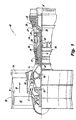
- Fig. 1 schematically illustrates a gas turbine engine 20.
- the gas turbine engine 20 is disclosed herein as a two-spool turbofan that generally incorporates a fan section 22, a compressor section 24, a combustor section 26 and a turbine section 28.
- Alternative engines might include an augmentor section (not shown) among other systems or features.
- the fan section 22 drives air along a bypass flow path B in a bypass duct defined within a nacelle 15, while the compressor section 24 drives air along a core flow path C for compression and communication into the combustor section 26 then expansion through the turbine section 28.
- the exemplary engine 20 generally includes a low speed spool 30 and a high speed spool 32 mounted for rotation about an engine central longitudinal axis A relative to an engine static structure 36 via several bearing systems 38. It should be understood that various bearing systems 38 at various locations may alternatively or additionally be provided and the location of bearing systems 38 may be varied as appropriate to the application.
- the low speed spool 30 generally includes an inner shaft 40 that interconnects a fan 42, a first (or low) pressure compressor 44 and a first (or low) pressure turbine 46.
- the inner shaft 40 is connected to the fan 42 through a speed change mechanism, which in exemplary gas turbine engine 20 is illustrated as a gear system 48 to drive the fan 42 at a lower speed than the low speed spool 30.
- the high speed spool 32 includes an outer shaft 50 that interconnects a second (or high) pressure compressor 52 and a second (or high) pressure turbine 54.
- a combustor 56 is arranged in exemplary gas turbine 20 between the high pressure compressor 52 and the high pressure turbine 54.
- a mid-turbine frame 57 of the engine static structure 36 is arranged generally between the high pressure turbine 54 and the low pressure turbine 46.
- the mid-turbine frame 57 further supports bearing systems 38 in the turbine section 28.
- the inner shaft 40 and the outer shaft 50 are concentric and rotate via bearing systems 38 about the engine central longitudinal axis A which is collinear with their longitudinal axes.
- the core airflow is compressed by the low pressure compressor 44 then the high pressure compressor 52, mixed and burned with fuel in the combustor 56, then expanded over the high pressure turbine 54 and low pressure turbine 46.
- the mid-turbine frame 57 includes airfoils 59 which are in the core airflow path C.
- the turbines 46, 54 rotationally drive the respective low speed spool 30 and high speed spool 32 in response to the expansion.
- gear system 48 may be located aft of combustor section 26 or even aft of turbine section 28, and fan section 22 may be positioned forward or aft of the location of gear system 48.
- the engine 20 in one example is a high-bypass geared aircraft engine,
- the engine 20 bypass ratio is greater than about six (6), with an example embodiment being greater than about ten (10)
- the geared architecture is an epicyclic gear train, such as a planetary gear system or other gear system, with a gear reduction ratio of greater than about 2.3 and the low pressure turbine 46 has a pressure ratio that is greater than about five.
- the engine 20 bypass ratio is greater than about ten (10:1)
- the fan diameter is significantly larger than that of the low pressure compressor 44
- the low pressure turbine 46 has a pressure ratio that is greater than about five (5:1).
- Low pressure turbine 46 pressure ratio is pressure measured prior to inlet of low pressure turbine 46 as related to the pressure at the outlet of the low pressure turbine 46 prior to an exhaust nozzle.
- the geared architecture may be an epicycle gear train, such as a planetary gear system or other gear system, with a gear reduction ratio of greater than about 2.3:1. It should be understood, however, that the above parameters are only exemplary of one embodiment of a geared architecture engine and that the present invention is applicable to other gas turbine engines including direct drive turbofans,
- the fan section 22 of the engine 20 is designed for a particular flight condition -- typically cruise at about 0.8 Mach and about 10.668 m (35.000 ft).
- "Low fan pressure ratio” is the pressure ratio across the fan blade alone, without a Fan Exit Guide Vane 79 (“FEGV”) system.
- the low fan pressure ratio as disclosed herein according to one non-limiting embodiment is less than about 1.45.
- Low corrected fan tip speed is the actual fan tip speed in ft/sec divided by an industry standard temperature correction of [(Tram °R) / (518.7 °R)] ⁇ 0.5.
- the "Low corrected fan tip speed” as disclosed herein according to one non-limiting embodiment is less than about 350,5 m/s (1.150 ft/s.)
- a platform trailing edge seal 200 for a turbomachine blade assembly 250 includes a body 201 configured to extend into an aft portion of a mateface gap 203 defined between a circumferentially adjacent pair of turbomachine blade platforms 253 to minimize flow from entering a blade-vane cavity 301 (e.g., defined between the platform trailing edge 255 and vane platform 303 as shown in Fig. 3 ) through the aft portion of the mateface gap 203.
- the turbomachine blade assembly 250 can include a blade 251 having a blade platform 253 which defines a platform trailing edge portion 255.
- the body 201 of the seal 200 can include at least one of aluminum, titanium, nickel, and/or an alloy thereof. However, it is contemplated that the seal 200 can be made with any other suitable material.
- the body 201 is shaped to match a shape of a platform trailing edge 255.
- the body 201 can be annular (e.g., full hoop). It is contemplated, however, that the body 201 can define a segment of a seal structure (e.g., the seal structure being an annular structure) such that a plurality of the seals 200 can be disposed together to form an entire seal structure.
- the platform trailing edge seal 200 can be formed integrally with the platform trailing edge 255.
- each seal 200 forms a segment of a seal structure (e.g., and annular structure) such that when a plurality of blade assemblies 250 are placed adjacent to each other each seal 200 reaches across the aft mateface gap 203 and partially into the adjacent blade platform 253 of the adjacent blade assembly 250.
- the platform trailing edge seal 200 can be attached to the platform trailing edge 255 as a separate piece in any suitable manner.
- the blade platform 253 can include one or more protrusions for securing the platform trailing edge seal 200 to the blade platform 253.
- the platform trailing edge seal 200 can be friction fit, thermally fit, and/or expansion fit to the blade platform 253.
- the assembly 250 can include one or more retaining features 401 (e.g., a clip) attached to the blade platform 253 at the platform trailing edge 255 that are configured to retain the platform trailing edge seal 200 to the blade platform 253.
- the seal 200 disposed under the platform trailing edge 255 can prevent hot gas from being ingested into the mateface gap 203 between the blade platforms 253.
- the seal 200 separates the relatively high gaspath pressure just above the mateface gap 203 from the relatively low gaspath pressure just below the mateface gap 203 in the blade-vane cavity 301 which decreases component temperatures and increases lifespan of the components. Additionally, some of the cooling flow that would traditionally be used to protect and cool this region would not be necessary, thus improving thrust specific fuel consumption.
- the seal 200 can be utilized in a low pressure compressor, high pressure compressor, low pressure turbine, or high pressure turbine. However, it is contemplated that embodiments of a seal 200 as described herein can be utilized in any suitable portion of a turbomachine, for example. While the above seal 200 is disclosed as being configured for use with a trailing edge of a blade platform, it is contemplated that the seal 200 can be configured for use with a trailing edge and/or leading edge of a blade and/or vane platform to minimize undesired flow between adjacent blade platforms or adjacent vane platforms.
Landscapes
- Engineering & Computer Science (AREA)
- Mechanical Engineering (AREA)
- General Engineering & Computer Science (AREA)
- Architecture (AREA)
- Structures Of Non-Positive Displacement Pumps (AREA)
Claims (7)
- Ensemble comprenant une pluralité d'ensembles d'aube de turbomachine (250) et un joint de bord de fuite de plateforme (200 ; 500), les ensembles d'aube de turbomachine comprenant chacun :une aube (251) ayant une plateforme d'aube (253) qui définit une partie de bord de fuite de plateforme (255) ; et le joint de bord de fuite de plateforme s'étendant à partir de la partie de bord de fuite ;caractérisé en ce que le joint de bord de fuite de plateforme comprend un corps annulaire ou annulaire segmenté (201) configuré pour s'étendre dans ou sur une partie arrière d'un espace de face d'accouplement (203) défini entre une paire adjacente de façon circonférentielle de plateformes d'aube de turbomachine pour réduire au minimum l'entrée d'un écoulement dans une cavité aube/pale (301) à travers la partie arrière de l'espace de face d'accouplement, dans lequel le corps (201) est formé pour correspondre à la forme de bord de fuite de plateforme (255).
- Ensemble selon la revendication 1, dans lequel le joint de bord de fuite de plateforme (200) est formé d'un seul tenant avec le bord de fuite de plateforme (255).
- Ensemble selon la revendication 1 ou 2, dans lequel le joint de bord de fuite de plateforme (200) est fixé au bord de fuite de plateforme (255).
- Ensemble selon l'une quelconque des revendications 1 à 3, dans lequel l'aube (251) est située dans l'un(e) d'un compresseur basse pression (44), d'un compresseur haute pression (52), d'une turbine basse pression (46) ou d'une turbine haute pression (54).
- Ensemble selon l'une quelconque des revendications 1 à 4, dans lequel le joint de bord de fuite de plateforme (200) est en ajustement serré, thermique ou par expansion avec la plateforme d'aube (253).
- Ensemble selon l'une quelconque des revendications 1 à 5, incluant en outre un ou plusieurs éléments de retenue (401) fixés à la plateforme d'aube (253) et configurés pour retenir le joint de bord de fuite de plateforme (200) sur la plateforme d'aube.
- Turbomachine, comprenant :
l'ensemble selon l'une quelconque des revendications 1 à 6.
Applications Claiming Priority (1)
| Application Number | Priority Date | Filing Date | Title |
|---|---|---|---|
| US14/726,722 US10196915B2 (en) | 2015-06-01 | 2015-06-01 | Trailing edge platform seals |
Publications (2)
| Publication Number | Publication Date |
|---|---|
| EP3101236A1 EP3101236A1 (fr) | 2016-12-07 |
| EP3101236B1 true EP3101236B1 (fr) | 2020-01-15 |
Family
ID=56081429
Family Applications (1)
| Application Number | Title | Priority Date | Filing Date |
|---|---|---|---|
| EP16171833.3A Active EP3101236B1 (fr) | 2015-06-01 | 2016-05-27 | Joints de bord de fuite de plate-forme |
Country Status (2)
| Country | Link |
|---|---|
| US (1) | US10196915B2 (fr) |
| EP (1) | EP3101236B1 (fr) |
Families Citing this family (3)
| Publication number | Priority date | Publication date | Assignee | Title |
|---|---|---|---|---|
| US10753212B2 (en) * | 2017-08-23 | 2020-08-25 | Doosan Heavy Industries & Construction Co., Ltd | Turbine blade, turbine, and gas turbine having the same |
| FR3107301B1 (fr) * | 2020-02-19 | 2022-03-11 | Safran Aircraft Engines | aube pour roue aubagée mobile de turbomachine d’aéronef comprenant un becquet d’étanchéité à section évolutive optimisée |
| US20240271537A1 (en) * | 2023-02-14 | 2024-08-15 | Raytheon Technologies Corporation | Machinable coating for damping |
Citations (1)
| Publication number | Priority date | Publication date | Assignee | Title |
|---|---|---|---|---|
| US5957658A (en) * | 1997-04-24 | 1999-09-28 | United Technologies Corporation | Fan blade interplatform seal |
Family Cites Families (13)
| Publication number | Priority date | Publication date | Assignee | Title |
|---|---|---|---|---|
| US4580946A (en) * | 1984-11-26 | 1986-04-08 | General Electric Company | Fan blade platform seal |
| US4872810A (en) * | 1988-12-14 | 1989-10-10 | United Technologies Corporation | Turbine rotor retention system |
| US5513955A (en) * | 1994-12-14 | 1996-05-07 | United Technologies Corporation | Turbine engine rotor blade platform seal |
| US5785499A (en) | 1996-12-24 | 1998-07-28 | United Technologies Corporation | Turbine blade damper and seal |
| US6171058B1 (en) * | 1999-04-01 | 2001-01-09 | General Electric Company | Self retaining blade damper |
| DE50211431D1 (de) * | 2001-09-25 | 2008-02-07 | Alstom Technology Ltd | Dichtungsanordnung zur dichtspaltreduzierung innerhalb einer strömungsrotationsmaschine |
| US6887039B2 (en) | 2002-07-10 | 2005-05-03 | Mitsubishi Heavy Industries, Ltd. | Stationary blade in gas turbine and gas turbine comprising the same |
| US7762780B2 (en) * | 2007-01-25 | 2010-07-27 | Siemens Energy, Inc. | Blade assembly in a combustion turbo-machine providing reduced concentration of mechanical stress and a seal between adjacent assemblies |
| US8011892B2 (en) * | 2007-06-28 | 2011-09-06 | United Technologies Corporation | Turbine blade nested seal and damper assembly |
| EP2093381A1 (fr) | 2008-02-25 | 2009-08-26 | Siemens Aktiengesellschaft | Aube rotorique ou statorique de turbine à plateforme refroidie |
| US8820754B2 (en) * | 2010-06-11 | 2014-09-02 | Siemens Energy, Inc. | Turbine blade seal assembly |
| EP2679770A1 (fr) | 2012-06-26 | 2014-01-01 | Siemens Aktiengesellschaft | Bande d'étanchéité pour plate-forme de turbine à gaz |
| EP3044420B1 (fr) * | 2013-09-11 | 2024-07-03 | General Electric Company | Architecture de nappes pour une plate-forme intégrée et éléments de retenue d'amortisseur dans des aubes de turbine en composite à matrice céramique |
-
2015
- 2015-06-01 US US14/726,722 patent/US10196915B2/en active Active
-
2016
- 2016-05-27 EP EP16171833.3A patent/EP3101236B1/fr active Active
Patent Citations (1)
| Publication number | Priority date | Publication date | Assignee | Title |
|---|---|---|---|---|
| US5957658A (en) * | 1997-04-24 | 1999-09-28 | United Technologies Corporation | Fan blade interplatform seal |
Also Published As
| Publication number | Publication date |
|---|---|
| EP3101236A1 (fr) | 2016-12-07 |
| US10196915B2 (en) | 2019-02-05 |
| US20160348525A1 (en) | 2016-12-01 |
Similar Documents
| Publication | Publication Date | Title |
|---|---|---|
| EP3064711B1 (fr) | Composant pour un moteur à turbine à gaz, moteur à turbine à gaz et procédé de formation d'aube associés | |
| EP2952680B1 (fr) | Section de turbine isolée thermiquement pour un moteur à turbine à gaz | |
| EP3093445B1 (fr) | Aube statorique d'une turbine á gaz et procédé de fabrication associé | |
| EP3112606B1 (fr) | Joint pour moteur de turbine à gaz | |
| US20160169004A1 (en) | Cooling passages for gas turbine engine component | |
| US10753220B2 (en) | Gas turbine engine component | |
| EP3056680B1 (fr) | Systèmes d'air de fuite pour turbomachines | |
| EP3061910A1 (fr) | Surface portante de moteur à turbine à gaz et procédé de fabrication correspondant | |
| EP2985419B1 (fr) | Ensemble de pales de turbomachines avec étanchéités de pied d'aube | |
| EP3000968B1 (fr) | Ensemble de disque de rotor pour moteur à turbine à gaz et procédé | |
| EP3095971A1 (fr) | Ensemble support pour moteur à turbine à gaz | |
| EP3101236B1 (fr) | Joints de bord de fuite de plate-forme | |
| US10746033B2 (en) | Gas turbine engine component | |
| EP2947268B1 (fr) | Bouclier thermique de rotor pour une dent de rotor de moteur à tubrine à gaz | |
| US20180080335A1 (en) | Gas turbine engine sealing arrangement | |
| US10378453B2 (en) | Method and assembly for reducing secondary heat in a gas turbine engine | |
| EP2927429B1 (fr) | Composant de moteur à turbine à gaz avec nervure de séparation de flux | |
| EP2904217B1 (fr) | Aube directrice et moteur à turbine à gaz associé | |
| US10030530B2 (en) | Reversible blade rotor seal | |
| EP3597870B1 (fr) | Turbine à gaz | |
| EP3181828A1 (fr) | Joint d'air extérieur d'aube doté de bouclier d'air intégré | |
| EP3109403B1 (fr) | Joint de rotor à lame réversible avec des saillies | |
| EP2885503B1 (fr) | Rotor aubagé intégralement | |
| EP3392472B1 (fr) | Section de compresseur pour un moteur à turbine à gaz, moteur à turbine à gaz et procédé de fonctionnement d'une section de compresseur dans un moteur à turbine à gaz, associés |
Legal Events
| Date | Code | Title | Description |
|---|---|---|---|
| PUAI | Public reference made under article 153(3) epc to a published international application that has entered the european phase |
Free format text: ORIGINAL CODE: 0009012 |
|
| STAA | Information on the status of an ep patent application or granted ep patent |
Free format text: STATUS: THE APPLICATION HAS BEEN PUBLISHED |
|
| AK | Designated contracting states |
Kind code of ref document: A1 Designated state(s): AL AT BE BG CH CY CZ DE DK EE ES FI FR GB GR HR HU IE IS IT LI LT LU LV MC MK MT NL NO PL PT RO RS SE SI SK SM TR |
|
| AX | Request for extension of the european patent |
Extension state: BA ME |
|
| STAA | Information on the status of an ep patent application or granted ep patent |
Free format text: STATUS: REQUEST FOR EXAMINATION WAS MADE |
|
| 17P | Request for examination filed |
Effective date: 20170607 |
|
| RBV | Designated contracting states (corrected) |
Designated state(s): AL AT BE BG CH CY CZ DE DK EE ES FI FR GB GR HR HU IE IS IT LI LT LU LV MC MK MT NL NO PL PT RO RS SE SI SK SM TR |
|
| STAA | Information on the status of an ep patent application or granted ep patent |
Free format text: STATUS: EXAMINATION IS IN PROGRESS |
|
| 17Q | First examination report despatched |
Effective date: 20180914 |
|
| GRAP | Despatch of communication of intention to grant a patent |
Free format text: ORIGINAL CODE: EPIDOSNIGR1 |
|
| STAA | Information on the status of an ep patent application or granted ep patent |
Free format text: STATUS: GRANT OF PATENT IS INTENDED |
|
| INTG | Intention to grant announced |
Effective date: 20190806 |
|
| GRAS | Grant fee paid |
Free format text: ORIGINAL CODE: EPIDOSNIGR3 |
|
| GRAA | (expected) grant |
Free format text: ORIGINAL CODE: 0009210 |
|
| STAA | Information on the status of an ep patent application or granted ep patent |
Free format text: STATUS: THE PATENT HAS BEEN GRANTED |
|
| AK | Designated contracting states |
Kind code of ref document: B1 Designated state(s): AL AT BE BG CH CY CZ DE DK EE ES FI FR GB GR HR HU IE IS IT LI LT LU LV MC MK MT NL NO PL PT RO RS SE SI SK SM TR |
|
| REG | Reference to a national code |
Ref country code: CH Ref legal event code: EP Ref country code: GB Ref legal event code: FG4D |
|
| REG | Reference to a national code |
Ref country code: IE Ref legal event code: FG4D |
|
| REG | Reference to a national code |
Ref country code: DE Ref legal event code: R096 Ref document number: 602016028171 Country of ref document: DE |
|
| REG | Reference to a national code |
Ref country code: AT Ref legal event code: REF Ref document number: 1225318 Country of ref document: AT Kind code of ref document: T Effective date: 20200215 |
|
| REG | Reference to a national code |
Ref country code: NL Ref legal event code: MP Effective date: 20200115 |
|
| REG | Reference to a national code |
Ref country code: LT Ref legal event code: MG4D |
|
| PG25 | Lapsed in a contracting state [announced via postgrant information from national office to epo] |
Ref country code: RS Free format text: LAPSE BECAUSE OF FAILURE TO SUBMIT A TRANSLATION OF THE DESCRIPTION OR TO PAY THE FEE WITHIN THE PRESCRIBED TIME-LIMIT Effective date: 20200115 Ref country code: NO Free format text: LAPSE BECAUSE OF FAILURE TO SUBMIT A TRANSLATION OF THE DESCRIPTION OR TO PAY THE FEE WITHIN THE PRESCRIBED TIME-LIMIT Effective date: 20200415 Ref country code: PT Free format text: LAPSE BECAUSE OF FAILURE TO SUBMIT A TRANSLATION OF THE DESCRIPTION OR TO PAY THE FEE WITHIN THE PRESCRIBED TIME-LIMIT Effective date: 20200607 Ref country code: FI Free format text: LAPSE BECAUSE OF FAILURE TO SUBMIT A TRANSLATION OF THE DESCRIPTION OR TO PAY THE FEE WITHIN THE PRESCRIBED TIME-LIMIT Effective date: 20200115 Ref country code: NL Free format text: LAPSE BECAUSE OF FAILURE TO SUBMIT A TRANSLATION OF THE DESCRIPTION OR TO PAY THE FEE WITHIN THE PRESCRIBED TIME-LIMIT Effective date: 20200115 |
|
| PG25 | Lapsed in a contracting state [announced via postgrant information from national office to epo] |
Ref country code: IS Free format text: LAPSE BECAUSE OF FAILURE TO SUBMIT A TRANSLATION OF THE DESCRIPTION OR TO PAY THE FEE WITHIN THE PRESCRIBED TIME-LIMIT Effective date: 20200515 Ref country code: BG Free format text: LAPSE BECAUSE OF FAILURE TO SUBMIT A TRANSLATION OF THE DESCRIPTION OR TO PAY THE FEE WITHIN THE PRESCRIBED TIME-LIMIT Effective date: 20200415 Ref country code: SE Free format text: LAPSE BECAUSE OF FAILURE TO SUBMIT A TRANSLATION OF THE DESCRIPTION OR TO PAY THE FEE WITHIN THE PRESCRIBED TIME-LIMIT Effective date: 20200115 Ref country code: LV Free format text: LAPSE BECAUSE OF FAILURE TO SUBMIT A TRANSLATION OF THE DESCRIPTION OR TO PAY THE FEE WITHIN THE PRESCRIBED TIME-LIMIT Effective date: 20200115 Ref country code: GR Free format text: LAPSE BECAUSE OF FAILURE TO SUBMIT A TRANSLATION OF THE DESCRIPTION OR TO PAY THE FEE WITHIN THE PRESCRIBED TIME-LIMIT Effective date: 20200416 Ref country code: HR Free format text: LAPSE BECAUSE OF FAILURE TO SUBMIT A TRANSLATION OF THE DESCRIPTION OR TO PAY THE FEE WITHIN THE PRESCRIBED TIME-LIMIT Effective date: 20200115 |
|
| REG | Reference to a national code |
Ref country code: DE Ref legal event code: R097 Ref document number: 602016028171 Country of ref document: DE |
|
| PG25 | Lapsed in a contracting state [announced via postgrant information from national office to epo] |
Ref country code: DK Free format text: LAPSE BECAUSE OF FAILURE TO SUBMIT A TRANSLATION OF THE DESCRIPTION OR TO PAY THE FEE WITHIN THE PRESCRIBED TIME-LIMIT Effective date: 20200115 Ref country code: SM Free format text: LAPSE BECAUSE OF FAILURE TO SUBMIT A TRANSLATION OF THE DESCRIPTION OR TO PAY THE FEE WITHIN THE PRESCRIBED TIME-LIMIT Effective date: 20200115 Ref country code: EE Free format text: LAPSE BECAUSE OF FAILURE TO SUBMIT A TRANSLATION OF THE DESCRIPTION OR TO PAY THE FEE WITHIN THE PRESCRIBED TIME-LIMIT Effective date: 20200115 Ref country code: SK Free format text: LAPSE BECAUSE OF FAILURE TO SUBMIT A TRANSLATION OF THE DESCRIPTION OR TO PAY THE FEE WITHIN THE PRESCRIBED TIME-LIMIT Effective date: 20200115 Ref country code: CZ Free format text: LAPSE BECAUSE OF FAILURE TO SUBMIT A TRANSLATION OF THE DESCRIPTION OR TO PAY THE FEE WITHIN THE PRESCRIBED TIME-LIMIT Effective date: 20200115 Ref country code: ES Free format text: LAPSE BECAUSE OF FAILURE TO SUBMIT A TRANSLATION OF THE DESCRIPTION OR TO PAY THE FEE WITHIN THE PRESCRIBED TIME-LIMIT Effective date: 20200115 Ref country code: RO Free format text: LAPSE BECAUSE OF FAILURE TO SUBMIT A TRANSLATION OF THE DESCRIPTION OR TO PAY THE FEE WITHIN THE PRESCRIBED TIME-LIMIT Effective date: 20200115 Ref country code: LT Free format text: LAPSE BECAUSE OF FAILURE TO SUBMIT A TRANSLATION OF THE DESCRIPTION OR TO PAY THE FEE WITHIN THE PRESCRIBED TIME-LIMIT Effective date: 20200115 |
|
| REG | Reference to a national code |
Ref country code: AT Ref legal event code: MK05 Ref document number: 1225318 Country of ref document: AT Kind code of ref document: T Effective date: 20200115 |
|
| PLBE | No opposition filed within time limit |
Free format text: ORIGINAL CODE: 0009261 |
|
| STAA | Information on the status of an ep patent application or granted ep patent |
Free format text: STATUS: NO OPPOSITION FILED WITHIN TIME LIMIT |
|
| 26N | No opposition filed |
Effective date: 20201016 |
|
| PG25 | Lapsed in a contracting state [announced via postgrant information from national office to epo] |
Ref country code: IT Free format text: LAPSE BECAUSE OF FAILURE TO SUBMIT A TRANSLATION OF THE DESCRIPTION OR TO PAY THE FEE WITHIN THE PRESCRIBED TIME-LIMIT Effective date: 20200115 Ref country code: MC Free format text: LAPSE BECAUSE OF FAILURE TO SUBMIT A TRANSLATION OF THE DESCRIPTION OR TO PAY THE FEE WITHIN THE PRESCRIBED TIME-LIMIT Effective date: 20200115 Ref country code: AT Free format text: LAPSE BECAUSE OF FAILURE TO SUBMIT A TRANSLATION OF THE DESCRIPTION OR TO PAY THE FEE WITHIN THE PRESCRIBED TIME-LIMIT Effective date: 20200115 Ref country code: CH Free format text: LAPSE BECAUSE OF NON-PAYMENT OF DUE FEES Effective date: 20200531 Ref country code: LI Free format text: LAPSE BECAUSE OF NON-PAYMENT OF DUE FEES Effective date: 20200531 |
|
| PG25 | Lapsed in a contracting state [announced via postgrant information from national office to epo] |
Ref country code: SI Free format text: LAPSE BECAUSE OF FAILURE TO SUBMIT A TRANSLATION OF THE DESCRIPTION OR TO PAY THE FEE WITHIN THE PRESCRIBED TIME-LIMIT Effective date: 20200115 Ref country code: PL Free format text: LAPSE BECAUSE OF FAILURE TO SUBMIT A TRANSLATION OF THE DESCRIPTION OR TO PAY THE FEE WITHIN THE PRESCRIBED TIME-LIMIT Effective date: 20200115 |
|
| REG | Reference to a national code |
Ref country code: BE Ref legal event code: MM Effective date: 20200531 |
|
| PG25 | Lapsed in a contracting state [announced via postgrant information from national office to epo] |
Ref country code: LU Free format text: LAPSE BECAUSE OF NON-PAYMENT OF DUE FEES Effective date: 20200527 |
|
| PG25 | Lapsed in a contracting state [announced via postgrant information from national office to epo] |
Ref country code: IE Free format text: LAPSE BECAUSE OF NON-PAYMENT OF DUE FEES Effective date: 20200527 |
|
| PG25 | Lapsed in a contracting state [announced via postgrant information from national office to epo] |
Ref country code: BE Free format text: LAPSE BECAUSE OF NON-PAYMENT OF DUE FEES Effective date: 20200531 |
|
| PG25 | Lapsed in a contracting state [announced via postgrant information from national office to epo] |
Ref country code: TR Free format text: LAPSE BECAUSE OF FAILURE TO SUBMIT A TRANSLATION OF THE DESCRIPTION OR TO PAY THE FEE WITHIN THE PRESCRIBED TIME-LIMIT Effective date: 20200115 Ref country code: MT Free format text: LAPSE BECAUSE OF FAILURE TO SUBMIT A TRANSLATION OF THE DESCRIPTION OR TO PAY THE FEE WITHIN THE PRESCRIBED TIME-LIMIT Effective date: 20200115 Ref country code: CY Free format text: LAPSE BECAUSE OF FAILURE TO SUBMIT A TRANSLATION OF THE DESCRIPTION OR TO PAY THE FEE WITHIN THE PRESCRIBED TIME-LIMIT Effective date: 20200115 |
|
| PG25 | Lapsed in a contracting state [announced via postgrant information from national office to epo] |
Ref country code: MK Free format text: LAPSE BECAUSE OF FAILURE TO SUBMIT A TRANSLATION OF THE DESCRIPTION OR TO PAY THE FEE WITHIN THE PRESCRIBED TIME-LIMIT Effective date: 20200115 Ref country code: AL Free format text: LAPSE BECAUSE OF FAILURE TO SUBMIT A TRANSLATION OF THE DESCRIPTION OR TO PAY THE FEE WITHIN THE PRESCRIBED TIME-LIMIT Effective date: 20200115 |
|
| REG | Reference to a national code |
Ref country code: DE Ref legal event code: R081 Ref document number: 602016028171 Country of ref document: DE Owner name: RAYTHEON TECHNOLOGIES CORPORATION (N.D.GES.D.S, US Free format text: FORMER OWNER: UNITED TECHNOLOGIES CORPORATION, FARMINGTON, CONN., US Ref country code: DE Ref legal event code: R081 Ref document number: 602016028171 Country of ref document: DE Owner name: RTX CORPORATION (N.D.GES.D. STAATES DELAWARE),, US Free format text: FORMER OWNER: UNITED TECHNOLOGIES CORPORATION, FARMINGTON, CONN., US |
|
| P01 | Opt-out of the competence of the unified patent court (upc) registered |
Effective date: 20230520 |
|
| PGFP | Annual fee paid to national office [announced via postgrant information from national office to epo] |
Ref country code: DE Payment date: 20250423 Year of fee payment: 10 |
|
| PGFP | Annual fee paid to national office [announced via postgrant information from national office to epo] |
Ref country code: GB Payment date: 20250423 Year of fee payment: 10 |
|
| PGFP | Annual fee paid to national office [announced via postgrant information from national office to epo] |
Ref country code: FR Payment date: 20250423 Year of fee payment: 10 |
|
| REG | Reference to a national code |
Ref country code: DE Ref legal event code: R081 Ref document number: 602016028171 Country of ref document: DE Owner name: RTX CORPORATION (N.D.GES.D. STAATES DELAWARE),, US Free format text: FORMER OWNER: RAYTHEON TECHNOLOGIES CORPORATION (N.D.GES.D.STAATES DELAWARE), ARLINGTON, VA, US |