EP2896320B1 - Ferrure de rallonge de table pour une table dotée d'un plateau de table et d'un plateau coulissant et table dotée d'une ferrure de rallonge de table - Google Patents
Ferrure de rallonge de table pour une table dotée d'un plateau de table et d'un plateau coulissant et table dotée d'une ferrure de rallonge de table Download PDFInfo
- Publication number
- EP2896320B1 EP2896320B1 EP14151484.4A EP14151484A EP2896320B1 EP 2896320 B1 EP2896320 B1 EP 2896320B1 EP 14151484 A EP14151484 A EP 14151484A EP 2896320 B1 EP2896320 B1 EP 2896320B1
- Authority
- EP
- European Patent Office
- Prior art keywords
- extension
- pull
- plate
- extension fitting
- case
- Prior art date
- Legal status (The legal status is an assumption and is not a legal conclusion. Google has not performed a legal analysis and makes no representation as to the accuracy of the status listed.)
- Active
Links
Images


Classifications
-
- A—HUMAN NECESSITIES
- A47—FURNITURE; DOMESTIC ARTICLES OR APPLIANCES; COFFEE MILLS; SPICE MILLS; SUCTION CLEANERS IN GENERAL
- A47B—TABLES; DESKS; OFFICE FURNITURE; CABINETS; DRAWERS; GENERAL DETAILS OF FURNITURE
- A47B1/00—Extensible tables
- A47B1/04—Extensible tables with supplementary leaves or drop leaves arranged at the periphery
- A47B1/05—Extensible tables with supplementary leaves or drop leaves arranged at the periphery the leaves being extensible by drawing-out
Definitions
- the invention relates to a table extension fitting for a table with a table top and a pull-out plate and a table with a table extension fitting.
- the table extension fitting which is also referred to below as fitting for short, is used to enlarge a table or its usable table surface with the help of a pull-out panel, if necessary.
- a table with an extendable table top is known.
- the table has a pivotable shelf arranged under the table top and an extension plate lying on the shelf. If the extension plate is required, the shelf is swiveled into a position inclined to the side of the table. The extension plate slides to the side from the shelf so that its edge can be grasped. There is also a pull-out under the table top, which can be pulled out on the front side in the longitudinal direction of the table. The extension plate can be placed on the extended pull-out.
- This solution has the disadvantage that the user has to carry the extension plate, which can be relatively heavy, and has to use considerable force to do so. In addition, there is a risk that the user, when carrying the extension plate, will hit another piece of furniture or an object with the extension plate and damage it in the process.
- the table has a table top and two hinged panels which together form a supplementary panel.
- a pull-out carrying the supplementary board is provided, which can be pulled out from a stowed position below the table top into a pull-out position.
- the pull-out has an opening mechanism, which causes the supplementary panel to be moved a few centimeters upwards when the pull-out is pulled out, so that a gap is created between it and the pull-out, into which you can put your hand and fold out the supplementary panel completely.
- the table has an extension fitting on the underside of the table top, which between a rest position arranged under the table top and one above the Table top protruding extended position is movable.
- the extension fitting comprises a lifting mechanism in order to be able to lift the extension plate from a lower position to an upper position in a first step.
- there is a rotating mechanism which makes the extension plate rotatable about an upright axis so that it can be rotated into the extended position in a second step about the upright axis.
- the extending table has a frame on which a main plate and an extending plate are arranged. It can be adjusted from a lowered position below the main plate to enlarge the table surface up to the level of the main plate.
- the pull-out plate is mounted on a carrier mounted displaceably on the frame side so as to be pivotable about an axis which is angled to its direction of displacement. After being pulled out, the pull-out plate is swiveled upwards into its position of use underneath the main plate.
- this solution has the disadvantage that a lot of space is required on the pull-out side of the table.
- the pull-out plate must be pulled out from under the table over its entire length so that it can then be swiveled and attached to the table top.
- the slidably mounted carrier must be extremely extensible and consequently stable in order to be able to absorb the forces and torques caused by the pull-out plate in the outermost extended position.
- the table extension fitting can advantageously be mounted on the table easily and without special tools.
- the table extension fitting can also be installed quickly and precisely. Special measures, in particular cutouts and cutouts on the table, are not required.
- table extension fitting Another advantage of the table extension fitting is that the table extension fitting together with the table extension plate is invisible from the usual viewing angles when it is mounted under the table.
- a table can easily be retrofitted with the table extension fitting according to the invention at any time. If necessary, the retrofitting can even take place on site.
- the pull-out plate is only pulled out about halfway from under the table top, it also generates only a relatively low torque.
- the forces and torques generated by the pull-out plate and acting on the table extension fitting are relatively small. This ensures that the table extension fitting is safe, stable and works precisely in every position.
- a table that is equipped with the table extension fitting according to the invention has the advantage that only little space is required next to the table in order to attach the pull-out panel to the tabletop. Because the pull-out top is only pulled out about halfway from under the table top, it protrudes only a little into the room. For the subsequent tilting and rotating movements of the pull-out top, only the space required for the width of the pull-out top in addition to the table is required.
- the table extension fitting according to the invention for a table with a table top and a pull-out board comprises a pull-out which is intended to be attached to the underside of the table top, with the pull-out the pull-out board between a parking position under the table top and an intermediate position next to the table top is movable.
- a turn-tilt joint is provided, which is connected to the pull-out and is intended to be fastened to the pull-out panel, the pull-out panel being rotatable and tiltable with the turn-tilt joint, so that it can be moved between the intermediate position and a position of use is movable.
- the table according to the invention has the table extension fitting described above and the pull-out plate is attached to the table extension fitting with the visible side facing downwards.
- the table according to the invention has the table extension fitting described above and the extension is attached to the table top in the middle of the table top.
- the pull-out has a linear guide.
- the linear guide is designed as a full extension or as an over extension.
- the extension has a further linear guide.
- the two linear guides increase the stability of the extension.
- the distance between the two linear guides is to each other larger than the width of the pull-out shelf.
- the linear guide has at least one fixed bearing and / or at least one floating bearing.
- the table extension fitting can be screwed to a table top made of pressboard, for example.
- the table extension fitting can be screwed to a table top made of solid wood, for example.
- the floating bearing ensures that the table top can work (shrink and expand) without affecting the table extension fitting.
- the turn-tilt joint is arranged between the two linear guides and rotatably connected to them.
- the turn-tilt joint is designed in such a way that the axis of rotation and the axis of tilt are essentially perpendicular to one another.
- the pivot and tilt joint can have a pivot joint and a tilt joint.
- the tilt joint is rotatably connected to the linear guide, and the rotary joint is rotatably connected to the tilt joint.
- the rotary joint can have a mounting plate for fastening the pull-out plate.
- the rotary joint can be arranged centrally between the two linear guides.
- the pull-out panel can also be attached to the center of the swivel joint, so that the effort required to turn the pull-out panel is minimal and the pull-out panel remains in any rotational position without the user having to hold the pull-out panel.
- the turn-tilt joint enables rotation about an axis of rotation and tilting around a tilt axis, the axis of rotation and the tilt axis running horizontally when the table extension fitting is operated according to use.
- the turn-tilt joint has a latching device with which the tilt-and-turn joint can be held in a certain position.
- a tilt protection against accidental tilting of the pull-out panel is provided.
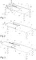
- FIG Figure 1 A first possible embodiment of the table 1 according to the invention together with a first possible embodiment of the table extension fitting 3 according to the invention is shown in FIG Figure 1 shown in a three-dimensional view obliquely from below.
- the table 1 can also have any other shape, for example a square shape.
- the table has four table legs 1.3, 1.4, 1.5 and 1.6.
- the table extension fitting 3 carries a pull-out plate 4. Both are located in Figure 1 in a parking position, which is also referred to as the stowed position. In this position, the table extension fitting 3 and the pull-out plate 4, which is also referred to as the table extension plate, are not visible from the usual viewing angles.
- the table extension fitting 3 and the pull-out plate 4 can be mounted below the table top 2 so far away from the end face 2.5 of the table top that they are not visible from the end face 2.5 of the table either.
- the pull-out plate 4 is attached to the table extension fitting 3 under the table 1 in such a way that its visible side 4.1, ie the beautiful side that is visible to the user, points downwards in the parking position.
- the table extension fitting 3 is preferably designed in such a way that the pull-out plate 4 is aligned parallel to the table top 2 in the parking position. In the parking position, the side face 4.4 of the pull-out panel 4 preferably runs parallel to the longitudinal side 2.4 of the table top 2.
- the table extension fitting 3 in the embodiment according to FIG Figure 1 a first linear guide 5 and a second linear guide 6.
- the one linear guide or the two linear guides 5 and 6 are preferably arranged under the table top 2 in such a way that the displacement path of the pull-out plate 4 runs parallel to the x-axis and thus also parallel to the longitudinal axis of the table 1.
- Any type of guide that enables linear, that is to say essentially rectilinear, movement can serve as the linear guide.
- the user can pull the table extension fitting 3 and the pull-out plate 4 even further in the direction of the arrow 30 under the table top 2 until the pull-out plate 4 is in the position shown in FIG Figure 3 so-called intermediate position shown has reached.
- the pull-out panel 4 is still aligned essentially parallel to the table top 2 and is now approximately halfway to the side next to the end face 2.5 of the table and thus also next to the table 1.
- One or more latching elements can be provided in order to hold the pull-out panel 4 in this tilted position.
- the pull-out panel 4 can be pulled out further or less from under the table top 2.
- the pull-out plate 4 is slightly wider than the dimension L (see Figure 6 ) can be pulled out from under the table top 2.
- the dimension L is the length of the pull-out panel 4.
- B is the width of the pull-out panel 4.
- the width B of the pull-out panel 4 is equal to the width of the table top 2, but this does not necessarily have to be the case.
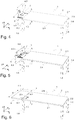
- Figure 4 shows the table 1 with the pull-out plate 4 in a three-dimensional view obliquely from above, the pull-out plate 4 being in the tilted position.
- the short side face 4.3 of the pull-out plate 4 is now at the bottom.
- the table extension fitting 3 has a tilting joint 7. In the present embodiment, this is located at the left end between the two linear guides 5 and 6.
- One or more latching elements can be provided to hold the pull-out panel 4 in this tilted position.
- the user now rotates the pull-out plate 4 by 90 ° in the direction of the arrow 32.
- the rotation takes place essentially in the yz plane.
- the table 1 with the pull-out plate 4 is shown obliquely from above, the pull-out plate 4 is now in the rotated position.
- the short side face 4.3 of the pull-out plate 4 is now no longer at the bottom, but on the left. So that the pull-out plate 4 can be rotated, the table extension fitting 3 has a rotary joint 8.
- the rotary joint 8 is preferably arranged in the middle of the tilt joint 7 and is connected to the pull-out plate 4.
- One or more latching elements can be provided in order to hold the pull-out plate 4 in this rotated position.
- FIG. 6 shows the table 1 with the pull-out plate 4 obliquely from above, the pull-out plate 4 being in the horizontal position.
- the side face 4.4 of the pull-out plate 4 is now located next to the end face 2.5 of the table top 2. In this position there is a gap F between the end face 2.5 of the table top 2 and the side face 4.4 of the pull-out plate 4.
- One or more locking elements can be provided around the Hold pull-out plate 4 in this horizontal position.
- the latching element or elements can also be magnets, for example.
- FIG. 7 shows the table 1 with the pull-out plate 4 from below, the pull-out plate 4 being in the position of use just described.
- FIG 8 a section of the table 1 with the pull-out plate 4 is shown in a three-dimensional view obliquely from above.
- the pull-out plate 4 is in the rotated position (see also Figure 5 ).
- the pull-out plate 4 is advantageously mounted on the rotary joint 8 in such a way that the center of gravity of the pull-out plate 4 is in the vicinity of the rotary joint 8. As a result, the effort required to tilt and rotate the pull-out shelf is minimal.
- the pull-out plate 4 can be connected to the rotary joint 8 by means of screws. However, other connections between the pull-out plate 4 and the rotary joint 8 are also possible.
- One or more stops can be provided on the side 4.2 of the pull-out plate 4, which is not visible in the position of use.
- a stop 14 and a stop 15 are mounted on the side 4.2 of the pull-out plate 4. With the help of the two stops 14 and 15 it is achieved that the pull-out plate 4 can be rotated back and forth between the two stops 14 and 15. Accidental rotation beyond the two stops 14 and 15 is thus safely and easily avoided.
- one or more compensation elements can be attached to the pull-out plate 4.
- the embodiment shown is a first compensating element on the non-visible side 4.2 of the pull-out plate 4 12 and a second compensation element 13 attached.
- the compensating elements 12 and 13 are preferably height-adjustable and serve to compensate for a possible difference in height between the table top 2 and the pull-out top 4, so that a shoulder between the table top 2 and the pull-out top 4 is avoided.
- the compensation elements 12 and 13 can also serve as a buffer if necessary.
- the compensation elements can be equipped with an elastic and / or sound-absorbing material. If the pull-out plate 4 is out of the in Figure 5 shown rotated position in the tilted position according to Figure 6 is brought, the compensating elements 12 and 13 acting as buffers ensure that the pull-out plate 4 does not hit the two linear guides 5 and 6 hard.
- the buffer or buffers can also be arranged on the linear guide or guides.
- the illustrated embodiment form a first bolt 10 and a second bolt 11 to prevent tilting. They are located on the non-visible side 4.2 and protrude beyond the side face 4.4 of the pull-out plate 4. As soon as the pull-out plate is pushed up to the front side 2.5 of the table top 2 and is therefore in the position of use, the two latches 10 and 11 engage under the table top 2 and thus prevent the pull-out plate 4 from accidentally tilting away.
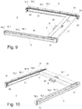
- a first possible embodiment of the table extension fitting 3 in the parking position is shown obliquely from above in a first or a second view.
- the table extension fitting 3 can be attached to a table top with the aid of a first angle 16 and a second angle 19.
- the table extension fitting 3 is preferably arranged centrally to the longitudinal axis of the table top.
- the table extension fitting 3 is arranged on the underside of the table top in such a way that the longitudinal axis of the table extension fitting 3 is congruent with the longitudinal axis of the table.
- the longitudinal axis of the table extension fitting 3 is generally congruent with the axis of rotation 80 of the rotary joint 8.
- the embodiment of the table extension fitting 3 according to the Figures 9 to 12 has two linear guides 5 and 6 arranged parallel to one another.
- the first linear guide 5 in turn comprises a first guide rail 17 and a second guide rail 18, which are movable relative to one another.
- the angle 16 is attached to the first guide rail 17 and has a number of holes 16.1 and a number of elongated holes 16.2.
- these are not absolutely necessary. For example, only holes or only elongated holes can be provided.
- the second linear guide 6 has a first guide rail 20 and a second guide rail 21, which are also movable relative to one another.
- the angle 19 is attached to the guide rail 20 and has a number of holes 19.1 and a number of elongated holes 19.2. However, these are not absolutely necessary.
- the holes 16.1 and 19.1 are also referred to as fixed bearings and the elongated holes 16.2 and 19.2 as floating bearings.
- the table extension fitting 3 can be screwed to a table top 1, which is made, for example, from pressboard.
- the table extension fitting 3 can be screwed to a table top 1, which is made of solid wood, for example.
- the floating bearings 16.2 and 19.2 ensure that the table top can work, that is, it can shrink and expand, without the fitting 3 twisting, warping or other undesirable effects occurring.
- a clamp can be provided on the guide rail 17 (not shown in the figures).
- the guide rail 18 is pulled out far enough, the end of the guide rail 18 snaps into the clamp and is thus held in this position. With a little pressure, the guide rail 18 can also be pushed out of the clamp again. The same applies analogously to the guide rail 21.
- the tilt joint 7 is rotatably mounted on the carriage 25.
- a clamp 22 can be provided at the end of the guide rail 21 (see Fig. 10 ). When the carriage 25 is pulled out far enough, the carriage 25 snaps into the bracket 22 and is thus held in this position. With a little pressure, the carriage 25 can also be pushed out of the clamp 22 again.
- Such a clamp can also be built into the guide rail 18.
- Another clamp 23 can be provided at the other end of the guide rail 21 (see FIG Fig. 11 ).
- the carriage 25 When the carriage 25 is pushed back into the parking position, the carriage 25 snaps into the bracket 23 and is thus held in this position. With a little force, the carriage 25 can also be pulled out of the clamp 23 again.
- Such a clamp can also be built into the guide rail 21.
- a pivot and tilt joint when the present invention refers to a pivot and tilt joint, this means a combination of a pivot joint and a tilt joint.
- a possible embodiment of such a swivel and tilt joint is, inter alia, in the Figures 9 to 12 shown.
- the turn-tilt joint can, however, also be designed differently.
- a ball joint is also conceivable for this.
- the tilt joint 7 is located in the embodiment according to Figures 9 to 12 between the two linear guides 5 and 6 and is rotatably connected to these.
- the tilting joint 7 is essentially formed by a tube, the ends 7.1 and 7.2 of which are rotatably mounted in corresponding bearing points 25.1 and 25.1 of the carriage 25.
- the axis about which the tilt joint 7 can rotate is referred to as the tilt axis 70.
- the rotary joint 8 is located in the embodiment according to Figures 9 to 12 in the middle of the tilt joint 8 and is rotatably connected to it.
- the axis about which the rotary joint 8 can rotate is referred to as the axis of rotation 80.
- the rotary joint 8 has a mounting plate 8.1 with a number of holes 8.2 via which the pull-out plate 4 can be connected to the mounting plate 8.1 and thus to the rotary joint 8.
- the axis of rotation 80 and the tilt axis 70 are perpendicular to one another.
- a strut 9 can be provided which, as shown in the figures, is arranged between the two linear guides 5 and 6.
- the carriage is formed by the strut 9 and the two parts 25.
- the strut 9 is rigidly connected to the two parts 25.
- the two bearings for the tilt joint 7 are located in parts 25.
- Figure 10 shows the first embodiment of the table extension fitting 3 in the extended position from the same viewing angle as in FIG Figure 9 .
- Figure 11 show the first embodiment of the table extension fitting in the extended position from the same angle as in FIG Figure 10 .
- the tilt joint 7 is shown rotated by 90 °. This position of the table extension fitting 3 corresponds to that in Figure 8 .
- the preceding description of the exemplary embodiments according to the present invention serves only for illustrative purposes and not for the purpose of restricting the invention.
- Various changes and modifications are possible within the scope of the invention without departing from the scope of the invention and its equivalents.
- the in Figure 8 The latch 10 and 11 shown can also be designed differently or can be replaced by a different anti-tip device.
- the side face 4.2 of the pull-out panel 4 and the end face 2.5 of the table top 2 can be shaped, for example, in such a way that they form a tilt protection when they are joined together.
- the anti-tipping device can also be integrated into the pivot and tilt joint 7, 8.
- the carriage 25 is not present.
- the two guide rails 18 and 21 have bearings in which the tilt joint 7 is rotatably mounted.
- the two guide rails 18 and 21 are not present.
- the car is 25 can be moved back and forth in the guide rails 17 and 20.
- bearings are provided in which the tilt joint 7 is rotatably mounted.
Landscapes
- Tables And Desks Characterized By Structural Shape (AREA)
Claims (14)
- Armature pour rallonge de table pour une table avec un plateau de table et un plateau de rallonge, comprenant- une rallonge (5, 6) qui est prévue pour être fixée sur la partie inférieure (2.2) du plateau de table (2), le plateau de rallonge (4) étant déplaçable avec la rallonge (5, 6) entre une position d'arrêt se trouvant sous le plateau de table (2) et une position intermédiaire se trouvant à côté du plateau de table (2),- une articulation pivotante-basculante (7, 8) qui est reliée à la rallonge (5, 6) et prévue pour être fixée sur le plateau de rallonge (4), le plateau de rallonge (4) étant pivotant et basculant avec l'articulation pivotante-basculante (7, 8) de façon à être déplaçable entre la position intermédiaire et une position d'utilisation,- sur laquelle l'articulation pivotante-basculante (7, 8) permet une rotation autour d'un axe de rotation (80) et un basculement autour d'un axe de basculement (70),- l'axe de rotation (80) et l'axe de basculement (70) étant orientés horizontalement dans le cas d'une utilisation conforme de l'armature pour rallonge de table (3),caractérisée en ce que- l'articulation pivotante-basculante (7, 8) est conçue de telle manière à ce que l'axe de rotation (80) et l'axe de basculement (70) soient sensiblement perpendiculaires l'un par rapport à l'autre.
- Armature pour rallonge de table selon la revendication 1,
sur laquelle la rallonge (5, 6) présente un guide linéaire (5; 6). - Armature pour rallonge de table selon la revendication 2, sur laquelle le guide linéaire (3; 4) est conçu comme extension complète ou comme super extension.
- Armature pour rallonge de table selon la revendication 2 ou 3,
sur laquelle la rallonge (5, 6) présente un autre guide linéaire (6; 5). - Armature pour rallonge de table selon la revendication 4,
sur laquelle la distance entre les deux guides linéaires (5, 6) est plus grande que la largeur (L) du plateau de rallonge (4). - Armature pour rallonge de table selon l'une des revendications 2 à 5,
sur laquelle le guide linéaire (5; 6) présente au moins un palier fixe (16.1; 19.1) et/ou au moins un palier libre (16.2; 19.2). - Armature pour rallonge de table selon l'une des revendications 4 à 6,
sur laquelle l'articulation pivotante-basculante (7, 8) est disposée entre les deux guides linéaires (5, 6) et est reliée en rotation à ces derniers. - Armature pour rallonge de table selon l'une des revendications 1 à 7,
sur laquelle l'articulation pivotante-basculante (7, 8) présente une articulation pivotante (8) et une articulation basculante (7),
l'articulation basculante (7) étant reliée en rotation au guide linéaire (5; 6), et
l'articulation pivotante (8) étant reliée en rotation à l'articulation basculante (7). - Armature pour rallonge de table selon la revendication 8,
sur laquelle l'articulation pivotante (8) présente une plaque de montage (8) pour la fixation de la plaque de rallonge (4). - Armature pour rallonge de table selon la revendication 8 ou 9,
sur laquelle l'articulation pivotante (8) est disposée au centre entre les deux guides linéaires (5, 6). - Armature pour rallonge de table selon l'une des revendications 1 à 10,
sur laquelle un dispositif d'encliquetage permettant de retenir l'articulation pivotante-basculante (7, 8) dans une position définie, est prévu sur la rallonge (5, 6). - Armature pour rallonge de table selon l'une des revendications 1 à 11,
sur laquelle une sécurité anti-basculement (10, 11) pour éviter un basculement accidentel de la plaque de rallonge (4) est prévue. - Table avec une armature pour rallonge de table selon l'une des revendications précédentes 1 à 12,
sur laquelle la plaque de rallonge (4) est fixée, avec la face visible (4.1) vers le bas, sur l'armature pour rallonge de table (3). - Table avec une armature pour rallonge de table selon l'une des revendications précédentes 1 à 12,
sur laquelle la rallonge (5, 6) est fixée sur le plateau de table (2) au milieu du plateau de table (2).
Priority Applications (1)
| Application Number | Priority Date | Filing Date | Title |
|---|---|---|---|
| EP14151484.4A EP2896320B1 (fr) | 2014-01-16 | 2014-01-16 | Ferrure de rallonge de table pour une table dotée d'un plateau de table et d'un plateau coulissant et table dotée d'une ferrure de rallonge de table |
Applications Claiming Priority (1)
| Application Number | Priority Date | Filing Date | Title |
|---|---|---|---|
| EP14151484.4A EP2896320B1 (fr) | 2014-01-16 | 2014-01-16 | Ferrure de rallonge de table pour une table dotée d'un plateau de table et d'un plateau coulissant et table dotée d'une ferrure de rallonge de table |
Publications (2)
| Publication Number | Publication Date |
|---|---|
| EP2896320A1 EP2896320A1 (fr) | 2015-07-22 |
| EP2896320B1 true EP2896320B1 (fr) | 2021-08-25 |
Family
ID=49920299
Family Applications (1)
| Application Number | Title | Priority Date | Filing Date |
|---|---|---|---|
| EP14151484.4A Active EP2896320B1 (fr) | 2014-01-16 | 2014-01-16 | Ferrure de rallonge de table pour une table dotée d'un plateau de table et d'un plateau coulissant et table dotée d'une ferrure de rallonge de table |
Country Status (1)
| Country | Link |
|---|---|
| EP (1) | EP2896320B1 (fr) |
Families Citing this family (3)
| Publication number | Priority date | Publication date | Assignee | Title |
|---|---|---|---|---|
| DE112018006985A5 (de) * | 2018-01-31 | 2020-10-08 | Oelschläger Metalltechnik GmbH | Elektrisch höhenverstellbarer tisch sowie verfahren zum steuern desselben |
| CN108652200A (zh) * | 2018-05-14 | 2018-10-16 | 郑州艾莫弗信息技术有限公司 | 一种计算机技术研发人员用多功能书桌 |
| CN113749405B (zh) * | 2021-08-31 | 2023-04-28 | 泰州市华晨曲木家具有限公司 | 一种带有桌面自延伸式机构的智能家居用餐桌 |
Family Cites Families (5)
| Publication number | Priority date | Publication date | Assignee | Title |
|---|---|---|---|---|
| DE10119176A1 (de) * | 2001-04-10 | 2002-10-17 | Georg Appeltshauser | Ausziehtisch |
| WO2007034514A1 (fr) * | 2005-09-19 | 2007-03-29 | Societa'vetraria Biancadese Sas | Table ayant au moins une extension capable d'etre deployee par des mouvements de rotation |
| DE202006004911U1 (de) | 2006-03-24 | 2006-06-14 | Wössner GmbH | Tisch |
| DE202010005991U1 (de) | 2010-04-23 | 2010-07-15 | Alfons Venjakob Gmbh & Co. Kg | Tisch |
| DE202010008880U1 (de) | 2010-10-22 | 2011-02-24 | Heinrich Rotterdam Gmbh U. Co. Kg | Tischverlängerung mit Hub-Dreh-Beschlag |
-
2014
- 2014-01-16 EP EP14151484.4A patent/EP2896320B1/fr active Active
Non-Patent Citations (1)
| Title |
|---|
| None * |
Also Published As
| Publication number | Publication date |
|---|---|
| EP2896320A1 (fr) | 2015-07-22 |
Similar Documents
| Publication | Publication Date | Title |
|---|---|---|
| EP2260229B1 (fr) | Support pour instruments, réglable en hauteur | |
| EP2424421B1 (fr) | Dispositif de réglage en hauteur d'un support guidé sur au moins une glissière d'extraction dans un appareil électroménager | |
| WO2008135270A1 (fr) | Ferrure pour armoire d'angle comprenant un plateau monobloc extractible | |
| EP3009038B1 (fr) | Table pliante amovible pour meuble | |
| EP2896320B1 (fr) | Ferrure de rallonge de table pour une table dotée d'un plateau de table et d'un plateau coulissant et table dotée d'une ferrure de rallonge de table | |
| EP3586674A1 (fr) | Unité de panneau de table pourvue d'insert abattant pour une table à rallonge | |
| DE3401170C2 (de) | Möbelstück mit einer versenkbaren Tischplatte | |
| DE2530603A1 (de) | An einer wand befestigbare arbeits- oder schreibplatte | |
| EP0804887B1 (fr) | Superstructure pour tables de travail | |
| EP0274569B1 (fr) | Bureau avec tablette supplémentaire | |
| DE202018105596U1 (de) | Umbaubares Stuhl/Tisch-Möbel | |
| EP2544568B1 (fr) | Meuble et ferrure pour un meuble | |
| DE19826463C2 (de) | Tisch mit verschwenkbarer Ergänzungsplatte | |
| EP1989953B1 (fr) | Armature pour une armoire angulaire dotée d'une étagère en une partie amovible | |
| DE202013105915U1 (de) | Ausziehtisch | |
| EP2215927B1 (fr) | Table | |
| EP1969963B1 (fr) | Dispositif de plateaux de table | |
| AT522096B1 (de) | Anordnung mit wenigstens einer Schubladenausziehführung und mit wenigstens einer Verriegelungsvorrichtung zum lösbaren Verriegeln eines ausziehbaren Möbelteiles | |
| DE19640210A1 (de) | Bett mit Ablageplatte | |
| DE102004052311B4 (de) | Möbel mit einem schrankähnlichen Korpus, in dem ein Schwenkbett klappbar gehalten ist | |
| DE102004054130B3 (de) | Tisch mit vergrößerbarer Tischplatte | |
| DE202011000472U1 (de) | Türbeschlag für Eckschränke | |
| EP1813170B1 (fr) | Meuble destiné à s'asseoir ou à s'allonger | |
| WO2002094060A1 (fr) | Meuble combine | |
| AT522008A1 (de) | Möbelbeschlag, Tisch mit einem Möbelbeschlag, sowie Verfahren zum Ausziehen eines Tisches |
Legal Events
| Date | Code | Title | Description |
|---|---|---|---|
| PUAI | Public reference made under article 153(3) epc to a published international application that has entered the european phase |
Free format text: ORIGINAL CODE: 0009012 |
|
| 17P | Request for examination filed |
Effective date: 20140116 |
|
| AK | Designated contracting states |
Kind code of ref document: A1 Designated state(s): AL AT BE BG CH CY CZ DE DK EE ES FI FR GB GR HR HU IE IS IT LI LT LU LV MC MK MT NL NO PL PT RO RS SE SI SK SM TR |
|
| AX | Request for extension of the european patent |
Extension state: BA ME |
|
| 17P | Request for examination filed |
Effective date: 20160122 |
|
| RBV | Designated contracting states (corrected) |
Designated state(s): AL AT BE BG CH CY CZ DE DK EE ES FI FR GB GR HR HU IE IS IT LI LT LU LV MC MK MT NL NO PL PT RO RS SE SI SK SM TR |
|
| STAA | Information on the status of an ep patent application or granted ep patent |
Free format text: STATUS: EXAMINATION IS IN PROGRESS |
|
| 17Q | First examination report despatched |
Effective date: 20200213 |
|
| GRAP | Despatch of communication of intention to grant a patent |
Free format text: ORIGINAL CODE: EPIDOSNIGR1 |
|
| STAA | Information on the status of an ep patent application or granted ep patent |
Free format text: STATUS: GRANT OF PATENT IS INTENDED |
|
| INTG | Intention to grant announced |
Effective date: 20210526 |
|
| GRAS | Grant fee paid |
Free format text: ORIGINAL CODE: EPIDOSNIGR3 |
|
| GRAA | (expected) grant |
Free format text: ORIGINAL CODE: 0009210 |
|
| STAA | Information on the status of an ep patent application or granted ep patent |
Free format text: STATUS: THE PATENT HAS BEEN GRANTED |
|
| AK | Designated contracting states |
Kind code of ref document: B1 Designated state(s): AL AT BE BG CH CY CZ DE DK EE ES FI FR GB GR HR HU IE IS IT LI LT LU LV MC MK MT NL NO PL PT RO RS SE SI SK SM TR |
|
| REG | Reference to a national code |
Ref country code: GB Ref legal event code: FG4D Free format text: NOT ENGLISH |
|
| REG | Reference to a national code |
Ref country code: CH Ref legal event code: EP |
|
| REG | Reference to a national code |
Ref country code: DE Ref legal event code: R096 Ref document number: 502014015823 Country of ref document: DE |
|
| REG | Reference to a national code |
Ref country code: IE Ref legal event code: FG4D Free format text: LANGUAGE OF EP DOCUMENT: GERMAN Ref country code: AT Ref legal event code: REF Ref document number: 1422898 Country of ref document: AT Kind code of ref document: T Effective date: 20210915 |
|
| REG | Reference to a national code |
Ref country code: LT Ref legal event code: MG9D |
|
| REG | Reference to a national code |
Ref country code: NL Ref legal event code: MP Effective date: 20210825 |
|
| PG25 | Lapsed in a contracting state [announced via postgrant information from national office to epo] |
Ref country code: PT Free format text: LAPSE BECAUSE OF FAILURE TO SUBMIT A TRANSLATION OF THE DESCRIPTION OR TO PAY THE FEE WITHIN THE PRESCRIBED TIME-LIMIT Effective date: 20211227 Ref country code: NO Free format text: LAPSE BECAUSE OF FAILURE TO SUBMIT A TRANSLATION OF THE DESCRIPTION OR TO PAY THE FEE WITHIN THE PRESCRIBED TIME-LIMIT Effective date: 20211125 Ref country code: ES Free format text: LAPSE BECAUSE OF FAILURE TO SUBMIT A TRANSLATION OF THE DESCRIPTION OR TO PAY THE FEE WITHIN THE PRESCRIBED TIME-LIMIT Effective date: 20210825 Ref country code: FI Free format text: LAPSE BECAUSE OF FAILURE TO SUBMIT A TRANSLATION OF THE DESCRIPTION OR TO PAY THE FEE WITHIN THE PRESCRIBED TIME-LIMIT Effective date: 20210825 Ref country code: BG Free format text: LAPSE BECAUSE OF FAILURE TO SUBMIT A TRANSLATION OF THE DESCRIPTION OR TO PAY THE FEE WITHIN THE PRESCRIBED TIME-LIMIT Effective date: 20211125 Ref country code: LT Free format text: LAPSE BECAUSE OF FAILURE TO SUBMIT A TRANSLATION OF THE DESCRIPTION OR TO PAY THE FEE WITHIN THE PRESCRIBED TIME-LIMIT Effective date: 20210825 Ref country code: SE Free format text: LAPSE BECAUSE OF FAILURE TO SUBMIT A TRANSLATION OF THE DESCRIPTION OR TO PAY THE FEE WITHIN THE PRESCRIBED TIME-LIMIT Effective date: 20210825 Ref country code: RS Free format text: LAPSE BECAUSE OF FAILURE TO SUBMIT A TRANSLATION OF THE DESCRIPTION OR TO PAY THE FEE WITHIN THE PRESCRIBED TIME-LIMIT Effective date: 20210825 Ref country code: HR Free format text: LAPSE BECAUSE OF FAILURE TO SUBMIT A TRANSLATION OF THE DESCRIPTION OR TO PAY THE FEE WITHIN THE PRESCRIBED TIME-LIMIT Effective date: 20210825 |
|
| PG25 | Lapsed in a contracting state [announced via postgrant information from national office to epo] |
Ref country code: PL Free format text: LAPSE BECAUSE OF FAILURE TO SUBMIT A TRANSLATION OF THE DESCRIPTION OR TO PAY THE FEE WITHIN THE PRESCRIBED TIME-LIMIT Effective date: 20210825 Ref country code: LV Free format text: LAPSE BECAUSE OF FAILURE TO SUBMIT A TRANSLATION OF THE DESCRIPTION OR TO PAY THE FEE WITHIN THE PRESCRIBED TIME-LIMIT Effective date: 20210825 Ref country code: GR Free format text: LAPSE BECAUSE OF FAILURE TO SUBMIT A TRANSLATION OF THE DESCRIPTION OR TO PAY THE FEE WITHIN THE PRESCRIBED TIME-LIMIT Effective date: 20211126 |
|
| PG25 | Lapsed in a contracting state [announced via postgrant information from national office to epo] |
Ref country code: NL Free format text: LAPSE BECAUSE OF FAILURE TO SUBMIT A TRANSLATION OF THE DESCRIPTION OR TO PAY THE FEE WITHIN THE PRESCRIBED TIME-LIMIT Effective date: 20210825 |
|
| PG25 | Lapsed in a contracting state [announced via postgrant information from national office to epo] |
Ref country code: DK Free format text: LAPSE BECAUSE OF FAILURE TO SUBMIT A TRANSLATION OF THE DESCRIPTION OR TO PAY THE FEE WITHIN THE PRESCRIBED TIME-LIMIT Effective date: 20210825 |
|
| REG | Reference to a national code |
Ref country code: DE Ref legal event code: R097 Ref document number: 502014015823 Country of ref document: DE |
|
| PG25 | Lapsed in a contracting state [announced via postgrant information from national office to epo] |
Ref country code: SM Free format text: LAPSE BECAUSE OF FAILURE TO SUBMIT A TRANSLATION OF THE DESCRIPTION OR TO PAY THE FEE WITHIN THE PRESCRIBED TIME-LIMIT Effective date: 20210825 Ref country code: SK Free format text: LAPSE BECAUSE OF FAILURE TO SUBMIT A TRANSLATION OF THE DESCRIPTION OR TO PAY THE FEE WITHIN THE PRESCRIBED TIME-LIMIT Effective date: 20210825 Ref country code: RO Free format text: LAPSE BECAUSE OF FAILURE TO SUBMIT A TRANSLATION OF THE DESCRIPTION OR TO PAY THE FEE WITHIN THE PRESCRIBED TIME-LIMIT Effective date: 20210825 Ref country code: EE Free format text: LAPSE BECAUSE OF FAILURE TO SUBMIT A TRANSLATION OF THE DESCRIPTION OR TO PAY THE FEE WITHIN THE PRESCRIBED TIME-LIMIT Effective date: 20210825 Ref country code: CZ Free format text: LAPSE BECAUSE OF FAILURE TO SUBMIT A TRANSLATION OF THE DESCRIPTION OR TO PAY THE FEE WITHIN THE PRESCRIBED TIME-LIMIT Effective date: 20210825 Ref country code: AL Free format text: LAPSE BECAUSE OF FAILURE TO SUBMIT A TRANSLATION OF THE DESCRIPTION OR TO PAY THE FEE WITHIN THE PRESCRIBED TIME-LIMIT Effective date: 20210825 |
|
| PLBE | No opposition filed within time limit |
Free format text: ORIGINAL CODE: 0009261 |
|
| STAA | Information on the status of an ep patent application or granted ep patent |
Free format text: STATUS: NO OPPOSITION FILED WITHIN TIME LIMIT |
|
| PG25 | Lapsed in a contracting state [announced via postgrant information from national office to epo] |
Ref country code: IT Free format text: LAPSE BECAUSE OF FAILURE TO SUBMIT A TRANSLATION OF THE DESCRIPTION OR TO PAY THE FEE WITHIN THE PRESCRIBED TIME-LIMIT Effective date: 20210825 |
|
| 26N | No opposition filed |
Effective date: 20220527 |
|
| PG25 | Lapsed in a contracting state [announced via postgrant information from national office to epo] |
Ref country code: SI Free format text: LAPSE BECAUSE OF FAILURE TO SUBMIT A TRANSLATION OF THE DESCRIPTION OR TO PAY THE FEE WITHIN THE PRESCRIBED TIME-LIMIT Effective date: 20210825 Ref country code: MC Free format text: LAPSE BECAUSE OF FAILURE TO SUBMIT A TRANSLATION OF THE DESCRIPTION OR TO PAY THE FEE WITHIN THE PRESCRIBED TIME-LIMIT Effective date: 20210825 |
|
| GBPC | Gb: european patent ceased through non-payment of renewal fee |
Effective date: 20220116 |
|
| REG | Reference to a national code |
Ref country code: BE Ref legal event code: MM Effective date: 20220131 |
|
| PG25 | Lapsed in a contracting state [announced via postgrant information from national office to epo] |
Ref country code: LU Free format text: LAPSE BECAUSE OF NON-PAYMENT OF DUE FEES Effective date: 20220116 Ref country code: GB Free format text: LAPSE BECAUSE OF NON-PAYMENT OF DUE FEES Effective date: 20220116 |
|
| PG25 | Lapsed in a contracting state [announced via postgrant information from national office to epo] |
Ref country code: FR Free format text: LAPSE BECAUSE OF NON-PAYMENT OF DUE FEES Effective date: 20220131 Ref country code: BE Free format text: LAPSE BECAUSE OF NON-PAYMENT OF DUE FEES Effective date: 20220131 |
|
| PG25 | Lapsed in a contracting state [announced via postgrant information from national office to epo] |
Ref country code: IE Free format text: LAPSE BECAUSE OF NON-PAYMENT OF DUE FEES Effective date: 20220116 |
|
| REG | Reference to a national code |
Ref country code: DE Ref legal event code: R082 Ref document number: 502014015823 Country of ref document: DE Representative=s name: NUECKEL, THOMAS, DIPL.-ING. (UNIV.), CH |
|
| PG25 | Lapsed in a contracting state [announced via postgrant information from national office to epo] |
Ref country code: HU Free format text: LAPSE BECAUSE OF FAILURE TO SUBMIT A TRANSLATION OF THE DESCRIPTION OR TO PAY THE FEE WITHIN THE PRESCRIBED TIME-LIMIT; INVALID AB INITIO Effective date: 20140116 |
|
| PG25 | Lapsed in a contracting state [announced via postgrant information from national office to epo] |
Ref country code: MK Free format text: LAPSE BECAUSE OF FAILURE TO SUBMIT A TRANSLATION OF THE DESCRIPTION OR TO PAY THE FEE WITHIN THE PRESCRIBED TIME-LIMIT Effective date: 20210825 Ref country code: CY Free format text: LAPSE BECAUSE OF FAILURE TO SUBMIT A TRANSLATION OF THE DESCRIPTION OR TO PAY THE FEE WITHIN THE PRESCRIBED TIME-LIMIT Effective date: 20210825 |
|
| PG25 | Lapsed in a contracting state [announced via postgrant information from national office to epo] |
Ref country code: MT Free format text: LAPSE BECAUSE OF FAILURE TO SUBMIT A TRANSLATION OF THE DESCRIPTION OR TO PAY THE FEE WITHIN THE PRESCRIBED TIME-LIMIT Effective date: 20210825 |
|
| PG25 | Lapsed in a contracting state [announced via postgrant information from national office to epo] |
Ref country code: TR Free format text: LAPSE BECAUSE OF FAILURE TO SUBMIT A TRANSLATION OF THE DESCRIPTION OR TO PAY THE FEE WITHIN THE PRESCRIBED TIME-LIMIT Effective date: 20210825 |
|
| REG | Reference to a national code |
Ref country code: CH Ref legal event code: U11 Free format text: ST27 STATUS EVENT CODE: U-0-0-U10-U11 (AS PROVIDED BY THE NATIONAL OFFICE) Effective date: 20260201 |
|
| PGFP | Annual fee paid to national office [announced via postgrant information from national office to epo] |
Ref country code: DE Payment date: 20260131 Year of fee payment: 13 |
|
| PGFP | Annual fee paid to national office [announced via postgrant information from national office to epo] |
Ref country code: AT Payment date: 20260102 Year of fee payment: 13 |
|
| PGFP | Annual fee paid to national office [announced via postgrant information from national office to epo] |
Ref country code: CH Payment date: 20260201 Year of fee payment: 13 |