EP2897457B1 - Fahrzeug ausgerüstet mit einer schiebervorrichtung zum schieben von futter am boden - Google Patents
Fahrzeug ausgerüstet mit einer schiebervorrichtung zum schieben von futter am boden Download PDFInfo
- Publication number
- EP2897457B1 EP2897457B1 EP13762493.8A EP13762493A EP2897457B1 EP 2897457 B1 EP2897457 B1 EP 2897457B1 EP 13762493 A EP13762493 A EP 13762493A EP 2897457 B1 EP2897457 B1 EP 2897457B1
- Authority
- EP
- European Patent Office
- Prior art keywords
- vehicle
- pusher member
- vehicle according
- pusher
- ground
- Prior art date
- Legal status (The legal status is an assumption and is not a legal conclusion. Google has not performed a legal analysis and makes no representation as to the accuracy of the status listed.)
- Active
Links
Images


Classifications
-
- A—HUMAN NECESSITIES
- A01—AGRICULTURE; FORESTRY; ANIMAL HUSBANDRY; HUNTING; TRAPPING; FISHING
- A01K—ANIMAL HUSBANDRY; AVICULTURE; APICULTURE; PISCICULTURE; FISHING; REARING OR BREEDING ANIMALS, NOT OTHERWISE PROVIDED FOR; NEW BREEDS OF ANIMALS
- A01K5/00—Feeding devices for stock or game ; Feeding wagons; Feeding stacks
- A01K5/02—Automatic devices
-
- A—HUMAN NECESSITIES
- A01—AGRICULTURE; FORESTRY; ANIMAL HUSBANDRY; HUNTING; TRAPPING; FISHING
- A01K—ANIMAL HUSBANDRY; AVICULTURE; APICULTURE; PISCICULTURE; FISHING; REARING OR BREEDING ANIMALS, NOT OTHERWISE PROVIDED FOR; NEW BREEDS OF ANIMALS
- A01K1/00—Housing animals; Equipment therefor
- A01K1/10—Feed racks
- A01K1/105—Movable feed barriers
-
- A—HUMAN NECESSITIES
- A01—AGRICULTURE; FORESTRY; ANIMAL HUSBANDRY; HUNTING; TRAPPING; FISHING
- A01K—ANIMAL HUSBANDRY; AVICULTURE; APICULTURE; PISCICULTURE; FISHING; REARING OR BREEDING ANIMALS, NOT OTHERWISE PROVIDED FOR; NEW BREEDS OF ANIMALS
- A01K5/00—Feeding devices for stock or game ; Feeding wagons; Feeding stacks
- A01K5/02—Automatic devices
- A01K5/0266—Automatic devices with stable trolleys, e.g. suspended
Definitions
- the present invention relates to the field of livestock farming, and more particularly livestock feeding.
- a barn usually includes a living area separated from a feeding corridor by a feeding barrier allowing livestock in the air of life to pass the head to feed in the feeding corridor.
- the feed barrier is for example a cornadis.
- Food (fodder, granules ...) are deposited along the feed barrier.
- the composition of feeds and their quantity are determined for proper feeding of livestock. By eating, animals push food away from the feeding fence. It is desirable to push foods back to the feeding barrier to allow animals to feed at the appropriate dose.
- EP 1 779 722 A1 discloses vehicles for pushing food on the ground toward a feed fence.
- a vehicle includes a V-shaped scraper blade pointing forwards to repel food on the sides of the vehicle due to movement of the vehicle.
- Another vehicle comprises a rectilinear scraper blade rotatable about a vertical axis to repel food on the side of the vehicle by reciprocating movement of the scraper blade combined with incremental movement of the vehicle.
- Still another vehicle comprises a rectilinear scraping blade extending parallel to the longitudinal direction of the vehicle and movable in translation in a transverse direction of the vehicle to repel the food by an alternating translational movement combined with an incremental movement of the vehicle.
- EP 2,007,191 A1 discloses an unmanned autonomous vehicle for pushing food on the ground, comprising a carriage provided with a rotating circular element surrounding the carriage and rotatably mounted about an axis close to the vertical, for pushing the food on the ground against a barrier power.
- NL 9 400 771 A1 disclose vehicles to push food on the ground.
- DE 101 18 026 C1 discloses a tractor with a pusher device having a pusher member adjustable in particular by sliding in a transverse direction of the tractor.
- One of the aims of the invention is to provide a pusher device for pushing food on the ground in front of a vehicle, which is effective and easy to implement.
- the invention proposes a vehicle, according to claim 1.
- the vehicle comprises one or more of the optional features of claims 2 to 15.
- the invention also relates to a feed installation of livestock according to claim 16.
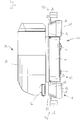
- the vehicle 2 represented on the Figures 1 to 6 is an automatic vehicle. He is autonomous and unmanned. It is designed to move automatically according to a specific program, identifying itself in its environment, possibly with the help of a guide or beacons.
- the vehicle 2 is configured to move in a barn feed corridor, along a feed fence 3 separating the feed chute from a cattle life area, by pushing food to ground against the feed fence 3.
- the fence allows cattle to move their head to eat food placed on the ground along the feed fence.
- the vehicle 2 is provided to move in a longitudinal direction L corresponding to the direction of rectilinear movement of the vehicle in forward or reverse.
- the vehicle 2 comprises a carriage 4 provided with wheels 6 for taxiing ( Figure 3 ).
- the carriage 4 comprises at least one motorized drive wheel for controlling the movement of the vehicle 2 forwards or backwards and at least one steering wheel for controlling the direction of the vehicle 2.
- the vehicle 2 comprises an automatic guiding device 8 for controlling the movements of the vehicle automatically.
- the guiding device 8 comprises for example an electromagnetic sensor cooperating with a continuous wire buried in the ground or with magnetic terminals buried in the ground at a distance from each other.
- the guiding device comprises an optical sensor cooperating with a line drawn on the ground, marks drawn on the ground or elevated marks distributed in the barn.
- the device comprises a laser detector and reflective terminals distributed in the barn.
- the guiding device comprises a vision device comprising at least one camera, preferably two cameras for stereoscopic vision, and an image analysis device capable of recognizing the environment of the vehicle after learning.
- the guiding device 8 controls the driving of the or each driving wheel and the orientation of the or each control wheel to control the movements of the vehicle 2.
- the vehicle 2 comprises a pusher device 12 for pushing food on the ground in front of the vehicle 2.
- the pusher device 12 comprises a pushing member 14 - or scraper - configured to be moved along the ground and push food on the ground laterally on the side of the vehicle 2 in a transverse direction T, due to the displacement of the pusher device 12 according to the longitudinal direction L, the transverse direction T being perpendicular to the longitudinal direction L.
- the pusher member 14 is here formed to push food laterally on both sides of the pusher member 14.
- the pusher member 14 forms a scraper bow. It is shaped "V" pointing in the longitudinal direction, towards the outside of the vehicle 2, here forward.
- the pusher member 14 has two lateral segments 16 ( Figures 6 and 4 ), each oriented to push food laterally onto a respective side of the vehicle 2. Each lateral segment is inclined with respect to the longitudinal direction L and the transverse direction T is oriented towards the front and towards a respective lateral side of the vehicle. vehicle.
- the two lateral segments 16 are connected by a convex transverse curvilinear intermediate segment 18 extending transversely.
- the pusher member 14 is provided on its lower edge with a wear strip 20 ( Figures 1 to 4 ) by which the pusher member 14 rubs on the ground. Wear strip 20 is replaced when worn.
- the pusher member 14 is movable in translation in the transverse direction T, between a retracted position ( Figures 1 and 3 ), in which the pusher member 14 fits in view along the longitudinal direction L in the width of the carriage 4, without projecting laterally with respect to the carriage 4, and an extended position ( Figure 2 and 4 ), wherein the pusher member 14 is offset transversely with respect to the retracted position, the pusher member 14 protruding transversely of the carriage 4, on a lateral side thereof.
- the pusher member 14 is preferably displaceable transversely in both directions, to a deployed position on the right, projecting on the right of the carriage 4 and towards a deployed position on the left, projecting on the left of the carriage 4.
- the pusher device 12 has an inactive configuration ( Figure 1 and 3 ) in which the pusher member 14 is raised away from the ground and an active configuration ( Figures 2 and 4 ) in which the pusher member 14 is lowered to push food on the ground.
- the pusher member 14 is in the retracted position, as illustrated in FIGS. Figures 1 and 3 , so as not to project laterally from the carriage 4.
- the pusher device 12 comprises a support 22 carrying the pusher member 14.
- the pusher member 14 is mounted on the support 22 being movable in translation in the transverse direction T relative to the support 22. This allows the displacement of the organ pusher 14 between the retracted position and the deployed position.
- the pusher device 12 comprises a deployment actuator for controlling the displacement of the pusher member 14 in the transverse direction T between the retracted position and the deployed position.
- the deployment actuator is disposed between the pusher member 14 and the support 22.
- the support 22 is mounted on the carriage 4 by being movable in translation in the vertical direction Z relative to the carriage 4 to lower the pusher member 14 in the active configuration of the pusher device 12 or raise the pusher member 14 in the inactive configuration of the device pusher 12.
- the pusher device 12 comprises a lifting actuator (not shown) for controlling the vertical displacement of the support 22 between the inactive configuration and the active configuration.
- the lifting actuator is arranged between the support 22 and the carriage 4.
- the lifting actuator is for example a pneumatic, hydraulic or electric actuator.
- the pusher device 12 comprises a front detection device 28 for detecting obstacles in front of the vehicle 2, in particular in front of the vehicle. pusher device 12.
- the detection device 28 is configured to automatically control the stopping of the vehicle 2 when an obstacle is detected on the trajectory of the vehicle 2.
- the detection device 28 here comprises a probe 30 extending cantilevered in front of the pusher member 14.
- the probe 30 extends transversely, substantially over the entire width of the vehicle 2.
- the probe 30 is carried by at least one arm, here two arms 32. Each arm 32 extends in the longitudinal direction L. Each arm 32 is telescopic to allow the probe 30 to move back when it hits an obstacle.
- the detection device 28 detects any contact of the probe 30 with an obstacle and immediately commands the stopping of the vehicle 2.
- the pusher member 14 does not project laterally with respect to the probe 30.
- the pusher member 14 projects laterally with respect to the probe 30.
- the detection device 28 is here a contact detection device.
- the detection device is a remote detection device, without contact.
- a detection device is for example an optical camera and image analysis device, a laser scanner device, an ultrasonic scanner device or any other type of contactless obstacle detection device.
- the detection device 28 has a low configuration ( Figure 1 and 3 ) in which the detection device 28 detects obstacles from a first height H1 , and a high configuration ( Figure 2 and 4 ) in which the detection device 28 detects obstacles from a second height H2 greater than the first height H1 .
- the low configuration allows detection with a higher security level, allowing obstacle detection from the first H1 height, and the high configuration allows detection with a lower security level, allowing detection of obstacle only from the second height H2 .
- the second height H2 is chosen to be greater than the height of food on the ground repulsed by livestock away from the feed barrier, and thus avoid an unnecessary stopping of the vehicle 2 when it pushes food on floor.
- the detection device 28 is placed in the low configuration when the pusher device 12 is in an inactive configuration, to ensure a level of security high, and the detection device 28 is placed in the high configuration when the pusher device 12 is in active configuration.
- the probe 30 is vertically movable between a low position ( Figure 3 ) corresponding to the low configuration and a high position ( Figure 4 ) corresponding to the high configuration.
- the first height H1 corresponds to the height of the lower edge of the probe 30 in the low position and the second height H2 corresponds to the height of the lower edge of the probe 30 in the high position.
- the detection device 28 is for example mounted on the support 22.
- the detection device 28 is mounted vertically movable on the support 22 with a sufficient amplitude to raise the probe 30 in the up position by compensating the downward movement of the support 22 for lowering the pusher member 14 near or in contact with the ground.
- the detection device 28 comprises an adjustment actuator (not shown) for lowering the probe 30 or raising the probe 30.
- the adjusting actuator is disposed between the support 22 and the arms 32.
- the adjustment actuator is for example a pneumatic, hydraulic or electric actuator.
- the pusher device 12 incorporating the detection device 28 forms a pusher module adapted to be mounted on an existing vehicle.
- the detection device 28 is disposed in the low configuration and the pusher member 14 is raised.
- the detection device 28 is disposed in the high configuration and the pusher member is lowered.
- the guiding device 8 controls the vehicle 2 to move the vehicle 2 along the feed barrier 3, preferably at a constant predetermined stopping distance from the feed barrier.
- the pusher member 14 pushes food lying in the path of the vehicle 2 towards the supply barrier 3.
- the vehicle 2 makes a first passage at the predetermined passage distance D with respect to the feed barrier, the pusher member 14 being lowered and in the retracted position.
- the vehicle 2 then performs a second pass, always at the same distance D , but the pusher member 14 is lowered in the deployed position.
- the pusher member 14 is offset laterally relative to the carriage 4 towards the supply barrier 3.
- the carriage 4 thus remains at the passage distance D of the feed barrier 3, while allowing the food to be brought closer to the feed barrier 3 at a distance appropriate for their consumption by the cattle.
- the guiding device 8 is configured such that the vehicle 2 moves at a first speed when the detection device 28 is in the low configuration, and at a second speed when the detection device 28 is in the configuration. high, the second speed being lower than the first speed.
- the vehicle 2 is provided with a pusher device 12 before and a rear pusher device 12, for example if the vehicle is configured to operate in forward and reverse, which allows for example to go back and forth without turning around.
- the vehicle 2 is advantageously provided with a dispensing assembly 34 for dispensing food along the feed barrier 3.
- the vehicle 2 thus forms an automatic food distribution vehicle.
- the dispensing assembly 34 comprises a container 36, a disentangler 38 for disentangling food received in the container 36, a conveyor 40 for pushing food received in the container 36 to the unraveler 38, and a dispenser 42 for dispensing food on the side of the vehicle 2.
- the conveyor 36 is for example a chain or belt conveyor.
- the unraveler 38 comprises at least one rotor 44, here two parallel rotors 44.
- the rotors 44 are oriented horizontally and rotatable about their respective axes. The rotation of the rotors 44 makes it possible to disentangle food pushed by the conveyor 36 towards the unraveler 38.
- the food comes for example from a silage and is initially compacted when poured into the container 36.
- the dispenser 42 is a belt dispenser opening laterally on the side of the vehicle 2 for depositing the food along a feed barrier 3 along which the vehicle 2 moves, for example between the vehicle 2 and the barrier 2. feeding 3.
- Maintaining the same passage distance D at the first passage and the second passage allows the dispenser 42 to deposit food appropriately along the feed barrier 3 during the two passages.
- Maintaining the same distance D passage at the first passage and the second passage keeps a sufficient distance from the cattle to avoid injuring animals.
- the transverse displacement of the pusher member 14 adjusts its transverse position to repel the food appropriately while maintaining the passage distance D for the vehicle 2.
- the vehicle 2 distributes food. Food is deposited along the feed fence by the distributor.
- the vehicle 2 preferably moves autonomously to collect food at automated feed loading stations and then to dispense food along the feed barriers.
- WO 2010/094902 discloses an automated animal feed installation comprising such unmanned autonomous vehicle and stations for preparing food to be dispensed by the vehicle.
- the vehicle 2 comprises a lateral detection device 50, comprising for example lateral sensors 52 extending along the lower edge of a lateral fairing 54 of the vehicle, for detecting obstacles coming into contact with the vehicle on the side.
- a lateral detection device 50 comprising for example lateral sensors 52 extending along the lower edge of a lateral fairing 54 of the vehicle, for detecting obstacles coming into contact with the vehicle on the side.
- the pusher member 14 In the deployed position, the pusher member 14 extends laterally beyond the lateral feelers 52.
- the pusher member 14 laterally offset protects the feelers 52 that are not activated by the pushed food.
- the vehicle 2 is independently provided with two pushing devices 12, a lateral detection device 50 or a dispensing assembly for dispensing food.
- the vehicle is mobile along a railroad provided on the ground.
- the vehicle is suspended from a rail along which it moves.
- the vehicle is preferably autonomous and unmanned. The vehicle moves automatically along the track or rail to push food to the ground and, where appropriate, to collect food at automated feed loading stations.
- the scraping device for repelling food is mounted on a crewed vehicle, the vehicle having a cockpit for an operator.
- the vehicle includes a manually operated steering control device or is guided along a railroad laid on the ground or suspended on a rail.
- the detection device is optional.
- the invention relates to a pusher device for pushing food on the ground, intended to equip a vehicle, the pusher device comprising a support and a pusher member carried by the support, the pusher member being adapted to push food on the floor and a detection device for detecting an obstacle present in front of the pusher device.
- the pusher device is configured to lower the pusher member close to the ground or raise the pusher member away from the ground
- the detection device has a low configuration to detect obstacles in front of the pusher device from a first height relative to the ground when the pusher member is raised and a high configuration for detecting obstacles in front of the pusher device from a second height greater than the first height when the pusher member is raised.
Landscapes
- Life Sciences & Earth Sciences (AREA)
- Environmental Sciences (AREA)
- Animal Husbandry (AREA)
- Biodiversity & Conservation Biology (AREA)
- Birds (AREA)
- Zoology (AREA)
- Feeding And Watering For Cattle Raising And Animal Husbandry (AREA)
- Guiding Agricultural Machines (AREA)
- Catching Or Destruction (AREA)
- Housing For Livestock And Birds (AREA)
Claims (16)
- Fahrzeug, umfassend einen Wagen (4) und eine Schubvorrichtung (12) zum Schieben von Nahrungsmitteln auf dem Boden, wobei die Schubvorrichtung (12) einen Träger (22) und ein Schubelement (14), das von dem Träger getragen wird, umfasst, wobei das Schubelement (14) dazu gedacht ist, Nahrungsmittel auf dem Boden auf der Seite des Fahrzeugs in einer Querrichtung (T) des Fahrzeugs durch die Fahrt des Fahrzeugs in einer Längsrichtung (L) des Fahrzeugs, die zur Querrichtung (T) rechtwinklig ist, zu schieben, dadurch gekennzeichnet, dass das Schubelement (14) im Verhältnis zum Träger (22) translationsmäßig in der Querrichtung (T) zwischen einer eingezogenen Position, in der sich das Schubelement zwischen den Seitenrändern des Wagens (4) befindet, und mindestens einer ausgefahrenen Position, in der das Schubelement (14) im Verhältnis zum Wagen (4) seitlich vorsteht, beweglich ist.
- Fahrzeug nach Anspruch 1, wobei die Schubvorrichtung (12) ein Ausfahrstellglied umfasst, um die Verschiebung des Schubelements (14) in der Querrichtung (T) zwischen der eingezogenen Position und der ausgefahrenen Position zu steuern.
- Fahrzeug nach Anspruch 1 oder 2, wobei das Schubelement (14) in der Querrichtung (T) zwischen einer eingezogenen Position und zwei ausgefahrenen Positionen, die sich auf beiden Seiten der eingezogenen Position befinden, beweglich ist.
- Fahrzeug nach einem der vorhergehenden Ansprüche, wobei das Schubelement (14) derart beweglich ist, dass es das Schubelement (14) dem Boden nähert oder davon entfernt, wenn die Schubvorrichtung an einem Fahrzeug montiert ist.
- Fahrzeug nach einem der vorhergehenden Ansprüche, wobei das Schubelement (14) in einer senkrechten Richtung (Z), die zu der Längsrichtung (L) und der Querrichtung (T) rechtwinklig ist, beweglich ist.
- Fahrzeug nach einem der vorhergehenden Ansprüche, wobei der Träger (22) in einer senkrechten Richtung (Z), die zu der Längsrichtung (L) und der Querrichtung (T) rechtwinklig ist, beweglich ist.
- Fahrzeug nach einem der vorhergehenden Ansprüche, umfassend eine Erkennungsvorrichtung (28) zum Erkennen eines Hindernisses, das sich vor der Schubvorrichtung (12) befindet.
- Fahrzeug nach Anspruch 7, wobei die Erkennungsvorrichtung (28) eine untere Konfiguration, um Hindernisse vor der Schubvorrichtung (12) von einer ersten Höhe (H1) im Verhältnis zum Boden aus zu erkennen, und eine obere Konfiguration, um Hindernisse vor der Schubvorrichtung (12) von einer zweiten Höhe (H2) aus, die höher als die erste Höhe (H1) ist, zu erkennen, umfasst.
- Fahrzeug nach Anspruch 7 oder 8, wobei die Erkennungsvorrichtung eine Erkennung mit oder ohne Kontakt aufweist.
- Fahrzeug nach einem der Ansprüche 7 bis 9, wobei die Erkennungsvorrichtung (28) einen Taster (30) umfasst, um ein Hindernis zu erkennen, das den Taster (30) berührt, wobei sich der Taster (30) in der Querrichtung (T) in einem Abstand von dem Schubelement (14) in der Längsrichtung (L) erstreckt.
- Fahrzeug nach Anspruch 10, wobei sich das Schubelement (14) in Längsrichtung (L) gesehen in der eingezogenen Position mit dem Taster (30) fluchtend befindet, und das Schubelement in der ausgefahrenen Position im Verhältnis zu dem Taster (30) quer vorsteht.
- Fahrzeug nach einem der vorhergehenden Ansprüche, autonom und unbemannt.
- Fahrzeug nach einem der vorhergehenden Ansprüche, umfassend eine automatische Führungsvorrichtung.
- Fahrzeug nach einem der vorhergehenden Ansprüche, wobei der Wagen (4) mit Bodenlaufrädern versehen ist, wozu mindestens ein motorisiertes Antriebsrad und mindestens ein Leitrad gehören.
- Fahrzeug nach einem der Ansprüche 1 bis 12, das entlang einer Rollbahn, die auf dem Boden bereitgestellt wird, oder an einer Schiene hängend, an der es sich entlang bewegt, beweglich ist.
- Nutztierernährungsanlage, umfassend ein Fahrzeug nach einem der vorhergehenden Ansprüche.
Priority Applications (1)
| Application Number | Priority Date | Filing Date | Title |
|---|---|---|---|
| PL13762493T PL2897457T5 (pl) | 2012-09-19 | 2013-09-16 | Pojazd wyposażony w urządzenie pchające do przesuwania paszy po ziemi |
Applications Claiming Priority (2)
| Application Number | Priority Date | Filing Date | Title |
|---|---|---|---|
| FR1258807A FR2995505B1 (fr) | 2012-09-19 | 2012-09-19 | Dispositif pousseur pour pousser des aliments sur le sol et vehicule equipe d'un tel dispositif pousseur |
| PCT/EP2013/069106 WO2014044629A1 (fr) | 2012-09-19 | 2013-09-16 | Dispositif pousseur pour pousser des aliments sur le sol et véhicule équipé d'un tel dispositif pousseur |
Publications (3)
| Publication Number | Publication Date |
|---|---|
| EP2897457A1 EP2897457A1 (de) | 2015-07-29 |
| EP2897457B1 true EP2897457B1 (de) | 2017-03-22 |
| EP2897457B2 EP2897457B2 (de) | 2020-02-12 |
Family
ID=47356105
Family Applications (1)
| Application Number | Title | Priority Date | Filing Date |
|---|---|---|---|
| EP13762493.8A Active EP2897457B2 (de) | 2012-09-19 | 2013-09-16 | Fahrzeug ausgerüstet mit einer schiebervorrichtung zum schieben von futter am boden |
Country Status (9)
| Country | Link |
|---|---|
| EP (1) | EP2897457B2 (de) |
| CA (1) | CA2885407C (de) |
| DK (1) | DK2897457T4 (de) |
| ES (1) | ES2628381T5 (de) |
| FR (1) | FR2995505B1 (de) |
| PL (1) | PL2897457T5 (de) |
| PT (1) | PT2897457T (de) |
| RU (1) | RU2649602C2 (de) |
| WO (1) | WO2014044629A1 (de) |
Cited By (1)
| Publication number | Priority date | Publication date | Assignee | Title |
|---|---|---|---|---|
| KR20240039829A (ko) * | 2022-09-20 | 2024-03-27 | 주식회사 다운 | 사료 자동정리 로봇 |
Families Citing this family (8)
| Publication number | Priority date | Publication date | Assignee | Title |
|---|---|---|---|---|
| FR3039360B1 (fr) * | 2015-07-31 | 2017-09-01 | Le Vert Luisant | Vehicule autonome pour repousser du fourrage |
| FR3056550B1 (fr) * | 2016-09-23 | 2019-10-18 | Effidence | Robot autonome motorise pourvu d’un dispositif de franchissement d’obstacles |
| CN106818508A (zh) * | 2017-02-09 | 2017-06-13 | 贵州省施秉县云台山林农科技开发有限公司 | 一种养牛场半自动饲料投喂车 |
| NL2021727B1 (en) | 2018-09-28 | 2020-05-07 | Lely Patent Nv | Automatic feeding system, barn for housing animals using such a system, autonomously moveable feeding device for use in such a system, and impact element for use in such a system |
| RU193512U1 (ru) * | 2019-08-05 | 2019-10-31 | Акционерное общество "Слободской машиностроительный завод" | Подталкиватель кормов |
| EP4021171B1 (de) * | 2019-08-26 | 2025-11-05 | DeLaval Holding AB | Verfahren im zusammenhang mit dem betrieb eines futterschiebers und futterschieber |
| CN115299367A (zh) * | 2022-08-10 | 2022-11-08 | 北京佳沃天河智能科技有限公司 | 一种羊舍推草饲喂机器人 |
| CN115119761A (zh) * | 2022-08-31 | 2022-09-30 | 北京国科诚泰农牧设备有限公司 | 一种智能饲喂机器人的推料装置及推料方法 |
Citations (9)
| Publication number | Priority date | Publication date | Assignee | Title |
|---|---|---|---|---|
| US2822101A (en) | 1955-04-21 | 1958-02-04 | Baker Raulang Co | Industrial truck with laterally adjustable fork member |
| US5069165A (en) | 1990-10-12 | 1991-12-03 | Victor Rousseau | Livestock feeder system |
| US5204814A (en) | 1990-11-13 | 1993-04-20 | Mobot, Inc. | Autonomous lawn mower |
| US5816192A (en) | 1994-10-11 | 1998-10-06 | Maasland N.V. | Feed wagon |
| DE10118026C1 (de) * | 2001-02-09 | 2002-05-29 | Dieter Koehn | Anbauschiebevorrichtung |
| US20020157614A1 (en) | 2000-01-14 | 2002-10-31 | Il-Hyun Shin | Fodder mixing and feeding the fodder, method and apparatus for supplying fodder using the same |
| EP1779722A1 (de) | 2004-09-28 | 2007-05-02 | Kohshin Engineering Co., Ltd. | Futtersammelvorrichtung und betriebsverfahren für stall |
| US20080039974A1 (en) | 2006-03-17 | 2008-02-14 | Irobot Corporation | Robot Confinement |
| US20100326363A1 (en) | 2007-02-06 | 2010-12-30 | Maasland N.V. | Feed wagon for feeding animals such as cows |
Family Cites Families (6)
| Publication number | Priority date | Publication date | Assignee | Title |
|---|---|---|---|---|
| SU923481A1 (ru) * | 1980-03-20 | 1982-04-30 | Тамбовский институт химического машиностроения | Дозатор кормов |
| SU1308290A1 (ru) * | 1985-12-29 | 1987-05-07 | В.Ф.Лаврук, З.П.Онищук, И.И.Сопчук и В.И.Озимук | Устройство дл раздачи жидких кормов |
| NL9400771A (nl) * | 1994-05-09 | 1995-12-01 | Hugo Antonius Hermanus Wellink | Inrichting voor het verplaatsen van veevoeder. |
| FR2862489B1 (fr) * | 2003-11-25 | 2007-01-19 | Gabard Ets | Chariot de distribution d'aliments autoporte a deflecteur |
| NL1031605C2 (nl) | 2006-04-18 | 2007-10-19 | Maasland Nv | Onbemand autonoom voertuig voor het verplaatsen van voeder. |
| FR2942374B1 (fr) | 2009-02-20 | 2011-08-05 | Jeantil | Installation d'alimentation d'animaux d'elevage. |
-
2012
- 2012-09-19 FR FR1258807A patent/FR2995505B1/fr active Active
-
2013
- 2013-09-16 EP EP13762493.8A patent/EP2897457B2/de active Active
- 2013-09-16 PL PL13762493T patent/PL2897457T5/pl unknown
- 2013-09-16 RU RU2015114529A patent/RU2649602C2/ru active
- 2013-09-16 DK DK13762493.8T patent/DK2897457T4/da active
- 2013-09-16 PT PT137624938T patent/PT2897457T/pt unknown
- 2013-09-16 WO PCT/EP2013/069106 patent/WO2014044629A1/fr not_active Ceased
- 2013-09-16 ES ES13762493T patent/ES2628381T5/es active Active
- 2013-09-16 CA CA2885407A patent/CA2885407C/fr active Active
Patent Citations (9)
| Publication number | Priority date | Publication date | Assignee | Title |
|---|---|---|---|---|
| US2822101A (en) | 1955-04-21 | 1958-02-04 | Baker Raulang Co | Industrial truck with laterally adjustable fork member |
| US5069165A (en) | 1990-10-12 | 1991-12-03 | Victor Rousseau | Livestock feeder system |
| US5204814A (en) | 1990-11-13 | 1993-04-20 | Mobot, Inc. | Autonomous lawn mower |
| US5816192A (en) | 1994-10-11 | 1998-10-06 | Maasland N.V. | Feed wagon |
| US20020157614A1 (en) | 2000-01-14 | 2002-10-31 | Il-Hyun Shin | Fodder mixing and feeding the fodder, method and apparatus for supplying fodder using the same |
| DE10118026C1 (de) * | 2001-02-09 | 2002-05-29 | Dieter Koehn | Anbauschiebevorrichtung |
| EP1779722A1 (de) | 2004-09-28 | 2007-05-02 | Kohshin Engineering Co., Ltd. | Futtersammelvorrichtung und betriebsverfahren für stall |
| US20080039974A1 (en) | 2006-03-17 | 2008-02-14 | Irobot Corporation | Robot Confinement |
| US20100326363A1 (en) | 2007-02-06 | 2010-12-30 | Maasland N.V. | Feed wagon for feeding animals such as cows |
Non-Patent Citations (2)
| Title |
|---|
| "Operator's Instructions Sideshift Carriage, Manual No. 664593", CASCADE CORPORATION, 1977, pages 1 - 4, XP055447022 |
| "Safety in working with lift trucks", HEALTH AND SAFETY EXECUTIVE HANDBOOK, June 2011 (2011-06-01), pages 23 - 24, XP055447028, ISBN: 9780717617814 |
Cited By (2)
| Publication number | Priority date | Publication date | Assignee | Title |
|---|---|---|---|---|
| KR20240039829A (ko) * | 2022-09-20 | 2024-03-27 | 주식회사 다운 | 사료 자동정리 로봇 |
| KR102809076B1 (ko) | 2022-09-20 | 2025-05-21 | 주식회사 다운 | 사료 자동정리 로봇 |
Also Published As
| Publication number | Publication date |
|---|---|
| FR2995505A1 (fr) | 2014-03-21 |
| FR2995505B1 (fr) | 2015-05-15 |
| ES2628381T3 (es) | 2017-08-02 |
| CA2885407C (fr) | 2022-01-25 |
| PT2897457T (pt) | 2017-07-04 |
| RU2649602C2 (ru) | 2018-04-04 |
| DK2897457T4 (da) | 2020-05-04 |
| DK2897457T3 (en) | 2017-06-19 |
| EP2897457B2 (de) | 2020-02-12 |
| RU2015114529A (ru) | 2016-11-10 |
| EP2897457A1 (de) | 2015-07-29 |
| CA2885407A1 (fr) | 2014-03-27 |
| ES2628381T5 (es) | 2020-10-05 |
| WO2014044629A1 (fr) | 2014-03-27 |
| PL2897457T3 (pl) | 2017-09-29 |
| PL2897457T5 (pl) | 2020-07-13 |
Similar Documents
| Publication | Publication Date | Title |
|---|---|---|
| EP2897457B2 (de) | Fahrzeug ausgerüstet mit einer schiebervorrichtung zum schieben von futter am boden | |
| US11912261B2 (en) | Combination of a traction vehicle and an implement | |
| AU2017202511B2 (en) | Self-aligning apparatus and methods for gathering bales | |
| EP3160222B1 (de) | Ballenwickler mit aufnahmevorrichtung | |
| EP4544901A1 (de) | Heuwerbungsmaschine mit förderern | |
| EP3328190B1 (de) | Selbstfahrender wagen zum anschieben von strohfutter | |
| EP3586604B1 (de) | Landwirtschaftliches fahrzeug zum sammeln und eventuellen aufbereiten von faserigen und/oder körnigen produkten oder einer anderen art von futter für ihre verteilung | |
| FR2862489A1 (fr) | Chariot de distribution d'aliments autoporte a deflecteur | |
| DK2939521T3 (en) | Agriculture machine | |
| US20100186360A1 (en) | Arrangement for adjusting the position of cutting means in a cutting device | |
| CA3127946A1 (fr) | Procede permettant une detection fiable du bord superieur du front d'attaque d'un tas de produit(s) pour l'alimentation animale, a partir d'un vehicule de prelevement et un tel vehicule permettant la mise en oeuvre dudit procede | |
| US11382276B2 (en) | Method for operating an agricultural roundbaler ejection flap | |
| EP2710890A1 (de) | Verteilungssystem von Trockenfutter, konzentriertem Futter und/oder Streu für Vieh, bei dem ein selbst gesteuertes Fahrzeug zum Einsatz kommt | |
| CA3177891A1 (en) | Root crop harvester | |
| JP4116380B2 (ja) | ロールベーラの茎稈巻取り装置 | |
| EP0121597B1 (de) | Ballenpresse | |
| JPS6349159Y2 (de) |
Legal Events
| Date | Code | Title | Description |
|---|---|---|---|
| PUAI | Public reference made under article 153(3) epc to a published international application that has entered the european phase |
Free format text: ORIGINAL CODE: 0009012 |
|
| 17P | Request for examination filed |
Effective date: 20150319 |
|
| AK | Designated contracting states |
Kind code of ref document: A1 Designated state(s): AL AT BE BG CH CY CZ DE DK EE ES FI FR GB GR HR HU IE IS IT LI LT LU LV MC MK MT NL NO PL PT RO RS SE SI SK SM TR |
|
| AX | Request for extension of the european patent |
Extension state: BA ME |
|
| DAX | Request for extension of the european patent (deleted) | ||
| 17Q | First examination report despatched |
Effective date: 20160229 |
|
| GRAP | Despatch of communication of intention to grant a patent |
Free format text: ORIGINAL CODE: EPIDOSNIGR1 |
|
| INTG | Intention to grant announced |
Effective date: 20161010 |
|
| GRAS | Grant fee paid |
Free format text: ORIGINAL CODE: EPIDOSNIGR3 |
|
| GRAA | (expected) grant |
Free format text: ORIGINAL CODE: 0009210 |
|
| AK | Designated contracting states |
Kind code of ref document: B1 Designated state(s): AL AT BE BG CH CY CZ DE DK EE ES FI FR GB GR HR HU IE IS IT LI LT LU LV MC MK MT NL NO PL PT RO RS SE SI SK SM TR |
|
| REG | Reference to a national code |
Ref country code: GB Ref legal event code: FG4D Free format text: NOT ENGLISH |
|
| REG | Reference to a national code |
Ref country code: CH Ref legal event code: EP |
|
| REG | Reference to a national code |
Ref country code: AT Ref legal event code: REF Ref document number: 876768 Country of ref document: AT Kind code of ref document: T Effective date: 20170415 |
|
| REG | Reference to a national code |
Ref country code: IE Ref legal event code: FG4D Free format text: LANGUAGE OF EP DOCUMENT: FRENCH |
|
| REG | Reference to a national code |
Ref country code: DE Ref legal event code: R096 Ref document number: 602013018928 Country of ref document: DE |
|
| REG | Reference to a national code |
Ref country code: CH Ref legal event code: NV Representative=s name: ARNOLD AND SIEDSMA AG, CH |
|
| REG | Reference to a national code |
Ref country code: DK Ref legal event code: T3 Effective date: 20170615 |
|
| REG | Reference to a national code |
Ref country code: SE Ref legal event code: TRGR |
|
| REG | Reference to a national code |
Ref country code: FR Ref legal event code: PLFP Year of fee payment: 5 |
|
| REG | Reference to a national code |
Ref country code: PT Ref legal event code: SC4A Ref document number: 2897457 Country of ref document: PT Date of ref document: 20170704 Kind code of ref document: T Free format text: AVAILABILITY OF NATIONAL TRANSLATION Effective date: 20170621 |
|
| REG | Reference to a national code |
Ref country code: NL Ref legal event code: FP |
|
| PG25 | Lapsed in a contracting state [announced via postgrant information from national office to epo] |
Ref country code: GR Free format text: LAPSE BECAUSE OF FAILURE TO SUBMIT A TRANSLATION OF THE DESCRIPTION OR TO PAY THE FEE WITHIN THE PRESCRIBED TIME-LIMIT Effective date: 20170623 Ref country code: NO Free format text: LAPSE BECAUSE OF FAILURE TO SUBMIT A TRANSLATION OF THE DESCRIPTION OR TO PAY THE FEE WITHIN THE PRESCRIBED TIME-LIMIT Effective date: 20170622 Ref country code: LT Free format text: LAPSE BECAUSE OF FAILURE TO SUBMIT A TRANSLATION OF THE DESCRIPTION OR TO PAY THE FEE WITHIN THE PRESCRIBED TIME-LIMIT Effective date: 20170322 Ref country code: HR Free format text: LAPSE BECAUSE OF FAILURE TO SUBMIT A TRANSLATION OF THE DESCRIPTION OR TO PAY THE FEE WITHIN THE PRESCRIBED TIME-LIMIT Effective date: 20170322 |
|
| REG | Reference to a national code |
Ref country code: ES Ref legal event code: FG2A Ref document number: 2628381 Country of ref document: ES Kind code of ref document: T3 Effective date: 20170802 |
|
| REG | Reference to a national code |
Ref country code: LT Ref legal event code: MG4D |
|
| PG25 | Lapsed in a contracting state [announced via postgrant information from national office to epo] |
Ref country code: RS Free format text: LAPSE BECAUSE OF FAILURE TO SUBMIT A TRANSLATION OF THE DESCRIPTION OR TO PAY THE FEE WITHIN THE PRESCRIBED TIME-LIMIT Effective date: 20170322 Ref country code: LV Free format text: LAPSE BECAUSE OF FAILURE TO SUBMIT A TRANSLATION OF THE DESCRIPTION OR TO PAY THE FEE WITHIN THE PRESCRIBED TIME-LIMIT Effective date: 20170322 Ref country code: BG Free format text: LAPSE BECAUSE OF FAILURE TO SUBMIT A TRANSLATION OF THE DESCRIPTION OR TO PAY THE FEE WITHIN THE PRESCRIBED TIME-LIMIT Effective date: 20170622 |
|
| PG25 | Lapsed in a contracting state [announced via postgrant information from national office to epo] |
Ref country code: EE Free format text: LAPSE BECAUSE OF FAILURE TO SUBMIT A TRANSLATION OF THE DESCRIPTION OR TO PAY THE FEE WITHIN THE PRESCRIBED TIME-LIMIT Effective date: 20170322 Ref country code: RO Free format text: LAPSE BECAUSE OF FAILURE TO SUBMIT A TRANSLATION OF THE DESCRIPTION OR TO PAY THE FEE WITHIN THE PRESCRIBED TIME-LIMIT Effective date: 20170322 |
|
| REG | Reference to a national code |
Ref country code: SK Ref legal event code: T3 Ref document number: E 24516 Country of ref document: SK |
|
| PG25 | Lapsed in a contracting state [announced via postgrant information from national office to epo] |
Ref country code: SM Free format text: LAPSE BECAUSE OF FAILURE TO SUBMIT A TRANSLATION OF THE DESCRIPTION OR TO PAY THE FEE WITHIN THE PRESCRIBED TIME-LIMIT Effective date: 20170322 Ref country code: IS Free format text: LAPSE BECAUSE OF FAILURE TO SUBMIT A TRANSLATION OF THE DESCRIPTION OR TO PAY THE FEE WITHIN THE PRESCRIBED TIME-LIMIT Effective date: 20170722 |
|
| REG | Reference to a national code |
Ref country code: DE Ref legal event code: R026 Ref document number: 602013018928 Country of ref document: DE |
|
| PLBI | Opposition filed |
Free format text: ORIGINAL CODE: 0009260 |
|
| PLAX | Notice of opposition and request to file observation + time limit sent |
Free format text: ORIGINAL CODE: EPIDOSNOBS2 |
|
| 26 | Opposition filed |
Opponent name: OCTROOIBUREAU VAN DER LELY N.V. Effective date: 20171221 |
|
| PG25 | Lapsed in a contracting state [announced via postgrant information from national office to epo] |
Ref country code: SI Free format text: LAPSE BECAUSE OF FAILURE TO SUBMIT A TRANSLATION OF THE DESCRIPTION OR TO PAY THE FEE WITHIN THE PRESCRIBED TIME-LIMIT Effective date: 20170322 |
|
| PLBB | Reply of patent proprietor to notice(s) of opposition received |
Free format text: ORIGINAL CODE: EPIDOSNOBS3 |
|
| PG25 | Lapsed in a contracting state [announced via postgrant information from national office to epo] |
Ref country code: MC Free format text: LAPSE BECAUSE OF FAILURE TO SUBMIT A TRANSLATION OF THE DESCRIPTION OR TO PAY THE FEE WITHIN THE PRESCRIBED TIME-LIMIT Effective date: 20170322 |
|
| PG25 | Lapsed in a contracting state [announced via postgrant information from national office to epo] |
Ref country code: MT Free format text: LAPSE BECAUSE OF FAILURE TO SUBMIT A TRANSLATION OF THE DESCRIPTION OR TO PAY THE FEE WITHIN THE PRESCRIBED TIME-LIMIT Effective date: 20170322 |
|
| REG | Reference to a national code |
Ref country code: AT Ref legal event code: UEP Ref document number: 876768 Country of ref document: AT Kind code of ref document: T Effective date: 20170322 |
|
| PG25 | Lapsed in a contracting state [announced via postgrant information from national office to epo] |
Ref country code: HU Free format text: LAPSE BECAUSE OF FAILURE TO SUBMIT A TRANSLATION OF THE DESCRIPTION OR TO PAY THE FEE WITHIN THE PRESCRIBED TIME-LIMIT; INVALID AB INITIO Effective date: 20130916 |
|
| PG25 | Lapsed in a contracting state [announced via postgrant information from national office to epo] |
Ref country code: CY Free format text: LAPSE BECAUSE OF FAILURE TO SUBMIT A TRANSLATION OF THE DESCRIPTION OR TO PAY THE FEE WITHIN THE PRESCRIBED TIME-LIMIT Effective date: 20170322 Ref country code: LU Free format text: LAPSE BECAUSE OF NON-PAYMENT OF DUE FEES Effective date: 20170916 |
|
| PG25 | Lapsed in a contracting state [announced via postgrant information from national office to epo] |
Ref country code: MK Free format text: LAPSE BECAUSE OF FAILURE TO SUBMIT A TRANSLATION OF THE DESCRIPTION OR TO PAY THE FEE WITHIN THE PRESCRIBED TIME-LIMIT Effective date: 20170322 |
|
| PUAH | Patent maintained in amended form |
Free format text: ORIGINAL CODE: 0009272 |
|
| STAA | Information on the status of an ep patent application or granted ep patent |
Free format text: STATUS: PATENT MAINTAINED AS AMENDED |
|
| REG | Reference to a national code |
Ref country code: CH Ref legal event code: AELC |
|
| 27A | Patent maintained in amended form |
Effective date: 20200212 |
|
| AK | Designated contracting states |
Kind code of ref document: B2 Designated state(s): AL AT BE BG CH CY CZ DE DK EE ES FI FR GB GR HR HU IE IS IT LI LT LU LV MC MK MT NL NO PL PT RO RS SE SI SK SM TR |
|
| REG | Reference to a national code |
Ref country code: DE Ref legal event code: R102 Ref document number: 602013018928 Country of ref document: DE |
|
| REG | Reference to a national code |
Ref country code: DK Ref legal event code: T4 Effective date: 20200429 |
|
| REG | Reference to a national code |
Ref country code: NL Ref legal event code: FP |
|
| REG | Reference to a national code |
Ref country code: SK Ref legal event code: T5 Ref document number: E 24516 Country of ref document: SK Ref country code: SE Ref legal event code: RPEO |
|
| PG25 | Lapsed in a contracting state [announced via postgrant information from national office to epo] |
Ref country code: AL Free format text: LAPSE BECAUSE OF FAILURE TO SUBMIT A TRANSLATION OF THE DESCRIPTION OR TO PAY THE FEE WITHIN THE PRESCRIBED TIME-LIMIT Effective date: 20170322 |
|
| REG | Reference to a national code |
Ref country code: ES Ref legal event code: DC2A Ref document number: 2628381 Country of ref document: ES Kind code of ref document: T5 Effective date: 20201005 |
|
| REG | Reference to a national code |
Ref country code: AT Ref legal event code: UEP Ref document number: 876768 Country of ref document: AT Kind code of ref document: T Effective date: 20200212 |
|
| PGFP | Annual fee paid to national office [announced via postgrant information from national office to epo] |
Ref country code: TR Payment date: 20240906 Year of fee payment: 12 |
|
| REG | Reference to a national code |
Ref country code: CH Ref legal event code: U11 Free format text: ST27 STATUS EVENT CODE: U-0-0-U10-U11 (AS PROVIDED BY THE NATIONAL OFFICE) Effective date: 20251001 |
|
| PGFP | Annual fee paid to national office [announced via postgrant information from national office to epo] |
Ref country code: FI Payment date: 20250822 Year of fee payment: 13 Ref country code: PT Payment date: 20250822 Year of fee payment: 13 |
|
| PGFP | Annual fee paid to national office [announced via postgrant information from national office to epo] |
Ref country code: DK Payment date: 20250829 Year of fee payment: 13 Ref country code: DE Payment date: 20250916 Year of fee payment: 13 |
|
| PGFP | Annual fee paid to national office [announced via postgrant information from national office to epo] |
Ref country code: PL Payment date: 20250825 Year of fee payment: 13 Ref country code: NL Payment date: 20250909 Year of fee payment: 13 Ref country code: IT Payment date: 20250910 Year of fee payment: 13 |
|
| PGFP | Annual fee paid to national office [announced via postgrant information from national office to epo] |
Ref country code: BE Payment date: 20250919 Year of fee payment: 13 Ref country code: GB Payment date: 20250919 Year of fee payment: 13 |
|
| PGFP | Annual fee paid to national office [announced via postgrant information from national office to epo] |
Ref country code: AT Payment date: 20250822 Year of fee payment: 13 Ref country code: FR Payment date: 20250812 Year of fee payment: 13 |
|
| PGFP | Annual fee paid to national office [announced via postgrant information from national office to epo] |
Ref country code: SE Payment date: 20250925 Year of fee payment: 13 |
|
| PGFP | Annual fee paid to national office [announced via postgrant information from national office to epo] |
Ref country code: CZ Payment date: 20250916 Year of fee payment: 13 |
|
| PGFP | Annual fee paid to national office [announced via postgrant information from national office to epo] |
Ref country code: SK Payment date: 20250821 Year of fee payment: 13 |
|
| PGFP | Annual fee paid to national office [announced via postgrant information from national office to epo] |
Ref country code: CH Payment date: 20251001 Year of fee payment: 13 |
|
| PGFP | Annual fee paid to national office [announced via postgrant information from national office to epo] |
Ref country code: IE Payment date: 20251031 Year of fee payment: 13 |
|
| PGFP | Annual fee paid to national office [announced via postgrant information from national office to epo] |
Ref country code: ES Payment date: 20251015 Year of fee payment: 13 |