EP3586604B1 - Landwirtschaftliches fahrzeug zum sammeln und eventuellen aufbereiten von faserigen und/oder körnigen produkten oder einer anderen art von futter für ihre verteilung - Google Patents
Landwirtschaftliches fahrzeug zum sammeln und eventuellen aufbereiten von faserigen und/oder körnigen produkten oder einer anderen art von futter für ihre verteilung Download PDFInfo
- Publication number
- EP3586604B1 EP3586604B1 EP19180546.4A EP19180546A EP3586604B1 EP 3586604 B1 EP3586604 B1 EP 3586604B1 EP 19180546 A EP19180546 A EP 19180546A EP 3586604 B1 EP3586604 B1 EP 3586604B1
- Authority
- EP
- European Patent Office
- Prior art keywords
- picking
- median plane
- loading arm
- junction
- agricultural vehicle
- Prior art date
- Legal status (The legal status is an assumption and is not a legal conclusion. Google has not performed a legal analysis and makes no representation as to the accuracy of the status listed.)
- Active
Links
Images


Classifications
-
- A—HUMAN NECESSITIES
- A01—AGRICULTURE; FORESTRY; ANIMAL HUSBANDRY; HUNTING; TRAPPING; FISHING
- A01F—PROCESSING OF HARVESTED PRODUCE; HAY OR STRAW PRESSES; DEVICES FOR STORING AGRICULTURAL OR HORTICULTURAL PRODUCE
- A01F25/00—Storing agricultural or horticultural produce; Hanging-up harvested fruit
- A01F25/16—Arrangements in forage silos
- A01F25/20—Unloading arrangements
- A01F25/2027—Unloading arrangements for trench silos
-
- A—HUMAN NECESSITIES
- A01—AGRICULTURE; FORESTRY; ANIMAL HUSBANDRY; HUNTING; TRAPPING; FISHING
- A01K—ANIMAL HUSBANDRY; AVICULTURE; APICULTURE; PISCICULTURE; FISHING; REARING OR BREEDING ANIMALS, NOT OTHERWISE PROVIDED FOR; NEW BREEDS OF ANIMALS
- A01K5/00—Feeding devices for stock or game ; Feeding wagons; Feeding stacks
- A01K5/001—Fodder distributors with mixer or shredder
- A01K5/004—Fodder distributors with mixer or shredder with mixing or shredding element rotating on vertical axis
Definitions
- the present invention relates to the field of agricultural machinery, more particularly mobile machinery for the distribution of bulk products for animal feed, and relates to an agricultural vehicle for collecting and, possibly treating, fibrous and/or granular products or any other fodder for distribution.
- These agricultural vehicles are used in particular in the agricultural field to collect and process animal feed products stored by being packaged in bundles or placed in a pile on the ground, and then to distribute them.
- Such agricultural vehicles which extend along a longitudinal axis and generally comprise a rolling frame, a receiving and mixing tank resting on said frame and containing at least one mixing auger, a loading arm provided with its free end of a sampling head comprising a sampling member forming the active part of said head and equipped with a transfer device ensuring the transport of the product sampled by said sampling member into the tank which comprises for this purpose a product receipt opening.
- the receiving opening generally has a generally elongated shape in the direction of the longitudinal axis and ending in two generally rounded or arcuate ends.
- the transfer device comprises a free end provided with an outlet or with a junction platform making it possible to ensure the junction or quasi-junction with the receiving opening of the tank in order to be able to pour the product directly into the latter.
- the picking member generally consists of a rotary member such as a rotary cutter which extends horizontally and perpendicular to the longitudinal axis of the agricultural vehicle and to the loading arm.
- the rotary cutter generally consists of a horizontal rotor provided with claws or blades making it possible to attack the stored product by picking it up and expelling it into the transfer device.
- the transfer device generally consists of a conveyor belt or belt receiving the product picked up and expelled by the rotary cutter and transporting it by its movement along the arm into the tank.
- the loading arm is generally pivotally mounted on the frame or the tank around a horizontal axis perpendicular to the longitudinal axis of the agricultural vehicle so as to allow the movement of the loading arm in a vertical plane from a low position to a high position and vice versa.
- the pivoting of the loading arm makes it possible to position the rotary tiller at different heights in order to be able to attack the stored product over its entire storage height and over a width defined by the longitudinal extent of the rotary tiller.
- This type of agricultural vehicle is known to operate autonomously, that is to say in a robotic or automatic manner without requiring a driving position, or with a cabin, or a piloting station, generally arranged at side of the loading arm, itself generally located at the front of the agricultural vehicle.
- This type of agricultural vehicle is known under the designation mixer or silage mixer, and is, for example, marketed by the plaintiff, in different variants and sizes, as, for operation with cockpit, self-propelled mixers of the SPW range .
- This transport vehicle extending along a longitudinal axis, comprises a vehicle body which comprises a tank for receiving and containing the silage to be transported and a silage collector.
- the silage collector comprises a boom having a proximal end mounted in a pivoting manner, around a horizontal pivot axis and perpendicular to the median plane of the vehicle containing its longitudinal axis, by means of a hydraulic cylinder, on the body of the vehicle and a distal or free end provided with a silage cutter head for cutting silage from a product wheel.
- the boom is further equipped with a silage conveyor extending along the latter to transport the silage cut by the cutting head into the tank.
- the sampling members used have an overall width substantially equal to the overall width of the vehicle body so that these sampling organs require, in proportion to their width overall, a significant power.
- too high a power is problematic in an energy context of optimizing fuel consumption, or even electricity consumption.
- the high overall width of these members significantly increases the weight and the cost of the vehicles and reduces the escape area for a person circulating near the loading arm and, if necessary, who would not be detected in the environment close to the vehicle by a detector fitted thereto.
- the overall width of an element of the agricultural vehicle for example the vehicle body or the sampling device, must be understood in the present application as corresponding to the maximum extent, measured in units of length, in a direction perpendicular to the median plane of the agricultural vehicle containing its longitudinal axis.
- the document DE9005280U1 relates to an agricultural assembly consisting of a machine of the coupling trolley type intended to be towed or hitched to a tractor.
- the carriage comprises a pick-up and throwing unit mounted on a vertically pivoting frame and comprising a grinding drum and a throwing channel associated therewith.
- the drum can be moved in translation horizontally from left to right in the frame and is mounted on a shaft extending over the entire width of the vehicle.
- the document DE29611851U1 relates to a vehicle towed by an agricultural tractor.
- This vehicle comprises a conveyor belt provided with grinding teeth making it possible to pick up the product and project it into the tank of the vehicle.
- the conveyor belt can be mounted so that it can be moved transversely to carry out a certain working width or, if this is not the case, be wider to carry out the same working width.
- the object of the present invention is to overcome these drawbacks by proposing an agricultural vehicle for collecting, and possibly treating, fibrous and/or granular products or any other fodder with a view to their distribution, making it possible to minimize the drive power of the sampling device and reduce the energy consumption and the weight/cost of the vehicle, while increasing the exhaust area.
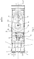
- the figures show an agricultural vehicle for collecting and possibly processing fibrous and/or granular products or any other fodder with a view to their distribution, said agricultural vehicle extending along a longitudinal axis X and comprising, on one on the one hand, a vehicle body 1 comprising a receiving and mixing tank 1a and a frame 1b supporting the tank 1a and, on the other hand, preferably at the front of the agricultural vehicle, a pick-up and transport unit 2, 3, 4 comprising a pick-up head 2, 3 and 4 comprising a pick-up member 2a, preferably a rotary pick-up member such as a rotary cutter, capable of picking up a product in the stored state, and a loading arm 3 equipped with a transfer device 4 capable of transporting said sampled product into the tank 1a.
- the overall width L1 of the pick-up member 2a is less than or equal to half the overall width L2 of the vehicle body 1.
- said overall width L1, respectively L2, of the sampling member 2a, respectively of the vehicle body 1, or of any other element of the agricultural vehicle corresponds to the maximum extent of the vehicle body 1, respectively of the sampling member 2a, or of said element concerned, measured in units of length, preferably in a unit of length of the international system such as the meter, in a direction perpendicular to the median plane, called the main median plane P, of the agricultural vehicle, said median plane containing the longitudinal axis X of said agricultural vehicle.
- the overall width L1 of the vehicle body can be determined without taking into consideration less essential parts than the tank 1a or the chassis 1b, such as for example sensors, which could protrude laterally from the tank 1a or the chassis 1b.
- the frame 1b can be a rolling frame 1b, that is to say equipped with wheels 10b allowing it to move on a surface S, as can be seen in the figure 1 .
- orientations are defined by considering such a vehicle resting or circulating on a horizontal surface S.
- perpendicular, respectively parallel employed subsequently must be understood as perpendicular or substantially perpendicular, respectively parallel or substantially parallel.
- Such an agricultural vehicle is an autonomous agricultural vehicle ( figure 1 , 2 and 3 ), that is to say robotic or automated, for example of the type disclosed in the document EP 2842411 .
- Such an autonomous agricultural vehicle as can be seen in the figure 1 , can comprise a central unit which can be housed in a box 9 fixed to the frame 1b, preferably close to the pick-up and transport unit 2, 3, 4.
- the box 9 can be positioned at the rear of the agricultural vehicle.
- the central unit may comprise all of the electronic circuits, for example a microprocessor and memories, and the computer program or programs recorded in the memory or memories, allowing the automatic operation of the agricultural vehicle, that is to say the automatic control of its movement/advance, for example in direction A, and/or automatic control of the pick-up and transport unit 2, 3 and 4, that is to say, in particular, automatic control of the operation of the loading arm 3 and/or of the picking member 2a according to predetermined sequences of displacement and/or speed of rotation of the picking member.
- the agricultural vehicle comprises drive and pivoting guide means 5a, 5b and the loading arm 3 can be mounted on the vehicle body 1, more particularly on the chassis 1a, being, thanks to said drive and guide in pivoting 5a, 5b movable in pivoting in a vertical plane so as to allow a vertical displacement of the sampling member 2a during the pivoting of the loading arm 3 about a pivot axis 5a horizontal and perpendicular to the median plane main P.
- the drive and pivoting means 5a, 5b can comprise said pivot axis 5a and at least one actuator 5b such as for example a hydraulic cylinder.
- the actuator 5b can be articulated on the vehicle body 1, more particularly on the chassis 1b, and on the loading arm 3.
- the loading arm 3 can thus be mounted on the vehicle body 1, more particularly on the chassis 1b, being movable in pivoting around the pivoting axis 5a and able to be driven in pivoting around the said pivoting axis 5a under the effect of the actuator 5b, for example between a low pivoting position and, shown in broken lines on the figure 1 , a high pivot position ( figure 1 ).
- the agricultural vehicle further comprises means for driving and guiding in translation 6a, 6b and the loading arm 3 is mounted on the body of the vehicle 1 while being movable in translation in a transverse direction T, perpendicular to the main median plane P , so as to allow transverse movement of the picking head 2 and its picking member 2a, that is to say in said transverse direction T, between a first end translation position defined by a first median plane P1, parallel to the main median plane P, of the picking head 2 or of the loading arm 3 and a second end translation position defined by a second median plane P2, parallel to the main median plane P, of the picking head 2 or of the loading arm 3.
- Such a transverse displacement of the loading arm 3 and more particularly of the member of the picking head 2 and its picking member 2a makes it possible to take the product from all or one large part of the overall width L2 of the vehicle body 1 without requiring the agricultural vehicle to be maneuvered to move the picking member 2a transversely and while obtaining at least the aforementioned advantages provided by the present invention.
- the means for driving and guiding in translation 6a, 6b can comprise at least one axis of translation 6a horizontal and perpendicular to the main median plane P, making it possible to guide the translation of the loading arm 3 mounted on said at least one axis of translation 6a and at least one actuator 6b, such as for example a hydraulic cylinder.
- the actuator 6b can be fixed on the frame 1b and the loading arm 3 parallel to the axis of translation 6a.
- the sampling of product is more precise since there is better control of the quantity of product loaded.
- the loading arm 3 can be moved twice or even three times laterally in the direction of translation T. In practice, it is of course, some overlap may be provided between a first and a second side-to-side translation position.
- the overall width L1 of the sampling member 2a may be less than or equal to half the distance D between the first median plane P1 and the second median plane P2.
- Such a value or reduction of the overall width L1 of the sampling member 2a makes it possible to work with more precision in terms of controlling the quantity to be loaded and makes it possible to work with less power consumption.
- Such an interval or ratio around half the distance D means that, without movement of the vehicle 2, four or five stages of translation of the sampling member 2a are sufficient to substantially cover the width of the agricultural vehicle, which makes it possible to limit the number of loading sequences while making it possible to optimize the precision of the loading and to reduce the power consumed due to a pick-up member 2a of reduced or narrow width.
- This embodiment combines precision and efficiency.
- the overall width L1 of the sampling member 2a may be less than or equal to half the distance D between the first median plane P1 and the second median plane P2 and be greater than or equal to one third, more preferably three- quarters, of the distance D between the first median plane P1 and the second median plane P2.
- Such an interval or ratio means that, without movement of the vehicle, three to four or five stages of translation are sufficient to substantially cover the width of the agricultural vehicle, which makes it possible to limit the number of loading sequences while making it possible to optimize the precision load and reduce power consumption. This embodiment combines even more precision and efficiency.
- the distance D between the first median plane P1 and the second median plane P2 can be less than or equal to the overall width L2 of the vehicle body 1.
- the translation of the loading arm 3 requires less time than repositioning the agricultural vehicle in a silo, the translation makes it possible to preserve the efficiency of the loading.
- the present invention can provide values other than these reduced preferential values of the overall width L1 of the sampling member 2a.
- the overall width L1 of the picking member 2a may be greater than half the distance D between the first median plane P1 and the second median plane P2 of the picking head 2 or of the loading arm 3 while being, according to the present invention, less than or equal to half the overall width L2 of the vehicle body 1.
- the overall width L1 may be between a quarter of the distance D and three-quarters of the distance D.
- the present invention can provide that the loading arm 3 can be movable in pivoting in a vertical plane and in horizontal translation transversely to the main median plane P ( figure 1 , 2 , 3 ).
- the autonomous mode of operation of the agricultural vehicle makes it possible to free up the space usually occupied, in current agricultural vehicles or machines, by the cockpit 7, generally located next to the loading arm 3, and to allow the transverse movement of the arm loading 3 in this space thus freed.
- the loading arm 3 on the one hand, can comprise a movable support 3a mounted in translation on the vehicle body 1, preferably on the chassis 1b, to allow its translational movement and, on the other hand, can be pivotally mounted on or in the movable support 3a to allow its pivoting, this at any point of its translational movement.
- the transfer device 4 can comprise a fitted outlet for the product, more particularly a junction platform 4a, making it possible to channel the outlet of the product transported by the transfer device 4 into the tank la which comprises for this purpose a receiving opening 10a to receive said product.
- the tank 1a can comprise two junction zones 8a, 8b forming a junction or a quasi-junction between the reception opening 10a, that is to say the edge 100a of the said reception opening 10a, and the said platform junction 4a to allow the reception of the product in the tank 1a through said reception opening 10a whatever the end translation position P1, P2 of the loading arm 3, namely a first junction zone 8a ensuring a first junction or quasi-junction between the receiving opening 10a and the junction platform 4a when the latter is at a point of translation corresponding to the first end translation position P1 of the loading arm 3 and a second junction zone 8b providing a second junction or quasi-junction between the receiving opening 10a and the junction platform 4a when the latter is at a translation point corresponding to the second translation position of ext part P2 of the loading arm 3.
- the transfer device 4 can extend along the loading arm 3.
- the transfer device 4 can comprise a transport member, such as for example a belt conveyor, not visible in the appended figures and the width overall dimensions of said transport member, in the case of a belt or belt conveyor, may be less than that of the member sampling 2a so as to allow a loading of the product in / on the transport member more efficient.
- the agricultural vehicle may include detection means, not shown in the appended figures, capable of detecting the presence of a user in the space surrounding the loading arm 3 and/or warning means, sound or light, making it possible to warn the user of his presence in this zone to encourage him to leave it.
- the tank 1a can contain one or more mixing screws 9a, 9b, preferably two mixing screws, similar or different from each other, or other tools for mixing or working the product in the tank 1a, which can be extend vertically into the latter.
Landscapes
- Life Sciences & Earth Sciences (AREA)
- Environmental Sciences (AREA)
- Birds (AREA)
- Animal Husbandry (AREA)
- Biodiversity & Conservation Biology (AREA)
- Control Of Position, Course, Altitude, Or Attitude Of Moving Bodies (AREA)
- Catching Or Destruction (AREA)
- Fertilizers (AREA)
- Fodder In General (AREA)
Claims (7)
- Landwirtschaftliches Fahrzeug zum Sammeln und eventuellen Aufbereiten von faserigen und/oder körnigen Produkten oder einer anderen Art von Futter für ihre Verteilung, wobei das landwirtschaftliche Fahrzeug ein autonomes landwirtschaftliches Fahrzeug ist, das sich entlang einer Längsachse (X) erstreckt und einerseits einen Fahrzeugkörper (1) umfasst, der einen Bottich (1a) zur Aufnahme und zum Mischen und ein den Bottich (1a) tragendes Fahrgestell (1b) aufweist, andererseits eine Entnahme- und Transporteinheit (2, 3, 4), die einen Entnahmekopf (2) umfasst, der mit einem Organ zur Entnahme (2a) des Produkts versehen ist, vorzugsweise einem drehbaren Entnahmeorgan, das aus einer drehbaren Fräse besteht, und einen Ladearm (3), der mit einer Transfervorrichtung (4) ausgestattet ist, die geeignet ist, das entnommene Produkt bis in den Bottich (1a) zu transportieren, und andererseits Schwenkantriebs- und -führungsmittel (5a, 5b), wobei der Ladearm (3) am Fahrzeugkörper (1) so angebracht ist, dass er dank der Schwenkantriebs- und -führungsmittel (5a, 5b) in einer vertikalen Ebene um eine horizontale und zur Hauptmittelebene (P) senkrechte Schwenkachse (5a) schwenkbeweglich ist, um eine vertikale Verlagerung des Entnahmeorgans (2a) bei der Schwenkung des Ladearmes (3) zu ermöglichen,
wobei das landwirtschaftliche Fahrzeug gekennzeichnet ist:- dadurch, dass die Gesamtbreite (L1) des Entnahmeorgans (2a) kleiner oder gleich der Hälfte der Gesamtbreite (L2) des Fahrzeugkörpers (1) ist, wobei die Gesamtbreite (L1, L2) als die maximale Erstreckung des Fahrzeugkörpers (1) bzw. des Entnahmeorgans (2a) definiert ist, gemessen in Längeneinheiten in einer Richtung, die zu der Mittelebene des landwirtschaftlichen Fahrzeugs, die seine Längsachse (X) enthält, Hauptmittelebene (P) genannt, senkrecht ist,- dadurch, dass es Translationsantriebs- und- führungsmittel (6a, 6b) umfasst, und dadurch, dass der Ladearm (3) am Fahrzeugkörper (1) so angebracht ist, dass er dank der Translationsantriebs- und -führungsmittel (6a, 6b) in einer zur Hauptmittelebene (P) senkrechten Querrichtung (T) translatorisch beweglich ist, um eine Querverlagerung des Entnahmekopfes (2) und seines Entnahmeorgans (2a), d. h. in der Querrichtung (T), zwischen einer ersten Endposition der Translation des Entnahmekopfes (2) oder des Ladearmes (3), die durch eine zur Hauptmittelebene (P) parallele erste Mittelebene (P1) definiert ist, und einer zweiten Endposition der Translation des Entnahmekopfes (2) oder des Ladearmes (3), die durch eine zur Hauptmittelebene (P) parallele zweite Mittelebene (P2) definiert ist, zu ermöglichen. - Landwirtschaftliches Fahrzeug nach Anspruch 1, dadurch gekennzeichnet, dass die Gesamtbreite (L1) des Entnahmeorgans (2a) kleiner oder gleich der Hälfte des Abstands (D) zwischen der ersten Mittelebene (P1) und der zweiten Mittelebene (P2) ist.
- Landwirtschaftliches Fahrzeug nach Anspruch 1 oder 2, dadurch gekennzeichnet, dass die Gesamtbreite (L1) des Entnahmeorgans (2a) kleiner als die Hälfte des Abstands (D) zwischen der ersten Mittelebene (P1) und der zweiten Mittelebene (P2) ist und größer oder gleich einem Drittel des Abstands (D) zwischen der ersten Mittelebene (P1) und der zweiten Mittelebene (P2) ist.
- Landwirtschaftliches Fahrzeug nach einem der Ansprüche 1 bis 3, dadurch gekennzeichnet, dass der Ladearm (3) einerseits einen beweglichen Träger (3a) umfasst, der translatorisch verschiebbar am Fahrzeugkörper (1) angebracht ist, um seine Translation zu ermöglichen, und andererseits auf dem beweglichen Träger (3a) schwenkbar gelagert ist, um seine Schwenkung an jedem beliebigen Punkt seiner Translation zu ermöglichen.
- Landwirtschaftliches Fahrzeug nach einem der Ansprüche 1 bis 4, dadurch gekennzeichnet, dass die Transfervorrichtung (4) eine Verbindungsplattform (4a) umfasst, die es ermöglicht, den Austritt des von der Transfervorrichtung (4) transportierten Produkts bis in den Bottich (1a) zu kanalisieren, welcher zu diesem Zweck eine Aufnahmeöffnung (10a) für das Produkt umfasst, und dadurch, dass der Bottich (1a) zwei Verbindungsbereiche (8a, 8b) umfasst, die eine Verbindung oder eine Quasiverbindung zwischen seiner Aufnahmeöffnung (10a) und der Verbindungsplattform (4a) herstellen, um die Aufnahme des Produkts in den Bottich (1a) unabhängig von der Endposition (P1, P2) der Translation des Ladearmes (3) zu ermöglichen, nämlich einen ersten Verbindungsbereich (8a), der eine erste Verbindung oder Quasiverbindung zwischen der Aufnahmeöffnung (10a) und der Verbindungsplattform (4a) sicherstellt, wenn diese sich in einem Translationspunkt befindet, welcher der ersten Endposition der Translation des Ladearmes (3) entspricht, und einen zweiten Verbindungsbereich (8b), der eine zweite Verbindung oder Quasiverbindung zwischen der Aufnahmeöffnung (10a) und der Verbindungsplattform (4a) sicherstellt, wenn diese sich in einem Translationspunkt befindet, welcher der zweiten Endposition (P2) der Translation des Ladearmes (3) entspricht.
- Landwirtschaftliches Fahrzeug nach einem der Ansprüche 1 bis 5, dadurch gekennzeichnet, dass die Transfervorrichtung (4) ein Transportorgan wie etwa ein Förderband umfasst, und dadurch, dass die Gesamtbreite des Transportorgans kleiner als diejenige des Entnahmeorgans (2a) ist.
- Landwirtschaftliches Fahrzeug nach einem der Ansprüche 1 bis 6, dadurch gekennzeichnet, dass es Erkennungsmittel, die geeignet sind, die Anwesenheit eines Benutzers wenigstens in einem den Ladearm (3) umgebenden Bereich zu erkennen, und/oder akustische oder optische Warnmittel umfasst.
Applications Claiming Priority (1)
| Application Number | Priority Date | Filing Date | Title |
|---|---|---|---|
| FR1855574A FR3082699B1 (fr) | 2018-06-22 | 2018-06-22 | Vehicule agricole pour collecter et, eventuellement traiter, des produits fibreux et/ou granulaires ou tout autre fourrage en vue de leur distribution |
Publications (2)
| Publication Number | Publication Date |
|---|---|
| EP3586604A1 EP3586604A1 (de) | 2020-01-01 |
| EP3586604B1 true EP3586604B1 (de) | 2022-08-03 |
Family
ID=63557647
Family Applications (1)
| Application Number | Title | Priority Date | Filing Date |
|---|---|---|---|
| EP19180546.4A Active EP3586604B1 (de) | 2018-06-22 | 2019-06-17 | Landwirtschaftliches fahrzeug zum sammeln und eventuellen aufbereiten von faserigen und/oder körnigen produkten oder einer anderen art von futter für ihre verteilung |
Country Status (3)
| Country | Link |
|---|---|
| EP (1) | EP3586604B1 (de) |
| ES (1) | ES2930083T3 (de) |
| FR (1) | FR3082699B1 (de) |
Families Citing this family (3)
| Publication number | Priority date | Publication date | Assignee | Title |
|---|---|---|---|---|
| FR3113998B1 (fr) | 2020-09-14 | 2022-09-09 | Kuhn Audureau S A S | Procédé permettant une détection fiable du bord supérieur du front d’attaque d’un tas de produit(s) pour l’alimentation animale, à partir d’un véhicule de prélèvement et un tel véhicule permettant la mise en œuvre dudit procédé |
| FR3123780B1 (fr) | 2021-06-10 | 2023-10-27 | Kuhn Audureau Sas | Procédé de vérification de la qualité de service d’une installation d’alimentation pour animaux d’élevage et une telle installation d’alimentation |
| EP4702836A1 (de) * | 2024-09-03 | 2026-03-04 | Faresin Industries SpA | Elektrischer mischwagen, verfahren zur steuerung eines tierfütterungsprozesses mit hilfe eines solchen mischwagens und computerprogramm, das dieses steuerverfahren ausführt |
Family Cites Families (6)
| Publication number | Priority date | Publication date | Assignee | Title |
|---|---|---|---|---|
| DE9005280U1 (de) * | 1990-05-09 | 1990-07-12 | Völk Maschinenbau GmbH, 8910 Landsberg | Flachsilofräs- und Fördereinrichtung |
| DE29611851U1 (de) * | 1996-07-06 | 1996-09-19 | B. Strautmann & Söhne GmbH u. Co, 49196 Bad Laer | Vorrichtung zur Aufnahme von Silage-Futter |
| DE29715066U1 (de) * | 1997-08-22 | 1997-10-30 | Hirl, Alois, 84326 Falkenberg | Landwirtschaftlicher Selbstfahrer |
| NL2011343C2 (en) * | 2013-08-27 | 2015-03-02 | Beheermij Schuitemaker B V | Silage cutting head, silage collector and silage transport vehicle. |
| DE202014003600U1 (de) * | 2014-05-03 | 2014-06-12 | Hirl Misch- und Anlagentechnik GmbH & Co. KG | Futtermischer |
| DE102014116882B4 (de) * | 2014-11-18 | 2018-05-24 | B. Strautmann & Söhne GmbH u. Co. KG | Verfahren zur Entnahme von Futtermitteln aus Fahrsilos |
-
2018
- 2018-06-22 FR FR1855574A patent/FR3082699B1/fr not_active Expired - Fee Related
-
2019
- 2019-06-17 EP EP19180546.4A patent/EP3586604B1/de active Active
- 2019-06-17 ES ES19180546T patent/ES2930083T3/es active Active
Also Published As
| Publication number | Publication date |
|---|---|
| FR3082699B1 (fr) | 2020-12-25 |
| FR3082699A1 (fr) | 2019-12-27 |
| EP3586604A1 (de) | 2020-01-01 |
| ES2930083T3 (es) | 2022-12-07 |
Similar Documents
| Publication | Publication Date | Title |
|---|---|---|
| EP3586604B1 (de) | Landwirtschaftliches fahrzeug zum sammeln und eventuellen aufbereiten von faserigen und/oder körnigen produkten oder einer anderen art von futter für ihre verteilung | |
| FR2978897A1 (fr) | Installation de coupe pour la coupe de vegetaux a tige verticale, tels que du chanvre, et moissonneuse-batteuse a chassis roulant equipe a l'avant d'une telle installation de coupe | |
| EP2871930B1 (de) | Verteilmaschine | |
| EP3033938B1 (de) | Strohabwickel- und -verteilungsvorrichtung | |
| EP3328190B1 (de) | Selbstfahrender wagen zum anschieben von strohfutter | |
| FR3017026A1 (fr) | Machine agricole comportant une ouverture perfectionnee entre une cuve de melange et un carter d'ejection des produits | |
| EP3890468B1 (de) | Maschine zum lösen und ausgeben von ballen aus tierstreu oder futterballen | |
| EP3935934B1 (de) | Landwirtschaftliches gerät mit einem mähbalken und einem abnehmbaren kollektor und landwirtschaftliche maschine mit einem solchen gerät | |
| FR2522245A1 (fr) | Materiel agricole pour la recolte de fruits et ensembles recepteurs constitutifs dudit materiel | |
| FR3055512A1 (fr) | Machine agricole munie d'un dispositif perfectionne de transfert de produit preleve | |
| BE1017306A3 (fr) | Godet de chargement et de dechargement. | |
| EP0704156B1 (de) | Gerät zum Ausgeben von Nahrungsmitteln oder Halmgut für Tiere, insbesondere von Silage | |
| EP1405557B1 (de) | Verteilmaschine | |
| FR2618047A1 (fr) | Machine agricole polyvalente utilisable comme desileuse, distributrice, derouleuse, pailleuse, melangeuse et recolteuse-chargeuse | |
| EP3297428B1 (de) | Schaufel zur aufnahme und zur verteilung, versehen mit verbesserten auflockermitteln | |
| FR2741777A1 (fr) | Dispositif de distribution et de paillage | |
| WO2002055275A1 (fr) | Engin pour la coupe ou le ramassage de rondins et leur fendage en buches de bois de chauffage | |
| EP4005374B1 (de) | Mischer mit einer zweiteiligen auslassöffnung | |
| FR3008112A1 (fr) | Dispositif remorque permettant de nettoyer toute surface en ramassant les detritus sur le sol par brossage, comportant une caisse de chargement a l avant et un bloc de ramassage a l arriere | |
| FR2998517A1 (fr) | Remorque autochargeuse a attelage telescopique | |
| EP3469885A1 (de) | Zylindrische rolle mit zwei teilen mit klinge und landwirtschaftliche maschine mit eine solche rolle | |
| FR2768296A1 (fr) | Machine coupante pour vegetaux a evacuation axiale et a turbine basculante | |
| EP1149527A2 (de) | Landmaschine zum Verteilen von Produkten | |
| FR2782889A1 (fr) | Machine pour distribuer de la matiere vegetale mise sous forme de balle | |
| BE886557A (fr) | Autochargeuse pour fourrages |
Legal Events
| Date | Code | Title | Description |
|---|---|---|---|
| PUAI | Public reference made under article 153(3) epc to a published international application that has entered the european phase |
Free format text: ORIGINAL CODE: 0009012 |
|
| STAA | Information on the status of an ep patent application or granted ep patent |
Free format text: STATUS: THE APPLICATION HAS BEEN PUBLISHED |
|
| AK | Designated contracting states |
Kind code of ref document: A1 Designated state(s): AL AT BE BG CH CY CZ DE DK EE ES FI FR GB GR HR HU IE IS IT LI LT LU LV MC MK MT NL NO PL PT RO RS SE SI SK SM TR |
|
| AX | Request for extension of the european patent |
Extension state: BA ME |
|
| STAA | Information on the status of an ep patent application or granted ep patent |
Free format text: STATUS: REQUEST FOR EXAMINATION WAS MADE |
|
| RAP1 | Party data changed (applicant data changed or rights of an application transferred) |
Owner name: KUHN-AUDUREAU SAS |
|
| 17P | Request for examination filed |
Effective date: 20200625 |
|
| RBV | Designated contracting states (corrected) |
Designated state(s): AL AT BE BG CH CY CZ DE DK EE ES FI FR GB GR HR HU IE IS IT LI LT LU LV MC MK MT NL NO PL PT RO RS SE SI SK SM TR |
|
| STAA | Information on the status of an ep patent application or granted ep patent |
Free format text: STATUS: EXAMINATION IS IN PROGRESS |
|
| 17Q | First examination report despatched |
Effective date: 20210204 |
|
| REG | Reference to a national code |
Ref country code: DE Ref legal event code: R079 Ref document number: 602019017679 Country of ref document: DE Free format text: PREVIOUS MAIN CLASS: A01F0025200000 Ipc: A01K0005000000 |
|
| GRAP | Despatch of communication of intention to grant a patent |
Free format text: ORIGINAL CODE: EPIDOSNIGR1 |
|
| STAA | Information on the status of an ep patent application or granted ep patent |
Free format text: STATUS: GRANT OF PATENT IS INTENDED |
|
| RIC1 | Information provided on ipc code assigned before grant |
Ipc: A01F 25/20 20060101ALI20210915BHEP Ipc: A01K 5/00 20060101AFI20210915BHEP |
|
| INTG | Intention to grant announced |
Effective date: 20211007 |
|
| GRAJ | Information related to disapproval of communication of intention to grant by the applicant or resumption of examination proceedings by the epo deleted |
Free format text: ORIGINAL CODE: EPIDOSDIGR1 |
|
| STAA | Information on the status of an ep patent application or granted ep patent |
Free format text: STATUS: EXAMINATION IS IN PROGRESS |
|
| GRAS | Grant fee paid |
Free format text: ORIGINAL CODE: EPIDOSNIGR3 |
|
| STAA | Information on the status of an ep patent application or granted ep patent |
Free format text: STATUS: GRANT OF PATENT IS INTENDED |
|
| GRAP | Despatch of communication of intention to grant a patent |
Free format text: ORIGINAL CODE: EPIDOSNIGR1 |
|
| INTC | Intention to grant announced (deleted) | ||
| INTG | Intention to grant announced |
Effective date: 20220223 |
|
| GRAA | (expected) grant |
Free format text: ORIGINAL CODE: 0009210 |
|
| STAA | Information on the status of an ep patent application or granted ep patent |
Free format text: STATUS: THE PATENT HAS BEEN GRANTED |
|
| AK | Designated contracting states |
Kind code of ref document: B1 Designated state(s): AL AT BE BG CH CY CZ DE DK EE ES FI FR GB GR HR HU IE IS IT LI LT LU LV MC MK MT NL NO PL PT RO RS SE SI SK SM TR |
|
| REG | Reference to a national code |
Ref country code: AT Ref legal event code: REF Ref document number: 1508008 Country of ref document: AT Kind code of ref document: T Effective date: 20220815 Ref country code: CH Ref legal event code: EP |
|
| REG | Reference to a national code |
Ref country code: DE Ref legal event code: R096 Ref document number: 602019017679 Country of ref document: DE |
|
| REG | Reference to a national code |
Ref country code: IE Ref legal event code: FG4D Free format text: LANGUAGE OF EP DOCUMENT: FRENCH |
|
| REG | Reference to a national code |
Ref country code: NL Ref legal event code: FP |
|
| REG | Reference to a national code |
Ref country code: LT Ref legal event code: MG9D |
|
| REG | Reference to a national code |
Ref country code: ES Ref legal event code: FG2A Ref document number: 2930083 Country of ref document: ES Kind code of ref document: T3 Effective date: 20221207 |
|
| PG25 | Lapsed in a contracting state [announced via postgrant information from national office to epo] |
Ref country code: SE Free format text: LAPSE BECAUSE OF FAILURE TO SUBMIT A TRANSLATION OF THE DESCRIPTION OR TO PAY THE FEE WITHIN THE PRESCRIBED TIME-LIMIT Effective date: 20220803 Ref country code: RS Free format text: LAPSE BECAUSE OF FAILURE TO SUBMIT A TRANSLATION OF THE DESCRIPTION OR TO PAY THE FEE WITHIN THE PRESCRIBED TIME-LIMIT Effective date: 20220803 Ref country code: PT Free format text: LAPSE BECAUSE OF FAILURE TO SUBMIT A TRANSLATION OF THE DESCRIPTION OR TO PAY THE FEE WITHIN THE PRESCRIBED TIME-LIMIT Effective date: 20221205 Ref country code: NO Free format text: LAPSE BECAUSE OF FAILURE TO SUBMIT A TRANSLATION OF THE DESCRIPTION OR TO PAY THE FEE WITHIN THE PRESCRIBED TIME-LIMIT Effective date: 20221103 Ref country code: LV Free format text: LAPSE BECAUSE OF FAILURE TO SUBMIT A TRANSLATION OF THE DESCRIPTION OR TO PAY THE FEE WITHIN THE PRESCRIBED TIME-LIMIT Effective date: 20220803 Ref country code: LT Free format text: LAPSE BECAUSE OF FAILURE TO SUBMIT A TRANSLATION OF THE DESCRIPTION OR TO PAY THE FEE WITHIN THE PRESCRIBED TIME-LIMIT Effective date: 20220803 Ref country code: FI Free format text: LAPSE BECAUSE OF FAILURE TO SUBMIT A TRANSLATION OF THE DESCRIPTION OR TO PAY THE FEE WITHIN THE PRESCRIBED TIME-LIMIT Effective date: 20220803 |
|
| PG25 | Lapsed in a contracting state [announced via postgrant information from national office to epo] |
Ref country code: PL Free format text: LAPSE BECAUSE OF FAILURE TO SUBMIT A TRANSLATION OF THE DESCRIPTION OR TO PAY THE FEE WITHIN THE PRESCRIBED TIME-LIMIT Effective date: 20220803 Ref country code: IS Free format text: LAPSE BECAUSE OF FAILURE TO SUBMIT A TRANSLATION OF THE DESCRIPTION OR TO PAY THE FEE WITHIN THE PRESCRIBED TIME-LIMIT Effective date: 20221203 Ref country code: HR Free format text: LAPSE BECAUSE OF FAILURE TO SUBMIT A TRANSLATION OF THE DESCRIPTION OR TO PAY THE FEE WITHIN THE PRESCRIBED TIME-LIMIT Effective date: 20220803 Ref country code: GR Free format text: LAPSE BECAUSE OF FAILURE TO SUBMIT A TRANSLATION OF THE DESCRIPTION OR TO PAY THE FEE WITHIN THE PRESCRIBED TIME-LIMIT Effective date: 20221104 |
|
| PG25 | Lapsed in a contracting state [announced via postgrant information from national office to epo] |
Ref country code: SM Free format text: LAPSE BECAUSE OF FAILURE TO SUBMIT A TRANSLATION OF THE DESCRIPTION OR TO PAY THE FEE WITHIN THE PRESCRIBED TIME-LIMIT Effective date: 20220803 Ref country code: RO Free format text: LAPSE BECAUSE OF FAILURE TO SUBMIT A TRANSLATION OF THE DESCRIPTION OR TO PAY THE FEE WITHIN THE PRESCRIBED TIME-LIMIT Effective date: 20220803 Ref country code: DK Free format text: LAPSE BECAUSE OF FAILURE TO SUBMIT A TRANSLATION OF THE DESCRIPTION OR TO PAY THE FEE WITHIN THE PRESCRIBED TIME-LIMIT Effective date: 20220803 Ref country code: CZ Free format text: LAPSE BECAUSE OF FAILURE TO SUBMIT A TRANSLATION OF THE DESCRIPTION OR TO PAY THE FEE WITHIN THE PRESCRIBED TIME-LIMIT Effective date: 20220803 |
|
| REG | Reference to a national code |
Ref country code: DE Ref legal event code: R097 Ref document number: 602019017679 Country of ref document: DE |
|
| PG25 | Lapsed in a contracting state [announced via postgrant information from national office to epo] |
Ref country code: SK Free format text: LAPSE BECAUSE OF FAILURE TO SUBMIT A TRANSLATION OF THE DESCRIPTION OR TO PAY THE FEE WITHIN THE PRESCRIBED TIME-LIMIT Effective date: 20220803 Ref country code: EE Free format text: LAPSE BECAUSE OF FAILURE TO SUBMIT A TRANSLATION OF THE DESCRIPTION OR TO PAY THE FEE WITHIN THE PRESCRIBED TIME-LIMIT Effective date: 20220803 |
|
| PLBE | No opposition filed within time limit |
Free format text: ORIGINAL CODE: 0009261 |
|
| STAA | Information on the status of an ep patent application or granted ep patent |
Free format text: STATUS: NO OPPOSITION FILED WITHIN TIME LIMIT |
|
| PG25 | Lapsed in a contracting state [announced via postgrant information from national office to epo] |
Ref country code: AL Free format text: LAPSE BECAUSE OF FAILURE TO SUBMIT A TRANSLATION OF THE DESCRIPTION OR TO PAY THE FEE WITHIN THE PRESCRIBED TIME-LIMIT Effective date: 20220803 |
|
| 26N | No opposition filed |
Effective date: 20230504 |
|
| P01 | Opt-out of the competence of the unified patent court (upc) registered |
Effective date: 20230622 |
|
| REG | Reference to a national code |
Ref country code: AT Ref legal event code: UEP Ref document number: 1508008 Country of ref document: AT Kind code of ref document: T Effective date: 20220803 |
|
| PG25 | Lapsed in a contracting state [announced via postgrant information from national office to epo] |
Ref country code: SI Free format text: LAPSE BECAUSE OF FAILURE TO SUBMIT A TRANSLATION OF THE DESCRIPTION OR TO PAY THE FEE WITHIN THE PRESCRIBED TIME-LIMIT Effective date: 20220803 |
|
| PG25 | Lapsed in a contracting state [announced via postgrant information from national office to epo] |
Ref country code: MC Free format text: LAPSE BECAUSE OF FAILURE TO SUBMIT A TRANSLATION OF THE DESCRIPTION OR TO PAY THE FEE WITHIN THE PRESCRIBED TIME-LIMIT Effective date: 20220803 |
|
| PG25 | Lapsed in a contracting state [announced via postgrant information from national office to epo] |
Ref country code: MC Free format text: LAPSE BECAUSE OF FAILURE TO SUBMIT A TRANSLATION OF THE DESCRIPTION OR TO PAY THE FEE WITHIN THE PRESCRIBED TIME-LIMIT Effective date: 20220803 |
|
| REG | Reference to a national code |
Ref country code: CH Ref legal event code: PL |
|
| REG | Reference to a national code |
Ref country code: BE Ref legal event code: MM Effective date: 20230630 |
|
| PG25 | Lapsed in a contracting state [announced via postgrant information from national office to epo] |
Ref country code: LU Free format text: LAPSE BECAUSE OF NON-PAYMENT OF DUE FEES Effective date: 20230617 |
|
| PG25 | Lapsed in a contracting state [announced via postgrant information from national office to epo] |
Ref country code: LU Free format text: LAPSE BECAUSE OF NON-PAYMENT OF DUE FEES Effective date: 20230617 |
|
| PG25 | Lapsed in a contracting state [announced via postgrant information from national office to epo] |
Ref country code: CH Free format text: LAPSE BECAUSE OF NON-PAYMENT OF DUE FEES Effective date: 20230630 |
|
| PG25 | Lapsed in a contracting state [announced via postgrant information from national office to epo] |
Ref country code: BE Free format text: LAPSE BECAUSE OF NON-PAYMENT OF DUE FEES Effective date: 20230630 |
|
| PG25 | Lapsed in a contracting state [announced via postgrant information from national office to epo] |
Ref country code: BG Free format text: LAPSE BECAUSE OF FAILURE TO SUBMIT A TRANSLATION OF THE DESCRIPTION OR TO PAY THE FEE WITHIN THE PRESCRIBED TIME-LIMIT Effective date: 20220803 |
|
| PG25 | Lapsed in a contracting state [announced via postgrant information from national office to epo] |
Ref country code: BG Free format text: LAPSE BECAUSE OF FAILURE TO SUBMIT A TRANSLATION OF THE DESCRIPTION OR TO PAY THE FEE WITHIN THE PRESCRIBED TIME-LIMIT Effective date: 20220803 |
|
| PGFP | Annual fee paid to national office [announced via postgrant information from national office to epo] |
Ref country code: DE Payment date: 20250627 Year of fee payment: 7 |
|
| PGFP | Annual fee paid to national office [announced via postgrant information from national office to epo] |
Ref country code: GB Payment date: 20250627 Year of fee payment: 7 |
|
| PGFP | Annual fee paid to national office [announced via postgrant information from national office to epo] |
Ref country code: NL Payment date: 20250626 Year of fee payment: 7 |
|
| PGFP | Annual fee paid to national office [announced via postgrant information from national office to epo] |
Ref country code: FR Payment date: 20250625 Year of fee payment: 7 |
|
| PGFP | Annual fee paid to national office [announced via postgrant information from national office to epo] |
Ref country code: AT Payment date: 20250603 Year of fee payment: 7 |
|
| PG25 | Lapsed in a contracting state [announced via postgrant information from national office to epo] |
Ref country code: CY Free format text: LAPSE BECAUSE OF FAILURE TO SUBMIT A TRANSLATION OF THE DESCRIPTION OR TO PAY THE FEE WITHIN THE PRESCRIBED TIME-LIMIT; INVALID AB INITIO Effective date: 20190617 |
|
| PGFP | Annual fee paid to national office [announced via postgrant information from national office to epo] |
Ref country code: IE Payment date: 20250627 Year of fee payment: 7 |
|
| PG25 | Lapsed in a contracting state [announced via postgrant information from national office to epo] |
Ref country code: HU Free format text: LAPSE BECAUSE OF FAILURE TO SUBMIT A TRANSLATION OF THE DESCRIPTION OR TO PAY THE FEE WITHIN THE PRESCRIBED TIME-LIMIT; INVALID AB INITIO Effective date: 20190617 |
|
| PGFP | Annual fee paid to national office [announced via postgrant information from national office to epo] |
Ref country code: ES Payment date: 20250701 Year of fee payment: 7 |
|
| PGFP | Annual fee paid to national office [announced via postgrant information from national office to epo] |
Ref country code: IT Payment date: 20250619 Year of fee payment: 7 |
|
| PG25 | Lapsed in a contracting state [announced via postgrant information from national office to epo] |
Ref country code: TR Free format text: LAPSE BECAUSE OF FAILURE TO SUBMIT A TRANSLATION OF THE DESCRIPTION OR TO PAY THE FEE WITHIN THE PRESCRIBED TIME-LIMIT Effective date: 20220803 |