EP2897809B1 - Trocknungsanordnung für einen drucker und steuerungsverfahren für eine trocknungsanordnung für einen drucker. - Google Patents
Trocknungsanordnung für einen drucker und steuerungsverfahren für eine trocknungsanordnung für einen drucker. Download PDFInfo
- Publication number
- EP2897809B1 EP2897809B1 EP12885138.3A EP12885138A EP2897809B1 EP 2897809 B1 EP2897809 B1 EP 2897809B1 EP 12885138 A EP12885138 A EP 12885138A EP 2897809 B1 EP2897809 B1 EP 2897809B1
- Authority
- EP
- European Patent Office
- Prior art keywords
- fan
- temperature
- control signal
- drying assembly
- pwm
- Prior art date
- Legal status (The legal status is an assumption and is not a legal conclusion. Google has not performed a legal analysis and makes no representation as to the accuracy of the status listed.)
- Active
Links
Images


Classifications
-
- B—PERFORMING OPERATIONS; TRANSPORTING
- B41—PRINTING; LINING MACHINES; TYPEWRITERS; STAMPS
- B41J—TYPEWRITERS; SELECTIVE PRINTING MECHANISMS, i.e. MECHANISMS PRINTING OTHERWISE THAN FROM A FORME; CORRECTION OF TYPOGRAPHICAL ERRORS
- B41J11/00—Devices or arrangements of selective printing mechanisms, e.g. ink-jet printers or thermal printers, for supporting or handling copy material in sheet or web form
- B41J11/0015—Devices or arrangements of selective printing mechanisms, e.g. ink-jet printers or thermal printers, for supporting or handling copy material in sheet or web form for treating before, during or after printing or for uniform coating or laminating the copy material before or after printing
- B41J11/002—Curing or drying the ink on the copy materials, e.g. by heating or irradiating
- B41J11/0022—Curing or drying the ink on the copy materials, e.g. by heating or irradiating using convection means, e.g. by using a fan for blowing or sucking air
-
- B—PERFORMING OPERATIONS; TRANSPORTING
- B41—PRINTING; LINING MACHINES; TYPEWRITERS; STAMPS
- B41F—PRINTING MACHINES OR PRESSES
- B41F23/00—Devices for treating the surfaces of sheets, webs, or other articles in connection with printing
- B41F23/04—Devices for treating the surfaces of sheets, webs, or other articles in connection with printing by heat drying, by cooling, by applying powders
-
- B—PERFORMING OPERATIONS; TRANSPORTING
- B41—PRINTING; LINING MACHINES; TYPEWRITERS; STAMPS
- B41J—TYPEWRITERS; SELECTIVE PRINTING MECHANISMS, i.e. MECHANISMS PRINTING OTHERWISE THAN FROM A FORME; CORRECTION OF TYPOGRAPHICAL ERRORS
- B41J11/00—Devices or arrangements of selective printing mechanisms, e.g. ink-jet printers or thermal printers, for supporting or handling copy material in sheet or web form
- B41J11/0015—Devices or arrangements of selective printing mechanisms, e.g. ink-jet printers or thermal printers, for supporting or handling copy material in sheet or web form for treating before, during or after printing or for uniform coating or laminating the copy material before or after printing
- B41J11/002—Curing or drying the ink on the copy materials, e.g. by heating or irradiating
- B41J11/0022—Curing or drying the ink on the copy materials, e.g. by heating or irradiating using convection means, e.g. by using a fan for blowing or sucking air
- B41J11/00222—Controlling the convection means
-
- B—PERFORMING OPERATIONS; TRANSPORTING
- B41—PRINTING; LINING MACHINES; TYPEWRITERS; STAMPS
- B41J—TYPEWRITERS; SELECTIVE PRINTING MECHANISMS, i.e. MECHANISMS PRINTING OTHERWISE THAN FROM A FORME; CORRECTION OF TYPOGRAPHICAL ERRORS
- B41J2/00—Typewriters or selective printing mechanisms characterised by the printing or marking process for which they are designed
- B41J2/005—Typewriters or selective printing mechanisms characterised by the printing or marking process for which they are designed characterised by bringing liquid or particles selectively into contact with a printing material
- B41J2/01—Ink jet
- B41J2/015—Ink jet characterised by the jet generation process
- B41J2/04—Ink jet characterised by the jet generation process generating single droplets or particles on demand
- B41J2/045—Ink jet characterised by the jet generation process generating single droplets or particles on demand by pressure, e.g. electromechanical transducers
- B41J2/05—Ink jet characterised by the jet generation process generating single droplets or particles on demand by pressure, e.g. electromechanical transducers produced by the application of heat
-
- B—PERFORMING OPERATIONS; TRANSPORTING
- B41—PRINTING; LINING MACHINES; TYPEWRITERS; STAMPS
- B41J—TYPEWRITERS; SELECTIVE PRINTING MECHANISMS, i.e. MECHANISMS PRINTING OTHERWISE THAN FROM A FORME; CORRECTION OF TYPOGRAPHICAL ERRORS
- B41J23/00—Power drives for actions or mechanisms
- B41J23/02—Mechanical power drives
- B41J23/04—Mechanical power drives with driven mechanism arranged to be clutched to continuously- operating power source
-
- B—PERFORMING OPERATIONS; TRANSPORTING
- B41—PRINTING; LINING MACHINES; TYPEWRITERS; STAMPS
- B41J—TYPEWRITERS; SELECTIVE PRINTING MECHANISMS, i.e. MECHANISMS PRINTING OTHERWISE THAN FROM A FORME; CORRECTION OF TYPOGRAPHICAL ERRORS
- B41J29/00—Details of, or accessories for, typewriters or selective printing mechanisms not otherwise provided for
- B41J29/377—Cooling or ventilating arrangements
-
- F—MECHANICAL ENGINEERING; LIGHTING; HEATING; WEAPONS; BLASTING
- F26—DRYING
- F26B—DRYING SOLID MATERIALS OR OBJECTS BY REMOVING LIQUID THEREFROM
- F26B21/00—Arrangements for supplying or controlling air or other gases for drying solid materials or objects
- F26B21/30—Controlling, e.g. regulating, parameters of gas supply
- F26B21/35—Temperature; Pressure
-
- F—MECHANICAL ENGINEERING; LIGHTING; HEATING; WEAPONS; BLASTING
- F26—DRYING
- F26B—DRYING SOLID MATERIALS OR OBJECTS BY REMOVING LIQUID THEREFROM
- F26B21/00—Arrangements for supplying or controlling air or other gases for drying solid materials or objects
- F26B21/50—Ducting arrangements from the source of air or other gases to the materials or objects being dried
Definitions
- Figure 1 is a side view of an example printer 100.
- the printer comprises media supply system 102, media 104, inkjet print bar 106 and drying assembly 108.
- media 104 is a continuous sheet supplied by media supply system 102.
- media may comprise individual sheets.
- Media 104 is fed from media supply system 102 underneath print bar 106.
- Inkjet heads on print bar 106 deposit ink onto media 104.
- the media passes underneath the drying assembly 108. Drying assembly 108 forces heated air past media 104 as shown by arrow 110. The heated air dries and cures the ink deposited onto the media.
- Print bar 106 may also deposit additional compounds onto media, for example gloss coats and the like.
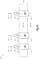
- FIG. 2A is a block diagram of drying assembly 108.
- Drying assembly comprises N fan units, where N is an integer greater than 1.
- Each fan unit comprises a fan housing 212, a fan 214, a heating element 216 and a temperature sensor 218.
- the fan units are attached to support 220 in a spaced apart relationship.
- Each fan 214 is located inside a fan housing 212 and forces air in the direction shown by arrow 110.
- the heating elements 216 may also be located inside the fan housings 212.
- the heating elements 216 heat the air moved by the fans 214.
- the temperature sensors 218 are located near the fan exhaust and can monitor the temperature of the air as it leaves each fan housing 212.
- Figure 2B is an isometric view of drying assembly 108.
- the fan units are spaced apart by distance X, where distance X is 425.6 mm.
- distance X is 425.6 mm.
- the speed of each fan can be controlled independently.
- the fan speeds are adjusted with a fan speed control signal, typically a pulse width modulation (PWM) signal.
- PWM pulse width modulation
- the temperatures of the heating elements are controlled with a heating element control signal.
- a single heating element control signal is used for all of the heating elements.
- each of the N heating elements may have some resistance variability.
- each of the N fans may run at a slightly different speed given the same input signal. Due to these variations, the air temperature exiting each fan may be different even with the same input control signals (i.e. the fan speed control signal and the heating element control signal). The variation in air temperature can cause uneven curing and drying across the page.
- the controller reads each temperature sensor to determine the air temperature at each fan exhaust.
- the controller adjusts the speed of each fan based on the air temperature to maintain the same air temperature at each fan exhaust.
- the controller also maintains the total air flow through all the fans as a constant value.
- One way to keep the total airflow constant is to keep the sum of the PWM from all of the fans at a constant value.
- all the heating elements will be coupled together and controlled using a single heating element control signal. Using this method the temperature uniformity across the page can be maintained and de-coupled with the power control of the heating elements,
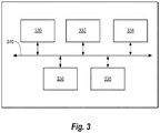
- FIG. 3 is a block diagram of an example printer.
- Printer comprises a processor 330, memory 332, input/output (I/O) module 334, print engine 336 and controller 338 all coupled together on bus 340.
- I/O input/output
- printer may also have a display, a user interface module, an input device, and the like, but these items are not shown for clarity.
- Processor 330 may comprise a central processing unit (CPU), a microprocessor, an application specific integrated circuit (ASIC), or a combination of these devices.
- Memory 332 may comprise volatile memory, non-volatile memory, and a storage device. Memory 332 is a non-transitory computer readable medium.
- non-volatile memory examples include, but are not limited to, electrically erasable programmable read only memory (EEPROM) and read only memory (ROM).
- volatile memory examples include, but are not limited to, static random access memory (SRAM), and dynamic random access memory (DRAM).
- SRAM static random access memory
- DRAM dynamic random access memory
- storage devices include, but are not limited to, hard disk drives, compact disc drives, digital versatile disc drives, optical drives, and flash memory devices.
- I/O module 334 is used to couple printer to other devices, for example the Internet or a computer.
- Print engine 336 may comprise a media supply system, a printhead, a drying assembly, an ink supply system, and the like.
- Printer has code, typically called firmware, stored in the memory 332.
- the firmware is stored as computer readable instructions in the non-transitory computer readable medium (i.e. the memory 332).
- Processor 330 generally retrieves and executes the instructions stored in the non-transitory computer-readable medium to operate the printer. In one example, processor executes code that directs controller 338 to control a drying assembly in the print engine 336.
- Figure 4 is an example block diagram of the processor 330 coupled to memory 332.
- Memory 332 contains firmware 442.
- Firmware 442 contains a drying module 444.
- the processor 330 executes the code in drying module 444 to direct controller 338 to control the drying assembly 108.
- Controller 338 is used to control the drying assembly 108. Drying assembly 108 heats the ink, media and any other components deposited on the media. The ink is heated to above a predetermined temperature threshold to ensure proper curing. The ink is also heated uniformly across the width of the media.
- two controllers may be used, one controller to control the fan speeds and thereby control the temperature uniformity across the page, and one controller to control the power to the heating elements thereby controlling the average temperature of the air leaving the drying assembly. In other examples one controller will be used to control both the fan speed and the heating elements. The single controller will still control the two systems independently.
- the controller adjusts the power to the heating elements and the speed of the fans to ensure that the ink reaches the threshold temperature evenly across the media.
- all of the N heating elements are coupled together and receive the same power setting.
- the controller adjusts the power setting to the N heating elements to control the average temperature of the air leaving the drying assembly 108.
- the controller can adjust the speed of each of the N fans 214 independently.
- the controller adjusts the fan speed of individual fans to maintain a uniform temperature across the width of the media while keeping the sum of the air flow through all the fans constant.
- One way to keep the total airflow constant is to keep the sum of the PWM from all of the fans at a constant value.
- FIG. 5 is a flow chart for an example method for controlling the fans in a drying assembly.
- the fan speed control method starts at step 550 where the startup parameters are set.
- the startup parameters include the initial fan speed control signal for each of the N fans.
- the startup parameters may include a delay time to allow the fans to get up to speed before entering the fan speed control loop.
- a temperature control method is also started. The temperature control method is used to keep the average temperature exiting the fans at a given value.
- Block 552 is the start of the fan speed control loop.
- the air temperature near the exhausts of each of the N tans is determined by reading the temperature sensors for each fan unit.
- the average air temperature is calculated as well as a delta temperature at each fan unit.
- the delta temperature for each fan unit is the average air temperature minus the air temperature at that fan unit.
- the delta air temperature for each fan unit is compared to a threshold value. When all of the delta temperatures are below the threshold value the temperature uniformity across the fan units is within a predetermined range. Therefore flow returns to block 552.
- a negative delta temperature for a fan unit means the air temperature at that fan unit is higher than the average air temperature.
- a positive delta temperature for a fan unit means the air temperature at that fan unit is lower than the average air temperature.
- the fan speeds for fans with air temperature higher than the average air temperature i.e. a negative delta temperature
- the fan speeds for fans with air temperature lower than the average air temperature are decreased.
- the sum of the airflow through all the fans is kept at a constant value.
- the fan speed control signal is typically a pulse width modulation (PWM) signal.
- PWM pulse width modulation
- equation 1 is used to determine the new fan speed control signal at block 558.
- PWM i t + ⁇ t PWM i t + K int ⁇ err _ int _ i t + ⁇ t
- PWM i (t+ ⁇ t) is the new fan speed control signal at time t plus delta time ( ⁇ t) for the i th fan unit
- PWM i (t) is the old fan speed control signal at time t for the i th fan unit
- K int is the gain for the interval delta time
- err_int_i(t+ ⁇ t) is the error signal for the i th fan unit for the interval delta time.
- Delta t ( ⁇ t) may be in the range between 0.1 second through 40 seconds, for example 1 second.
- K int is calculated using equation 2.
- K im 0.04 ⁇ % ⁇ PWM / C
- %PWM/C is the relationship between the %PWM signal and the temperature (Celsius).
- K int may be set in the range between 0.5 %PWM/C through 0.001 %PWM/C.
- err_int_i(t+ ⁇ t) is determined using equation 3.
- T i and T ave are the air temperature at the i th fan unit and the average air temperature respectively.
- Equation 1 a derivative term is added to equation 1 to improve the stability of the servo loop.
- the derivative takes into account the relative slope of the temperature (T i ) vs. time (t) curve at each fan unit compared to the average temperature (T ave ) vs. time (t) curve.
- Equation 1 becomes equation 4.
- PWM i t + ⁇ t PWM i t + K int ⁇ err _ int _ i t + ⁇ t + K d ⁇ err _ der _ i t + ⁇ t
- K d 0.6 %PWM/(C/sec)
- err_der_i(t+ ⁇ t) is defined in equation 5.
- ⁇ i and ⁇ ave are the slope of the temperature vs. time curve for the i th fan unit and the temperature vs. time curve for the average temperature, respectively.
- the thermal gain of the system is defined as the change in air temperature for a given change in the PWM percent (C/PWM%). In some examples the thermal gain is between 4 and 15 degrees C for a change of one percent in the PWM duty cycle, for example 6.67 C/PWM%. Because of this thermal gain, small changes in the fan speed control signal can cause large changes in air temperature. During operation a typical range for the fan speed control signal is between 40% - 90% PWM.
- the change in air speed/pressure for a given change in PWM% in the average fans speed control signal is dependent on the number of fan units, the fan type, the absolute PWM of the fan speed control signal and the fan outlet/exhaust geometry.
- an absolute fan speed control signal of 83% PWM in all 3 fans
- results in 2.3 m 3 /min or a 45.1 Pa (4.6 mmH 2 O) pressure
- at an absolute fan speed control signal of 73% PWM results in 2.0 m 3 /min (or a 37.2 Pa (3.8 mm H 2 O) pressure).
- a typical air speed at the fan exhaust is between 5 - 20 m/sec.
Landscapes
- Engineering & Computer Science (AREA)
- Mechanical Engineering (AREA)
- General Engineering & Computer Science (AREA)
- Ink Jet (AREA)
- Drying Of Solid Materials (AREA)
Claims (15)
- Trocknungsbaugruppe (108) für einen Drucker (100), die Folgendes umfasst:eine Anzahl N von Lüftereinheiten, die darauf gerichtet sind, Luft in eine Trocknungszone zu drücken, dadurch gekennzeichnet, dass N eine ganze Zahl 2 oder höher ist und jede Lüftereinheit Folgendes umfasst:einen Lüfter (214);ein Heizelement (216), das positioniert ist, um die vom Lüfter (214) bewegte Luft zu erwärmen; undeinen Temperatursensor (218), der in der Nähe eines Auslasses der Lüftereinheit positioniert ist;eine Steuerung (338), die mit jeder Lüftereinheit gekoppelt ist, wobei die Steuerung (338) den Temperatursensor (218) in jeder Lüftereinheit überwacht, wobei die Steuerung (338) eine Drehzahl jedes Lüfters (214) unabhängig einstellt, um die gleiche Temperatur bei allen N Lüftereinheiten aufrechtzuerhalten, wobei die Steuerung (338) den Gesamtluftstrom durch alle N Lüftereinheiten hindurch auf einem konstanten Wert hält.
- Trocknungsbaugruppe (108) nach Anspruch 1, wobei alle Heizelemente (216) in allen N Lüftereinheiten miteinander gekoppelt sind und mit einem einzigen Heizelementsteuersignal gesteuert werden.
- Trocknungsbaugruppe (108) nach Anspruch 1, wobei die Drehzahl jedes Lüfters (214) unter Verwendung eines Lüfterdrehzahlsteuersignals unabhängig einstellbar ist, wobei jedes Lüfterdrehzahlsteuersignal ein Pulsweitenmodulationsignal (PWM-Signal) ist und wobei ein eingestelltes Lüfterdrehzahlsteuersignal für jeden Lüfter (214) gleich
PWMN(t) + Kint ∗ err_int_N(t + Δt) ist, wobei PWMN(t) ein Lüfterdrehzahlsteuersignal zu einem Zeitpunkt t für die N-te Lüftereinheit ist, Kint eine Verstärkung für die Intervall-Delta-Zeit (Δt) ist und err_int_N(t + Δt) ein Fehlersignal für die N-te Lüftereinheit für die Intervall-Delta-Zeit (Δt) ist. - Trocknungsbaugruppe (108) nach Anspruch 4, wobei das eingestellte Lüfterdrehzahlsteuersignal für jeden Lüfter (214) den Term Kd ∗ err_der_N(t + Δt) beinhaltet, wobei Kd eine Verstärkung ist und err_der_N(t + Δt) ein Fehlersignal für die N-te Einheit des Lüfters(214) für die Intervall-Delta-Zeit (Δt) ist, das auf einer relativen Steigung der Vergleichskurve von Temperatur (TN) und Zeit (t) für die N-te Lüftereinheit im gegenüber einer Vergleichskurve von Durchschnittstemperatur (Tave) und Zeit (t) basiert.
- Trocknungsbaugruppe (108) nach Anspruch 4, wobei die Delta-Zeit (Δt) im Bereich von 0,1 Sekunde bis 40 Sekunden liegt.
- Trocknungsbaugruppe (108) nach Anspruch 1, die ferner Folgendes umfasst:dass die Steuerung (338) eine Durchschnittstemperatur für alle Lüfter (214) bestimmt;dass die Steuerung (338) eine Delta-Temperatur für jeden Lüfter (214) bestimmt, wobei die Delta-Temperatur gleich der Durchschnittstemperatur minus einer Temperatur an jedem Lüfter (214) ist;dass die Steuerung (338) die gleiche Lüfterdrehzahl für jeden der Lüfter (214) aufrechterhält, wenn die Delta-Temperatur für alle Lüfter (214) unter einem Schwellenwert liegt.
- Trocknungsbaugruppe (108) nach Anspruch 1, wobei N im Bereich von 3 bis 8 liegt.
- Trocknungsbaugruppe (108) nach Anspruch 1, die ferner Folgendes umfasst:
einen Träger (220), wobei die Lüftereinheiten entlang des Trägers (220) um einen Abstand X beabstandet sind, wobei der Abstand X im Bereich von 30 mm bis 800 mm liegt. - Verfahren zum Steuern einer Trocknungsbaugruppe (108) eines Druckers (100), das Folgendes umfasst:Bestimmen der Temperatur von Luft, die aus jeder der N Lüftereinheiten austritt,dadurch gekennzeichnet, dass N eine ganze Zahl größer als eins ist;Berechnen einer durchschnittlichen Lufttemperatur für alle N Lüfter (214);Verringern einer Lüfterdrehzahl für jeden Lüfter (214) mit einer Lufttemperatur, die niedriger als die durchschnittliche Lufttemperatur ist;Erhöhen der Lüfterdrehzahl für jeden Lüfter (214) mit einer Lufttemperatur, die höher als die durchschnittliche Lufttemperatur ist;Halten einer Summe des Luftstroms durch alle N Lüfter (214) auf einem konstanten Wert.
- Verfahren nach Anspruch 10, das ferner Folgendes umfasst:
Einstellen eines Heizelements (216) in jeder der N Lüftereinheiten unter Verwendung eines einzelnen Servosteuersignals. - Verfahren nach Anspruch 10, das ferner ein Erhöhen oder Verringern der Lüfterdrehzahl für jeden Lüfter (214) einmal pro Sekunde umfasst.
- Verfahren nach Anspruch 10, wobei 3 oder 4 Lüftereinheiten vorhanden sind.
- Verfahren nach Anspruch 10, wobei die Lüfterdrehzahl unter Verwendung eines Pulsweitenmodulationsignals (PWM-Signal) gesteuert wird und wobei ein eingestelltes Lüfterdrehzahlsteuersignal für jeden Lüfter (214) gleich PWMN(t) + Kint ∗ err_int_N(t + Δt) ist, wobei PWMN(t) ein Lüfterdrehzahlsteuersignal zu einem Zeitpunkt t für die N-te Lüftereinheit ist, Kint eine Verstärkung für die Intervall-Delta-Zeit (Δt) ist und err_int_N(t + Δt) ein Fehlersignal für die N-te Lüftereinheit für die Intervall-Delta-Zeit (Δt) ist.
- Verfahren nach Anspruch 13, wobei das eingestellte Lüfterdrehzahlsteuersignal für jeden Lüfter (214) den Term Kd ∗ err_der_N(t + Δt) beinhaltet, wobei Kd eine Verstärkung ist und err_der_N(t + Δt) ein Fehlersignal für die N-te Lüftereinheit für die Intervall-Delta-Zeit (Δt) ist, das auf einer relativen Steigung der Vergleichskurve von Temperatur (TN) und Zeit (t) für die N-te Lüftereinheit gegenüber einer Vergleichskurve von Durchschnittstemperatur (Tave) und Zeit (t) basiert.
- Verfahren nach Anspruch 13, wobei die Summe aller PWM-Steuersignale für jeden Lüfter (214) auf einem vorbestimmten Wert gehalten wird.
Applications Claiming Priority (1)
| Application Number | Priority Date | Filing Date | Title |
|---|---|---|---|
| PCT/US2012/056450 WO2014046665A1 (en) | 2012-09-21 | 2012-09-21 | Drying assembly |
Publications (3)
| Publication Number | Publication Date |
|---|---|
| EP2897809A1 EP2897809A1 (de) | 2015-07-29 |
| EP2897809A4 EP2897809A4 (de) | 2016-06-22 |
| EP2897809B1 true EP2897809B1 (de) | 2020-05-13 |
Family
ID=50341801
Family Applications (1)
| Application Number | Title | Priority Date | Filing Date |
|---|---|---|---|
| EP12885138.3A Active EP2897809B1 (de) | 2012-09-21 | 2012-09-21 | Trocknungsanordnung für einen drucker und steuerungsverfahren für eine trocknungsanordnung für einen drucker. |
Country Status (4)
| Country | Link |
|---|---|
| US (3) | US9283772B2 (de) |
| EP (1) | EP2897809B1 (de) |
| CN (1) | CN104487258B (de) |
| WO (1) | WO2014046665A1 (de) |
Families Citing this family (19)
| Publication number | Priority date | Publication date | Assignee | Title |
|---|---|---|---|---|
| US8629539B2 (en) | 2012-01-16 | 2014-01-14 | Allegro Microsystems, Llc | Methods and apparatus for magnetic sensor having non-conductive die paddle |
| EP2897809B1 (de) | 2012-09-21 | 2020-05-13 | Hewlett-Packard Development Company, L.P. | Trocknungsanordnung für einen drucker und steuerungsverfahren für eine trocknungsanordnung für einen drucker. |
| JP6167774B2 (ja) * | 2013-09-06 | 2017-07-26 | セイコーエプソン株式会社 | 記録装置 |
| WO2015185141A1 (en) * | 2014-06-05 | 2015-12-10 | Hewlett-Packard Development Company L.P. | Apparatus to provide heated gas to printed media |
| JP6471846B2 (ja) * | 2014-06-19 | 2019-02-20 | 株式会社リコー | 画像形成装置 |
| DE102015104382A1 (de) | 2015-03-24 | 2016-09-29 | Manroland Web Systems Gmbh | Verfahren zur geregelten und gesteuerten Wiederbefeuchtung und Trocknung von Papierbahnen |
| WO2018048403A1 (en) * | 2016-09-08 | 2018-03-15 | Hewlett-Packard Development Company, L.P. | Printer dryer monitor |
| JP6930096B2 (ja) * | 2016-12-07 | 2021-09-01 | セイコーエプソン株式会社 | 印刷装置 |
| US10308010B2 (en) | 2017-02-08 | 2019-06-04 | Ricoh Company, Ltd. | Infrared-heated air knives for dryers |
| CN107121993B (zh) * | 2017-04-26 | 2019-01-25 | 上海富士施乐有限公司 | 一种控制复印机的风扇开关的方法 |
| EP3615337B1 (de) * | 2017-04-27 | 2022-01-05 | Hewlett-Packard Development Company, L.P. | Sequenzierung von lasten unter verwendung von temperatur |
| US11166482B2 (en) * | 2018-09-18 | 2021-11-09 | Packline Technologies, Inc. | Modular produce drying tunnel and methods of use |
| JP7110941B2 (ja) * | 2018-11-26 | 2022-08-02 | セイコーエプソン株式会社 | 媒体加熱装置及び印刷装置 |
| CN109501449A (zh) * | 2018-12-07 | 2019-03-22 | 安徽瀚洋纸品印刷有限公司 | 一种印刷机用热风循环干燥系统 |
| WO2020131040A1 (en) * | 2018-12-18 | 2020-06-25 | Hewlett-Packard Development Company, L.P. | Pulse width modulation driven heating sources |
| US10991644B2 (en) | 2019-08-22 | 2021-04-27 | Allegro Microsystems, Llc | Integrated circuit package having a low profile |
| US11969991B2 (en) | 2020-01-29 | 2024-04-30 | Hewlett-Packard Development Company, L.P. | Directional drying |
| JP7521321B2 (ja) * | 2020-08-19 | 2024-07-24 | セイコーエプソン株式会社 | 記録装置及び記録媒体の乾燥方法 |
| CN116899250B (zh) * | 2023-08-04 | 2025-09-09 | 普林斯(安庆)医药科技有限公司 | 一种氯代烷烃氯化混合蒸馏处理设备及工艺方法 |
Family Cites Families (11)
| Publication number | Priority date | Publication date | Assignee | Title |
|---|---|---|---|---|
| US5406316A (en) | 1992-05-01 | 1995-04-11 | Hewlett-Packard Company | Airflow system for ink-jet printer |
| US6463674B1 (en) | 2000-11-27 | 2002-10-15 | Xerox Corporation | Hot air impingement drying system for inkjet images |
| US6854842B2 (en) * | 2002-12-09 | 2005-02-15 | Xerox Corporation | Ink jet printer having a dual function air cooling and drying system |
| US7101031B2 (en) | 2003-10-25 | 2006-09-05 | Hewlett-Packard Development Company, L.P. | Property of air determination within image-forming device |
| US7317467B2 (en) * | 2004-10-19 | 2008-01-08 | Lexmark International, Inc. | System for controlling printer cooling fan |
| JP2006187920A (ja) | 2005-01-05 | 2006-07-20 | Fuji Photo Film Co Ltd | 感熱プリンタ |
| DE102009021004B4 (de) | 2009-04-24 | 2026-04-02 | Dürr Systems Ag | Trocknungs- und/oder Härtungsanlage |
| JP2011056699A (ja) | 2009-09-08 | 2011-03-24 | Seiko Epson Corp | 印刷装置、及び印刷装置の制御方法 |
| US8596777B2 (en) * | 2010-04-30 | 2013-12-03 | Seiko Epson Corporation | Liquid ejecting apparatus |
| JP5357138B2 (ja) | 2010-12-27 | 2013-12-04 | 富士フイルム株式会社 | 画像形成装置 |
| EP2897809B1 (de) | 2012-09-21 | 2020-05-13 | Hewlett-Packard Development Company, L.P. | Trocknungsanordnung für einen drucker und steuerungsverfahren für eine trocknungsanordnung für einen drucker. |
-
2012
- 2012-09-21 EP EP12885138.3A patent/EP2897809B1/de active Active
- 2012-09-21 WO PCT/US2012/056450 patent/WO2014046665A1/en not_active Ceased
- 2012-09-21 CN CN201280075063.2A patent/CN104487258B/zh active Active
- 2012-09-21 US US14/414,866 patent/US9283772B2/en active Active
-
2016
- 2016-02-17 US US15/046,383 patent/US9809022B2/en active Active
-
2017
- 2017-07-25 US US15/659,025 patent/US10076903B2/en active Active
Non-Patent Citations (1)
| Title |
|---|
| None * |
Also Published As
| Publication number | Publication date |
|---|---|
| EP2897809A4 (de) | 2016-06-22 |
| US20150202896A1 (en) | 2015-07-23 |
| CN104487258A (zh) | 2015-04-01 |
| WO2014046665A1 (en) | 2014-03-27 |
| US20170320323A1 (en) | 2017-11-09 |
| US9283772B2 (en) | 2016-03-15 |
| US9809022B2 (en) | 2017-11-07 |
| CN104487258B (zh) | 2017-03-08 |
| EP2897809A1 (de) | 2015-07-29 |
| US10076903B2 (en) | 2018-09-18 |
| US20160159090A1 (en) | 2016-06-09 |
Similar Documents
| Publication | Publication Date | Title |
|---|---|---|
| EP2897809B1 (de) | Trocknungsanordnung für einen drucker und steuerungsverfahren für eine trocknungsanordnung für einen drucker. | |
| CN105579232B (zh) | 应用于干燥印刷流体的热能 | |
| US9475285B2 (en) | Liquid ejecting apparatus | |
| US8939572B2 (en) | Control of air-based media dryer | |
| US11325400B2 (en) | Control of a heated system temperature | |
| EP3230071B1 (de) | Trockner mit einem strömungsventil | |
| US8646893B2 (en) | System and method for improving temperature uniformity of image drums | |
| US7101031B2 (en) | Property of air determination within image-forming device | |
| US20200079122A1 (en) | Method and system for reducing the undulation of a recording medium | |
| JP7781027B2 (ja) | 印刷方法および印刷装置 | |
| JP7771000B2 (ja) | 印刷装置および印刷方法 | |
| JP2006246670A (ja) | プリンタおよびプリンタ用モータの制御方法 | |
| US8287078B2 (en) | Inkjet printing system having environmentally responsive thermal control mode | |
| US20240316946A1 (en) | Inkjet printing apparatus | |
| KR100530231B1 (ko) | 히터편차 보상이 가능한 잉크젯 프린터 및 그에 의한히터편차 보상방법 | |
| JP2026046628A (ja) | 記録装置、及び記録装置の制御方法 | |
| WO2020131023A1 (en) | Pulse width modulation value calculations | |
| WO2020131040A1 (en) | Pulse width modulation driven heating sources | |
| JP2021123025A (ja) | 液体を吐出する装置 | |
| JP2000280455A (ja) | インクジェット記録装置及びインクジェット記録装置におけるヘッド温度補正方法 | |
| JP2008126623A (ja) | ヘッド温度制御手段を有するインクジェット記録装置 | |
| JP2016137606A (ja) | 液体噴射装置 |
Legal Events
| Date | Code | Title | Description |
|---|---|---|---|
| PUAI | Public reference made under article 153(3) epc to a published international application that has entered the european phase |
Free format text: ORIGINAL CODE: 0009012 |
|
| 17P | Request for examination filed |
Effective date: 20150114 |
|
| AK | Designated contracting states |
Kind code of ref document: A1 Designated state(s): AL AT BE BG CH CY CZ DE DK EE ES FI FR GB GR HR HU IE IS IT LI LT LU LV MC MK MT NL NO PL PT RO RS SE SI SK SM TR |
|
| AX | Request for extension of the european patent |
Extension state: BA ME |
|
| DAX | Request for extension of the european patent (deleted) | ||
| RA4 | Supplementary search report drawn up and despatched (corrected) |
Effective date: 20160524 |
|
| RIC1 | Information provided on ipc code assigned before grant |
Ipc: B41F 23/04 20060101ALI20160518BHEP Ipc: F26B 21/10 20060101ALI20160518BHEP Ipc: B41J 11/00 20060101ALI20160518BHEP Ipc: B41J 29/377 20060101AFI20160518BHEP Ipc: F26B 21/00 20060101ALI20160518BHEP |
|
| RAP1 | Party data changed (applicant data changed or rights of an application transferred) |
Owner name: HEWLETT-PACKARD DEVELOPMENT COMPANY, L.P. |
|
| GRAP | Despatch of communication of intention to grant a patent |
Free format text: ORIGINAL CODE: EPIDOSNIGR1 |
|
| STAA | Information on the status of an ep patent application or granted ep patent |
Free format text: STATUS: GRANT OF PATENT IS INTENDED |
|
| INTG | Intention to grant announced |
Effective date: 20200203 |
|
| GRAS | Grant fee paid |
Free format text: ORIGINAL CODE: EPIDOSNIGR3 |
|
| GRAA | (expected) grant |
Free format text: ORIGINAL CODE: 0009210 |
|
| STAA | Information on the status of an ep patent application or granted ep patent |
Free format text: STATUS: THE PATENT HAS BEEN GRANTED |
|
| AK | Designated contracting states |
Kind code of ref document: B1 Designated state(s): AL AT BE BG CH CY CZ DE DK EE ES FI FR GB GR HR HU IE IS IT LI LT LU LV MC MK MT NL NO PL PT RO RS SE SI SK SM TR |
|
| REG | Reference to a national code |
Ref country code: GB Ref legal event code: FG4D |
|
| REG | Reference to a national code |
Ref country code: CH Ref legal event code: EP |
|
| REG | Reference to a national code |
Ref country code: DE Ref legal event code: R096 Ref document number: 602012070141 Country of ref document: DE |
|
| REG | Reference to a national code |
Ref country code: AT Ref legal event code: REF Ref document number: 1269752 Country of ref document: AT Kind code of ref document: T Effective date: 20200615 |
|
| REG | Reference to a national code |
Ref country code: NL Ref legal event code: FP |
|
| REG | Reference to a national code |
Ref country code: LT Ref legal event code: MG4D |
|
| PG25 | Lapsed in a contracting state [announced via postgrant information from national office to epo] |
Ref country code: FI Free format text: LAPSE BECAUSE OF FAILURE TO SUBMIT A TRANSLATION OF THE DESCRIPTION OR TO PAY THE FEE WITHIN THE PRESCRIBED TIME-LIMIT Effective date: 20200513 Ref country code: NO Free format text: LAPSE BECAUSE OF FAILURE TO SUBMIT A TRANSLATION OF THE DESCRIPTION OR TO PAY THE FEE WITHIN THE PRESCRIBED TIME-LIMIT Effective date: 20200813 Ref country code: GR Free format text: LAPSE BECAUSE OF FAILURE TO SUBMIT A TRANSLATION OF THE DESCRIPTION OR TO PAY THE FEE WITHIN THE PRESCRIBED TIME-LIMIT Effective date: 20200814 Ref country code: SE Free format text: LAPSE BECAUSE OF FAILURE TO SUBMIT A TRANSLATION OF THE DESCRIPTION OR TO PAY THE FEE WITHIN THE PRESCRIBED TIME-LIMIT Effective date: 20200513 Ref country code: LT Free format text: LAPSE BECAUSE OF FAILURE TO SUBMIT A TRANSLATION OF THE DESCRIPTION OR TO PAY THE FEE WITHIN THE PRESCRIBED TIME-LIMIT Effective date: 20200513 Ref country code: PT Free format text: LAPSE BECAUSE OF FAILURE TO SUBMIT A TRANSLATION OF THE DESCRIPTION OR TO PAY THE FEE WITHIN THE PRESCRIBED TIME-LIMIT Effective date: 20200914 Ref country code: IS Free format text: LAPSE BECAUSE OF FAILURE TO SUBMIT A TRANSLATION OF THE DESCRIPTION OR TO PAY THE FEE WITHIN THE PRESCRIBED TIME-LIMIT Effective date: 20200913 |
|
| PG25 | Lapsed in a contracting state [announced via postgrant information from national office to epo] |
Ref country code: RS Free format text: LAPSE BECAUSE OF FAILURE TO SUBMIT A TRANSLATION OF THE DESCRIPTION OR TO PAY THE FEE WITHIN THE PRESCRIBED TIME-LIMIT Effective date: 20200513 Ref country code: BG Free format text: LAPSE BECAUSE OF FAILURE TO SUBMIT A TRANSLATION OF THE DESCRIPTION OR TO PAY THE FEE WITHIN THE PRESCRIBED TIME-LIMIT Effective date: 20200813 Ref country code: HR Free format text: LAPSE BECAUSE OF FAILURE TO SUBMIT A TRANSLATION OF THE DESCRIPTION OR TO PAY THE FEE WITHIN THE PRESCRIBED TIME-LIMIT Effective date: 20200513 Ref country code: LV Free format text: LAPSE BECAUSE OF FAILURE TO SUBMIT A TRANSLATION OF THE DESCRIPTION OR TO PAY THE FEE WITHIN THE PRESCRIBED TIME-LIMIT Effective date: 20200513 |
|
| REG | Reference to a national code |
Ref country code: AT Ref legal event code: MK05 Ref document number: 1269752 Country of ref document: AT Kind code of ref document: T Effective date: 20200513 |
|
| PG25 | Lapsed in a contracting state [announced via postgrant information from national office to epo] |
Ref country code: AL Free format text: LAPSE BECAUSE OF FAILURE TO SUBMIT A TRANSLATION OF THE DESCRIPTION OR TO PAY THE FEE WITHIN THE PRESCRIBED TIME-LIMIT Effective date: 20200513 |
|
| PG25 | Lapsed in a contracting state [announced via postgrant information from national office to epo] |
Ref country code: DK Free format text: LAPSE BECAUSE OF FAILURE TO SUBMIT A TRANSLATION OF THE DESCRIPTION OR TO PAY THE FEE WITHIN THE PRESCRIBED TIME-LIMIT Effective date: 20200513 Ref country code: IT Free format text: LAPSE BECAUSE OF FAILURE TO SUBMIT A TRANSLATION OF THE DESCRIPTION OR TO PAY THE FEE WITHIN THE PRESCRIBED TIME-LIMIT Effective date: 20200513 Ref country code: RO Free format text: LAPSE BECAUSE OF FAILURE TO SUBMIT A TRANSLATION OF THE DESCRIPTION OR TO PAY THE FEE WITHIN THE PRESCRIBED TIME-LIMIT Effective date: 20200513 Ref country code: CZ Free format text: LAPSE BECAUSE OF FAILURE TO SUBMIT A TRANSLATION OF THE DESCRIPTION OR TO PAY THE FEE WITHIN THE PRESCRIBED TIME-LIMIT Effective date: 20200513 Ref country code: ES Free format text: LAPSE BECAUSE OF FAILURE TO SUBMIT A TRANSLATION OF THE DESCRIPTION OR TO PAY THE FEE WITHIN THE PRESCRIBED TIME-LIMIT Effective date: 20200513 Ref country code: SM Free format text: LAPSE BECAUSE OF FAILURE TO SUBMIT A TRANSLATION OF THE DESCRIPTION OR TO PAY THE FEE WITHIN THE PRESCRIBED TIME-LIMIT Effective date: 20200513 Ref country code: AT Free format text: LAPSE BECAUSE OF FAILURE TO SUBMIT A TRANSLATION OF THE DESCRIPTION OR TO PAY THE FEE WITHIN THE PRESCRIBED TIME-LIMIT Effective date: 20200513 Ref country code: EE Free format text: LAPSE BECAUSE OF FAILURE TO SUBMIT A TRANSLATION OF THE DESCRIPTION OR TO PAY THE FEE WITHIN THE PRESCRIBED TIME-LIMIT Effective date: 20200513 |
|
| REG | Reference to a national code |
Ref country code: DE Ref legal event code: R097 Ref document number: 602012070141 Country of ref document: DE |
|
| PG25 | Lapsed in a contracting state [announced via postgrant information from national office to epo] |
Ref country code: PL Free format text: LAPSE BECAUSE OF FAILURE TO SUBMIT A TRANSLATION OF THE DESCRIPTION OR TO PAY THE FEE WITHIN THE PRESCRIBED TIME-LIMIT Effective date: 20200513 Ref country code: SK Free format text: LAPSE BECAUSE OF FAILURE TO SUBMIT A TRANSLATION OF THE DESCRIPTION OR TO PAY THE FEE WITHIN THE PRESCRIBED TIME-LIMIT Effective date: 20200513 |
|
| PLBE | No opposition filed within time limit |
Free format text: ORIGINAL CODE: 0009261 |
|
| STAA | Information on the status of an ep patent application or granted ep patent |
Free format text: STATUS: NO OPPOSITION FILED WITHIN TIME LIMIT |
|
| 26N | No opposition filed |
Effective date: 20210216 |
|
| PG25 | Lapsed in a contracting state [announced via postgrant information from national office to epo] |
Ref country code: MC Free format text: LAPSE BECAUSE OF FAILURE TO SUBMIT A TRANSLATION OF THE DESCRIPTION OR TO PAY THE FEE WITHIN THE PRESCRIBED TIME-LIMIT Effective date: 20200513 |
|
| REG | Reference to a national code |
Ref country code: CH Ref legal event code: PL |
|
| PG25 | Lapsed in a contracting state [announced via postgrant information from national office to epo] |
Ref country code: SI Free format text: LAPSE BECAUSE OF FAILURE TO SUBMIT A TRANSLATION OF THE DESCRIPTION OR TO PAY THE FEE WITHIN THE PRESCRIBED TIME-LIMIT Effective date: 20200513 |
|
| REG | Reference to a national code |
Ref country code: BE Ref legal event code: MM Effective date: 20200930 |
|
| PG25 | Lapsed in a contracting state [announced via postgrant information from national office to epo] |
Ref country code: LU Free format text: LAPSE BECAUSE OF NON-PAYMENT OF DUE FEES Effective date: 20200921 |
|
| PG25 | Lapsed in a contracting state [announced via postgrant information from national office to epo] |
Ref country code: LI Free format text: LAPSE BECAUSE OF NON-PAYMENT OF DUE FEES Effective date: 20200930 Ref country code: IE Free format text: LAPSE BECAUSE OF NON-PAYMENT OF DUE FEES Effective date: 20200921 Ref country code: CH Free format text: LAPSE BECAUSE OF NON-PAYMENT OF DUE FEES Effective date: 20200930 Ref country code: BE Free format text: LAPSE BECAUSE OF NON-PAYMENT OF DUE FEES Effective date: 20200930 |
|
| PG25 | Lapsed in a contracting state [announced via postgrant information from national office to epo] |
Ref country code: TR Free format text: LAPSE BECAUSE OF FAILURE TO SUBMIT A TRANSLATION OF THE DESCRIPTION OR TO PAY THE FEE WITHIN THE PRESCRIBED TIME-LIMIT Effective date: 20200513 Ref country code: MT Free format text: LAPSE BECAUSE OF FAILURE TO SUBMIT A TRANSLATION OF THE DESCRIPTION OR TO PAY THE FEE WITHIN THE PRESCRIBED TIME-LIMIT Effective date: 20200513 Ref country code: CY Free format text: LAPSE BECAUSE OF FAILURE TO SUBMIT A TRANSLATION OF THE DESCRIPTION OR TO PAY THE FEE WITHIN THE PRESCRIBED TIME-LIMIT Effective date: 20200513 |
|
| PG25 | Lapsed in a contracting state [announced via postgrant information from national office to epo] |
Ref country code: MK Free format text: LAPSE BECAUSE OF FAILURE TO SUBMIT A TRANSLATION OF THE DESCRIPTION OR TO PAY THE FEE WITHIN THE PRESCRIBED TIME-LIMIT Effective date: 20200513 |
|
| PGFP | Annual fee paid to national office [announced via postgrant information from national office to epo] |
Ref country code: NL Payment date: 20230822 Year of fee payment: 12 |
|
| PGFP | Annual fee paid to national office [announced via postgrant information from national office to epo] |
Ref country code: GB Payment date: 20230823 Year of fee payment: 12 |
|
| PGFP | Annual fee paid to national office [announced via postgrant information from national office to epo] |
Ref country code: FR Payment date: 20230822 Year of fee payment: 12 |
|
| REG | Reference to a national code |
Ref country code: NL Ref legal event code: MM Effective date: 20241001 |
|
| GBPC | Gb: european patent ceased through non-payment of renewal fee |
Effective date: 20240921 |
|
| PG25 | Lapsed in a contracting state [announced via postgrant information from national office to epo] |
Ref country code: NL Free format text: LAPSE BECAUSE OF NON-PAYMENT OF DUE FEES Effective date: 20241001 |
|
| PG25 | Lapsed in a contracting state [announced via postgrant information from national office to epo] |
Ref country code: GB Free format text: LAPSE BECAUSE OF NON-PAYMENT OF DUE FEES Effective date: 20240921 |
|
| PG25 | Lapsed in a contracting state [announced via postgrant information from national office to epo] |
Ref country code: FR Free format text: LAPSE BECAUSE OF NON-PAYMENT OF DUE FEES Effective date: 20240930 |
|
| REG | Reference to a national code |
Ref country code: DE Ref legal event code: R082 Ref document number: 602012070141 Country of ref document: DE Representative=s name: NOVAGRAAF BREVETS, FR |
|
| PGFP | Annual fee paid to national office [announced via postgrant information from national office to epo] |
Ref country code: DE Payment date: 20250820 Year of fee payment: 14 |