EP2898967B2 - Support d'outil de coupe, procédé de fabrication et utilisation d'un dispositif de fabrication génératif pour la fabrication d'un support d'outil de coupe - Google Patents
Support d'outil de coupe, procédé de fabrication et utilisation d'un dispositif de fabrication génératif pour la fabrication d'un support d'outil de coupe Download PDFInfo
- Publication number
- EP2898967B2 EP2898967B2 EP14000278.3A EP14000278A EP2898967B2 EP 2898967 B2 EP2898967 B2 EP 2898967B2 EP 14000278 A EP14000278 A EP 14000278A EP 2898967 B2 EP2898967 B2 EP 2898967B2
- Authority
- EP
- European Patent Office
- Prior art keywords
- cooling lubricant
- cutting tool
- holder
- holder body
- lubricant channel
- Prior art date
- Legal status (The legal status is an assumption and is not a legal conclusion. Google has not performed a legal analysis and makes no representation as to the accuracy of the status listed.)
- Active
Links
Images
Classifications
-
- B—PERFORMING OPERATIONS; TRANSPORTING
- B23—MACHINE TOOLS; METAL-WORKING NOT OTHERWISE PROVIDED FOR
- B23B—TURNING; BORING
- B23B27/00—Tools for turning or boring machines; Tools of a similar kind in general; Accessories therefor
- B23B27/04—Cutting-off tools
-
- B—PERFORMING OPERATIONS; TRANSPORTING
- B23—MACHINE TOOLS; METAL-WORKING NOT OTHERWISE PROVIDED FOR
- B23B—TURNING; BORING
- B23B27/00—Tools for turning or boring machines; Tools of a similar kind in general; Accessories therefor
- B23B27/10—Cutting tools with special provision for cooling
-
- B—PERFORMING OPERATIONS; TRANSPORTING
- B23—MACHINE TOOLS; METAL-WORKING NOT OTHERWISE PROVIDED FOR
- B23B—TURNING; BORING
- B23B29/00—Holders for non-rotary cutting tools; Boring bars or boring heads; Accessories for tool holders
- B23B29/04—Tool holders for a single cutting tool
- B23B29/043—Tool holders for a single cutting tool with cutting-off, grooving or profile cutting tools, i.e. blade- or disc-like main cutting parts
-
- B—PERFORMING OPERATIONS; TRANSPORTING
- B23—MACHINE TOOLS; METAL-WORKING NOT OTHERWISE PROVIDED FOR
- B23B—TURNING; BORING
- B23B2205/00—Fixation of cutting inserts in holders
- B23B2205/02—Fixation using an elastically deformable clamping member
-
- B—PERFORMING OPERATIONS; TRANSPORTING
- B23—MACHINE TOOLS; METAL-WORKING NOT OTHERWISE PROVIDED FOR
- B23B—TURNING; BORING
- B23B2250/00—Compensating adverse effects during turning, boring or drilling
- B23B2250/12—Cooling and lubrication
Definitions
- the following invention relates to a parting holder and to a manufacturing method for the parting holder.
- cooling lubricants for this purpose, which are fed to the cutting tool.
- the cooling lubricants mainly consist of water and contain certain additives, e.g. for lubrication, changing the wetting properties and / or anti-foaming agents.
- Early systems worked with large volume flows and a locally comparatively undefined cooling lubricant application, for example via flexible hoses that were brought up to the cutting tool.
- this type of cooling has the disadvantage that the cooling lubricant consumption is very high and the cooling is not very effective, since the place where the heat is generated, namely the cutting edge itself, is only insufficiently supplied with cooling lubricant; Chips flying off and / or deposited on the cutting tool can deflect the cooling lubricant jet and thus impair the cooling of the cutting edge. When grooving narrow grooves or parting off, it can even happen that the cooling lubricant supply to the cutting edge almost comes to a standstill.
- Cutting tool holders have therefore been developed which allow cooling lubricant to be conveyed directly to the cutting tool under high pressure.
- Such a cutting tool is from the DE 20 2012 004 900 U1 known.
- the cutting tool holder has a cooling lubricant channel that enables cooling lubricant to be fed directly to the cutting tool seat.
- the cutting insert or the cutting plate has a groove-like depression on its surface through which the cooling lubricant can be conveyed from an inner channel, which is formed by a simple hole in the holder body, to the cutting edge, whereby the chips can be washed away and washed away.
- Cutting tool holders have therefore been developed in which the coolant is only released shortly before the cutting insert.
- a parting sword from the WO 2013 132480 A1 known, in which there is a fluid supply bore on a side surface, which is connected to an outlet opening directly next to the cutting insert via a capillary bore which extends along the longitudinal axis of the sword.
- the fluid supply bore is closed on one side with a plug, while the other side is connected to a cooling lubricant supply on the machine tool side.
- the fluid supply channel is formed there by two fluidically connected bores which are at an angle to one another, which leads to flow losses.
- a parting blade made by Sandvik Coromant is known under the name Coroturn ® QD (see Product catalog "New tools and solutions", page 21, 2014 ), which has two outlet openings for cooling lubricant in the area of the cutting insert, which are present on the face of the parting blade; one outlet is above and the other below the cutting insert.
- one channel each extends from a central feed opening to the outlet openings, the channels being formed by bores in the sword body.
- a parting holder is off US 2010/0178116 A1 known.
- the present invention is based on the object of creating an improved cutting tool holder which allows improved local cooling of the cutting tool and improved chip removal.
- the parting holder has a holder body which has a cutting tool seat.
- the parting holder also has a clamping section for clamping the parting holder in a machine tool.
- the holder body there is at least one cooling lubricant channel which, according to the invention, advantageously has at least one outlet opening on a side surface of the holder body, where the latter emerges obliquely from the side surface.
- the outlet opening is aligned in such a way that a cooling lubricant jet that comes out of this cooling lubricant channel can be directed onto a surface of a cutting tool that lies in the cutting tool seat.
- Cutting tool here means an exchangeable cutting insert, in particular an indexable insert, which can consist of hard metal, diamond or ceramic, for example.
- Indexable insert which can consist of hard metal, diamond or ceramic, for example.
- Inclined means that the coolant channel does not emerge normal to the surface.
- the outlet opening present on the side surface of the holder body is provided for the purpose of directing a jet of cooling lubricant from the side onto the To straighten the cutting tool body, which both helps to improve chip evacuation and to keep the cutting tool body itself cooler, which also counteracts the thermal expansion of the parting holder.
- the parting holder according to the invention can form a parting sword, which has a very flat, plate-shaped holder body and is particularly suitable for large parting diameters, or a parting holder for small diameters, wherein the holder body can be connected, for example, to an elongated tool shaft in order to couple it to the machine tool .
- machine tool are meant here primarily lathes or automatic lathes; however, the tool holder can also be used in multi-axis machining centers.
- the parting holder can be screwed to a tool holder of the machine tool, it being possible for through-holes for clamping screws to be provided; alternatively, it can also be clamped in a clamp holder, so that the parting holder according to the invention is more or less received by a higher-level holder, the higher-level holder being able to be coupled to the tool holder of the machine tool, for example, via a form-fitting quick fastening system.
- the parting holder according to the invention has more than one lateral outlet opening for cooling lubricant; there are outlet bores provided on side surfaces of the parting holder facing away from one another, which apply cooling lubricant onto the cutting tool from opposite directions.
- the direction is largely determined by the alignment of the channel axis.
- an angle-adjustable nozzle is inserted into the outlet bore, which nozzle allows the direction of application to be changed.
- the holder body can have one or more supply opening (s) for cooling lubricant, which is / are preferably present in the clamping section, wherein the supply opening (s) can be fluidically connected to the cooling lubricant source.
- the cooling lubricant channel extends from the supply opening to the outlet opening. Via the feed opening it is possible to couple the cutting tool holder according to the invention to a cooling lubricant supply system of the machine tool; this can in particular take place at the same time as the mechanical coupling.
- the cooling lubricant channel does not have to extend along the shortest connection between the supply opening and the outlet opening, but its course can also be adapted with regard to a certain minimum rigidity to be achieved.
- a channel that is not straight can also be necessary if bores or the like "block" the direct path; the cooling lubricant channel can also have one or more deflections, which can advantageously be rounded. By rounding the deflections, a lower pressure loss is achieved, which contributes to an energy-saving mode of operation.
- the parting holder can have one or more upper cooling lubricant channels which each open into an upper outlet opening.
- the upper outlet opening (s) is / are oriented in such a way that a jet of cooling lubricant can be directed from above onto a cutting edge of a cutting tool that is received in the cutting tool seat.
- the parting holder can also have one or more lower cooling lubricant channel (s) which each open into a lower outlet opening.
- the lower outlet opening (s) are aligned in such a way that a jet of cooling lubricant can be directed from above onto a cutting edge of a cutting tool that is received in the cutting tool seat.
- This embodiment advantageously makes it possible to cool the cutting tool body from the side and, in addition, the cutting zone or cutting edge from below and above. Overheating of the entire cutting tool volume can thus be prevented more effectively than before, which increases the service life of the cutting tool and makes production using the parting holder according to the invention very cost-effective.
- the cooling lubricant consumption can be reduced, since small quantities of cooling lubricant are applied locally under high pressure in a controlled manner.
- the upper and / or lower cooling lubricant channel (s) can run as independent channels within the holder body, in which case they can extend in particular "star-shaped" from the supply opening to the respective outlet openings.
- the upper cooling lubricant channel and / or the lower cooling lubricant channel emerge from a branch of the first cooling lubricant channel.
- a single channel leads away from the feed opening, which channel branches out further and further and can thus supply a large number of outlet openings with cooling lubricant.
- the branch / branches are present within the holder body and can advantageously have a flow-favorable geometry and in particular do not have any sudden jumps in diameter or dead water areas.
- One or more of the cooling lubricant channels can alternatively or additionally have a non-circular cross section, for example a rectangular cross section, most preferably a flat rectangular cross section.
- flat means a width / height ratio of 1.2 and greater. Even with an extremely flat holder body, a comparatively large flow-through area can be implemented via rectangular channel cross-sections whereas with always round bores, the flow area correlates directly with the thickness of the holder body.
- the channel cross-section can also be rounded or, in particular, oval, with the long axis preferably being oriented normal to the holder body; With this alignment, a mechanically very resilient channel is created, which also withstands greater pressure loads acting on the holder body from the outside and / or the action of cutting forces.
- the lower outlet opening and / or the upper outlet opening can be present on an end face of the holder body.
- the holder body can be essentially plate-shaped.
- a plate-shaped holder body is present, for example, in a parting sword; the holder body can also be only partially plate-shaped; for example only at its end facing the workpiece, while at the clamping end it has a standardized geometry for receiving in the machine tool; for example a shaft-shaped holder with a polygonal cross-section.
- the side outlet opening is below the cutting tool seat;
- the parting holder has an end-side exit opening which lies above the cutting tool seat and an end-side exit opening below the cutting tool seat.
- an upper channel branch extends from the supply opening to the upper end-side outlet opening and a lower channel branch, which branches out, to the side and the lower end-side outlet opening.
- the channel axes of the cooling lubricant channels, which lead to the end-face outlet openings, can be aligned in such a way that an emerging coolant jet is directed onto the cutting edge of the cutting tool; the end-face outlet openings ensure optimal cooling of the cutting zone and chip removal, while the side outlet opening provides cooling lubricant for cooling the cutting tool body. Please check if correct; add if necessary.
- a slot can extend from the cutting tool seat in the holder body, the direction of extension of which is parallel to a receiving plane of the cutting tool, the slot providing elasticity for clamping the cutting tool into the cutting tool seat.
- the slot here serves to "weaken" the volume of the holder body adjoining the slot in order to be able to elastically deform it more easily.
- a tensioning device such as a tensioning screw, which is screwed normal to the slot in the holder body, the slot narrows and thus allows the cutting tool to be clamped in the cutting tool seat.
- the slot can have a rounding which can be formed, for example, by a bore that runs parallel to the plane of the slot; this also reduces the notch effect of the slot end.
- Such a component that can only be manufactured with increased effort or not at all using conventional manufacturing technology is also the parting holder according to the invention.
- a cooling lubricant channel that emerges obliquely from a side surface and extends to a central feed point could not be produced in the diameter ranges with conventional drilling technology, since at least three bores would be required for this;
- the hydraulic connection of the inclined "bore" that forms the lateral outlet opening and the cooling lubricant channel that leads to the feed opening is almost impossible, since the groove widths to be produced are often less than 2 mm and the holder body is therefore even thinner.
- the lengths to be drilled also often exceed economically achievable diameter / length ratios.
- any number of cooling lubricant channels with almost any number of outlet openings can be produced without additional costs; In this case it is even possible to design the inner channel branches in an optimal fluidic manner; in particular, dead water areas, such as are often created in the prior art by the formation of a channel through several "fragmented" bores, can be avoided.
- the channel length is also no longer limited; in this way, any diameter / length ratio can be achieved that would only be possible with the use of conventional drilling technology using extremely expensive deep drilling technology.
- 3D volume data set here means a CAD volume model of the holder body, which not only describes the envelope surfaces, but also the volume as a “volume pixel”.
- the volume data can also only be generated in the generative manufacturing device, the 3D data being made available, for example, as a surface model in STL format and completely enclosed surface structures being interpreted as volumes by the generative manufacturing device.
- the material cohesion of the given points is first established in a plane and then continued plane by plane.
- the component can be manufactured in one step, as it were, with little reworking effort or even without reworking and with a high degree of accuracy.
- the powdery starting material can be melted, or the material cohesion is produced by sintering, with no melting taking place.
- the powdery starting material can in particular be a metal powder.
- the generative manufacturing device can be a device for selective laser melting or selective laser sintering.
- the manufacturing devices mentioned are only examples; the manufacturing method according to the invention can also be carried out using other generative manufacturing devices which, for example, use electron beams or other high-energy radiation as an energy source.
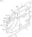
- Fig. 1 the holder body 1 'is shown in a longitudinal section, the cooling lubricant channels not lying in the plane of the section, but rather lying "deeper” in the holder body 1' into the plane of the figure.
- the holder body 1 ' has two sections; the clamping section 11, which is provided for coupling to the machine tool, and the receiving section 12, in which a cutting insert can be received.
- the parting holder 1 or the holder body 1 ' has a cutting tool seat 123, the shape and dimensions of which correspond to a specific cutting tool to be accommodated, for example an indexable insert.
- the cutting tool seat 123 can also have channel-like depressions transversely to the longitudinal direction of the holder body 1 ', although this is not shown in the figures.
- the cutting tool can be clamped in the cutting tool seat 123 by elastically deforming the slot 124 adjoining the cutting tool seat 123 by a tensioning device which exerts a tensioning force on the holder body normal to the direction in which the slot 124 extends.
- At the "closed end" of the slot 124 there is an end bore 124 'which provides additional elasticity and which reduces the notch effect at the slot end.
- the holder body 1 ' has fastening bores 13, which can also be threaded bores, which is not shown figuratively.
- the holder body 1 ' With the fastening bores 13, the holder body 1 'is coupled to a machine tool in a force-conducting manner, which can be done directly or indirectly; the holder body 1 'can be connected directly to a tool holder of a lathe, initially clamped in an adapter or it can be part of a parting holder with an elongated shaft.
- the holder body 1 ' has a greater thickness than in the receiving section 12, since the width of a cutting groove to be produced should be as small as possible. Sufficient space for movement for a body of revolution is created via the rounding 121, while the receiving section 12 is given rigidity.
- the holder body 1 ′ also has a central feed opening 14 for cooling lubricant, which is coupled to a cooling lubricant system of the machine tool. Cooling lubricant channels extend from the supply opening 14 in the holder body 1 '(see FIG Fig. 2 ), which each open into an outlet opening 16, 17, 18a, 18b.
- the parting holder 1 has four outlet openings 16, 17, 18ab, 18b;
- One outlet opening 18a, 18b is located on the side surfaces 122 ′′ below the cutting tool seat 123 and emerges at an angle from the surface, with one outlet opening 18a, 18b each on wall sections facing away from one another, which is illustrated by the dashed illustration of the outlet opening 18b;
- two outlet openings 16, 17 lie on the end faces 122 'of the holder body 1', an upper outlet opening 16 which is above the cutting tool seat 123 and a lower outlet opening 17.
- the parting holder 1 has several outlet openings 16, 17, 18a, 18b, which also can have different cross-sectional areas and flow rates, optimal chip evacuation and optimal cooling is achieved; during the lower end-side outlet opening 17 is designed to cool the cutting edge from below, the upper end-side outlet opening 16 is also used for chip removal and the side outlet openings 18a, 18b cools the cutting tool body from the side below, which contributes to the heating of the cutting tool body and the transfer of heat into to prevent the holder body 1 '.
- the longitudinal axes of the exiting coolant jets K are shown in dotted lines.
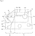
- Fig. 2 shows a side view of the in Fig. 1 Partial view shown, wherein the cut surface lies in the image plane. Hidden edges are shown in dashed lines, whereby the course of the cooling lubricant channels 19, 193, 194, 195 can be explained.
- the cooling lubricant channel 19, which kinks below the cutting tool seat 123 and runs parallel to the slot 124, extends downward from the supply opening 14 as the central supply point.
- the cooling lubricant channel 19 branches off into the cooling lubricant channel 193, which opens into the lateral outlet openings 18a, 18b on the side surface 122 ′′, and the cooling lubricant channel 195, which opens into the lower outlet opening 17 on the end face 122 '.
- the branch 191 is designed in a flow-favorable manner
- the cooling lubricant channel 194 also extends from the supply opening 14 and opens into the upper outlet opening 16 at the beveled section of the end face 122 '.
- the holder body 1 'with the described channel geometry cannot be produced with conventional primary forming and separating manufacturing processes, such as casting and / or milling / drilling, etc. It is therefore proposed to use a generative manufacturing method, in particular selective laser melting, for the production, as a result of which the holder body 1 ′ can be produced with little mechanical reworking.
- the finished holder body can be removed from the device for selective laser melting; this is then ready for use after the residues of the powdery starting material have been cleaned.
Landscapes
- Engineering & Computer Science (AREA)
- Mechanical Engineering (AREA)
- Cutting Tools, Boring Holders, And Turrets (AREA)
Claims (8)
- Support à tronçonner (1) avec- un corps de support en forme de plaque (1') qui présente un siège d'outil de coupe (123) et- une section de serrage (11) pour serrer le support à tronçonner (1) dans une machine-outil, dans lequel- au moins un premier canal de lubrifiant caloporteur (193) est présent dans le corps de support (1'), lequel présente au moins une ouverture de sortie (18a, 18b) sur une face latérale (122") du corps de support et sort en biais de la face latérale (122"), dans lequel une l'ouverture de sortie (18a, 18b) dans chaque cas existe a sections des murs des faces latérales (122") dont les sections des murs sont détournées l'une de l'autre sous le siège d'outil de coupe (123),- dans lequel l'ouverture de sortie (18a, 18b) est orientée de sorte qu'un jet de lubrifiant caloporteur (K) qui sort du canal de lubrifiant caloporteur (193) peut être dirigé latéralement par le bas sur une face d'un outil de coupe qui est reçu dans le siège d'outil de coupe (123),dans lequel le corps de support (1')- présente au moins un canal de lubrifiant caloporteur supérieur (194) qui débouche dans une ouverture de sortie supérieure (16) qui est présente sur une face frontale (122') du corps de support (1') et est orientée de sorte qu'un jet de lubrifiant caloporteur qui sort du canal de lubrifiant caloporteur (194) peut être dirigé du haut sur une arête de coupe d'un outil de coupe qui est reçu dans le siège d'outil de coupe (123) et- présente au moins un canal de lubrifiant caloporteur inférieur (195) qui débouche dans une ouverture de sortie inférieure (17) qui est présente sur une face frontale (122') du corps de support (1') et est orientée de sorte qu'un jet de lubrifiant caloporteur qui sort du canal de lubrifiant caloporteur (195) peut être dirigé du bas sur l'arête de coupe de l'outil de coupe qui est reçu dans le siège d'outil de coupe (123).
- Support à tronçonner (1) selon la revendication 1,
caractérisé en ce que
le corps de support (1') présente au moins une ouverture d'amenée (14) pour lubrifiant caloporteur qui est de préférence présente dans la section de serrage (11), dans lequel l'ouverture d'amenée (14) peut être reliée de manière fluidique à une source de lubrifiant caloporteur et le canal de lubrifiant caloporteur (193) s'étend de l'ouverture d'amenée (14) à l'ouverture de sortie (18a, 18b). - Support à tronçonner (1) selon la revendication 1 ou 2,
caractérisé en ce que
le canal de lubrifiant caloporteur (193) présente au moins un coudage qui est de préférence arrondi. - Support à tronçonner (1) selon au moins une des revendications 1 à 3,
caractérisé en ce que
le canal de lubrifiant caloporteur supérieur (194) et/ou le canal de lubrifiant caloporteur inférieur (195) est/sont issu(s) d'une ramification d'une section de canal de lubrifiant caloporteur commune, notamment du premier canal de lubrifiant caloporteur (19, 193) et/ou- au moins un des canaux de lubrifiant caloporteur (193, 194, 195) a une section transversale non circulaire, de préférence une section transversale ovale ou rectangulaire, de manière préférée entre toutes une section transversale ovale plate ou rectangulaire plate. - Support à tronçonner (1) selon au moins une des revendications 1 à 4,
caractérisé en ce que
une fente (124) dont la direction d'extension s'étend parallèlement à un plan de réception de l'outil de coupe s'étend du siège d'outil de coupe (123) dans le corps de support (1'). - Procédé de fabrication pour un support à tronçonner (1) selon au moins une des revendications 1 à 5 en utilisant un dispositif de fabrication assisté par ordinateur, comprenant les étapesa) dans le dispositif de fabrication assisté par ordinateur, chargement d'un ensemble de données de volume 3D qui décrit le corps de support (1') du support à tronçonner (1),b) mise à disposition d'un matériau de départ pulvérulent,c) fabrication par étape d'un assemblage de matériau du matériau de départ pulvérulent, fabrication par étape ce faisant du volume de corps de support en forme de plaque (1') avec- l'au moins un canal de lubrifiant caloporteur (193) qui a au moins une ouverture de sortie (18a, 18b) qui sort en biais d'une face latérale (122") sur la face latérale (122") du corps de support et est orientée de sorte qu'un jet de lubrifiant caloporteur (K) qui sort du canal de lubrifiant caloporteur (193) peut être dirigé latéralement par le bas sur une face d'un outil de coupe qui est reçu dans le siège d'outil de coupe (123), dans lequel une l'ouverture de sortie (18a, 18b) dans chaque cas existe a sections des murs des faces latérales (122") dont les sections des murs sont détournées l'une de l'autre sous le siège d'outil de coupe (123), et- avec l'au moins un canal de lubrifiant caloporteur supérieur (194) qui débouche dans une ouverture de sortie supérieure (16) qui est présente sur une face frontale (122') du corps de support (1') et qui est orientée de sorte qu'un jet de lubrifiant caloporteur (K) qui sort du canal de lubrifiant caloporteur (194) peut être dirigé par le haut sur un arête de coupe d'un outil de coupe qui est reçu dans le siège d'outil de coupe (123), et avec- l'au moins un canal de lubrifiant caloporteur inférieur (195) qui débouche dans une ouverture de sortie inférieure (17) qui est présente sur une face frontale (122') du corps de support (1') et qui est orientée de sorte qu'un jet de lubrifiant caloporteur (K) qui sort du canal de lubrifiant caloporteur (195) peut être dirigé par le bas sur un arête de coupe d'un outil de coupe qui est reçu dans le siège d'outil de coupe (123).
- Procédé de fabrication selon la revendication 6,
dans lequel une fusion du matériau de départ pulvérulent est réalisée à l'étape c). - Procédé de fabrication selon la revendication 6 ou 7,
caractérisé en ce que- le matériau de départ pulvérulent est une poudre métallique et/ou- le dispositif de fabrication assisté par ordinateur est un dispositif pour la fusion sélective par laser ou le frittage sélectif par laser.
Priority Applications (5)
| Application Number | Priority Date | Filing Date | Title |
|---|---|---|---|
| EP14000278.3A EP2898967B9 (fr) | 2014-01-27 | 2014-01-27 | Support d'outil de coupe, procédé de fabrication et utilisation d'un dispositif de fabrication génératif pour la fabrication d'un support d'outil de coupe |
| US15/113,975 US20160339523A1 (en) | 2014-01-27 | 2014-12-04 | Cut-Off Tool Holder and Production Method |
| PCT/EP2014/003238 WO2015110132A1 (fr) | 2014-01-27 | 2014-12-04 | Porte-lames de tronçonnage et procédé de production |
| JP2016547945A JP6412580B2 (ja) | 2014-01-27 | 2014-12-04 | 突切り工具ホルダおよび製造方法 |
| IL246906A IL246906B (en) | 2014-01-27 | 2016-07-24 | Holder for cutting tools and production method |
Applications Claiming Priority (1)
| Application Number | Priority Date | Filing Date | Title |
|---|---|---|---|
| EP14000278.3A EP2898967B9 (fr) | 2014-01-27 | 2014-01-27 | Support d'outil de coupe, procédé de fabrication et utilisation d'un dispositif de fabrication génératif pour la fabrication d'un support d'outil de coupe |
Publications (4)
| Publication Number | Publication Date |
|---|---|
| EP2898967A1 EP2898967A1 (fr) | 2015-07-29 |
| EP2898967B1 EP2898967B1 (fr) | 2017-01-25 |
| EP2898967B2 true EP2898967B2 (fr) | 2021-03-03 |
| EP2898967B9 EP2898967B9 (fr) | 2021-08-11 |
Family
ID=50028723
Family Applications (1)
| Application Number | Title | Priority Date | Filing Date |
|---|---|---|---|
| EP14000278.3A Active EP2898967B9 (fr) | 2014-01-27 | 2014-01-27 | Support d'outil de coupe, procédé de fabrication et utilisation d'un dispositif de fabrication génératif pour la fabrication d'un support d'outil de coupe |
Country Status (5)
| Country | Link |
|---|---|
| US (1) | US20160339523A1 (fr) |
| EP (1) | EP2898967B9 (fr) |
| JP (1) | JP6412580B2 (fr) |
| IL (1) | IL246906B (fr) |
| WO (1) | WO2015110132A1 (fr) |
Families Citing this family (28)
| Publication number | Priority date | Publication date | Assignee | Title |
|---|---|---|---|---|
| DE102014119295B4 (de) | 2014-12-19 | 2023-08-10 | Kennametal Inc. | Werkzeughalter für einen Schneideinsatz sowie Verfahren zur Herstellung des Werkzeughalters |
| JP6550759B2 (ja) * | 2015-01-23 | 2019-07-31 | 三菱マテリアル株式会社 | バイト |
| DE112016003345B4 (de) * | 2015-07-24 | 2023-11-16 | Kyocera Corporation | Schneidwerkzeug und Verfahren zur Herstellung eines maschinell-bearbeiteten Produkts unter Verwendung desselben |
| DE112016006041B4 (de) * | 2015-12-25 | 2024-05-16 | Kyocera Corporation | Halter für ein Schneidwerkzeug, Schneidwerkzeug und Verfahren zum Herstellen eines maschinell-bearbeiteten Produkts |
| US10201862B2 (en) * | 2016-09-07 | 2019-02-12 | Iscar, Ltd. | Cutting tool having a coolant chamber with an integrally formed coolant deflection portion and tool body |
| EP3219421A1 (fr) * | 2016-09-09 | 2017-09-20 | Seco Tools Ab | Porte-outils avec conduits d'alimentation en fluide pour co2 supercritique |
| DE102016120595A1 (de) * | 2016-10-27 | 2018-05-03 | Komet Group Gmbh | Zerspanungswerkzeug |
| DE102017110132A1 (de) * | 2017-05-10 | 2018-11-15 | Kennametal Inc. | Abstechdrehwerkzeug |
| JP6646011B2 (ja) * | 2017-06-01 | 2020-02-14 | 日本特殊陶業株式会社 | 切削工具用ホルダ及び切削工具 |
| US10300532B2 (en) * | 2017-06-26 | 2019-05-28 | Kennametal Inc. | Clamp for tool holder |
| DE102017123786A1 (de) * | 2017-10-12 | 2019-04-18 | Hartmetall-Werkzeugfabrik Paul Horn Gmbh | Halter für ein Nutstoßwerkzeug |
| CN107999797B (zh) * | 2017-11-30 | 2019-05-03 | 株洲钻石切削刀具股份有限公司 | 一种具有内冷通道的切槽刀具及内冷通道加工方法 |
| US11491594B2 (en) | 2018-01-08 | 2022-11-08 | Ford Motor Company | Tooling assembly with internal coolant passages for machines |
| WO2020065976A1 (fr) * | 2018-09-28 | 2020-04-02 | Sumitomo Electric Hardmetal Corp. | Outil de coupe, outil de tournage et procédé d'usinage d'une pièce |
| DE102018125767A1 (de) * | 2018-10-17 | 2020-04-23 | Hartmetall-Werkzeugfabrik Paul Horn Gmbh | Werkzeughalter und Werkzeug mit einem solchen Werkzeughalter |
| EP3867001A1 (fr) * | 2018-10-17 | 2021-08-25 | Hartmetall-Werkzeugfabrik Paul Horn GmbH | Porte-outil et outil muni d'un tel porte-outil |
| JP7058207B2 (ja) * | 2018-10-25 | 2022-04-21 | Dmg森精機株式会社 | 工作機械の製造方法、及び製造システム |
| JP7183916B2 (ja) * | 2019-03-29 | 2022-12-06 | 三菱マテリアル株式会社 | 溝入れ工具用ヘッド部材および溝入れ工具 |
| EP3815840B1 (fr) * | 2019-10-31 | 2023-10-04 | Sandvik Machining Solutions AB | Procédé de production d'une pièce d'outil |
| EP4171854B1 (fr) * | 2020-06-30 | 2024-08-21 | Iscar Ltd. | Lame de séparation indexable à canaux de fluide de refroidissement indirects |
| EP4205889A4 (fr) * | 2020-08-31 | 2024-10-09 | Mitsubishi Materials Corporation | Outil de rainurage |
| CZ309223B6 (cs) * | 2020-11-03 | 2022-06-01 | Západočeská Univerzita V Plzni | Nástroj pro obrábění |
| DE102021207539A1 (de) * | 2021-07-15 | 2023-01-19 | Karl-Heinz Arnold Gmbh | Verfahren zur Herstellung von Drehwerkzeugen und Drehwerkzeug |
| CZ2021594A3 (cs) * | 2021-12-23 | 2023-03-29 | Západočeská Univerzita V Plzni | Nástroj pro obrábění |
| US20240011526A1 (en) * | 2022-07-08 | 2024-01-11 | Kennametal Inc. | Stabilizing long and slender tools by hydrostatic bearing effect |
| US12434306B2 (en) * | 2022-10-25 | 2025-10-07 | Taegutec Ltd. | Cutting tool assembly |
| JP7647734B2 (ja) * | 2022-12-27 | 2025-03-18 | 株式会社タンガロイ | ブレード |
| EP4603215A1 (fr) * | 2024-02-15 | 2025-08-20 | CERATIZIT Austria Gesellschaft m.b.H. | Outil de tronçonnage par enlèvement de copeaux |
Citations (17)
| Publication number | Priority date | Publication date | Assignee | Title |
|---|---|---|---|---|
| JPS48107176U (fr) † | 1972-03-16 | 1973-12-12 | ||
| US3798725A (en) † | 1969-04-24 | 1974-03-26 | T Hanson | Cutting tool |
| US4863538A (en) † | 1986-10-17 | 1989-09-05 | Board Of Regents, The University Of Texas System | Method and apparatus for producing parts by selective sintering |
| JPH07227702A (ja) † | 1994-02-22 | 1995-08-29 | Mitsubishi Materials Corp | 溝入れ用工具 |
| US5833403A (en) † | 1995-10-06 | 1998-11-10 | Iscar Ltd. | Cutting tool assembly having an exchangeable adaptor |
| US6215093B1 (en) † | 1996-12-02 | 2001-04-10 | Fraunhofer-Gesellschaft Zur Foerderung Der Angewandten Forschung E.V. | Selective laser sintering at melting temperature |
| US6705805B2 (en) † | 2001-02-27 | 2004-03-16 | Sandvik Aktiebolag | Chip removing machining of a workpiece while applying high pressure cooling liquid |
| US7063487B2 (en) † | 2003-03-14 | 2006-06-20 | Sandvik Intellectual Property Ab | Tool and cutting insert for the fine turning of grooves in workpieces |
| US7134813B2 (en) † | 2002-12-19 | 2006-11-14 | Joerg Guehring | Cooling channel geometry |
| DE102004032093B4 (de) † | 2004-07-01 | 2007-05-16 | Cl Schutzrechtsverwaltungs Gmbh | Durch einen selektiven Lasersintervorgang (SLS) hergestelltes Bauteil |
| US20070283786A1 (en) † | 2006-06-09 | 2007-12-13 | Gregor Kappmeyer | Mehod for the manufacture of a cutting tool |
| JP2010105084A (ja) † | 2008-10-29 | 2010-05-13 | Kyocera Corp | ホルダおよびそれを用いた切削工具並びにそれを用いた切削方法 |
| US7959384B2 (en) † | 2006-11-28 | 2011-06-14 | Sandvik Intellectual Property Ab | Tool for chip removing machining and a basic body therefor |
| US20120230780A1 (en) † | 2011-03-07 | 2012-09-13 | Kennametal Inc. | Cutting assembly |
| DE102011016148A1 (de) † | 2011-03-28 | 2012-10-04 | Ernst Graf Gmbh | Werkzeug zur spanenden Bearbeitung eines Werkstücks mit seitlichem Kühlmittelaustritt |
| WO2012148233A2 (fr) † | 2011-04-28 | 2012-11-01 | Insstek, Inc. | Produit métallique ayant un espace interne formé à l'intérieur de celui-ci et son procédé de fabrication |
| EP2821167A1 (fr) † | 2013-06-28 | 2015-01-07 | Sandvik Intellectual Property AB | Outil pour usinage par enlèvement de copeaux et élément rapporté remplaçable de coupe destiné à être monté sur un outil |
Family Cites Families (10)
| Publication number | Priority date | Publication date | Assignee | Title |
|---|---|---|---|---|
| SE354213B (fr) * | 1972-04-10 | 1973-03-05 | Sandvik Ab | |
| DE10252040B3 (de) * | 2002-11-06 | 2004-01-22 | Manfred Scharmann | Werkzeug zum Schneiden von Gewinden |
| JP2602354Y2 (ja) * | 1993-03-25 | 2000-01-11 | 京セラ株式会社 | 旋削用工具ホルダー |
| JPH1076404A (ja) * | 1996-02-28 | 1998-03-24 | Sumitomo Electric Ind Ltd | 旋削用バイト |
| JPH11291101A (ja) * | 1998-04-13 | 1999-10-26 | Mitsubishi Materials Corp | 油穴付きバイト |
| NO330162B1 (no) * | 2006-06-28 | 2011-02-28 | Teeness Asa | Beholder for innforing i en verktoyholder, en verktoyholder samt et system |
| JP5559470B2 (ja) | 2008-10-29 | 2014-07-23 | 三菱マテリアル株式会社 | 内径加工工具および内径加工方法 |
| EP2822720B1 (fr) | 2012-03-06 | 2016-07-20 | Iscar Ltd. | Lame de séparation et support de lame configurés pour le transport de réfrigérant sous pression |
| JP5991574B2 (ja) * | 2012-03-16 | 2016-09-14 | パナソニックIpマネジメント株式会社 | 三次元形状造形物の製造方法 |
| DE202012004900U1 (de) | 2012-05-18 | 2012-06-15 | Karl-Heinz Arnold Gmbh | Schneidwerkzeug |
-
2014
- 2014-01-27 EP EP14000278.3A patent/EP2898967B9/fr active Active
- 2014-12-04 WO PCT/EP2014/003238 patent/WO2015110132A1/fr not_active Ceased
- 2014-12-04 JP JP2016547945A patent/JP6412580B2/ja not_active Expired - Fee Related
- 2014-12-04 US US15/113,975 patent/US20160339523A1/en not_active Abandoned
-
2016
- 2016-07-24 IL IL246906A patent/IL246906B/en active IP Right Grant
Patent Citations (18)
| Publication number | Priority date | Publication date | Assignee | Title |
|---|---|---|---|---|
| US3798725A (en) † | 1969-04-24 | 1974-03-26 | T Hanson | Cutting tool |
| JPS48107176U (fr) † | 1972-03-16 | 1973-12-12 | ||
| US4863538A (en) † | 1986-10-17 | 1989-09-05 | Board Of Regents, The University Of Texas System | Method and apparatus for producing parts by selective sintering |
| JPH07227702A (ja) † | 1994-02-22 | 1995-08-29 | Mitsubishi Materials Corp | 溝入れ用工具 |
| US5833403A (en) † | 1995-10-06 | 1998-11-10 | Iscar Ltd. | Cutting tool assembly having an exchangeable adaptor |
| US6215093B1 (en) † | 1996-12-02 | 2001-04-10 | Fraunhofer-Gesellschaft Zur Foerderung Der Angewandten Forschung E.V. | Selective laser sintering at melting temperature |
| US6705805B2 (en) † | 2001-02-27 | 2004-03-16 | Sandvik Aktiebolag | Chip removing machining of a workpiece while applying high pressure cooling liquid |
| US7134813B2 (en) † | 2002-12-19 | 2006-11-14 | Joerg Guehring | Cooling channel geometry |
| US7063487B2 (en) † | 2003-03-14 | 2006-06-20 | Sandvik Intellectual Property Ab | Tool and cutting insert for the fine turning of grooves in workpieces |
| DE102004032093B4 (de) † | 2004-07-01 | 2007-05-16 | Cl Schutzrechtsverwaltungs Gmbh | Durch einen selektiven Lasersintervorgang (SLS) hergestelltes Bauteil |
| US20070283786A1 (en) † | 2006-06-09 | 2007-12-13 | Gregor Kappmeyer | Mehod for the manufacture of a cutting tool |
| US7959384B2 (en) † | 2006-11-28 | 2011-06-14 | Sandvik Intellectual Property Ab | Tool for chip removing machining and a basic body therefor |
| JP2010105084A (ja) † | 2008-10-29 | 2010-05-13 | Kyocera Corp | ホルダおよびそれを用いた切削工具並びにそれを用いた切削方法 |
| US20120230780A1 (en) † | 2011-03-07 | 2012-09-13 | Kennametal Inc. | Cutting assembly |
| DE102011016148A1 (de) † | 2011-03-28 | 2012-10-04 | Ernst Graf Gmbh | Werkzeug zur spanenden Bearbeitung eines Werkstücks mit seitlichem Kühlmittelaustritt |
| US9346103B2 (en) † | 2011-03-28 | 2016-05-24 | Hartmetall-Werkzeugfabrik Paul Horn Gmbh | Tool for the machining of a workpiece with lateral coolant outlet |
| WO2012148233A2 (fr) † | 2011-04-28 | 2012-11-01 | Insstek, Inc. | Produit métallique ayant un espace interne formé à l'intérieur de celui-ci et son procédé de fabrication |
| EP2821167A1 (fr) † | 2013-06-28 | 2015-01-07 | Sandvik Intellectual Property AB | Outil pour usinage par enlèvement de copeaux et élément rapporté remplaçable de coupe destiné à être monté sur un outil |
Also Published As
| Publication number | Publication date |
|---|---|
| IL246906B (en) | 2020-05-31 |
| WO2015110132A1 (fr) | 2015-07-30 |
| EP2898967B9 (fr) | 2021-08-11 |
| JP6412580B2 (ja) | 2018-10-24 |
| IL246906A0 (en) | 2016-09-29 |
| US20160339523A1 (en) | 2016-11-24 |
| EP2898967A1 (fr) | 2015-07-29 |
| EP2898967B1 (fr) | 2017-01-25 |
| JP2017503669A (ja) | 2017-02-02 |
Similar Documents
| Publication | Publication Date | Title |
|---|---|---|
| EP2898967B2 (fr) | Support d'outil de coupe, procédé de fabrication et utilisation d'un dispositif de fabrication génératif pour la fabrication d'un support d'outil de coupe | |
| DE102014119295B4 (de) | Werkzeughalter für einen Schneideinsatz sowie Verfahren zur Herstellung des Werkzeughalters | |
| DE102014012481A1 (de) | Scheibenfräser und Herstellverfahren | |
| DE10163473C1 (de) | Werkzeug zur spanabtragenden Bearbeitung von Rohrenden | |
| EP3519130B2 (fr) | Lame de separation de tournage | |
| DE4342557A1 (de) | Wendeschneidplatten zum Passungs- und Gewindefräsen ins volle Material und dazu einen einfachen Plattensitz | |
| EP2664400B1 (fr) | Outil de coupe | |
| EP2911817B1 (fr) | Dispositif de serrage avec coin doté d'un conduit de fluide de refroidissement et procédé de fabrication d'un tel dispositif de serrage | |
| DE102017126931B4 (de) | Werkzeuganordnung mit Schneidkörper sowie Verfahren zum Kühlen des Schneidkörpers | |
| DE102017131368A1 (de) | Metallschneidwerkzeug, insbesondere ein reibwerkzeug und ein verfahren zum herstellen desselben | |
| DE102017122054A1 (de) | Schneidwerkzeug sowie Verfahren zur Herstellung eines Schneidwerkzeugs | |
| DE102016221518A1 (de) | Werkzeughalter für eine Zerspanungsmaschine und Verfahren zum Herstellen eines solchen | |
| WO2021175639A1 (fr) | Fraise et procédé de fabrication d'une partie de coupe d'une fraise | |
| WO2015166065A1 (fr) | Foret fabriqué à l'aide d'un procédé de frittage laser | |
| EP3418025A1 (fr) | Dispositif de déviation permettant de dévier un flux de matière fondue à l'intérieur d'une plaque de distribution | |
| EP1979119B1 (fr) | Systeme d'outil | |
| WO2022161680A1 (fr) | Élément de coupe et outil de coupe de métal | |
| DE102007016994B4 (de) | Schneideinsatz für ein Bohrwerkzeug sowie Bohrwerkzeug | |
| DE102004008166A1 (de) | Werkzeug zur spanenden Bearbeitung von Präzisionsbohrungen | |
| DE102020112808A1 (de) | Schneidwerkzeug und Verfahren zur Herstellung eines Schneidwerkzeugs | |
| DE102011008998B4 (de) | Verfahren zum spanenden Bearbeiten eines Werkstücks | |
| EP4484036A1 (fr) | Dispositif, système et procédé de refroidissement d'un outil | |
| EP4735197A1 (fr) | Dispositif, système et procédé de refroidissement d'un outil | |
| DE102017130014A1 (de) | Umlenkvorrichtung zur Umlenkung eines Schmelzeflusses innerhalb einer Verteilerplatte | |
| DE102016008282B4 (de) | Verfahren zur Temperierung einer Eingriffskontur eines Werkzeugeinsatzes eines Formgebungswerkzeugs zur Kaltumformung von Metallwerkstoffen sowie Formgebungswerkzeug zur Durchführung des Verfahrens |
Legal Events
| Date | Code | Title | Description |
|---|---|---|---|
| PUAI | Public reference made under article 153(3) epc to a published international application that has entered the european phase |
Free format text: ORIGINAL CODE: 0009012 |
|
| 17P | Request for examination filed |
Effective date: 20140127 |
|
| AK | Designated contracting states |
Kind code of ref document: A1 Designated state(s): AL AT BE BG CH CY CZ DE DK EE ES FI FR GB GR HR HU IE IS IT LI LT LU LV MC MK MT NL NO PL PT RO RS SE SI SK SM TR |
|
| AX | Request for extension of the european patent |
Extension state: BA ME |
|
| 17P | Request for examination filed |
Effective date: 20150804 |
|
| RBV | Designated contracting states (corrected) |
Designated state(s): AL AT BE BG CH CY CZ DE DK EE ES FI FR GB GR HR HU IE IS IT LI LT LU LV MC MK MT NL NO PL PT RO RS SE SI SK SM TR |
|
| GRAP | Despatch of communication of intention to grant a patent |
Free format text: ORIGINAL CODE: EPIDOSNIGR1 |
|
| INTG | Intention to grant announced |
Effective date: 20160728 |
|
| GRAS | Grant fee paid |
Free format text: ORIGINAL CODE: EPIDOSNIGR3 |
|
| STAA | Information on the status of an ep patent application or granted ep patent |
Free format text: STATUS: GRANT OF PATENT IS INTENDED |
|
| GRAA | (expected) grant |
Free format text: ORIGINAL CODE: 0009210 |
|
| STAA | Information on the status of an ep patent application or granted ep patent |
Free format text: STATUS: THE PATENT HAS BEEN GRANTED |
|
| AK | Designated contracting states |
Kind code of ref document: B1 Designated state(s): AL AT BE BG CH CY CZ DE DK EE ES FI FR GB GR HR HU IE IS IT LI LT LU LV MC MK MT NL NO PL PT RO RS SE SI SK SM TR |
|
| REG | Reference to a national code |
Ref country code: GB Ref legal event code: FG4D Free format text: NOT ENGLISH |
|
| REG | Reference to a national code |
Ref country code: CH Ref legal event code: EP |
|
| REG | Reference to a national code |
Ref country code: AT Ref legal event code: REF Ref document number: 863824 Country of ref document: AT Kind code of ref document: T Effective date: 20170215 |
|
| REG | Reference to a national code |
Ref country code: IE Ref legal event code: FG4D Free format text: LANGUAGE OF EP DOCUMENT: GERMAN |
|
| REG | Reference to a national code |
Ref country code: DE Ref legal event code: R096 Ref document number: 502014002511 Country of ref document: DE |
|
| REG | Reference to a national code |
Ref country code: NL Ref legal event code: FP |
|
| REG | Reference to a national code |
Ref country code: CH Ref legal event code: NV Representative=s name: FIAMMENGHI-FIAMMENGHI, CH |
|
| REG | Reference to a national code |
Ref country code: SE Ref legal event code: TRGR |
|
| REG | Reference to a national code |
Ref country code: FR Ref legal event code: PLFP Year of fee payment: 4 |
|
| REG | Reference to a national code |
Ref country code: LT Ref legal event code: MG4D |
|
| PG25 | Lapsed in a contracting state [announced via postgrant information from national office to epo] |
Ref country code: BE Free format text: LAPSE BECAUSE OF NON-PAYMENT OF DUE FEES Effective date: 20170131 |
|
| PG25 | Lapsed in a contracting state [announced via postgrant information from national office to epo] |
Ref country code: GR Free format text: LAPSE BECAUSE OF FAILURE TO SUBMIT A TRANSLATION OF THE DESCRIPTION OR TO PAY THE FEE WITHIN THE PRESCRIBED TIME-LIMIT Effective date: 20170426 Ref country code: FI Free format text: LAPSE BECAUSE OF FAILURE TO SUBMIT A TRANSLATION OF THE DESCRIPTION OR TO PAY THE FEE WITHIN THE PRESCRIBED TIME-LIMIT Effective date: 20170125 Ref country code: NO Free format text: LAPSE BECAUSE OF FAILURE TO SUBMIT A TRANSLATION OF THE DESCRIPTION OR TO PAY THE FEE WITHIN THE PRESCRIBED TIME-LIMIT Effective date: 20170425 Ref country code: IS Free format text: LAPSE BECAUSE OF FAILURE TO SUBMIT A TRANSLATION OF THE DESCRIPTION OR TO PAY THE FEE WITHIN THE PRESCRIBED TIME-LIMIT Effective date: 20170525 Ref country code: HR Free format text: LAPSE BECAUSE OF FAILURE TO SUBMIT A TRANSLATION OF THE DESCRIPTION OR TO PAY THE FEE WITHIN THE PRESCRIBED TIME-LIMIT Effective date: 20170125 Ref country code: LT Free format text: LAPSE BECAUSE OF FAILURE TO SUBMIT A TRANSLATION OF THE DESCRIPTION OR TO PAY THE FEE WITHIN THE PRESCRIBED TIME-LIMIT Effective date: 20170125 |
|
| PG25 | Lapsed in a contracting state [announced via postgrant information from national office to epo] |
Ref country code: LV Free format text: LAPSE BECAUSE OF FAILURE TO SUBMIT A TRANSLATION OF THE DESCRIPTION OR TO PAY THE FEE WITHIN THE PRESCRIBED TIME-LIMIT Effective date: 20170125 Ref country code: PT Free format text: LAPSE BECAUSE OF FAILURE TO SUBMIT A TRANSLATION OF THE DESCRIPTION OR TO PAY THE FEE WITHIN THE PRESCRIBED TIME-LIMIT Effective date: 20170525 Ref country code: RS Free format text: LAPSE BECAUSE OF FAILURE TO SUBMIT A TRANSLATION OF THE DESCRIPTION OR TO PAY THE FEE WITHIN THE PRESCRIBED TIME-LIMIT Effective date: 20170125 Ref country code: BG Free format text: LAPSE BECAUSE OF FAILURE TO SUBMIT A TRANSLATION OF THE DESCRIPTION OR TO PAY THE FEE WITHIN THE PRESCRIBED TIME-LIMIT Effective date: 20170425 Ref country code: ES Free format text: LAPSE BECAUSE OF FAILURE TO SUBMIT A TRANSLATION OF THE DESCRIPTION OR TO PAY THE FEE WITHIN THE PRESCRIBED TIME-LIMIT Effective date: 20170125 Ref country code: PL Free format text: LAPSE BECAUSE OF FAILURE TO SUBMIT A TRANSLATION OF THE DESCRIPTION OR TO PAY THE FEE WITHIN THE PRESCRIBED TIME-LIMIT Effective date: 20170125 |
|
| REG | Reference to a national code |
Ref country code: DE Ref legal event code: R026 Ref document number: 502014002511 Country of ref document: DE |
|
| PG25 | Lapsed in a contracting state [announced via postgrant information from national office to epo] |
Ref country code: CZ Free format text: LAPSE BECAUSE OF FAILURE TO SUBMIT A TRANSLATION OF THE DESCRIPTION OR TO PAY THE FEE WITHIN THE PRESCRIBED TIME-LIMIT Effective date: 20170125 Ref country code: SK Free format text: LAPSE BECAUSE OF FAILURE TO SUBMIT A TRANSLATION OF THE DESCRIPTION OR TO PAY THE FEE WITHIN THE PRESCRIBED TIME-LIMIT Effective date: 20170125 Ref country code: EE Free format text: LAPSE BECAUSE OF FAILURE TO SUBMIT A TRANSLATION OF THE DESCRIPTION OR TO PAY THE FEE WITHIN THE PRESCRIBED TIME-LIMIT Effective date: 20170125 Ref country code: RO Free format text: LAPSE BECAUSE OF FAILURE TO SUBMIT A TRANSLATION OF THE DESCRIPTION OR TO PAY THE FEE WITHIN THE PRESCRIBED TIME-LIMIT Effective date: 20170125 |
|
| REG | Reference to a national code |
Ref country code: IE Ref legal event code: MM4A |
|
| PLBI | Opposition filed |
Free format text: ORIGINAL CODE: 0009260 |
|
| PG25 | Lapsed in a contracting state [announced via postgrant information from national office to epo] |
Ref country code: MC Free format text: LAPSE BECAUSE OF FAILURE TO SUBMIT A TRANSLATION OF THE DESCRIPTION OR TO PAY THE FEE WITHIN THE PRESCRIBED TIME-LIMIT Effective date: 20170125 Ref country code: SM Free format text: LAPSE BECAUSE OF FAILURE TO SUBMIT A TRANSLATION OF THE DESCRIPTION OR TO PAY THE FEE WITHIN THE PRESCRIBED TIME-LIMIT Effective date: 20170125 Ref country code: LU Free format text: LAPSE BECAUSE OF NON-PAYMENT OF DUE FEES Effective date: 20170127 Ref country code: DK Free format text: LAPSE BECAUSE OF FAILURE TO SUBMIT A TRANSLATION OF THE DESCRIPTION OR TO PAY THE FEE WITHIN THE PRESCRIBED TIME-LIMIT Effective date: 20170125 |
|
| PLAX | Notice of opposition and request to file observation + time limit sent |
Free format text: ORIGINAL CODE: EPIDOSNOBS2 |
|
| 26 | Opposition filed |
Opponent name: ISCAR LTD. Effective date: 20171025 |
|
| REG | Reference to a national code |
Ref country code: FR Ref legal event code: PLFP Year of fee payment: 5 |
|
| REG | Reference to a national code |
Ref country code: BE Ref legal event code: MM Effective date: 20170131 |
|
| PG25 | Lapsed in a contracting state [announced via postgrant information from national office to epo] |
Ref country code: IE Free format text: LAPSE BECAUSE OF NON-PAYMENT OF DUE FEES Effective date: 20170127 Ref country code: SI Free format text: LAPSE BECAUSE OF FAILURE TO SUBMIT A TRANSLATION OF THE DESCRIPTION OR TO PAY THE FEE WITHIN THE PRESCRIBED TIME-LIMIT Effective date: 20170125 |
|
| PLBB | Reply of patent proprietor to notice(s) of opposition received |
Free format text: ORIGINAL CODE: EPIDOSNOBS3 |
|
| PG25 | Lapsed in a contracting state [announced via postgrant information from national office to epo] |
Ref country code: MT Free format text: LAPSE BECAUSE OF FAILURE TO SUBMIT A TRANSLATION OF THE DESCRIPTION OR TO PAY THE FEE WITHIN THE PRESCRIBED TIME-LIMIT Effective date: 20170125 |
|
| PG25 | Lapsed in a contracting state [announced via postgrant information from national office to epo] |
Ref country code: HU Free format text: LAPSE BECAUSE OF FAILURE TO SUBMIT A TRANSLATION OF THE DESCRIPTION OR TO PAY THE FEE WITHIN THE PRESCRIBED TIME-LIMIT; INVALID AB INITIO Effective date: 20140127 |
|
| PG25 | Lapsed in a contracting state [announced via postgrant information from national office to epo] |
Ref country code: CY Free format text: LAPSE BECAUSE OF FAILURE TO SUBMIT A TRANSLATION OF THE DESCRIPTION OR TO PAY THE FEE WITHIN THE PRESCRIBED TIME-LIMIT Effective date: 20170125 |
|
| PG25 | Lapsed in a contracting state [announced via postgrant information from national office to epo] |
Ref country code: MK Free format text: LAPSE BECAUSE OF FAILURE TO SUBMIT A TRANSLATION OF THE DESCRIPTION OR TO PAY THE FEE WITHIN THE PRESCRIBED TIME-LIMIT Effective date: 20170125 |
|
| PG25 | Lapsed in a contracting state [announced via postgrant information from national office to epo] |
Ref country code: TR Free format text: LAPSE BECAUSE OF FAILURE TO SUBMIT A TRANSLATION OF THE DESCRIPTION OR TO PAY THE FEE WITHIN THE PRESCRIBED TIME-LIMIT Effective date: 20170125 |
|
| PG25 | Lapsed in a contracting state [announced via postgrant information from national office to epo] |
Ref country code: AL Free format text: LAPSE BECAUSE OF FAILURE TO SUBMIT A TRANSLATION OF THE DESCRIPTION OR TO PAY THE FEE WITHIN THE PRESCRIBED TIME-LIMIT Effective date: 20170125 |
|
| PUAH | Patent maintained in amended form |
Free format text: ORIGINAL CODE: 0009272 |
|
| STAA | Information on the status of an ep patent application or granted ep patent |
Free format text: STATUS: PATENT MAINTAINED AS AMENDED |
|
| REG | Reference to a national code |
Ref country code: CH Ref legal event code: AELC |
|
| 27A | Patent maintained in amended form |
Effective date: 20210303 |
|
| AK | Designated contracting states |
Kind code of ref document: B2 Designated state(s): AL AT BE BG CH CY CZ DE DK EE ES FI FR GB GR HR HU IE IS IT LI LT LU LV MC MK MT NL NO PL PT RO RS SE SI SK SM TR |
|
| REG | Reference to a national code |
Ref country code: DE Ref legal event code: R102 Ref document number: 502014002511 Country of ref document: DE |
|
| REG | Reference to a national code |
Ref country code: SE Ref legal event code: RPEO |
|
| REG | Reference to a national code |
Ref country code: NL Ref legal event code: FP |
|
| PGFP | Annual fee paid to national office [announced via postgrant information from national office to epo] |
Ref country code: FR Payment date: 20230123 Year of fee payment: 10 Ref country code: CH Payment date: 20230130 Year of fee payment: 10 Ref country code: AT Payment date: 20230118 Year of fee payment: 10 |
|
| PGFP | Annual fee paid to national office [announced via postgrant information from national office to epo] |
Ref country code: SE Payment date: 20230123 Year of fee payment: 10 Ref country code: IT Payment date: 20230131 Year of fee payment: 10 Ref country code: GB Payment date: 20230117 Year of fee payment: 10 |
|
| PGFP | Annual fee paid to national office [announced via postgrant information from national office to epo] |
Ref country code: NL Payment date: 20230124 Year of fee payment: 10 |
|
| REG | Reference to a national code |
Ref country code: CH Ref legal event code: PL |
|
| REG | Reference to a national code |
Ref country code: SE Ref legal event code: EUG |
|
| REG | Reference to a national code |
Ref country code: NL Ref legal event code: MM Effective date: 20240201 |
|
| REG | Reference to a national code |
Ref country code: AT Ref legal event code: MM01 Ref document number: 863824 Country of ref document: AT Kind code of ref document: T Effective date: 20240127 |
|
| GBPC | Gb: european patent ceased through non-payment of renewal fee |
Effective date: 20240127 |
|
| PG25 | Lapsed in a contracting state [announced via postgrant information from national office to epo] |
Ref country code: GB Free format text: LAPSE BECAUSE OF NON-PAYMENT OF DUE FEES Effective date: 20240127 |
|
| PG25 | Lapsed in a contracting state [announced via postgrant information from national office to epo] |
Ref country code: FR Free format text: LAPSE BECAUSE OF NON-PAYMENT OF DUE FEES Effective date: 20240131 |
|
| PG25 | Lapsed in a contracting state [announced via postgrant information from national office to epo] |
Ref country code: NL Free format text: LAPSE BECAUSE OF NON-PAYMENT OF DUE FEES Effective date: 20240201 |
|
| PG25 | Lapsed in a contracting state [announced via postgrant information from national office to epo] |
Ref country code: CH Free format text: LAPSE BECAUSE OF NON-PAYMENT OF DUE FEES Effective date: 20240131 |
|
| PG25 | Lapsed in a contracting state [announced via postgrant information from national office to epo] |
Ref country code: AT Free format text: LAPSE BECAUSE OF NON-PAYMENT OF DUE FEES Effective date: 20240127 |
|
| PG25 | Lapsed in a contracting state [announced via postgrant information from national office to epo] |
Ref country code: NL Free format text: LAPSE BECAUSE OF NON-PAYMENT OF DUE FEES Effective date: 20240201 Ref country code: GB Free format text: LAPSE BECAUSE OF NON-PAYMENT OF DUE FEES Effective date: 20240127 Ref country code: FR Free format text: LAPSE BECAUSE OF NON-PAYMENT OF DUE FEES Effective date: 20240131 Ref country code: CH Free format text: LAPSE BECAUSE OF NON-PAYMENT OF DUE FEES Effective date: 20240131 Ref country code: AT Free format text: LAPSE BECAUSE OF NON-PAYMENT OF DUE FEES Effective date: 20240127 |
|
| PG25 | Lapsed in a contracting state [announced via postgrant information from national office to epo] |
Ref country code: IT Free format text: LAPSE BECAUSE OF NON-PAYMENT OF DUE FEES Effective date: 20240127 |
|
| PG25 | Lapsed in a contracting state [announced via postgrant information from national office to epo] |
Ref country code: SE Free format text: LAPSE BECAUSE OF NON-PAYMENT OF DUE FEES Effective date: 20240128 |
|
| PGFP | Annual fee paid to national office [announced via postgrant information from national office to epo] |
Ref country code: DE Payment date: 20260217 Year of fee payment: 13 |