EP2898986A2 - Appareil et procédé pour traiter un composant rotatif - Google Patents
Appareil et procédé pour traiter un composant rotatif Download PDFInfo
- Publication number
- EP2898986A2 EP2898986A2 EP15152565.6A EP15152565A EP2898986A2 EP 2898986 A2 EP2898986 A2 EP 2898986A2 EP 15152565 A EP15152565 A EP 15152565A EP 2898986 A2 EP2898986 A2 EP 2898986A2
- Authority
- EP
- European Patent Office
- Prior art keywords
- component
- rotatable
- machining tool
- sliding engagement
- engagement member
- Prior art date
- Legal status (The legal status is an assumption and is not a legal conclusion. Google has not performed a legal analysis and makes no representation as to the accuracy of the status listed.)
- Withdrawn
Links
- 238000000034 method Methods 0.000 title claims abstract description 28
- 238000003754 machining Methods 0.000 claims abstract description 52
- 239000004575 stone Substances 0.000 claims description 26
- 125000006850 spacer group Chemical group 0.000 claims description 17
- 230000000153 supplemental effect Effects 0.000 claims description 13
- 239000012260 resinous material Substances 0.000 claims description 3
- 239000000463 material Substances 0.000 description 18
- 230000008878 coupling Effects 0.000 description 15
- 238000010168 coupling process Methods 0.000 description 15
- 238000005859 coupling reaction Methods 0.000 description 15
- 238000011282 treatment Methods 0.000 description 4
- 239000000203 mixture Substances 0.000 description 3
- 230000008569 process Effects 0.000 description 3
- 229910052751 metal Inorganic materials 0.000 description 2
- 239000002184 metal Substances 0.000 description 2
- RYGMFSIKBFXOCR-UHFFFAOYSA-N Copper Chemical compound [Cu] RYGMFSIKBFXOCR-UHFFFAOYSA-N 0.000 description 1
- 229910000831 Steel Inorganic materials 0.000 description 1
- 239000003082 abrasive agent Substances 0.000 description 1
- 229910052782 aluminium Inorganic materials 0.000 description 1
- XAGFODPZIPBFFR-UHFFFAOYSA-N aluminium Chemical compound [Al] XAGFODPZIPBFFR-UHFFFAOYSA-N 0.000 description 1
- 238000013459 approach Methods 0.000 description 1
- 229910052802 copper Inorganic materials 0.000 description 1
- 239000010949 copper Substances 0.000 description 1
- 230000007547 defect Effects 0.000 description 1
- 230000000694 effects Effects 0.000 description 1
- 230000005611 electricity Effects 0.000 description 1
- 238000011065 in-situ storage Methods 0.000 description 1
- 230000007246 mechanism Effects 0.000 description 1
- TWNQGVIAIRXVLR-UHFFFAOYSA-N oxo(oxoalumanyloxy)alumane Chemical compound O=[Al]O[Al]=O TWNQGVIAIRXVLR-UHFFFAOYSA-N 0.000 description 1
- 229920000642 polymer Polymers 0.000 description 1
- 230000008439 repair process Effects 0.000 description 1
- HBMJWWWQQXIZIP-UHFFFAOYSA-N silicon carbide Chemical compound [Si+]#[C-] HBMJWWWQQXIZIP-UHFFFAOYSA-N 0.000 description 1
- 229910010271 silicon carbide Inorganic materials 0.000 description 1
- 230000000087 stabilizing effect Effects 0.000 description 1
- 239000010959 steel Substances 0.000 description 1
- 238000004381 surface treatment Methods 0.000 description 1
- 229920001169 thermoplastic Polymers 0.000 description 1
- 239000004416 thermosoftening plastic Substances 0.000 description 1
Images




Classifications
-
- B—PERFORMING OPERATIONS; TRANSPORTING
- B24—GRINDING; POLISHING
- B24B—MACHINES, DEVICES, OR PROCESSES FOR GRINDING OR POLISHING; DRESSING OR CONDITIONING OF ABRADING SURFACES; FEEDING OF GRINDING, POLISHING, OR LAPPING AGENTS
- B24B5/00—Machines or devices designed for grinding surfaces of revolution on work, including those which also grind adjacent plane surfaces; Accessories therefor
- B24B5/36—Single-purpose machines or devices
-
- B—PERFORMING OPERATIONS; TRANSPORTING
- B24—GRINDING; POLISHING
- B24B—MACHINES, DEVICES, OR PROCESSES FOR GRINDING OR POLISHING; DRESSING OR CONDITIONING OF ABRADING SURFACES; FEEDING OF GRINDING, POLISHING, OR LAPPING AGENTS
- B24B23/00—Portable grinding machines, e.g. hand-guided; Accessories therefor
- B24B23/02—Portable grinding machines, e.g. hand-guided; Accessories therefor with rotating grinding tools; Accessories therefor
- B24B23/028—Angle tools
-
- B—PERFORMING OPERATIONS; TRANSPORTING
- B23—MACHINE TOOLS; METAL-WORKING NOT OTHERWISE PROVIDED FOR
- B23P—METAL-WORKING NOT OTHERWISE PROVIDED FOR; COMBINED OPERATIONS; UNIVERSAL MACHINE TOOLS
- B23P6/00—Restoring or reconditioning objects
- B23P6/04—Repairing fractures or cracked metal parts or products, e.g. castings
-
- B—PERFORMING OPERATIONS; TRANSPORTING
- B24—GRINDING; POLISHING
- B24B—MACHINES, DEVICES, OR PROCESSES FOR GRINDING OR POLISHING; DRESSING OR CONDITIONING OF ABRADING SURFACES; FEEDING OF GRINDING, POLISHING, OR LAPPING AGENTS
- B24B19/00—Single-purpose machines or devices for particular grinding operations not covered by any other main group
- B24B19/14—Single-purpose machines or devices for particular grinding operations not covered by any other main group for grinding turbine blades, propeller blades or the like
-
- B—PERFORMING OPERATIONS; TRANSPORTING
- B24—GRINDING; POLISHING
- B24B—MACHINES, DEVICES, OR PROCESSES FOR GRINDING OR POLISHING; DRESSING OR CONDITIONING OF ABRADING SURFACES; FEEDING OF GRINDING, POLISHING, OR LAPPING AGENTS
- B24B23/00—Portable grinding machines, e.g. hand-guided; Accessories therefor
- B24B23/08—Portable grinding machines designed for fastening on workpieces or other parts of particular section, e.g. for grinding commutators
-
- B—PERFORMING OPERATIONS; TRANSPORTING
- B24—GRINDING; POLISHING
- B24B—MACHINES, DEVICES, OR PROCESSES FOR GRINDING OR POLISHING; DRESSING OR CONDITIONING OF ABRADING SURFACES; FEEDING OF GRINDING, POLISHING, OR LAPPING AGENTS
- B24B27/00—Other grinding machines or devices
- B24B27/0084—Other grinding machines or devices the grinding wheel support being angularly adjustable
-
- B—PERFORMING OPERATIONS; TRANSPORTING
- B24—GRINDING; POLISHING
- B24B—MACHINES, DEVICES, OR PROCESSES FOR GRINDING OR POLISHING; DRESSING OR CONDITIONING OF ABRADING SURFACES; FEEDING OF GRINDING, POLISHING, OR LAPPING AGENTS
- B24B39/00—Burnishing machines or devices, i.e. requiring pressure members for compacting the surface zone; Accessories therefor
- B24B39/006—Peening and tools therefor
-
- B—PERFORMING OPERATIONS; TRANSPORTING
- B24—GRINDING; POLISHING
- B24B—MACHINES, DEVICES, OR PROCESSES FOR GRINDING OR POLISHING; DRESSING OR CONDITIONING OF ABRADING SURFACES; FEEDING OF GRINDING, POLISHING, OR LAPPING AGENTS
- B24B5/00—Machines or devices designed for grinding surfaces of revolution on work, including those which also grind adjacent plane surfaces; Accessories therefor
- B24B5/02—Machines or devices designed for grinding surfaces of revolution on work, including those which also grind adjacent plane surfaces; Accessories therefor involving centres or chucks for holding work
- B24B5/04—Machines or devices designed for grinding surfaces of revolution on work, including those which also grind adjacent plane surfaces; Accessories therefor involving centres or chucks for holding work for grinding cylindrical surfaces externally
-
- B—PERFORMING OPERATIONS; TRANSPORTING
- B24—GRINDING; POLISHING
- B24B—MACHINES, DEVICES, OR PROCESSES FOR GRINDING OR POLISHING; DRESSING OR CONDITIONING OF ABRADING SURFACES; FEEDING OF GRINDING, POLISHING, OR LAPPING AGENTS
- B24B5/00—Machines or devices designed for grinding surfaces of revolution on work, including those which also grind adjacent plane surfaces; Accessories therefor
- B24B5/35—Accessories
-
- F—MECHANICAL ENGINEERING; LIGHTING; HEATING; WEAPONS; BLASTING
- F01—MACHINES OR ENGINES IN GENERAL; ENGINE PLANTS IN GENERAL; STEAM ENGINES
- F01D—NON-POSITIVE DISPLACEMENT MACHINES OR ENGINES, e.g. STEAM TURBINES
- F01D25/00—Component parts, details, or accessories, not provided for in, or of interest apart from, other groups
- F01D25/28—Supporting or mounting arrangements, e.g. for turbine casing
- F01D25/285—Temporary support structures, e.g. for testing, assembling, installing, repairing; Assembly methods using such structures
-
- F—MECHANICAL ENGINEERING; LIGHTING; HEATING; WEAPONS; BLASTING
- F01—MACHINES OR ENGINES IN GENERAL; ENGINE PLANTS IN GENERAL; STEAM ENGINES
- F01D—NON-POSITIVE DISPLACEMENT MACHINES OR ENGINES, e.g. STEAM TURBINES
- F01D5/00—Blades; Blade-carrying members; Heating, heat-insulating, cooling or antivibration means on the blades or the members
- F01D5/005—Repairing methods or devices
Definitions
- Embodiments of the present disclosure relate generally to treating the surface of a rotatable component. More specifically, the present disclosure includes an apparatus and method for treating a rotatable component such as a turbine spacer or a turbine wheel.
- various turbine sections typically include substantially circular "spacers" positioned between different turbine wheel stages. Each of these spacers may be coaxial with opposing nozzle diaphragms of the turbine apparatus. Although a turbine apparatus typically includes a set amount of clearance between a spacer and an opposing nozzle diaphragm, some spacers and nozzle diaphragms may contact each other while the turbine operates. Certain types of stress experienced by the turbine spacer can cause "stress risers" to form on the surface of the spacer.
- stress risers typically requires an on-site repair to reduce or remove the stress risers from the surface of the spacer.
- stress risers can be removed by rotating the spacer to a particular position, manually grinding the stress riser with a grinding tool, and then rotating the spacer to reach other stress risers if needed.
- the manual treatment of stress risers can be a costly and time-consuming process.
- human errors during the treatment can create non-uniform turbine spacers or other types of workpieces.
- stress can be intentionally introduced to a spacer or other rotating component by "peening" the surface of the component. Peening can be implemented by similar manually implemented techniques, and therefore may incur similar costs.
- a first aspect of the present disclosure provides an apparatus.
- the apparatus can include: a sliding engagement member configured to slidably engage a portion of a rotating component that is temporarily stationary; and a tool engaging member for positioning a machining tool relative to the rotating component to machine a surface of the rotating component, wherein the tool engaging member is rotatable to one of a plurality of angles relative to the sliding engagement member.
- a second aspect of the present disclosure provides a method of treating a rotatable turbine component.
- the method can include: slidably engaging a sliding engagement member of a machining tool to the rotatable turbine component such that an operative head of the machining tool is substantially aligned with a surface of the rotatable turbine component; contacting the surface of the rotatable turbine component with the operative head of the machining tool; and selectively rotating the rotatable turbine component relative to the operative head of the machining tool, wherein the operative head of the tool treats the surface of the rotatable turbine component.
- a third aspect of the present disclosure provides an apparatus.
- the apparatus can include: a sliding engagement member configured to slidably engage a portion of a rotatable turbine component, wherein the sliding engagement member further includes: a projecting section configured to slidably engage a recessed portion of the rotatable turbine component, and a recess configured to slidably engage a projecting portion of the rotatable turbine component; and a tool engaging member for positioning a machining tool relative to the rotatable turbine component to machine a surface of the rotatable turbine component, wherein the tool engaging member is rotatable to one of a plurality of angles relative to the sliding engagement member.
- Embodiments of the present disclosure can include an apparatus.
- the apparatus can include a sliding engagement member which may be designed to slidably engage a portion of a rotatable component. At the time of sliding engagement between a rotating component and the sliding engagement member, the rotating component may be temporarily stationary.
- the apparatus can also include a tool engaging member coupled to the sliding engagement member, which can be used to position a machining tool relative to a rotating component.
- the tool engaging member can position the machining tool and allow the machining tool to machine a surface of the rotating component.
- the tool engaging member can also be rotatable to any one of several angles relative to the sliding engagement member.
- Apparatus 2 is shown as slidably engaging a rotatable component 4, which can rotate substantially along the path shown by arrows A, B.
- Apparatus 2 can include a sliding engagement member 6 configured to slidably engage a particular surface of rotatable component 4 while rotatable component 4 is stationary.
- sliding engagement member 6 can include at least one surface dimensioned to contact rotatable component 4.
- a tool engaging member 8 of apparatus 2 can be rotatably coupled to sliding engagement member 6 by any currently known or later developed form of rotatable coupling.
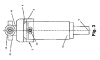
- FIG. 3 A cross-sectional view of the rotatable coupling (24) between sliding engagement member 6 and tool engaging member 8 is shown in FIG. 3 .
- the rotatable coupling between sliding engagement member 6 and tool engaging member 8 can allow tool engaging member 8 and other components of apparatus 2 to rotate to one or more other positions relative to axis Y.
- apparatus 2 is substantially parallel to the direction in which rotatable component 4 rotates, while apparatus 2A (shown in phantom) has been rotated to an angle ⁇ relative to axis Y.
- a machining tool 10, with an operative head 12 configured to treat the surface of rotating component 4, can be coupled to tool engaging member 8 of apparatus 2.
- a component of operative head 12 such as a grinding stone 14 can contact and machine a portion of rotatable component 4 as rotatable component 4 rotates.
- machining tool 10 can include a handle 16 for stabilizing and/or holding apparatus 2 in place while machining tool 10 treats rotatable component 4.
- Other components of apparatus 2 discussed herein can adjust the slidable engagement between apparatus 2 and rotatable component 4, and can allow apparatus 2 to treat rotatable component 4 according to methods discussed herein.
- Apparatus 2 can include sliding engagement member 6 projecting from apparatus 2.
- Embodiments of apparatus 2 can machine or otherwise treat rotatable component 4 ( FIG. 1 ), such as a turbine spacer or a turbine wheel, by allowing sliding engagement member 6 to slidably engage rotatable component 4 ( FIG. 1 ).
- Sliding engagement member 6 can be composed of any currently known or later developed material capable of slidably engaging and moving across the surface of rotatable component 4 ( FIG. 1 ) without treating rotatable component 4 ( FIG. 1 ).
- sliding engagement member 6 can be composed of a material with a low coefficient of friction with a particular material, and for example can be composed of a thermoplastic, a polymer-based material, or a resinous material.
- a portion of sliding engagement member 6 not used for slidably engaging rotatable component 4 ( FIG. 1 ) can be composed of another material, such as a metal.
- sliding engagement member 6 can include a projection 18 and a recess 20 configured to slidably engage particular portions of rotatable component 4 ( FIG. 1 ). Projection 18 and recess 20 are described in further detail herein with reference to FIG. 4 .
- Rotatable component 4 ( FIG. 1 ) can be treated by using operative head 12 of machining tool 10.
- Machining tool 10 can be coupled to tool engaging member 8 as shown by example in FIGS. 1 and 2 .
- operative head 12 of machining tool 10 can include a grinding stone 14 configured to grind rotating component 4 ( FIG. 1 ).
- sliding engagement member 6 slidably engages rotating component 4
- grinding stone 14 can also slidably engage and contact the surface of rotating component 4 ( FIG. 1 ).
- rotating component 4 rotates substantially along the direction of arrows A, B ( FIG. 1 )
- grinding stone 14 of apparatus 2 can slide across and grind rotatable component 4 to treat surfaces of rotatable component 4.
- grinding stone 14 can grind stress risers located on the surface of rotating component 4 ( FIG. 1 ) by moving grinding stone 14 and/or using friction between grinding stone 14 and rotating component 4 ( FIG. 1 ). Grinding stone 14 can be moved (e.g., rotated) with an electric motor or equivalent component contained within machining tool 10, e.g., inside of handle 16, as discussed in further detail herein with reference to FIG. 5 .
- grinding stone 14 can be composed of any currently known or later developed material capable of machining, grinding, or otherwise treating rotating component 4 ( FIG. 1 ).
- a turbine wheel or turbine spacer composed of a metal can be treated by a grinding stone composed of, e.g., an abrasive material such as aluminum oxide or silicon carbide.
- the size of grinding stone 14 can also be customized to suit particular applications. Where grinding stone 14 is substantially spherical, the diameter of grinding stone 14 can be selected to provide particular technical effects. Grinding stones 14 composed of a particular material or configured to have a certain size may provide a particular "aspect ratio" when treating the surface of a rotatable component.
- the term "aspect ratio" can generally refer to a length-to-width ratio, a length-to-depth ratio, or a width-to depth ratio of a portion of rotating component 4 ( FIG. 1 ).
- a particular aspect ratio may include width-to-depth where a treated surface forms part of a projecting or recessed portion of rotating component 4 ( FIG. 1 ).
- grinding stone 14 can provide a particular aspect ratio to the surface of rotating component 4 ( FIG. 1 ).
- operative head 12 of machining tool 10 can include a flapper 22 (shown in phantom in FIG. 2 ).
- Flapper 22 can repeatedly strike and introduce stress to the surface of rotatable component 4 ( FIG. 1 ) by a process known in the art as "peening.”
- flapper 22 can be configured to rotate about a particular axis.
- Flapper 22 can be actuated by any currently known or later developed means of imparting a mechanical force, such as a motor system positioned within handle 16.
- Flapper 22, when rotating can repeatedly strike the surface of rotating component 4 ( FIG. 1 ) to increase the stress of the material being treated.
- Flapper 22 can be composed of any currently known or later developed material used for flapper peening and capable of increasing a particular material's stress.
- flapper 22 can be composed of aluminum, copper, steel, or other types of currently known or later developed peening materials.
- Machining tool 10 can also include a handle 16 coupled to tool engaging member 8 for holding machining tool 10 in a particular location while treating rotatable component 4 ( FIG. 1 ).
- a user or a component of another apparatus can grip handle 16 to hold tool engaging member 8 at a particular position relative to the rotation of rotatable component 4 ( FIG. 1 ).
- a user of apparatus 2 can manually grip handle 16 to hold machining tool 10 in place, thereby allowing part of rotatable component 4 ( FIG. 1 ) to slide within or upon sliding engagement member 6.
- a user holding apparatus 2 with handle 16 can stabilize machining tool 10 as it contacts and treats the surface of rotatable component 4 ( FIG. 1 ).
- handle 16 can allow apparatus 2 to treat rotatable component 4 ( FIG. 1 ) in a manner similar to the "toolpost" component of a lathe.
- Machining tool 10 can include a motor system housed therein (e.g., within handle 16).
- the motor system of machining tool 10 can convert various types of power (e.g., electricity) into mechanical energy for actuating components coupled to operative head 12 of machining tool 10.
- the motor system can rotate grinding stone 14 and/or flapper 22 to increase friction between operative head 14 and rotatable component 4.
- the structure of apparatus 2 can be appropriately sized to house the components of any currently known or later developed motor system (e.g., an electric motor system).
- the motor system can be coupled to a rotatable shaft positioned between the motor system and grinding stone 14 or flapper 22. The motor system can rotate the rotatable shaft to move grinding stone 14 or flapper 22.
- FIG. 3 a front view of apparatus 2 is shown.
- Tool engaging member 8 can be rotatably coupled to sliding engagement member 6 through rotatable coupling 24, which can include any currently known or later developed type of coupling component such as a mechanically rotatable pin or joint.
- Rotatable coupling 24 can allow tool engaging member 8, machining tool 10, and handle 16 to rotate to any number of rotational positions relative to sliding engagement member 6, oriented in FIG. 3 along axis Y.
- mechanisms such as locks, latches, stops, and similar structures (not shown) can selectively prohibit rotatable coupling 24 from rotating away from a desired rotational position.
- Rotatable coupling 24 can allow apparatus 2 to be oriented in a plurality of rotational orientations as shown in FIG.
- apparatus 2A FIG. 1
- apparatus 2A FIG. 1
- a motor or pneumatic coupling located within machining tool 10 can actuate rotatable coupling 24.
- rotatable coupling 24 a user can customize the orientation and position of apparatus 2 while treating the surface of rotatable component 4 ( FIG. 1 )
- sliding engagement member 6 can include projection 18 for slidably engaging rotatable component 4.
- Other components coupled to apparatus 2 are omitted from FIG. 4 for clarity, but can be coupled to tool engaging member 8 at approximately the position of the phantom lines leading thereto.
- projection 18 can slidably engage a recessed portion 26 of rotating component 4.
- a contact area 28 between rotatable component 4 and recessed portion 26 includes projection 18 of sliding engagement member 6 slidably engaging recessed portion 26 between two projecting portions 30 of rotatable component 4.
- recess 20 can provide slidable engagement between apparatus 2 and rotatable component 4.
- Contact area 32 demonstrates by example that recess 20 can slidably engage a projecting portion 30 of rotatable component 4.
- projection 18 and recess 20 can provide more stable and versatile forms of sliding engagement between apparatus 2 and rotatable component 4 by increasing the size of the contact area with sliding engagement member 6.
- These forms of contact between apparatus 2 and rotatable component 4, through projection 18 or recess 20, can defend apparatus 2 (and machining tool 10) against vibrations and external forces as rotatable component 4 is treated.
- embodiments of apparatus 2 can include one or more projections 18 in conjunction with one or more recesses 20, or that the shape of projection 18 and/or recess 20 can vary between embodiments to accommodate different rotatable components 4.
- apparatus 2 can also include a supplemental fixture 34 coupled to sliding engagement member 6.
- Supplemental fixture 34 can project either a greater distance or a lesser distance from tool engaging member 8 than sliding engagement member 6.
- FIG. 6 shows supplemental fixture 34 as extending a lesser distance from tool engaging member 8 for the purposes of illustration.
- Supplemental fixture 34 can allow apparatus 2 to contact other portions of rotatable component 4 for increased stability.
- An example of how supplemental fixture 34 contacts a radially distal portion of rotatable component 4 is discussed herein with reference to FIG. 8 .
- Supplemental fixture 34 can be composed of substantially the same materials as in sliding engagement member 6, such as a resinous material or other material with a low coefficient of friction with the material composition of a rotatable component.
- supplemental fixture 34 can be a modular, removable component which can be exchanged with other supplemental fixtures 34 of varying lengths, in order to accommodate different types of rotatable components 4 ( FIGS. 1 , 4 , 5 ).
- some rotatable components may include alternating projecting and recessed surfaces, and supplemental fixture 34 can stabilize apparatus 2 by contacting a surface of rotating component 4 ( FIGS. 1 , 4 , 5 ) that is distinct from the surface being treated.
- FIGS. 7-8 a method of treating a rotatable component, such as a rotatable turbine component, is also illustrated.
- Methods of the present disclosure can include slidably engaging a rotatable component 4 with apparatus 2 to treat a surface 40 of rotatable component 4.
- Rotatable component 4 is shown by example in FIGS. 7-8 as being a rotatable turbine component (e.g., a turbine spacer or a turbine wheel). It is understood that rotatable component 4 can also be any other rotatable piece of machinery capable of being mechanically treated by processes such as grinding and peening.
- Rotatable component 4 can rotate substantially along the direction of arrows A and B (shown in phantom) in FIGS.
- Rotatable component 4 can rotate with the aid of a rotor 42.
- Embodiments of the method can include slidably engaging sliding engagement member 6 of apparatus 2 to rotatable component 4.
- Sliding engagement member 6, as discussed elsewhere herein, can be coupled to machining tool 10 through tool engaging member 8. Machining tool 10 can thus become substantially aligned with surface 40 of rotatable component 4 after sliding engagement member 6 slidably engages rotatable component 4.
- the terms "substantial alignment” or “substantially aligned” and their equivalents as used in the present disclosure refer to any alignment through which machining tool 10 and/or operative head 12 can contact rotatable component 4.
- Embodiments of the methods described herein can also include contacting surface 40 of rotatable component 4 using operative head 12 of machining tool 10.
- Operative head 12 can contact surface 40 after sliding engagement member 6 slidably engages rotatable component 4.
- Operative head 12 can be brought into contact with rotatable component 4 by slidably engaging rotatable component 4 with sliding engagement member 6.
- operative head 12 and sliding engagement member 6 both extend approximately the same length from apparatus 2
- operative head 12 can contact rotatable component 4 simultaneously with sliding engagement member 6 contacting rotatable component 4.
- a user can move operative head 12 of apparatus 2 relative to rotatable component 4 with supplemental components (not shown) within apparatus 2, such as a linear actuator, an extendable or rotatable member, etc. if desired.
- supplemental fixture 34 can contact a radially distal surface 44 (shown in phantom) relative to the surface being treated by machining tool 10, e.g., to increase stability when tool engaging member 8 has rotated relative to sliding engagement member 6.
- the contact between operative head 12 and surface 40 can provide a particular type of surface treatment as a user selectively rotates rotatable component 4 relative to operative head 12 of machining tool 10.
- operative head 12 includes grinding stone 14
- grinding stone 14 can treat surface 40 by sliding across and grinding the surface of rotatable component 4 as described herein.
- operative head 12 includes flapper 14
- operative head 12 can strike surface 40 by being rotated or actuated, causing flapper 14 to repeatedly contact surface 40 of rotating component 4.
- methods of the present disclosure can also include rotating tool engaging member 8 and operative head 12 relative to sliding engagement member 6.
- Rotatable coupling 24 ( FIG. 3 ) between sliding engagement member 6 and tool engaging member 8, discussed in detail elsewhere herein with respect to FIG. 3 , can permit apparatus 2 to rotate to several different positions relative to axis Y.
- Apparatus 2A and apparatus 2B represent two alternative rotational positions of apparatus 2 relative to axis Y.
- the different rotational positions shown herein e.g., apparatus 2A and apparatus 2B
- adjusting the rotational position of apparatus 2 can allow the electrical coupling between a motor system and operative head 14 to remain the same position.
- sliding engagement member 6 can contact and engage different surfaces of rotatable component 4.
- rotatable component 4 may include recessed portion 26 and projecting portion 30.
- Particular components of apparatus 2, such as projection 18, may be configured to engage recessed portion 26.
- other components or features such as recess 20 of apparatus 2 can engage projecting portion 30.
- embodiments of apparatus 2 can slidably engage different recessed and projecting portions 26, 30 as needed to treat different areas of rotatable component 4.
- apparatus 2B of FIG. 7 is shown as slidably engaging projecting portion 30, while apparatus 2C is shown as slidably engaging recessed portion 26.
- line C represents a zone of clearance between rotating component 4 and a turbine nozzle diaphragm 46.
- a small zone of clearance C between rotating component 4 and turbine nozzle diaphragm 46 may restrict the ability of apparatus 2 or components thereof to be positioned in a desired location, as suggested in FIG. 8 .
- Rotating tool engaging member 8 and operative head 12 relative to sliding engagement member 6 can allow operational head 12 to contact rotatable component 4 without other components of apparatus 2 being obstructed by turbine nozzle diaphragm 46 or other radially distal components of a larger assembly.
- handle 16 can also rotate relative to sliding engagement member 6 if desired, and can allow apparatus 2 to be affixed to a particular position relative to rotatable component 4.
- apparatus 2 can be "affixed" to a particular position by holding (e.g., by hand) handle 16 in place without turbine nozzle diaphragm 46 obstructing the position of apparatus 2.
- apparatus 2 can grind surface 40 of rotatable component 4.
- operative head 12 of machining tool 10 can include grinding stone 14.
- Grinding stone 14 can slidably engage and grind against surface 40 to remove blemishes and defects as rotatable component 4 rotates.
- a "stress riser" may arise from stresses acting on a component in a particular direction.
- a stress riser 48 may form on surface 40 after stress is imparted to rotatable component 4 by interference with turbine nozzle diaphragm 46.
- methods of the present disclosure can include coupling a particular type of grinding stone 14 to apparatus 2 in order to provide a particular aspect ratio to rotatable component 4.
- adjusting the size and material properties of grinding stone 14 can influence a resulting aspect ratio of rotatable component 4, such as a length-to-width ratio, length-to-height ratio, etc.
- apparatus 2 can peen surface 40 of rotatable component 4.
- Operative head 12 of machining tool 10 can include flapper 22. Flapper 22 can repeatedly strike surface 40 to introduce a desired amount of material stress.
- the method can include adjusting the speed at which flapper 22 strikes rotatable component 4, or changing the material composition of flapper 22.
- Methods of the present disclosure also include coupling other types of tools to operative head 12 to provide other currently known or later developed treatments.
- rotatable components such as turbine wheels and spacers can be treated in situ with a machining tool capable of uniformly treating stress risers and preserving the aspect ratio of a particular component.
- the apparatuses and methods disclosed herein can allow components to be machined and treated effectively while reducing the risk of further blemishes to a component.
- the mechanical-based solutions of the present disclosure can allow rotatable components to be treated in a short time and at a lower cost than electronic, computer-based, or system-based approaches to treating the surface of a rotatable component.
Landscapes
- Engineering & Computer Science (AREA)
- Mechanical Engineering (AREA)
- General Engineering & Computer Science (AREA)
- Grinding And Polishing Of Tertiary Curved Surfaces And Surfaces With Complex Shapes (AREA)
- Turning (AREA)
- Finish Polishing, Edge Sharpening, And Grinding By Specific Grinding Devices (AREA)
Applications Claiming Priority (1)
| Application Number | Priority Date | Filing Date | Title |
|---|---|---|---|
| US14/166,043 US9776298B2 (en) | 2014-01-28 | 2014-01-28 | Apparatus and method for treating rotatable component |
Publications (2)
| Publication Number | Publication Date |
|---|---|
| EP2898986A2 true EP2898986A2 (fr) | 2015-07-29 |
| EP2898986A3 EP2898986A3 (fr) | 2015-10-21 |
Family
ID=52396562
Family Applications (1)
| Application Number | Title | Priority Date | Filing Date |
|---|---|---|---|
| EP15152565.6A Withdrawn EP2898986A3 (fr) | 2014-01-28 | 2015-01-26 | Appareil et procédé pour traiter un composant rotatif |
Country Status (3)
| Country | Link |
|---|---|
| US (1) | US9776298B2 (fr) |
| EP (1) | EP2898986A3 (fr) |
| CN (1) | CN104802062A (fr) |
Families Citing this family (4)
| Publication number | Priority date | Publication date | Assignee | Title |
|---|---|---|---|---|
| FR3033724B1 (fr) * | 2015-03-17 | 2017-03-10 | Fives Fcb | Procede de reparation de la denture d'une couronne dentee |
| CN106271991A (zh) * | 2016-10-13 | 2017-01-04 | 中国石油化工股份有限公司 | 一种柱面零件精磨工装 |
| US11702953B2 (en) | 2020-02-03 | 2023-07-18 | General Electric Company | Engine inspection and maintenance tool |
| CN113414665B (zh) * | 2021-08-23 | 2021-11-09 | 江苏中科云控智能工业装备有限公司 | 基于数据分析自动更换清理工件的压铸件去毛刺装置 |
Family Cites Families (21)
| Publication number | Priority date | Publication date | Assignee | Title |
|---|---|---|---|---|
| US3893372A (en) * | 1973-08-06 | 1975-07-08 | Heinz Strakeljahn | Finishing tool |
| JPS5649716Y2 (fr) | 1976-11-15 | 1981-11-19 | ||
| US4477226A (en) | 1983-05-09 | 1984-10-16 | General Electric Company | Balance for rotating member |
| US4864777A (en) | 1987-04-13 | 1989-09-12 | General Electric Company | Method of automated grinding |
| FR2653361A1 (fr) | 1989-10-25 | 1991-04-26 | Snecma | Outillage de retouche d'aubes de rotor d'une turbomachine et procede de retouche utilisant cet outillage. |
| US5101557A (en) * | 1990-11-14 | 1992-04-07 | General Electric Company | Method for machining rotors |
| US5161291A (en) * | 1992-01-21 | 1992-11-10 | Westinghouse Electric Corp. | Adjustable machining apparatus for machining a cylindrical workpiece |
| DE4241767C1 (de) | 1992-12-11 | 1993-12-09 | Wolf Gmbh Richard | Instrument zum Bearbeiten der Oberfläche von Teilen in technischen Hohlräumen |
| DE19537812C1 (de) | 1995-10-11 | 1997-01-30 | Wolf Gmbh Richard | Instrument zum Bearbeiten der Oberfläche von Teilen in technischen Hohlräumen |
| US5704826A (en) | 1995-10-18 | 1998-01-06 | Danobat, S. Coop. Ltda. | Machine for grinding rotor blades provided with a multiwheel head |
| ES2199052B1 (es) | 2002-03-26 | 2005-02-01 | Danobat, S. Coop. | Maquina rectificadora de un rotor, con un cabezal rotatorio de dos muelas. |
| GB0212517D0 (en) | 2002-05-30 | 2002-07-10 | Balfour Beatty Plc | Rail grinding apparatus and method |
| US7118446B2 (en) | 2003-04-04 | 2006-10-10 | Strasbaugh, A California Corporation | Grinding apparatus and method |
| US6899593B1 (en) | 2003-11-18 | 2005-05-31 | Dieter Moeller | Grinding apparatus for blending defects on turbine blades and associated method of use |
| US7097539B2 (en) | 2003-11-18 | 2006-08-29 | Dieter Moeller | Rotary grinding apparatus for blending defects on turbine blades and associated method of use |
| US20110088921A1 (en) * | 2008-07-25 | 2011-04-21 | Sylvain Forgues | Pneumatic hand tool rotational speed control method and portable apparatus |
| US8196276B2 (en) | 2008-12-30 | 2012-06-12 | General Electric Company | Multi-functional rotary turning and positioning apparatus and method |
| CN102049718B (zh) * | 2010-11-03 | 2012-08-22 | 田野 | 通用型悬挂式汽车驱动桥平衡轴就车修复机 |
| US8813331B2 (en) * | 2011-03-29 | 2014-08-26 | General Electric Company | Process of preparing a turbine rotor wheel, a repair wheel for a turbine rotor wheel, and a turbine rotor wheel |
| US8402625B2 (en) * | 2011-08-30 | 2013-03-26 | General Electric Company | System and method for modifying a rotor |
| US8689441B2 (en) * | 2011-12-07 | 2014-04-08 | United Technologies Corporation | Method for machining a slot in a turbine engine rotor disk |
-
2014
- 2014-01-28 US US14/166,043 patent/US9776298B2/en not_active Expired - Fee Related
-
2015
- 2015-01-26 EP EP15152565.6A patent/EP2898986A3/fr not_active Withdrawn
- 2015-01-28 CN CN201510042522.2A patent/CN104802062A/zh active Pending
Non-Patent Citations (1)
| Title |
|---|
| None |
Also Published As
| Publication number | Publication date |
|---|---|
| US9776298B2 (en) | 2017-10-03 |
| CN104802062A (zh) | 2015-07-29 |
| EP2898986A3 (fr) | 2015-10-21 |
| US20150209929A1 (en) | 2015-07-30 |
Similar Documents
| Publication | Publication Date | Title |
|---|---|---|
| JP7370688B2 (ja) | 表面処理ツールおよび、ターボ機械の表面処理方法 | |
| JP6176797B2 (ja) | 現場用の翼成形工具 | |
| US6302625B1 (en) | Method and apparatus for refurbishing a gas turbine airfoil | |
| EP2898986A2 (fr) | Appareil et procédé pour traiter un composant rotatif | |
| US11506058B2 (en) | Turbomachine component with surface repair | |
| US20060059676A1 (en) | Fixture having integrated datum locators | |
| CN106764084A (zh) | 一种管道夹具 | |
| CA2615620A1 (fr) | Methode et appareillage augmentant la capacite des profils a la fatigue au moyen d'encoches | |
| US9713862B2 (en) | Turbomachine component displacement apparatus and method of use | |
| US10005139B2 (en) | Portable milling tool with method for turbomachine milling | |
| CN206929426U (zh) | 一种管道夹具 | |
| EP2732908A2 (fr) | Outil et procédé d'usinage d'une queue d'aronde | |
| CN103025482A (zh) | 加工具有开口的壳体的内侧的方法 | |
| CN207071821U (zh) | 一种机床主轴制动装置 | |
| CN107225472B (zh) | 一种叶片阻尼台的磨削装置 | |
| CN219945752U (zh) | 定位旋转装置和超精研磨设备 | |
| CN104039507A (zh) | 用于燃气涡轮发动机风扇叶片中的鸠尾榫的表面处理方法 | |
| CN204449367U (zh) | 一种车削轴心无孔的工件的车床工件夹具 | |
| CN210549288U (zh) | 一种转子汽封滚花刀 | |
| CN206855042U (zh) | 一种柱状物夹紧装置 | |
| CN104162814B (zh) | 开齿装置及开齿方法 | |
| JPH0760638A (ja) | 内面研削方法 | |
| US20110259149A1 (en) | Method and apparatus for a cutting tool | |
| KR19980042440U (ko) | 수동가스절단기의 노즐유도장치 |
Legal Events
| Date | Code | Title | Description |
|---|---|---|---|
| PUAI | Public reference made under article 153(3) epc to a published international application that has entered the european phase |
Free format text: ORIGINAL CODE: 0009012 |
|
| 17P | Request for examination filed |
Effective date: 20150126 |
|
| AK | Designated contracting states |
Kind code of ref document: A2 Designated state(s): AL AT BE BG CH CY CZ DE DK EE ES FI FR GB GR HR HU IE IS IT LI LT LU LV MC MK MT NL NO PL PT RO RS SE SI SK SM TR |
|
| AX | Request for extension of the european patent |
Extension state: BA ME |
|
| PUAL | Search report despatched |
Free format text: ORIGINAL CODE: 0009013 |
|
| AK | Designated contracting states |
Kind code of ref document: A3 Designated state(s): AL AT BE BG CH CY CZ DE DK EE ES FI FR GB GR HR HU IE IS IT LI LT LU LV MC MK MT NL NO PL PT RO RS SE SI SK SM TR |
|
| AX | Request for extension of the european patent |
Extension state: BA ME |
|
| RIC1 | Information provided on ipc code assigned before grant |
Ipc: B24B 23/08 20060101AFI20150917BHEP Ipc: F01D 5/00 20060101ALI20150917BHEP Ipc: B23P 6/00 20060101ALI20150917BHEP Ipc: B24B 23/02 20060101ALI20150917BHEP Ipc: B24B 39/00 20060101ALI20150917BHEP Ipc: F01D 25/28 20060101ALI20150917BHEP Ipc: B24B 27/00 20060101ALI20150917BHEP |
|
| 17P | Request for examination filed |
Effective date: 20160421 |
|
| RBV | Designated contracting states (corrected) |
Designated state(s): AL AT BE BG CH CY CZ DE DK EE ES FI FR GB GR HR HU IE IS IT LI LT LU LV MC MK MT NL NO PL PT RO RS SE SI SK SM TR |
|
| 17Q | First examination report despatched |
Effective date: 20181116 |
|
| STAA | Information on the status of an ep patent application or granted ep patent |
Free format text: STATUS: THE APPLICATION IS DEEMED TO BE WITHDRAWN |
|
| 18D | Application deemed to be withdrawn |
Effective date: 20190327 |