EP2899262B1 - Herstellung und verwendung eines neuronalen netzes sowie neuroneneinpflanzvorrichtung - Google Patents
Herstellung und verwendung eines neuronalen netzes sowie neuroneneinpflanzvorrichtung Download PDFInfo
- Publication number
- EP2899262B1 EP2899262B1 EP13838905.1A EP13838905A EP2899262B1 EP 2899262 B1 EP2899262 B1 EP 2899262B1 EP 13838905 A EP13838905 A EP 13838905A EP 2899262 B1 EP2899262 B1 EP 2899262B1
- Authority
- EP
- European Patent Office
- Prior art keywords
- neuron
- neurons
- cell
- suspension
- cell plating
- Prior art date
- Legal status (The legal status is an assumption and is not a legal conclusion. Google has not performed a legal analysis and makes no representation as to the accuracy of the status listed.)
- Active
Links
Images




Classifications
-
- G—PHYSICS
- G01—MEASURING; TESTING
- G01N—INVESTIGATING OR ANALYSING MATERIALS BY DETERMINING THEIR CHEMICAL OR PHYSICAL PROPERTIES
- G01N33/00—Investigating or analysing materials by specific methods not covered by groups G01N1/00 - G01N31/00
- G01N33/48—Biological material, e.g. blood, urine; Haemocytometers
- G01N33/483—Physical analysis of biological material
- G01N33/487—Physical analysis of biological material of liquid biological material
- G01N33/48707—Physical analysis of biological material of liquid biological material by electrical means
- G01N33/48728—Investigating individual cells, e.g. by patch clamp, voltage clamp
-
- C—CHEMISTRY; METALLURGY
- C12—BIOCHEMISTRY; BEER; SPIRITS; WINE; VINEGAR; MICROBIOLOGY; ENZYMOLOGY; MUTATION OR GENETIC ENGINEERING
- C12M—APPARATUS FOR ENZYMOLOGY OR MICROBIOLOGY; APPARATUS FOR CULTURING MICROORGANISMS FOR PRODUCING BIOMASS, FOR GROWING CELLS OR FOR OBTAINING FERMENTATION OR METABOLIC PRODUCTS, i.e. BIOREACTORS OR FERMENTERS
- C12M23/00—Constructional details, e.g. recesses, hinges
- C12M23/02—Form or structure of the vessel
- C12M23/04—Flat or tray type, drawers
-
- C—CHEMISTRY; METALLURGY
- C12—BIOCHEMISTRY; BEER; SPIRITS; WINE; VINEGAR; MICROBIOLOGY; ENZYMOLOGY; MUTATION OR GENETIC ENGINEERING
- C12M—APPARATUS FOR ENZYMOLOGY OR MICROBIOLOGY; APPARATUS FOR CULTURING MICROORGANISMS FOR PRODUCING BIOMASS, FOR GROWING CELLS OR FOR OBTAINING FERMENTATION OR METABOLIC PRODUCTS, i.e. BIOREACTORS OR FERMENTERS
- C12M23/00—Constructional details, e.g. recesses, hinges
- C12M23/02—Form or structure of the vessel
- C12M23/12—Well or multiwell plates
-
- C—CHEMISTRY; METALLURGY
- C12—BIOCHEMISTRY; BEER; SPIRITS; WINE; VINEGAR; MICROBIOLOGY; ENZYMOLOGY; MUTATION OR GENETIC ENGINEERING
- C12M—APPARATUS FOR ENZYMOLOGY OR MICROBIOLOGY; APPARATUS FOR CULTURING MICROORGANISMS FOR PRODUCING BIOMASS, FOR GROWING CELLS OR FOR OBTAINING FERMENTATION OR METABOLIC PRODUCTS, i.e. BIOREACTORS OR FERMENTERS
- C12M23/00—Constructional details, e.g. recesses, hinges
- C12M23/38—Caps; Covers; Plugs; Pouring means
-
- C—CHEMISTRY; METALLURGY
- C12—BIOCHEMISTRY; BEER; SPIRITS; WINE; VINEGAR; MICROBIOLOGY; ENZYMOLOGY; MUTATION OR GENETIC ENGINEERING
- C12M—APPARATUS FOR ENZYMOLOGY OR MICROBIOLOGY; APPARATUS FOR CULTURING MICROORGANISMS FOR PRODUCING BIOMASS, FOR GROWING CELLS OR FOR OBTAINING FERMENTATION OR METABOLIC PRODUCTS, i.e. BIOREACTORS OR FERMENTERS
- C12M25/00—Means for supporting, enclosing or fixing the microorganisms, e.g. immunocoatings
- C12M25/06—Plates; Walls; Drawers; Multilayer plates
-
- C—CHEMISTRY; METALLURGY
- C12—BIOCHEMISTRY; BEER; SPIRITS; WINE; VINEGAR; MICROBIOLOGY; ENZYMOLOGY; MUTATION OR GENETIC ENGINEERING
- C12M—APPARATUS FOR ENZYMOLOGY OR MICROBIOLOGY; APPARATUS FOR CULTURING MICROORGANISMS FOR PRODUCING BIOMASS, FOR GROWING CELLS OR FOR OBTAINING FERMENTATION OR METABOLIC PRODUCTS, i.e. BIOREACTORS OR FERMENTERS
- C12M33/00—Means for introduction, transport, positioning, extraction, harvesting, peeling or sampling of biological material in or from the apparatus
-
- C—CHEMISTRY; METALLURGY
- C12—BIOCHEMISTRY; BEER; SPIRITS; WINE; VINEGAR; MICROBIOLOGY; ENZYMOLOGY; MUTATION OR GENETIC ENGINEERING
- C12M—APPARATUS FOR ENZYMOLOGY OR MICROBIOLOGY; APPARATUS FOR CULTURING MICROORGANISMS FOR PRODUCING BIOMASS, FOR GROWING CELLS OR FOR OBTAINING FERMENTATION OR METABOLIC PRODUCTS, i.e. BIOREACTORS OR FERMENTERS
- C12M33/00—Means for introduction, transport, positioning, extraction, harvesting, peeling or sampling of biological material in or from the apparatus
- C12M33/04—Means for introduction, transport, positioning, extraction, harvesting, peeling or sampling of biological material in or from the apparatus by injection or suction, e.g. using pipettes, syringes, needles
-
- C—CHEMISTRY; METALLURGY
- C12—BIOCHEMISTRY; BEER; SPIRITS; WINE; VINEGAR; MICROBIOLOGY; ENZYMOLOGY; MUTATION OR GENETIC ENGINEERING
- C12M—APPARATUS FOR ENZYMOLOGY OR MICROBIOLOGY; APPARATUS FOR CULTURING MICROORGANISMS FOR PRODUCING BIOMASS, FOR GROWING CELLS OR FOR OBTAINING FERMENTATION OR METABOLIC PRODUCTS, i.e. BIOREACTORS OR FERMENTERS
- C12M35/00—Means for application of stress for stimulating the growth of microorganisms or the generation of fermentation or metabolic products; Means for electroporation or cell fusion
- C12M35/02—Electrical or electromagnetic means, e.g. for electroporation or for cell fusion
-
- C—CHEMISTRY; METALLURGY
- C12—BIOCHEMISTRY; BEER; SPIRITS; WINE; VINEGAR; MICROBIOLOGY; ENZYMOLOGY; MUTATION OR GENETIC ENGINEERING
- C12N—MICROORGANISMS OR ENZYMES; COMPOSITIONS THEREOF; PROPAGATING, PRESERVING, OR MAINTAINING MICROORGANISMS; MUTATION OR GENETIC ENGINEERING; CULTURE MEDIA
- C12N5/00—Undifferentiated human, animal or plant cells, e.g. cell lines; Tissues; Cultivation or maintenance thereof; Culture media therefor
- C12N5/06—Animal cells or tissues; Human cells or tissues
- C12N5/0602—Vertebrate cells
- C12N5/0618—Cells of the nervous system
- C12N5/0619—Neurons
Definitions
- the present invention relates to the formation and use of a neuron network, and to a neuron seeding device. More specifically, the invention relates to a culturing device for formation of a neuron network, that through culturing forms a neuron network via synaptic junctions between axons of neurons and dendrites of other neurons, and to a method of using the device to form such a neuron network. In addition, the invention relates to high throughput screening technology, planar patch-clamp technology and neuron imaging technology using such a neuron network.
- the invention relates to a neuron seeding device for efficient seeding of neurons in a plurality of selected regions (cell plating sections) of a culturing device for formation of a neuron network or a planar patch-clamp device utilizing the culturing device.
- the term “neuron” includes, firstly, various types of neurons such as central neurons and peripheral neurons. The neurons are preferably in a state yet without axonal or dendritic processes.
- the term “neuron” also encompasses, secondly, cells capable of differentiating into neurons, such as iPS cells and ES cells, and more preferably neural stem cells that are en route to differentiation to neurons from iPS cells or ES cells.
- the term “neuron” includes, thirdly, cells having a property of forming an intracellular network, and cells capable of differentiating into cells having a property of forming an intracellular network.
- neuroneuronal cell body refers to the cell body section excluding the processes such as the axons and dendrites of the neuron.
- selected region and “cell plating section” refer to the region on a plate in which there are set the neurons which are to be the center of neuron network formation, or the target of current/voltage application for ion channel current measurement or various types of imaging
- selected cells refers to the neurons in the selected region (cell plating section).
- the prior art has proposed keeping neurons in culture medium (particularly liquid medium) to construct neuron networks in vitro, with the neurons in a live state.
- NPL 1 for example, there is described formation of a region surrounded by a plurality of protrusions on a Si plate bearing a transistor, as shown in Fig. 2 , placement of a large ganglion, as an aggregate of peripheral neurons, of L. stagnalis , therein and detection of variations in the potential of the neurons.
- NPL 2 discloses a neurochip wherein a plurality of roughly circular enclosures known as "cages" (approximately 9 ⁇ m height) such as shown in Fig. 3 , are formed on a plate, neurons are situated in the space at the center section of each cage, and the axons of neurons are caused to elongate toward neurons in adjacent cages, through several tunnels provided in the cage.
- ages approximately 9 ⁇ m height
- Fig. 1 a problem has been encountered when using a structure such as shown in Fig. 1 , for example, wherein circular recesses (5 ⁇ m depth) connected by narrow grooves to guide elongation of axons on the plate are provided and neurons are placed in the recesses, in that while this restricts migration of the neurons, most of the neurons situated in the recesses die after 2 to 3 days, making it impossible to form a satisfactory neuron network.
- NPL 1 places nerve tissue in a region surrounded by a plurality of protrusions, but the object is the giant ganglion of L. stagnalis that does not have active mobility. Also, the gaps between the plurality of protrusions easily exceed 50 ⁇ m, and it is completely impossible to restrict ordinary neuronal migration. Furthermore, the structure is on a transistor plate with numerous irregularities having heights exceeding 5 ⁇ m.
- NPL 2 the neurons in each cage are mutually surrounded by irregular structures known as "cages", each having a height of approximately 9 ⁇ m.
- the cage is provided with tunnels having a width of 10 ⁇ m and a height of 1 ⁇ m for axon elongation, it is difficult for neurons in the cages to mutually recognize adjacent neurons through such narrow tunnels. Therefore, NPLs 1 and 2 do not solve the problems alluded to above, nor do they suggest a solution means.
- Methods of forming neuron networks based on application of high throughput screening are important techniques in terms of how neuron seeding is accomplished. For example, when a network is formed having 100 measurement points, with 25 points of cell plating sections surrounding each of the measurement points, this requires seeding of a prescribed number of neuronal cell bodies in a short period of time, usually within 1 hour, at a total of 2500 cell plating sections.
- NPLs 1 and 2 do not disclose a neuron seeding system for efficient seeding of neurons at multiple cell plating sections. Also, in a method wherein a tool such as an ordinary pipette or a pipette with a metrological function, or a microinjector, is used to seed neurons in individual cell plating sections by manual operation, firstly, it is difficult to accomplish proper seeding in fine cell plating sections and secondly, the seeding efficiency is extremely inferior, and therefore such a method is non-realistic.
- a tool such as an ordinary pipette or a pipette with a metrological function, or a microinjector
- the device must be constructed in such a manner as to not inhibit formation of a neuron network in the planar direction of the apparatus plate.
- the construction of the first invention designed to solve the aforementioned problems is a culturing device for formation of a neuron network, wherein cell plating sections surrounded by a plurality of protrusions are formed on a flat plate that can be filled with a cell culture medium, the cell plating section satisfying the following conditions (1) to (3).
- one to several neuronal cell bodies means at least one and no more than 10, and preferably at least one and no more than 5 neuronal cell bodies.
- the construction of the second invention designed to solve the aforementioned problems is a culturing device for formation of a neuron network, wherein the culturing device of the first invention corresponds to any one of the following (1) to (3).
- Fig. 4(a) shows an essential portion plan view of the plate of a culturing device according to (1) of the second invention, wherein the neuron 11 shown at the center (actually one to several neurons) is situated in a selected region that is the cell plating section 13 surrounded by multiple (6) cylindrical protrusions 12, with the surrounding neurons 11 simply being seeded on the plate. A network is also formed by these neurons 11.
- Fig. 4(b) shows an essential portion plan view of the plate of a culturing device according to (2) of the second invention, wherein multiple cell plating sections 13 are formed mutually separated by gaps on the plate in an appropriate manner, a neuron 11 (actually one or more neurons) is situated in each of the cell plating sections 13, and one of the cell plating sections 13 is used as the selected region. A network is also formed by these neurons 11.
- a plurality of or many neuron network units such as shown in Fig. 4(a) or Fig. 4(b) are dispersed at appropriate locations on the plate, so that they are mutually independent network units.
- the construction of the third invention designed to solve the aforementioned problems is a culturing device for formation of a neuron network according to the first invention or second invention, the culturing device for formation of a neuron network being a planar patch-clamp device designed for a neuron network, wherein:
- the construction of the fourth invention designed to solve the aforementioned problems is a culturing device for formation of a neuron network, wherein in a planar patch-clamp device according to the third invention, the electrode sections on the first surface side and second surface side comprise the following constituents (a) to (c).
- the construction of the fifth invention designed to solve the aforementioned problems is a culturing device for formation of a neuron network according to any one of the first invention to fourth invention, wherein the culturing device for formation of a neuron network is used for a purpose according to any one of the following (A) to (C).
- the construction of the sixth invention designed to solve the aforementioned problems is a culturing device for formation of a neuron network according to the fifth invention wherein, when the culturing device for formation of a neuron network is to be used for imaging analysis according to (B), the culturing device comprises one or more of the following constituents (D) to (F).
- the construction of the seventh invention designed to solve the aforementioned problems is a method of forming a neuron network under culturing for any desired research purpose, by means of a culturing device for formation of a neuron network according to any one of the first invention to sixth invention.
- the method of forming a neuron network comprises:
- the construction of the eighth invention designed to solve the aforementioned problems is a method of forming a neuron network under according to the seventh invention, wherein during seeding of the neurons in step (1), glial cells are also seeded at sections other than the cell plating sections.
- the construction of the ninth invention designed to solve the aforementioned problems is a neuron seeding device for seeding of neurons in multiple cell plating sections each surrounded by a plurality of protrusions on the apparatus plate, wherein the neuron seeding device is set on the flat apparatus plate that can be filled with cell culture medium in a culturing device for formation of a neuron network or in a planar patch-clamp device utilizing such a culturing device, wherein a board-shaped device body that can be set on the apparatus plate has a size covering the multiple cell plating sections and the flat bottom of the device body is in contact with the apexes of the plurality of protrusions at the multiple cell plating sections, the device body is provided with (1) a suspension supply port for externally supplying of a neuron suspension having neurons suspended at a fixed density, (2) a plurality of fine suspension flow channels extending in a branched manner from the suspension supply port, inside the device body, and (3) a suspension injection port for injecting of neuron suspension into each cell
- the construction of the tenth invention designed to solve the aforementioned problems is a neuron seeding device according to the ninth invention, wherein the plurality of suspension flow channels are set to have substantially the same lengths, and the design is such that when the neuron seeding device is placed on the apparatus plate of the culturing device for formation of a neuron network or the planar patch-clamp device, the individual suspension injection ports are located to precisely correspond with the individual cell plating sections.
- the construction of the eleventh invention designed to solve the aforementioned problems is a neuron seeding device according to the ninth invention or tenth invention, wherein the board-shaped device body comprises an upper board provided with the suspension supply ports and a lower board provided with the suspension injection ports, joined in a closely bonded state, with grooves composing the suspension flow channels being formed on at least one of the bonding surfaces of the upper board and lower board.
- the construction of the twelfth invention designed to solve the aforementioned problems is a neuron seeding device according to any one of the ninth invention to eleventh invention, wherein the culturing device for formation of a neuron network is a culturing device for formation of a neuron network according to the first invention, and/or the planar patch-clamp device according to any one of the ninth invention to eleventh invention is a planar patch-clamp device according to the third invention.
- the construction of the thirteenth invention designed to solve the aforementioned problems is a neuron seeding device according to any one of the ninth invention to twelfth invention, wherein the device body further comprises second suspension flow channels for injection of the neuron suspension into regions other than the cell plating sections of the apparatus plate of the culturing device for formation of a neuron network or the planar patch-clamp device.
- the culturing device for formation of a neuron network of the first invention comprises cell plating sections surrounded by a plurality of protrusions, formed on a flat plate, and therefore the neurons placed therein have their random movement restricted by the plurality of protrusions. Random movement of the neurons is therefore restricted.
- the insides and outsides of the cell plating sections are on the same flat plate surface, with no level differences (irregularities) between them.
- wide gaps are set between the plurality of protrusions of the cell plating sections, though not wide enough to allow passage of the neuronal cell bodies, and the gap sections are spaces that are open above, instead of narrow tunnel spaces such as disclosed in NPL 2. Consequently, the neurons situated in the cell plating sections can easily recognize adjacent neurons with which they are to form a network, and it is possible to create a satisfactory neuron network based on formation of synaptic junctions between axons and dendrites utilizing the gaps between the protrusions.
- the inner diameters of the cell plating sections defined by the plurality of protrusions have sizes allowing accommodation of one to several neuronal cell bodies, one to several neuronal cell bodies are situated and plated in each cell plating section.
- neurons especially iPS cells and the like
- neurons can survive more stably for longer periods when in a state of aggregates of several cells (clusters).
- signal transfer between neurons will be simplified and analysis of the network function will be easier.
- one to several neuronal cell bodies are situated and plated in each cell plating section, thereby creating a satisfactory balance between both of the aforementioned requirements.
- neurons When a culturing device for formation of a neuron network according to the first invention is used, neurons can survive for long periods of 4 weeks or longer, and an active neuron network can be maintained.
- an extracellular matrix exhibiting adhesive force for neurons is coated onto the plate surface composing the bottom of the cell plating section, and/or fine through-holes for suction of cell culture medium by an aspirator provided below the plate are provided with hole diameters that do not allow passage of neurons.
- an aspirator provided below the plate are provided with hole diameters that do not allow passage of neurons.
- a culturing device for formation of a neuron network used to form a neuron network as shown in Fig. 4(a) or a neuron network as shown in Fig. 4(b) , and a plurality or many of such neuron network units may be formed on the plate.
- a culturing device for high-throughput analysis of a neuron network is provided.
- a planar patch-clamp device allows multipoint measurement by constructing a plurality of patch-clamp devices on a solid plate having electrical insulating properties, such as a silicon chip, and it has fine through-holes for measurement of ion channel current at each of the cell placement locations of each patch-clamp device.
- the "fine through-holes for suction of cell culture medium by an aspirator provided below the plate", as specified by (3)(b) of the first invention are used as fine through-holes for measurement of the ion channel current.
- a substance such as adenosine 5-[ ⁇ -thio]diphosphate, uridine 5-triphosphate trisodium salt hydrate or EGF, which has a neuron-attracting effect, may be mixed with the cell culture medium on the second surface side to attract neurons into the cell culture medium on the second surface side, thereby guiding the neurons to the fine through-holes to more reliably keep the neurons in the fine through-holes during the culturing period.
- a conventional planar patch-clamp device does not have a cell culturing function, a problem has been encountered in that it has not been applicable for cells that require culturing, such as neurons.
- the device because the lifetime of cells to be measured is as short as 1 hour or even 30 minutes or less under non-culturing conditions, the device only has limited application for innovative drug screening, and it has been difficult to apply for functional analysis of cells wherein a pipette patch clamp is employed.
- a culturing device for formation of a neuron network according to the first invention or the second invention is used as a planar patch-clamp device for a neuron network, so that a planar patch-clamp device can be provided that is designed for a neuron network of neurons that require culturing, and that results in a notably extended lifetime for the neurons to be measured. Furthermore, by using a culturing device for formation of a neuron network specified by (3) of the second invention, it is possible to accomplish high-throughput screening in a neuron network.
- the planar patch-clamp device electrode used is an electrode having a precious metal chloride (NmCl) layer (for example, an AgCl layer) formed on the surface layer section of the precious metal Nm (for example, silver Ag)
- NmCl precious metal chloride
- fluctuations in the applied membrane potential are mainly due to fluctuations in the interface potential between the surface of the AgCl/Ag electrode and the solution surrounding it, or fluctuations in the liquid-liquid interface potential.
- an AgCl/Ag electrode in an electrode solution which is a saturated solution of AgCl and an alkali metal chloride (for example, KCl) (the KCl concentration being about 100-150 millimoles) in the electrode receptacle of the electrode section, and contacting these with a conducting liquid such as a cell culture solution (the KCl concentration being about a few millimoles) through the receptacle wall formed of an inorganic porous material, as according to the fourth invention, the interior and exterior of the electrode receptacle are brought to an electrically conductive state.
- an electrode solution which is a saturated solution of AgCl and an alkali metal chloride (for example, KCl) (the KCl concentration being about 100-150 millimoles) in the electrode receptacle of the electrode section, and contacting these with a conducting liquid such as a cell culture solution (the KCl concentration being about a few millimoles) through the receptacle wall formed of an inorganic porous
- a culturing device for formation of a neuron network may be used for (A) measurement and analysis of the neuronal ion channel current in the neuron network, (B) imaging analysis that includes at least Ca imaging analysis, imaging analysis with synaptophysin or synapsin labeling as synaptic site markers, imaging analysis with MAP2 as a dendrite marker, and imaging analysis with FM1-43 or FM4-64 which labels endosomes or exosomes, or (C) a high throughput screening system for a neuron network.
- a culturing device for formation of a neuron network according to the fifth invention is used for imaging analysis according to (C), because it further comprises one or more elements from among (D) a photodetector, (E) an irradiating device and (F) an optical focusing system
- effects are obtained such as, firstly, that it is possible to accomplish analysis without inhibiting the neuron network function, since measurement can usually be carried out in a noncontact and non-destructive manner, secondly, that the optical measurement allows analysis at high speed, and thirdly, that it is possible to exactly excite a single neuron and precisely analyze it with the (F) optical focusing system, even when multiple neurons (cell clusters) are situated in the cell plating section.
- steps (1) to (3) mentioned above are carried out using a culturing device for formation of a neuron network according to any one of the first invention to sixth invention.
- the extracellular matrix-forming substance in each cell plating section, or suction of cell culture medium through the fine through-holes at the bottom of the cell plating section allows one to several neuronal cell bodies to be reliably placed and plated in the cell plating section. More specifically, cell bodies may be placed and plated on the fine through-holes of the cell plating section.
- each cell plating section roughly corresponds to a size allowing accommodation of one to several neuronal cell bodies, one to several neurons are reliably situated in each cell plating section. These neurons have their random movement restricted by the plurality of protrusions forming the cell plating section. Furthermore, since the inside and outside of the cell plating section are on the same flat plate surface and there is no level difference (irregularities) between them, the neurons disposed on the cell plating section can easily recognize adjacent neurons that are to form the network, through the gaps between the plurality of protrusions composing the cell plating section. Thus, the neurons can be kept in an actively live state while forming a satisfactory neuron network based on formation of synaptic junctions between axons and dendrites utilizing the gaps between the protrusions.
- the seventh invention allows formation of a satisfactory neuron network between individual neuron clusters of several neurons placed and plated in each cell plating section.
- the neurons form a stable network with approximately 100% probability, and culturing can be continued for prolonged periods of 4 weeks and longer. It is therefore a highly useful technique for producing a high throughput screening element for a neuron network.
- the neurons when neurons are seeded by step (1) of the seventh invention, the neurons are seeded both inside the selected regions and outside the selected regions while glial cells are seeded outside the selected regions.
- glial cells are present near the synapse and in contact with the neurons, as known from publications such as " F.W. Pfrieger et al., Science 277(1997) 1684-1687 ", this increases maturation of the neuron network and allows construction of a neuron network with a more homogeneous spatio-temporal function.
- a neuron seeding device for efficient seeding of neurons in multiple cell plating sections of a culturing device for formation of a neuron network or a planar patch-clamp device utilizing the culturing device.
- the board-shaped device body of the device comprises (1) a suspension supply port for external supply of a neuron suspension, (2) a plurality of fine suspension flow channels extending in a branched fashion from the suspension supply port, and (3) a suspension injection port opened at the bottom of the device body at the end of each suspension flow channel.
- the method of supplying the neuron suspension to the suspension supply port is not restricted, but in consideration of fluid friction resistance in the multiple fine suspension flow channels, supply of the neuron suspension is preferably carried out with a tool or device allowing injection of liquid into the suspension supply port (for example, an injector or microsyringe, or a small pump-type injector), under a pressurized state.
- a tool or device allowing injection of liquid into the suspension supply port (for example, an injector or microsyringe, or a small pump-type injector), under a pressurized state.
- a connecting pipe with a tapered tip end may be fitted at the injection port of the liquid inject tool/device, allowing the tapered tip end to be inserted into the suspension supply port.
- the tapered section of the tip end of the connecting pipe may be provided by fitting a small stainless steel nozzle-shaped pipe member, for example.
- the neurons injected into the cell plating section have their flow out of the cell plating section halted by the plurality of protrusions of the cell plating section, and therefore stop within the cell plating section.
- the suspension medium flows out between the plurality of protrusions of the cell plating section. Consequently, the neurons are seeded into the cell plating section in an intact state with minimal stress. Furthermore, since seeding of the neurons is accomplished all at once, seeding of the neurons in the multiple cell plating sections on the apparatus plate is completed essentially simultaneously, and within a very short period of time (about several tens of seconds).
- the neuron seeding device is setup in the culturing device for formation of a neuron network or the planar patch-clamp device, on a flat apparatus plate that can be filled with cell culture medium.
- the construction is such that the neuron suspension is injected from above the cell plating section. Consequently, there is no hindrance to formation of a neuron network in the planar direction on the apparatus plate.
- the neuron seeding device While it is possible to anchor the neuron seeding device on the apparatus plate of the culturing device for formation of a neuron network or the planar patch-clamp device, if it is set in a detachable manner and removed after seeding of the neurons, it will not impede supply of oxygen or carbon dioxide gas during culturing of the seeded neurons and will not interfere with measurement of the network or introduction of chemical solution from above.
- the multiple suspension flow channels are set to substantially the same length, and therefore seeding of the neurons in the multiple cell plating sections on the apparatus plate is completed accurately and simultaneously.
- the liquid volume of the neuron suspension supplied from the suspension supply port is controlled after adjusting the dispersion density of the neurons of the neuron suspension on the nodes, an effect is obtained whereby the injection rate of neuron suspension into the cell plating section (and therefore the number of neurons seeded) can be controlled in essentially a precise manner, and whereby the number of neurons seeded in the multiple cell plating sections can be controlled to be essentially equal.
- These effects may be considered to be major effects for forming a neuron network that is presumably to be used for high throughput screening.
- the design is such that when the neuron seeding device is placed on the apparatus plate of the culturing device for formation of a neuron network or the planar patch-clamp device, the individual suspension injection ports are located to precisely correspond with the individual cell plating sections, seeding of neurons in the multiple cell plating sections is accomplished in a precise manner.
- the labeling marks for positioning of both may be provided on either or both the apparatus plate and device body, and it is particularly effective when the device body is made of a highly transparent material since this will allow such labeling marks to be visible through it.
- the board-shaped device body has an upper board provided with a suspension supply port and a lower board provided with a suspension injection port, with grooves forming suspension flow channels in at least one of the bonding surfaces of the boards, thus facilitating the working steps for forming numerous fine, curved suspension flow channels inside the device body.
- the method of working to form the suspension flow channels is not limited to the one described here.
- neuron seeding devices wherein the culturing device for formation of a neuron network is one according to the first invention, and/or the planar patch-clamp device is one according to the third invention.
- the device body of the thirteenth invention further comprises second suspension flow channels for injection of a neuron suspension into regions other than the cell plating sections of the apparatus plate. Since it is thus possible to seed neurons by appropriately injecting a neuron suspension into regions other than the cell plating sections of the apparatus plate, the neuron network can be formed in a particularly satisfactory manner.
- the technical field of the invention is the technical field of forming a neuron network while culturing neurons in a stable condition. Also, it is the technical field of measuring ion channel current on cell surfaces. It is additionally the field of stimulating cells by injecting current or applying voltage. It is yet further the field of high throughput screening technology of the type involving measurement of ion channel current or stimulating cells by injecting current or applying voltage. It is still yet further the field of Ca imaging or various other types of imaging techniques designed for neurons or neuron networks.
- Neurons comprise cell bodies that are the main bodies of the cells, and axons and dendrites that elongated from the cell bodies.
- neurons such as central neurons or peripheral neurons, and most preferably neurons in a state before processes such as axons and dendrites have developed.
- cells capable of differentiating into neurons such as iPS cells and ES cells, and more preferably neural stem cells that are en route to differentiation to neurons from iPS cells or ES cells.
- cells having a property of forming an intracellular network and cells capable of differentiating into cells having a property of forming an intracellular network.
- the neurons are preferably animal neurons, and most preferably neurons of mammals, which include humans.
- the sizes of the cell bodies of the neurons will usually be less than 20 ⁇ m, and more specifically are about 3 to 18 ⁇ m.
- the neuron network has as its basic structural unit a pair of neurons, namely a trigger cell that emits a signal and a follower cell that receives it.
- the present inventors have found that when the difference in the heights on the surface on which the trigger cells and follower cells are present is about the size of the cells, the cell death rate increases.
- cell plating sections are formed by a plurality of protrusions, on a flat plate that can be filled with a cell culture medium (most preferably a liquid medium).
- the "flat plate that can be filled with a cell culture medium” has the construction described for the planar patch-clamp device described below, for example.
- the cell plating sections are a plurality or many set on the plate according to the structure of (1) to (3) of the second invention.
- the base unit in the neuron network is a pair of neurons consisting of a trigger cell and a follower cell, when the structure is such that spontaneous firing of a neuron is the trigger and ion channel current is received by the follower cell, a cell plating section as the selected region can operate as a functional analysis element even at a single location.
- the mutual gaps between the cell plating sections as the selected regions will differ depending on the type of neuron network and cannot be specified for all cases, but they may be about 50 to 500 ⁇ m, for example.
- the shapes of the plurality of protrusions forming the cell plating section are not restricted, but are preferably fence-shaped or post-shaped, for example.
- the heights of the protrusions are also not restricted, but they are generally preferred to be heights of about 10 ⁇ m to effectively restrict random movement of the neurons, and for example, for mouse cerebral cortex or hippocampal neurons they are preferably heights of about 5 to 10 ⁇ m.
- the cell plating section satisfies the following conditions (1) to (3).
- the (a) extracellular matrix-forming substance is one that exhibits adhesive force for neurons in order to plate the neurons at the bottom of the cell plating section
- the constituent materials include polylysine, collagen (type I, type I and type IV), fibronectin, laminin, proteoglycan, (versican, decholin and the like), proteoglycan (aggrecan), link proteins, entactin, tenascin, proteoglycans [chondroitin sulfate proteoglycan, heparan sulfate proteoglycan (perlecan and the like), keratan sulfate proteoglycan and dermatan sulfate proteoglycan], hyaluronic acid (a type of glycosaminoglycan), elastin, fibrin, gelatin, Matrigel, and the like.
- the fine through-holes for suction of cell culture medium specified by (b) allow suctioning of cell culture medium with an aspirator on the lower side of the plate, thereby plating the one to several neurons situated in the cell plating section onto the bottom of the cell plating section, the hole diameters being of a size that the neurons do not pass through, such as about 1 to 3 ⁇ m.
- One example of effective use of the culturing device for formation of a neuron network is as a planar patch-clamp device for a neuron network.
- membrane proteins are arranged on the surface of cells composing an organism, and binding of chemical substances (signal transfer substances such as ligands) to specific sites on the cell surface or electrical or optical stimulation (gate trigger) opens and closes the channels serving as openings for membrane proteins, to control transport of ions and chemical substances between the outside and inside of the cell membrane.
- the ion channels that carry out this control are membrane proteins that are important for biological signal transfer, and measurement of electrical changes in channel proteins, i.e. ion channel current, is one of the goals for functional measurement and development of function-related chemicals.
- a planar patch-clamp is a flat plate-like patch-clamp device that allows multipoint measurement of cell ion channel current by constructing a plurality of patch-clamp devices on a solid plate such as a silicon chip, and it has fine through-holes for measurement of ion channel current at each of the cell placement locations of each patch-clamp device.
- a common conventional planar patch-clamp device does not have a cell culturing function, a problem has been encountered in that it has not been applicable for cells that require culturing, such as neurons.
- the device because the lifetime of cells to be measured is as short as 1 hour or even 30 minutes or less under non-culturing conditions, the device only has limited application for innovative drug screening, and it has been difficult to apply it for functional analysis of cells wherein a pipette patch clamp is employed.
- a planar patch-clamp device of the invention also has a neuron-culturing function, unlike a planar patch-clamp device with a common construction as described above, and it allows effective minimization of noise current during ion channel current measurement and stable positioning of cells. That is, the characteristic construction of the device is such that cell-anchoring force is applied to the opening for plating of the neuron at the fine through-holes provided on the plate, and a liquid pool section capable of current flow to an electrode is provided on the surfaces on both sides of the through-holes in the plate, the liquid pool section being fillable with a conducting liquid (for example, a cell culture solution).
- a conducting liquid for example, a cell culture solution
- the culturing device for formation of a neuron network in the planar patch-clamp device of the invention is constructed in a manner according to the following (1) to (3).
- fine through-holes are provided allowing communication between the first surface side (the surface side on which the cells are placed) and the second surface side, which are both surfaces of the plate with electrical insulating properties.
- the plate with electrical insulating properties is preferably a plate made of glass, ceramic, plastic or the like.
- a silicon plate When a silicon plate is to be used, a preferred example is a silicon plate (SOI plate) having a laminated structure with a silicon layer on the first surface side, a silicon oxide layer in the middle and a silicon layer on the second surface side. Since a silicon plate having such a layered structure has a very highly insulating interlayer present between two silicon layers, it is possible to establish a high resistance state during ion channel closure of the cell being measured, and to reduce background noise.
- the number of through-holes in the plate is not particularly restricted, but it is preferably several to many, and for example, two to several dozen, or more.
- the inner diameters of the fine through-holes are preferably inner diameters such that liquid can pass through but the neurons cannot (for example, about 1 to 3 ⁇ m), although there is no restriction to this range for the inner diameters.
- both the first surface side and second surface side of the through-holes of the planar patch-clamp device have a liquid pool section for holding of the conducting liquid, and an electrode section situated so as to allow conduction to the conducting liquid of the liquid pool section.
- liquid pool sections are not restricted so long as it satisfies the condition of "holding the conducting liquid while allowing conduction to the electrode section to the conducting liquid", and they may be formed, for example, by layering a spacer member or plate member on each of the first surface side and second surface side of the plate, and providing notched sections in the spacer member in the regions corresponding to the through-holes of the plate, as shown in the first example.
- the spacer member and plate member on the first surface side are made of optically opaque materials, and preferably the spacer member and plate member on the second surface side are made of optically transparent materials.
- the liquid pool sections are constructed in a fluid-tight manner themselves, while being provided with liquid flow channels or openable/closeable openings for introduction and discharge of a conducting liquid (a conducting liquid that is cell culture medium in which neurons are dispersed).
- a conducting liquid a conducting liquid that is cell culture medium in which neurons are dispersed.
- Each liquid pool section on the first surface side of the plate has the top of the liquid pool section covered with a covering member such as cover glass, and if necessary the covering member may be removed to open the liquid pool section.
- the first surface side and second surface side are provided with electrode sections having novel constructions, which will be described below under "Electrode section structure in planar patch-clamp device”.
- the liquid pool section on the first surface side has a construction with a main pool for placement of the cells, and a secondary pool in which the electrode section on the first surface side is situated, each formed of an optically opaque material, and a narrow liquid flow channel connecting the pools.
- the liquid pool section on the second surface side is preferably connected to a liquid flow channel for introduction and discharge of a conducting liquid, with the electrode section on the second surface side being situated in the liquid flow channel.
- liquid pool sections on the first surface side correspond to the selected regions of the neuron.
- a plurality or many liquid pool sections on the first surface side are set on the plate with suitable mutual gaps between them in the two-dimensional direction, with cell plating sections being formed surrounded by a plurality of protrusions in each liquid pool section on the first surface side.
- a plurality of liquid pool sections are also set on the second surface side at locations corresponding to the liquid pool sections on the first surface side, the liquid pool sections on the first surface side and the second surface side being connected by the fine through-holes of the plate.
- the liquid pool sections on the second surface side are also connected to a liquid suction device, and when negative pressure is applied to the liquid pool section on the second surface side by the liquid suction device, negative pressure is also applied to the liquid pool section on the first surface side through the fine through-holes.
- the fine through-holes correspond to the fine through-holes for suctioning of cell culture medium at the bottom of the cell plating section described as (b).
- an extracellular matrix-forming substance with cell-anchoring force is adhered to the periphery of the opening on the first surface side at the fine through-hole. This corresponds to coating of an extracellular matrix-forming substance on the bottom of the cell plating section, described as (a).
- the electrode sections on the first surface side and second surface side also preferably comprise the following elements (a) to (c).
- the type of precious metal Nm in the electrode section structure is not restricted, but is preferably silver Ag or platinum Pt, with silver Ag being especially preferred.
- the precious metal chloride NmCl is preferably silver chloride AgCl or platinum chloride PtCl, with silver chloride AgCl being preferred.
- the alkali metal chloride is also not restricted, but is preferably potassium chloride KCl.
- the inorganic porous material composing at least a portion of the receptacle wall is preferably porous glass or porous ceramic.
- the electrodes of the electrode section satisfy the following (1) or (2).
- a culturing device for formation of a neuron network or planar patch-clamp device according to the invention may be used for various types of imaging analysis, including at least Ca imaging analysis, imaging analysis with synaptophysin or synapsin labeling as synaptic site markers, imaging analysis with MAP2 as a dendrite marker, and imaging analysis with FM1-43 or FM4-64 which labels endosomes or exosomes.
- Ca imaging is a method in which a Ca probe (a dye that bonds to Ca ion and emits fluorescence) is introduced into a neuron, and inflow of Ca ion into the cell body, when an action potential is generated in the neuron, is captured as fluorescence, and it allows analysis of cellular ion channel current by observing the fluorescence produced during generation of an action potential or during propagation of an action potential.
- a Ca probe a dye that bonds to Ca ion and emits fluorescence
- a single neuron of the neuron network (a first neuron) is selected and stimulated by current injection or voltage application to generate an action potential, while simultaneously the action potential is propagated to a surrounding adjacent neuron (second neuron) through the neuron network, and the state of propagation from the second neuron to a third neuron adjacent to it may be measured by Ca imaging.
- Electrode stimulation is an example of a prior art method, but with this method it is difficult to selectively stimulate single neurons, and analysis becomes complex. Also, although selective stimulation of single neurons is possible by stimulation using a micropipette electrode, as another prior art method, it is difficult to accomplish multichannel measurement for high throughput screening.
- the method of the invention allows the measuring device to be greatly downsized to facilitate multichannel measurement.
- Synaptophysin and synapsin are synapse vesicle membrane proteins, used as markers of synaptic sites, and by binding a dye to their antibodies and utilizing antigen-antibody reaction to bind the dyes to these proteins, it is possible to accomplish labeling of synaptic sites.
- MAP2 is a dendrite marker, and adding a dye to its antibody and conducting reaction allows labeling of dendritic sites.
- FM1-43 and FM4-64 reversibly enter the cell membrane without passing through the cell membrane, and emit fluorescence only when binding to the cell membrane, and can thus label endosomes and exosomes. They have the feature of allowing labeling while maintaining cellular biological function.
- the device When a culturing device for formation of a neuron network or a planar patch-clamp device according to the invention is used for the various types of imaging analyses mentioned above, the device preferably comprises the following optical system elements.
- a photodetector for light emitted by neurons is set on the first surface side of the plate of the device.
- an irradiating device for irradiation of laser light or the like onto the neuron or plate surface is set on the first surface side of the plate of the device.
- the irradiating device most preferably is also equipped with an optical focusing system to irradiate light only on specified single cells.
- optical system element By providing such an optical system element it is possible to carry out optical measurement in a noncontact, non-destructive manner, allowing analysis without inhibiting the function of the neuron network, while also allowing high-speed analysis and accurate analysis by excitation of single neurons in a precise manner with an optical focusing system.
- the neuron seeding device of the invention is a device for seeding of neurons in multiple cell plating sections surrounded by a plurality of protrusions on an apparatus plate, where a culturing device for formation of a neuron network or a planar patch-clamp device utilizing the culturing device, is set up on a flat apparatus plate that can be filled with cell culture medium.
- the "culturing device for formation of a neuron network” is not limited in its construction so long as it has multiple cell plating sections formed surrounded by a plurality of protrusions on a flat apparatus plate that can be filled with cell culture medium.
- a “planar patch-clamp device” is not limited in its construction so long as it is a device utilizing a culturing device for formation of a neuron network and has multiple cell plating sections formed surrounded by a plurality of protrusions on a flat apparatus plate that can be filled with cell culture medium.
- the "culturing device for formation of a neuron network” is a culturing device for formation of a neuron network of the invention according to the embodiment described above
- the "planar patch-clamp device” is a planar patch-clamp device of the invention according to the embodiment described above.
- the device body has a board shape that can be set on an apparatus plate of the culturing device for formation of a neuron network or a planar patch-clamp device.
- board shape means a sheet-like or thick sheet-like form, and in most cases the planar shape will be quadrilateral (square or rectangular).
- the specific form of the "board shape” is not restricted so long as it is a form that can be set on the apparatus plate of the culturing device for formation of a neuron network or the planar patch-clamp device, and at least the bottom is flat so that the bottom contacts the apexes of the plurality of protrusions at the multiple cell plating sections on the apparatus plate, and so long as the bottom has a size covering the multiple cell plating sections when set on the apparatus plate.
- the "board-shaped" device body has a planar shape and size (area) basically corresponding to the apparatus plate of the culturing device for formation of a neuron network or the planar patch-clamp device.
- the planar shape of the device body is not limited to being quadrilateral, and may be circular, elliptical or some other irregular shape, and the thickness may be from about several mm to several cm, for example.
- the area of the bottom of the device body preferably corresponds to the area of the apparatus plate, and for example, it may be freely selected from about 2 to 3 cm 2 to about several tens of cm 2 , or even larger.
- the device body area or the area of the apparatus plate corresponding to it is preferably set as appropriate in consideration of factors such as the number of cell plating sections on the apparatus plate and the degree of integration in micromachining described below for the device body.
- the constituent material of the device body is also not restricted, but preferred examples are inorganic materials such as glass, and organic materials such as plastics. It is particularly preferred to use a transparent material.
- a board-shaped device body preferably has an upper board provided with a suspension supply port and a lower board provided with a suspension injection port, both joined in a closely bonded state, with a groove forming the suspension flow channel formed on at least the bonding surfaces of the upper board and the lower board.
- the cross-sectional shape of the groove may be semicircular or quadrilateral.
- the groove essentially forms the suspension flow channel after the upper board and lower board have been joined.
- the board-shaped device body may be a single board so long as it can be worked to form a plurality of suspension flow channels inside it.
- Such working can be accomplished by a stereolithographic method (three-dimensional stereolithography) using a photocuring resin, although the production efficiency is reduced.
- the device body comprises (1) a suspension supply port for external supply of a neuron suspension containing neurons suspended at a fixed density, (2) a plurality of fine suspension flow channels extending in a branched fashion from the suspension supply port inside the device body, and (3) a suspension injection port for injection of the neuron suspension into the cell plating section, opening into the bottom of the device body at the end of each suspension flow channel.
- the individual suspension injection ports When the neuron seeding device is placed on the apparatus plate of the culturing device for formation of a neuron network or the planar patch-clamp device, the individual suspension injection ports must be located to precisely correspond with the individual cell plating sections. Also, as mentioned above, for precise positioning of the suspension injection port and the cell plating section during placement of the neuron seeding device, it is preferred to display a positioning label (marker) on the device body made of a transparent material, or on the apparatus plate of the culturing device for formation of a neuron network or the planar patch-clamp device.
- a positioning label marker
- the suspension supply port of (1) opens out onto the top side of the device body. Even if it opens out onto the side of the device body, however, it is usable so long as the suspension supply port slopes diagonally downward toward the main body interior. Furthermore, assuming that the neuron suspension is to be supplied in a pressurized state into the suspension supply port, when leakage of the neuron suspension from the suspension supply port after the neuron seeding procedure has been completed is not a concern, the suspension supply port may open out in the horizontal direction on the side of the device body.
- the suspension supply port may be provided at only one location of the device body, but when a considerably large number of fine suspension flow channels of (2) and suspension injection ports of (3) have been set, it is preferred to provide suspension supply ports at numerous locations of the device body, appropriately dispersed, from the viewpoint of facilitating communication by the flow channel design.
- suspension supply ports are provided at numerous locations, supply of neuron suspension to the ports may be accomplished using separate injectors or the like for each, or alternatively a connecting pipe having a single pipe at the base end and branching into multiple pipes at the distal end, may be connected to a single injector or the like at the base end, and the multiple pipes at the distal end each connected to suspension supply ports at the numerous locations.
- each suspension supply port will usually be as small as from about several hundred ⁇ m up to a few mm, for example, and therefore as stated above under " Effect of the Invention ", a connecting pipe having a tapered tip end may be inserted into the injection hole of a liquid injecting tool such as an injector or microsyringe, and the tapered section at the tip end may be inserted into the suspension supply port.
- the "tapered section at the tip end" of the connecting pipe may be, for example, a stainless steel insertion nozzle formed into a conical shape that gradually narrows toward the tip.
- the suspension flow channels of (2) above may be, for example, fine flow channels with an inner diameter of about 50 ⁇ m to 500 ⁇ m.
- the cross-sectional shapes of the suspension flow channels may be circular, semicircular, quadrilateral or the like. Basically, the suspension flow channels are formed along essentially the planar direction in the device body.
- the suspension flow channels extend as multiple branches from the suspension supply port, and the form of the branches will sometimes be extensions as multiple branched suspension flow channels directly from the suspension supply port, or a small number such as one, 2 or 3 main line suspension flow channels from the suspension supply port, with branch-line suspension flow channels connected in order to multiple suspension injection ports branching out from these main line suspension flow channels.
- the straight line distances from the suspension supply port to the individual suspension injection ports may depend on the positions where the suspension injection ports are set, and do not need to be the same.
- each suspension injection port is set so as to be positioned at an individual cell plating section.
- the suspension injection ports open out downward into the flat bottom of the device body.
- the bottom of the device body contacts with the apexes of the plurality of protrusions of the cell plating section.
- the neuron suspension injected through the suspension injection ports is thus reliably injected inside the cell plating section.
- the opening diameters of the suspension injection ports are preferably about the same as the inner diameter of the cell plating section defined by the plurality of protrusions, or just slightly smaller or slightly larger.
- the device body preferably further comprises a second suspension flow channel system for injection of neuron suspension into the regions other than the cell plating section of the apparatus plate of the culturing device for formation of a neuron network or the planar patch-clamp device, for the reasons explained above in regard to the effect of the thirteenth invention.
- the second suspension flow channel system may have second suspension supply ports with similar structures as those of (1) above, for example, provided at an appropriate number of locations on the board-shaped device body.
- the second suspension supply ports may penetrate to the bottom of the device body without passing through the fine suspension flow channels, or they may communicate with the second suspension injection ports similar to (3) that open into the bottom of the device body after branching into a plurality of second suspension flow channels similar to (2).
- the plurality of second suspension flow channels do not need to be set to have substantially the same lengths.
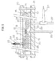
- FIG. 5 A device according to the first example is shown in Fig. 5 .
- This device has a culturing device for formation of a neuron network, constructed as a culturing planar patch-clamp device to serve as an ion channel biosensor.
- the electrical insulating plate 14 used in this device was a silicon plate.
- the plate 14 is provided with fine through-holes 15 having diameters of 1 to 3 ⁇ m, that allow communication between a first surface side (the top end in the diagram) and a second surface side (the bottom end in the diagram).
- one fine through-hole 15 is provided at the center of the plate 14, but a larger plate may be used and a plurality or many fine through-holes 15 provided, with the following construction applying to each of the fine through-holes 15.
- a cell plating section 13 is formed surrounded by a plurality of protrusions 12 on the plate surface above the opening on the first surface side of the fine through-hole 15, with one to several neurons 11 being placed in the cell plating section 13 (only one neuron is shown in the diagram for convenience).
- the plate 14 is sandwiched between the first surface side and second surface side by a pair of spacers 16, 17.
- the constituent material of the spacers 16, 17 is not restricted, but the spacer 16 on the first surface side is preferably an elastic, optically opaque material, and for example, silicon rubber, PDMS (polydimethylsiloxane) or the like may be used.
- the spacer 17 on the second surface side is preferably an optically transparent material.
- a notch as a large culturing space 18 for construction of a neuron network
- a notch on the plate 14 surface in this culturing space 18 there are formed one, several or many cell plating sections 13 in which a neuron 11 is placed (the diagram shows only a single cell plating section for convenience).
- Neurons 11 are also seeded at sections other than the cell plating section 13 on the plate 14 surface.
- a notched section 19 which is circular, for example, is formed at the section corresponding to the fine through-hole 15 of the plate 14, whereby the opening in the second surface side of the fine through-hole 15 opens out into the notched section 19.
- the notched section 19 may also be one, several or many, corresponding to the cell plating sections 13 and the fine through-holes 15 (although only one notched section 19 is shown in the diagram for convenience).
- the entirety of the plate 14 and the pair of spacers 16, 17 have a structure that is clamped by a pair of strong plates 20, 21.
- the material of the plates 20, 21 is not particularly restricted so long as it is a material that can withstand autoclave sterilization at about 120°C.
- the plate 20 on the first surface side is preferably made of an optically opaque material.
- the plate 21 on the second surface side is preferably made of an optically transparent material.
- a notched section that is circular, for example, is provided at the center section of the plate 20 on the first surface side, at a location corresponding to the culturing space 18 of the spacer 16 on the first surface side, having a size similar to that of the culturing space 18.
- a covering member such as cover glass may be placed on the step as a construction to allow opening and closing of the opening of the notched section in the spacer 16.
- a main pool 22 is thus constructed on the first surface side.
- a liquid pool section 23 is formed on the second surface side by using the plate 21 to plug the opening of the notched section 19 at the spacer 17 on the second surface side.
- the main pool 22 on the first surface side and the liquid pool section 23 on the second surface side are connected via the fine through-hole 15.
- the main pool 22 forms the first region of the liquid pool section on the first surface side.
- the main pool 22 is connected with a secondary pool 25 forming the second region of the liquid pool section on the first surface side, through a narrow liquid flow channel 24 provided in the spacer 16.
- the secondary pool 25 is formed by a hole formed through both the spacer 16 and the plate 20.
- An electrode section 28 on the first surface side, described below, is situated in the secondary pool 25.
- a cell culture medium as conducting liquid is introduced into and held in the liquid pool section on the first surface side composed of the main pool 22, liquid flow channel 24 and secondary pool 25. Neurons may be dispersed in the conducting liquid.
- the conducting liquid used may be a buffering solution comprising 140 mM NaCl, 3 mM KCl, 10 mM 4-(2-hydroxyethyl)-1-piperazineethanesulfonic acid (HEPES), 2.5 mM CaCl 2 , 1.25 mM MgCl 2 and 10 mM glucose at pH 7.4 (with HCl), or cell culture medium such as Dulbecco's modified Eagle's medium (DMEM: Sigma) with addition of 10% (v/v) FBS and 1% (v/v) GlutamaxTM (Gibco).
- the composition of the conducting liquid can be appropriately changed depending on the type of neuron.
- a buffering solution or cell culture medium known as a pipette solution, which may be 40 mM CsCl, 80 mM CsCH 3 SO 4 , 1 mM MgCl 2 , 10 mM HEPES, 2.5 mM MgATP, 0.2 mM Na 2 EGTA (pH 7.4).
- a pipette solution which may be 40 mM CsCl, 80 mM CsCH 3 SO 4 , 1 mM MgCl 2 , 10 mM HEPES, 2.5 mM MgATP, 0.2 mM Na 2 EGTA (pH 7.4).
- Introduction of the conducting liquid into the liquid pool section 23 is accomplished through a tubular liquid introduction flow channel 26, and discharge is accomplished by a liquid discharge flow channel 27.
- PEEK tubes with an outer diameter of 1 mm and an inner diameter of 0.5 mm were used for the liquid introduction flow channel 26 and liquid discharge flow channel 27, but the constituent materials of these liquid flow channels may be other materials instead, so long as the materials can withstand autoclave sterilization at about 120°C.
- an electrode section 29 on the second surface side formed in the same manner as the electrode section 28 on the first surface side (shown in outline fashion by a dash-dot line).
- the construction of the electrode sections 28, 29 will be described below. Normally, the electrode of the electrode section 28 on the first surface side is grounded, and a membrane voltage is applied to the electrode of the electrode section 29 on the second surface side.
- the suction pressure can form fine pores in the cell membrane of the neuron 11 at the portion contacting with the fine through-hole 15.
- a cell membrane pore-forming penetrating antibiotic such as nystatin or amphotericin B
- an extracellular matrix-forming substance 30 with cell-anchoring force may be adhered to the periphery of the opening on the first surface side of the fine through-hole 15 of the plate 14.
- the ion channel when the prescribed ion channel is being expressed on the neuron 11 and a stimulator that opens the ion channel is added to the liquid pool section on the first surface side, the ion channel opens and a channel current corresponding to the applied voltage flows between the electrode section 28 on the first surface side and the electrode section 29 on the second surface side.
- the seal resistance is lowered and leak current is superimposed on the channel current.
- the membrane potential has induced voltage by electromagnetic waves present between the space, an interface potential between the electrode metal surface and the buffering solution surrounding it, and a liquid/liquid interface potential, superimposed in addition to the voltage actually applied between the electrodes, and therefore the leak current varies in accordance with the variation in induced noise and interface potential.
- noise appears as fluctuation of the baseline with respect to the ion channel current.
- the structures of electrode sections 28, 29 on the first surface side and second surface side will now be described, without a detailed diagram.
- the interior of the tubular electrode receptacle 31 composed of Pyrex R glass with an inner diameter of 1 mm is filled with an electrode solution 32 with KCl and AgCl dissolved to saturated concentrations.
- the KCl concentration was 3.3 M/L and AgCl was added to approximately 1.1 mM/L.
- the saturated concentration is approximately 3.3 M/L at ordinary temperature.
- AgCl/Ag electrode 33 housed in the electrode receptacle 31 AgCl is coated onto the surface of a silver wire.
- Such an AgCl/Ag electrode 33 can be formed by coating AgCl powder onto the surface of a silver wire, or by dipping a silver wire into a bleaching agent or the like containing sodium hypochlorite. Alternatively, it can be formed by electroplating in a KCl solution.
- the tip section of the electrode receptacle 31 is plugged with an inorganic porous material 34 such as porous glass or porous ceramic.
- the inorganic porous material 34 actually used was Vycor glass (Corning, Inc.).
- the tip of the inorganic porous material 34 composing a part of the receptacle wall of the electrode receptacle 31 is dipped in a conducting liquid (cell culture solution or buffering solution).
- the KCl concentration in the conducting liquid is a few millimoles, but since mixing between the electrode solution 32 and the conducting liquid outside the receptacle is small enough to be ignored while the inside and outside of the electrode receptacle 31 are in a state of electrical conduction, due to the effect of the inorganic porous material 34, a large KCl concentration difference is maintained between the inside and outside of the receptacle, thereby maintaining a fixed AgCl/Ag electrode 33 interface potential and liquid/liquid interface potential.
- the base section of the electrode receptacle 31 is sealed with a sealant, and the electrode pin 35 protrudes from it.
- the electrode sections 28, 29 on the first surface side and the second surface side causes a liquid pool section on the first surface side to be formed by an optically opaque spacer 16 or plate 20, and therefore light irradiated onto the main pool 22 is not irradiated onto the AgCl/Ag electrodes of the electrode sections 28, 29 on the first surface side and the second surface side.
- a neuron 11 is placed in the main pool 22 and the potassium ion concentration of the conducting liquid on the exterior of the cell is as small as about several mM, it is preferred to minimize the effect of KCl leaking from the electrode section even if it is a trace amount, and for this purpose a secondary pool 25 is formed in addition to the main pool 22 in the liquid pool section on the first surface side, the main pool 22 and secondary pool 25 being connected by a narrow liquid flow channel 24 with a width of no greater than 1 mm.
- a second example is shown in Fig. 6 .
- the second example and the following third example further demonstrate in detail the essential points of the first example.
- the part numbers in these examples differ from those of the first example, but the same part names have essentially the same structures.
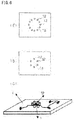
- a negative photoresist SU8 is coated onto the surface of a Si plate 1 to a thickness of 8 to 10 ⁇ m using a spinner, and a previously prepared photomask is used for development by a common process, to form a cell plating section 13 composed of a plurality of palisaded protrusions 12, examples of which are shown in Fig. 6(a) and Fig. 6(b) .
- the protrusions in this case are square columns with bottoms of 10 ⁇ m x 10 ⁇ m and heights of 8 to 10 ⁇ m, the mutual gaps between the protrusions being 8 to 10 ⁇ m.
- the diameters of mouse or rat cerebral cortical or hippocampal neuronal cell bodies are generally about 10 ⁇ m when seeded and 15 to 20 ⁇ m when plated, and therefore the neuron 3 situated in the cell plating section 2 formed by the plurality of protrusions does not migrate out of the cell plating section 2.
- the cell culture medium migrates into the cell plating section 2 so that culturing of the cell takes place satisfactorily in the cell plating section 2.
- the shapes of the protrusions may be circular columnar or elliptic cylindrical, and may even be solid spherical.
- Placement of the neurons 3 by the cell plating section 13 composed of the plurality of protrusions 12 is useful for formation of a neuron network.
- placing a neuron 3 on the inside of the cell plating section 13 results in formation of a network with the neurons 3 on the outside of the cell plating section 13.
- the neuron 3 undergoes elongation of the axon to bind with adjacent neurons, while neurotransmitters are released from the tip of the axon, while the neurons 3 at the receiving end receive the neurotransmitters and extend their dendrites, forming synaptic junctions.
- the neuron 3 inside the cell plating section 13 and the neurons 3 outside the cell plating section 13 are present on the same flat surface of the plate 1, so that communication between the neurons is accomplished without interference, stable culturing is continued, and a stable network is formed.
- the neuron 3 situated inside the cell plating section 2 could be cultured for a month or longer.
- the inner diameter of the cell plating section 13 can be easily changed as shown in Fig. 6(a) and Fig. 6(b) .
- the inner diameter may be the inner diameter allowing numerous (comparatively numerous) neurons 3 to be placed for stable culturing of the neuron network for a prolonged period, or an inner diameter allowing one to a small number of neurons 3 to be placed for easy functional analysis of a network, determined based on the optimal number of neurons (cluster size) for the purpose.
- cluster size for example, a cluster of 1 to 4 is satisfactory for relatively hardy rat cerebral cortical neurons, but with relatively fragile iPS cells or neurospheres differentiated and induced from them, clusters comprising more numerous cell bodies are preferred for stable culturing.
- FIG. 7 the circled section labeled "c" at the bottom right of Fig. 7 (A) is a magnified section of the cross-section near the fine through-hole 4 at the center section of the cell plating section 2.
- the culturing planar patch-clamp has a construction with a fine through-hole 4 with a diameter of 1 to several ⁇ m formed in a plate 1 such as Si, or plastic, ceramic or glass, a neuron 3 being placed over the fine through-hole 4, and a prescribed buffering solution filling both above and below the plate 1, and with an upper electrode 7 and lower electrode 8 installed.
- the lower electrode 8 is connected to a current amplifier 5.
- Fine pores are opened in the cell membrane of the neuron 3 contacting with the fine through-hole 4, forming a whole-cell state with electrical conduction between the neuron 3 and the buffering solution pool below the plate 1.
- the method of opening fine pores in the neuron 3 is a method of applying negative pressure to the lower liquid pool to breach the cell membrane, as explained for the first example.
- Another method involves causing a buffering solution dissolving antibiotics such as nystatin and amphotericin to flow into the lower liquid pool, and implanting the antibiotics into the cell membrane to produce a state of electrical conduction between the cell interior and the lower liquid pool.
- an extracellular matrix-forming substance 9 onto the surface of the plate 1 surrounding the fine through-hole 4 is effective for prolonging the lives of the neurons 3. While many extracellular matrix-forming substances 9 are known, poly-L-lysine and laminin are among those more well known. For seeding of the neurons 3 into the system, it is particularly effective to utilize a micropipette 6 such as shown in the diagram, since it is necessary to reliably seed a single cell or a plurality of cells inside the cell plating section 2.
- the suspension of a neuron 3 is injected onto the cell plating section 2 at a prescribed rate from the micropipette 6 while a prescribed negative pressure is applied to the lower liquid pool, so that the neuron 3 can be efficiently placed on the fine through-hole 4 as shown in Fig. 7 (B) . If the negative pressure is too great, however, the neurons 3 will die, and therefore appropriate pressure must be set for each type of cell. In Fig. 7 (B) , in a suction experiment using HEK293 cells, it was confirmed that neurons 3 do not suffer damage if the negative pressure is 2 kPa.
- a probe molecule for Ca imaging was introduced into the neurons 3 beforehand.
- the neurons 3 also expressed photoreceptor ion channels such as channel rhodopsin by gene transfer, allowing stimulation by light such as laser light.
- the excitation wavelength of the channel rhodopsin utilized in this example was 470 to 480 nm, while the Ca probe used was Oregon Green BAPTA-1 having an excitation wavelength of 494 nm and a luminous wavelength of 523 nm.
- the operational modes implemented in this third example were the following four types.
- a prescribed membrane potential (normally from -80 to +80 mV) is applied to the neuron 3 on the fine through-hole 4 by an upper electrode 7 and a lower electrode 8, and the ion channel current flowing in the neuron 3 by spontaneous firing is observed in whole-cell mode (arrow symbol "a" in Fig. 7(A) ).
- synaptic current of Na + , K + , Cl - and the like is observed with the inflow of Ca ion by spontaneous firing of the surrounding neurons 3 and the reception of neurotransmitters ( K.S. Wilcox et al., Synapse 18 (1994) 128-151 ), and this can yield information regarding the state of the axons and the state of the neurons 3.
- a prescribed current is injected into the neuron 3 on the fine through-hole 4 by the upper electrode 7 and the lower electrode 8, or voltage is applied (the arrow symbol “b” in Fig. 7 (A) ) to stimulate the neuron 3 and generate an action potential.
- This causes influx of Ca ions into the stimulated neuron 3.
- the fluorescence of the Ca probe is observed (the arrow symbol “d1” in Fig. 7 (A) ), while the generated action potential is propagated to the surrounding neurons 3, producing luminescence of the Ca probe in the surrounding neurons 3 (the arrow symbol "d2" in Fig. 7 (A) ). Observation of this luminescence allows propagation of the signal to be confirmed. That is, information can be obtained regarding the signal propagation properties of the neuron network.
- Laser light of 470 to 480 nm is focused and irradiated on a single neuron 3 present near the neuron 3 on the fine through-hole 4 (in the cell plating section 2) and expressing channel rhodopsin (the arrow symbol "e” in Fig. 7 (A) ), generating an action potential in the single neuron 3.
- the action potential signal is propagated to the neuron 3 on the fine through-hole through the network, and the Ca channels are opened inducing influx of Ca ions.
- the signal propagation properties of the neuron network can be measured on the single cell level and analyzed in detail.
- the structure shown in Fig. 7(A) which is a combination of the cell plating section 2 and the fine through-hole 4, operates as an element so long as at least one location is present. Also, if a plurality of such structures are formed on the plate 1, it will operate as a high throughput screening device.
- an element is constructed having structures as shown in Fig. 7(A) , i.e. one each corresponding to the trigger cell and the follower cell.
- a system that is a combination of a fine through-hole 4 and cell plating section 2 as shown in Fig. 7(A) is formed at multiple locations on the plate 1.
- An action potential is generated in several of the neurons 3 on the fine through-hole 4 (trigger cells) by current injection or voltage application. Also, propagation of the action potential to the other neurons 3 on the fine through-hole 4 (follower cells) can potentially be analyzed by recording the ion channel current of the follower cells in whole-cell mode. In these devices it is very important for the neurons 3 to be placed at specified locations, and it is obvious that the invention is highly useful for formation of a stable neuron network with specified locations.
- Fig. 8(a) and (b) The fourth example is illustrated in Fig. 8(a) and (b) .
- Fig. 8(a) which is a flat photograph
- a cell plating section 2 comprising circular columns 12 with diameters of about 10 ⁇ m and heights of about 8 ⁇ m, appearing as a small circle, has been formed on the surface of a Si plate
- neurons 3 harvested from 17-day-old rat embryonic cerebral cortex have been seeded, and formation of a neuron network after 14 days of culturing has been confirmed with a fluorescent microscope.
- Fig. 8(b) shows the results of observing the time-dependent change in fluorescence intensity of the neurons 3 inside the cell plating section 2, where there can be seen repeated active spontaneous firing of the neurons 3 and fluctuation in the Ca concentration inside the neurons 3.
- only one the cell plating section 2 group is set, but if numerous such groups are set it is possible to observe the state of signal propagation from a specific cell plating section 2 to another cell plating section 2, and to accurately and stably carry out functional analysis of a network.
- a fifth example is shown in Fig. 9 .
- Neurons harvested from rat embryonic cerebral cortex were seeded by the same method as the fourth example, and after 14 days of culturing, it was confirmed that the neurons in the cell plating section were situated on the fine through-hole and that the neurons had formed a network with the surrounding neurons.
- the media on the top side of the plate and the bottom side were each exchanged with prescribed buffering solutions, a 500 ⁇ g/ml concentration of nystatin was mixed with the buffering solution on the bottom side, and after standing for approximately 10 minutes, the current flowing into an electrode set on the bottom side of the plate 1 in a whole-cell mode configuration was detected with a current amplifier (Axopatch200B).
- Fig. 9(A) shows the membrane potential dependency of the current.
- 40 mV-TTX is the current observed with a membrane potential of 40 mV, when the Na channel blocker tetrodotoxin (TTX) had been mixed with the buffering solution on the top side.
- TTX Na channel blocker tetrodotoxin
- Fig. 9(B) and Fig. 9(C) show in summary the results of measuring the time-dependent change in fluorescence intensity by Ca imaging of each of the neurons, from above the plate.
- the abscissa represents time, and the ordinate represents the numbers assigned to each of the neurons.
- the sizes of the circles represent the strengths of Ca fluorescence intensity.
- the density of the neurons was low at only 2 x 10 5 per 35 mm dish, and the luminescence from the neurons was completely random.
- the sixth example corresponds to a modified example of the cell plating section 13.
- a cell plating section 13 is formed surrounded by a plurality of protrusions 12 in the same manner as the first example, on the plate surface above the opening on the first surface side of the fine through-hole, with the neurons 11 placed in the cell plating section 13.
- An outer cell plating section 36 is also formed on the outside of the plurality of protrusions 12 forming the cell plating section 13 in a ring shape, and further surrounded by numerous protrusions 12. That is, according to the sixth example, the rings that are formed by the protrusions 12 are in a double ring structure with the cell plating section 13 and the outside cell plating section 36.
- Fine through-holes are present in the cell plating section 13 which is the region surrounded by the inner ring, and in this region there are plated 1 to several neurons 11, the neurons 11 being definitely situated on the fine through-hole.
- Numerous neurons 11 are simultaneously seeded in the outer cell plating section 36, which is the region between the inner ring and the outer ring.
- a neuron network is formed not only between the neurons 11 inside the cell plating sections 13 but also between the neurons 11 of the cell plating sections 13 and the neurons 11 of the outer cell plating sections 36.
- Such a structure comprising cell plating sections 13 and outer cell plating sections 36 is advantageous in that neurons that are unstable as single cells and cannot be stably cultured without aggregation of a large number of cells, such as iPS cells for example, can be reliably plated as single neurons each on a fine through-hole, while being cultured for prolonged periods in a stable manner.
- a seventh example will now be briefly described as an example of a method of seeding neurons 11 separately in a cell plating section 13 and an outer cell plating section 36 according to the sixth example.
- the seventh example corresponds to a neuron seeding device according to the invention.
- the device body of the neuron seeding device is a device for seeding of neurons in multiple cell plating sections surrounded by a plurality of protrusions on an apparatus plate, set on the apparatus plate of the culturing device for formation of a neuron network or the planar patch-clamp device according to the example described above.
- the device body 40 of the neuron seeding device is a flat board having a thickness of about 4 to 6 mm and a square planar shape of about 2 x 2 cm, and it comprises an upper board 41 and a lower board 42.
- the upper board 41 and lower board 42 are each composed of a transparent plastic such as PDMS (polydimethylsiloxane), PMMA (polymethyl methacrylate) or the like or silicon rubber, that has been surface-cleaned by plasma treatment, for example, and they are heat-bonded together in a closely joined state to form a two-layer structure.
- PDMS polydimethylsiloxane
- PMMA polymethyl methacrylate
- a suspension supply port 43 forming a first suspension flow channel system, for external supply of a neuron suspension comprising neurons suspended at a fixed density. Also, at the other side of the center section on the top side there is opened a second suspension supply port 43a forming a second suspension flow channel system.
- the first suspension flow channel system will be explained first.
- the second suspension flow channel system will be explained below.
- the first suspension flow channel system comprises a suspension supply port, a suspension flow channel and a suspension injection port according to the ninth invention to twelfth invention.
- a cross-sectional view (partially simplified) along line X-X in Fig. 11(a) is shown in Fig. 11(b) , and as shown in Fig. 11(b) , fine grooves with inner diameters and depths of both about 50 to 500 ⁇ m extend in a branched fashion from the suspension supply port 43 on the bottom side of the upper board 41 (the bonding surface with the lower board 42).
- fine grooves with inner diameters and depths of both about 50 to 500 ⁇ m extend in a branched fashion from the suspension supply port 43 on the bottom side of the upper board 41 (the bonding surface with the lower board 42).
- Fig. 12(a) shows a lower view (bottom side view) of the upper board 41. While Fig. 11(b) shows only a single suspension flow channel 44, in actuality a plurality of suspension flow channels 44 extend in a branched fashion from the suspension supply port 43 shown at the lower end of the drawing, as seen in Fig. 12(a) . By providing extra by-pass routes at appropriate locations in these suspension flow channels 44, the flow channel lengths can be adjusted to be nearly equivalent.
- suspension flow channels 44 are represented simply by dark solid lines for convenience.
- the second suspension flow channel 44a shown here and described below, is also represented simply by a dark solid line.
- Fig. 12(b) conceptually shows a top view (plan view) of the plate 1 of a culturing device for formation of a neuron network or a planar patch-clamp device, illustrating five designated plating areas each with a plurality of cell plating sections 2 surrounded by a plurality of protrusions on the top side of the plate 1 (indicated by single dots for simplicity) set in a collective manner.
- Fig. 12(b) also shows second suspension injection ports 45a, which are described below, although these are in actuality formed by the lower board 42 and not formed on the plate 1, but merely shown in order to highlight the positional relationship with the aforementioned five designated plating areas.
- the plurality of suspension flow channels 44 extending in a branched fashion from the suspension supply port 43 each arrive at a point right above the five designated plating areas in which the plurality of cell plating sections 2 on the plate 1 are set in a collective manner, and at those locations they form five injection hole sections 46 communicating with the plurality of suspension injection ports 45 formed on the lower board 42.
- Fig. 13 shows a magnified view of the injection hole sections 46.
- the suspension flow channel 44 branches into 5 longitudinal flow channels, and the five branched flow channels are each connected to one of a plurality of suspension injection ports 45 provided in the lower board 42. That is, as shown in Fig. 12(b) , five rows of cell plating sections 2 are formed in the longitudinal direction in the five designated plating areas on the plate 1, with five cell plating sections 2 included in each row, and five rows of flow channels are situated running in the longitudinal orientation of the suspension flow channels 44, completely corresponding to all of the cell plating sections 2, while suspension injection ports 45 are also formed in the lower board 42, completely corresponding to all of the cell plating sections 2.
- the inner diameters of the suspension injection ports 45 are essentially the same as or slightly larger than the sizes of the interior regions of the cell plating sections 2, but smaller than the outer shapes of the cell plating sections 2 including the protrusions 12. Thus, the construction is such that the protrusions 12 do not enter into the suspension injection ports 45.
- the neuron suspension when the neuron suspension is supplied in a pressurized state, for example, to the suspension supply ports 43 composing the first suspension flow channel system, the neuron suspension is injected into all of the total of 250 cell plating sections 2 provided in the five designated plating areas on the plate 1 through the suspension flow channels 44 and the suspension injection ports 45, in a very short period of time and in essentially equal amounts to all.
- neurons are seeded in the cell plating sections 2, according to the preferred mode described above under "Effect of the Invention".
- the second suspension flow channel system is a suspension flow channel system for injection of a neuron suspension into the regions other than the cell plating sections of the apparatus plate, according to the thirteenth invention, comprising the second suspension supply port 43a shown in Fig. 11(a) , a plurality of second suspension flow channels 44a extending in a branched fashion from the second suspension supply port 43a as shown in Fig. 12(a) , and second suspension injection ports 45a formed on the lower board 42 at each of the ends of the second suspension flow channels 44a.
- Each of the second suspension injection ports 45a are shown as broken lines in Fig. 12(a) , and as solid lines in Fig. 12(b) .
- the structural relationship between the second suspension supply ports 43a, second suspension flow channels 44a and second suspension injection ports 45a is the same as for the suspension supply port 43, suspension flow channel 44 and suspension injection port 45 shown in Fig. 11(b) , for the first suspension flow channel system.
- the flow channel lengths of the plurality of second suspension flow channels 44a may be different, or the second suspension injection ports 45a may open into regions other than the cell plating sections on the plate 1, as shown in Fig. 12(b) .
- neurons are seeded into regions other than the cell plating sections on the plate 1, through the second suspension flow channels 44a and the second suspension injection ports 45a.
- third suspension flow channels (not shown) for seeding of neurons into the outer cell plating sections 36 may also be formed in the device body 40 in addition to the suspension flow channels 44 and second suspension flow channels 44a, into seed neurons in the outer cell plating sections 36 in the device body 40.
- neurons may be seeded in the outer cell plating sections 36 utilizing the suspension flow channels 44 after the location of the device body 40 on the plate 1 has been slightly shifted.
- the first suspension flow channel system formed in the device body 40 of the neuron seeding device is utilized to inject a prescribed concentration of neuron suspension into each of the cell plating sections 2. Also, since the mutual gaps between the plurality of protrusions 12 of the cell plating sections 2 are smaller than the dimensions of the neuronal cell bodies during seeding, with sufficient room allowing easy flow of the medium solution of the neuron suspension (for example, the neuron culture solution), introduction of the neuron suspension from above the cell plating sections 2, with flow of the medium solution, causes the neurons to pool inside the cell plating sections 2 and be seeded therein.
- the medium solution of the neuron suspension for example, the neuron culture solution
- neuronal cell bodies generally differ in their sizes during seeding and during culturing. Also, the cell body shapes are not perfectly round but rather elongated ellipsoid.
- the mutual gaps between protrusions 12 it is necessary for the mutual gaps between protrusions 12 to be smaller than the smaller value of the minimum dimension of the cell body during seeding (the dimension in the short axis direction) and the minimum dimension of the cell body during culturing, but it is also necessary for them to be formed as large as possible so as to allow the medium solution of the neuron suspension to easily flow out and so that the neuronal axons or dendrites can easily move into and out of the cell plating sections 2.
- Fig. 14 the distribution of the maximum dimension (the dimension in the long axis direction) during seeding of numerous rat hippocampal neurons is shown in the graph at the left, and the distribution of the minimum dimension (the dimension in the short axis direction) is shown in the graph at the right).
- the minimum dimension of the cell bodies during seeding was approximately 7.5 ⁇ m.
- Fig. 15 the distribution of the maximum dimension (the dimension in the long axis direction) during culturing of the same cell bodies is shown in the graph at the left, and the distribution of the minimum dimension (the dimension in the short axis direction) is shown in the graph at the right).
- the cell bodies were long and narrow during culturing, with the minimum dimensions of the cell bodies being approximately 8 ⁇ m.
- Fig. 16 is an optical microscope photograph of the state of neurons on the 4th day of culturing, the four large circles in the photograph being four groups of protrusions 12 forming cell plating sections 2, and the outlines indicated by white solid lines representing neurons.
- a neuron is attempting to infiltrate the cell plating section 2 through a gap between the protrusions 12, from the outside. This neuron in fact did not infiltrate but regressed after some elapse of time.
- the gaps between the protrusions 12 were 11 ⁇ m, and the dimensions of the neuronal cell bodies in the short axis direction were 8.5 ⁇ m. In the case shown in Fig. 16 , therefore, this shows that it is safer for the gaps between the protrusions 12 to be somewhat smaller.
- the ninth example corresponds to a method of preparing a rat neuron suspension to be used for seeding.
- the suspension was prepared in the following manner. Specifically, cerebral cortexes or hippocampi were harvested from 17- to 18-day-old Wistar Rat fetal brains and the tissue was dispersed with enzyme treatment (37°C, 20 minutes) using a 0.25% Trypsin solution. Next, a cell suspension was prepared at 1.0 x 10 7 cells/ml using serum-containing medium with Minimum Essential Medium (MEM) as the basal medium. The cell suspension was introduced and seeded in the cell plating sections using a microflow device or microinjector.
- MEM Minimum Essential Medium
- the tenth example corresponds to preparation of iPS cells to be seeded.
- the human induced pluripotent stem cell (iPS cell) strain 201B7 was obtained from CELL BANK by the independent administrative institution RIKEN (Japan), and STO cell-derived cells (SNL), rendered proliferation impotent by inactivation with mitomycin C, were cultured as feeder cells.
- Feeder cells are other cells that play a role in aiding in auto-replication of iPS cells.
- the culture solution used was mammalian cell-culturing medium (DMEM/F12 medium) containing KSR as serum replacement, L-glutamine, non-essential amino acids and 2-mercaptoethanol, and it was added immediately before using recombinant human basic fibroblast growth factor (bFGF). Seeding was in a 6 cm dish coated appropriately for feeder cells, with a feeder cell concentration of 3 x 10 4 cells/cm 2 , and the iPS cells were seeded on the feeder cells after one day. Satisfactory iPS cells have distinct colony outlines and high inner cell densities. Subcultures of iPS cells are usually at a frequency of once every 3 to 4 days. After subculturing of 3 to 4 generations, in order to induce differentiation to motor neurons, the cells were transferred from culturing on the feeder to a 6 cm dish surface-coated with gelatin or Matrigel, for feederless culturing.
- DMEM/F12 medium mammalian cell-culturing medium
- KSR as serum replacement
- the feederless cultured iPS cells were induced to differentiate to neural stem cells by suspension culture in the presence of a growth factor.
- the differentiation-inducing medium was DMEM/F12 medium containing added glucose, glutamine, insulin, transferrin, progesterone, putrescine and selenium chloride.
- the suspension culture step for inducing differentiation was suspension culturing for 2 days at a density of 5 x 10 4 cells/ml. The medium was then exchanged with differentiation-inducing medium containing added retinoic acid (10 -8 M), and suspension culturing was carried out for 4 days.
- the neural stem cells were dispersed and adhesion culturing was carried out on a culturing dish coated with poly-L-lysine, and differentiation to mature motor neurons occurred by 5 weeks after the start of adhesion culturing.
- the neuron network was to be formed on a sensor plate
- the plate surface was coated with poly-L-lysine and the dispersed neural stem cells were seeded on it and adhesion cultured for 5 weeks, after which a network containing motor neurons formed.
- the plate surface was coated with poly-L-lysine and the dispersed neural stem cells were seeded on it and adhesion cultured for 5 weeks, upon which a network containing motor neurons formed.
- a culturing device for formation of a neuron network, allowing a satisfactory neuron network to be constructed with neurons in a live state in cell culture medium while restricting their movement, as well as a means of utilizing the same.
Landscapes
- Health & Medical Sciences (AREA)
- Engineering & Computer Science (AREA)
- Life Sciences & Earth Sciences (AREA)
- Chemical & Material Sciences (AREA)
- Bioinformatics & Cheminformatics (AREA)
- Organic Chemistry (AREA)
- Wood Science & Technology (AREA)
- Zoology (AREA)
- Biomedical Technology (AREA)
- Biotechnology (AREA)
- Genetics & Genomics (AREA)
- Biochemistry (AREA)
- General Health & Medical Sciences (AREA)
- General Engineering & Computer Science (AREA)
- Microbiology (AREA)
- Sustainable Development (AREA)
- Physics & Mathematics (AREA)
- Molecular Biology (AREA)
- Cell Biology (AREA)
- Neurology (AREA)
- Clinical Laboratory Science (AREA)
- Immunology (AREA)
- Electromagnetism (AREA)
- Neurosurgery (AREA)
- Medicinal Chemistry (AREA)
- Analytical Chemistry (AREA)
- Food Science & Technology (AREA)
- Urology & Nephrology (AREA)
- General Physics & Mathematics (AREA)
- Pathology (AREA)
- Hematology (AREA)
- Biophysics (AREA)
- Apparatus Associated With Microorganisms And Enzymes (AREA)
- Micro-Organisms Or Cultivation Processes Thereof (AREA)
- Investigating, Analyzing Materials By Fluorescence Or Luminescence (AREA)
- Virology (AREA)
Claims (11)
- Planare Patch-Clamp-Vorrichtung zum Analysieren eines Neuronennetzwerks, welche aufweist:eine elektrisch isolierende Platte (2) mit einer ein Neuronennetzwerk bildenden Seite und einer zweiten Oberflächenseite auf der gegenüber liegenden Seite, die mindestens eine Durchgangsöffnung aufweist, die eine Kommunikation zwischen den beiden Seiten ermöglicht und die einen solchen Durchmesser aufweist, dass die Neuronen nicht dadurch gehen (4) können,Flüssigkeitsreservoirabschnitte (5) and (6), die an jeder Seite der Oberflächen der elektrisch isolierenden Platte gebildet worden sind, die ermöglichen, das Zellkulturmedium zu halten, und die miteinander durch die feine(n) Durchgangsöffnung(en) verbunden sind,einen Elektrodenabschnitt, der auf der das Neuronennetzwerk bildenden Seite vorgesehen ist und der angeordnet ist, um elektrisch leitend mit dem Zellkulturmedium (8) zu sein,einen zweiten Elektrodenabschnitt, der auf der zweiten Oberflächenseite vorgesehen ist, um elektrisch leitend mit der leitenden Flüssigkeit (9) zu sein, wobei(a) ein Zellplattierungsabschnitt, der von einer Anzahl von Vorsprüngen umgeben ist, die auf der ersten Oberfläche auf eine solche Weise gebildet worden ist, dass die Vorsprünge die Bewegung der Zellen (11) begrenzen, aber die Bildung eines Neuronennetzwerks (12) ermöglichen,(b) die Durchgangsöffnung in dem Zellplattierungsabschnitt (13) angeordnet ist,(c) die Plattierungsoberfläche, die den Boden des Zellplattierungsabschnitts bildet, mit einer extrazellulären, eine Matrix bildenden Substanz (14) beschichtet worden ist, und(d) der Durchmesser des Zellplattierungsabschnitts, der durch die Anzahl der Vorsprünge bestimmt ist, eine Größe aufweist, die es ermöglicht, einen Zellkörper (15) oder mehrere Zellkörper (15) aufzunehmen.
- Planare Patch-Clamp-Vorrichtung zum Analysieren eines Neuronennetzwerks nach Anspruch 1, wobei die Umgebungen der Durchgangsöffnungen mit einer extrazellulären, eine Matrix bildenden Substanz (14) beschichtet sind.
- Planare Patch-Clamp-Vorrichtung zum Analysieren eines Neuronennetzwerks nach Anspruch 1 oder 2, wobei die Anzahl der Zellplattierungsabschnitte, die durch die Anzahl der Vorsprünge bestimmt ist, auf der Platte (16) angeordnet sind.
- Planare Patch-Clamp-Vorrichtung zum Analysieren eines Neuronennetzwerks nach einem der Ansprüche 1 bis 3, wobei ein Zellkörper oder mehrere Zellkörper in dem Zellplattierungsabschnitt angeordnet ist / sind und ein anderer Zellkörper außerhalb des Zellplattierungsabschnitts (17) angeordnet ist.
- Planare Patch-Clamp-Vorrichtung zum Analysieren eines Neuronennetzwerks nach einem der Ansprüche 1 bis 4, dadurch gekennzeichnet, dass die Elektrodenabschnitte auf der ersten Oberflächenseite und der zweiten Oberflächenseite aufweisen:einen Elektrodenanschluss, wobei mindestens ein Bereich der Anschlusswand, die in Kontakt mit der leitenden Flüssigkeit ist, wenn die leitende Flüssigkeit in die Flüssigkeitsreservoirabschnitte eingeführt wird, aus einem anorganischen Material worden gebildet ist,eine Elektrode, welche eine Schicht aus einem Edelmetallchlorid (NmCl) aufweist, die auf einem Oberflächenschichtabschnitt des Edelmetalls (Nm) gebildet worden ist, und welche in dem Elektrodenanschluss aufgenommen worden ist, undeine Elektrodenlösung, die in den Elektrodenanschluss gefüllt worden ist, wobei das Edelmetallchlorid (NmCl) und ein Alkalimetallchlorid auf eine gesättigte Konzentration (18) gelöst worden sind.
- Planare Patch-Clamp-Vorrichtung zum Analysieren eines Neuronennetzwerks nach einem der Ansprüche 1 bis 5, dadurch gekennzeichnet, dass die Vorrichtung zur Messung und Analyse eines Kanalstroms eines neuralen Ions oder zur Abbildungsanalyse (19) verwendet wird.
- Planare Patch-Clamp-Vorrichtung zum Analysieren eines Neuronennetzwerks nach einem der Ansprüche 1 bis 6, welche ferner aufweist:einen Fotodetektor, um das Licht zu erfassen, das von den Neuronen (20) emittiert wird, undeine Bestrahlungsvorrichtung, die Licht auf die Neuronen oder die Plattenoberfläche bestrahlt.
- Neuronenbildungsvorrichtung, um Neuronen in mehreren Zellplattierungsabschnitten zu bilden, die von der Anzahl der Vorsprünge auf einer Platte einer planaren Patch-Clamp-Vorrichtung nach Anspruch 1 umgeben sind, wobei die Neuronenbildungsvorrichtung aufweist:(1) einen Suspensionszufuhranschluss, um extern eine Zellsuspension zuzuführen,(2) eine Anzahl an feinen Suspensionsflusskanälen, die sich auf eine verzweigte Weise von dem Suspensionszufuhranschluss in dem Inneren des Vorrichtungskörpers erstrecken, und(3) einen Suspensionsinjektionsanschluss, um die Zellsuspension in jeden Zellplattierungsabschnitt zu injizieren, der an dem Boden des Vorrichtungskörpers an dem Ende von jedem der Suspensionsflusskanäle offen ist,wobei die Neuronenbildungsvorrichtung ein plattenförmiger Vorrichtungskörper ist, der auf die Apparatplatte gesetzt werden kann und der eine Größe aufweist, welche die mehreren Zellplattierungsabschnitte bedeckt, und wobei der flache Boden des Vorrichtungskörpers in Kontakt mit den Spitzen der Anzahl der Vorsprünge der mehreren Zellplattierungsabschnitte in der gesetzten Stellung (22) ist.
- Neuronenbildungsvorrichtung nach Anspruch 8, dadurch gekennzeichnet, dass die Anzahl der Suspensionsflusskanäle auf eine solche Weise gesetzt worden ist, dass sie im Wesentlichen die gleiche Länge aufweisen, und dass die Ausgestaltung auf eine solche Weise ist, dass wenn die Neuronenbildungsvorrichtung auf die Apparatplatte der Kultivierungsvorrichtung zum Bilden des Neuronennetzwerks oder der planaren Patch-Clamp-Vorrichtung angebracht wird, die einzelnen Suspensionsinjektionsanschlüsse auf eine solche Weise angeordnet sind, dass sie genau den einzelnen Zellplattierungsabschnitten (23) entsprechen.
- Neuronenbildungsvorrichtung nach Anspruch 8 oder 9, dadurch gekennzeichnet, dass der plattenförmige Vorrichtungskörper eine obere Steckkarte, die mit den Suspensionszufuhranschlüssen versehen ist, und eine untere Steckkarte aufweist, die mit den Suspensionsinjektionsanschlüssen versehen ist, die in einem dicht verbundenen Zustand verbunden sind, und dass die Rillen, welche die Suspensionsflusskanäle bilden, auf mindestens einem von den Bindungsoberflächen der oberen Steckkarte und der unteren Steckkarte (24) gebildet worden sind.
- Neuronenbildungsvorrichtung nach einem der Ansprüche 8 bis 10, wobei der Vorrichtungskörper ferner ein zweites System an Suspensionsflusskanälen aufweist, um die Neuronensuspension in andere Bereiche als die Zellplattierungsabschnitte der Apparatplatte der Kultivierungsvorrichtung zur Bildung eines Neuronennetzwerks oder der planaren Patch-Clamp-Vorrichtung (25) zu injizieren.
Applications Claiming Priority (2)
| Application Number | Priority Date | Filing Date | Title |
|---|---|---|---|
| JP2012205561 | 2012-09-19 | ||
| PCT/JP2013/057976 WO2014045618A1 (ja) | 2012-09-19 | 2013-03-21 | 神経細胞ネットワークの形成及びその利用、並びに神経細胞播種デバイス |
Publications (3)
| Publication Number | Publication Date |
|---|---|
| EP2899262A1 EP2899262A1 (de) | 2015-07-29 |
| EP2899262A4 EP2899262A4 (de) | 2016-04-27 |
| EP2899262B1 true EP2899262B1 (de) | 2017-08-09 |
Family
ID=50340951
Family Applications (1)
| Application Number | Title | Priority Date | Filing Date |
|---|---|---|---|
| EP13838905.1A Active EP2899262B1 (de) | 2012-09-19 | 2013-03-21 | Herstellung und verwendung eines neuronalen netzes sowie neuroneneinpflanzvorrichtung |
Country Status (9)
| Country | Link |
|---|---|
| US (1) | US9829477B2 (de) |
| EP (1) | EP2899262B1 (de) |
| JP (1) | JP6047579B2 (de) |
| KR (1) | KR102027808B1 (de) |
| CN (1) | CN104640971B (de) |
| DK (1) | DK2899262T3 (de) |
| SG (1) | SG11201502017SA (de) |
| TW (1) | TWI598830B (de) |
| WO (1) | WO2014045618A1 (de) |
Families Citing this family (14)
| Publication number | Priority date | Publication date | Assignee | Title |
|---|---|---|---|---|
| EP3040410B1 (de) | 2013-08-30 | 2018-04-25 | Japan Science and Technology Agency | Flache patch-clamp-vorrichtung und verfahren verwendend die patch-clamp vorrichtung |
| US10208284B2 (en) | 2014-01-24 | 2019-02-19 | Japan Science And Technology Agency | Cell-seeding and -culturing device |
| WO2016088243A1 (ja) * | 2014-12-05 | 2016-06-09 | 株式会社ニコン | 判定装置、観察システム、観察方法、そのプログラム、細胞の製造方法、および細胞 |
| US20160311699A1 (en) | 2015-04-21 | 2016-10-27 | Chris Burseth | Device and system to improve asepsis in dental apparatus |
| KR101979145B1 (ko) * | 2018-01-30 | 2019-05-15 | 서강대학교산학협력단 | 신경줄기세포 배양용 미세유체칩 및 이의 용도 |
| CN112513631A (zh) * | 2018-08-03 | 2021-03-16 | 奥林巴斯株式会社 | 细胞检查装置和细胞检查方法 |
| JP2020110117A (ja) * | 2019-01-15 | 2020-07-27 | 株式会社島津製作所 | 細胞処理容器及び細胞処理装置 |
| JP7231168B2 (ja) * | 2019-11-14 | 2023-03-01 | Nok株式会社 | 細胞外電位測定装置 |
| KR102512332B1 (ko) | 2019-12-24 | 2023-03-22 | 광운대학교 산학협력단 | 신경세포의 신호전달 학습이 가능한 바이오닉 뉴럴 인공지능 프로세서 |
| US20210301240A1 (en) * | 2020-03-30 | 2021-09-30 | Ricoh Company, Ltd. | Cell-containing container and method for producing same |
| NL2025441B1 (en) * | 2020-04-28 | 2021-11-09 | Biond Solutions B V | All-in-one microchamber for 3D muscular tissues |
| KR102512331B1 (ko) | 2020-05-06 | 2023-03-22 | 광운대학교 산학협력단 | 신경세포의 신호 전달 체계를 이용하여 비정형적 연산의 출력이 가능한 바이오닉 뉴럴 인공지능 프로세서 |
| JP7721879B2 (ja) * | 2020-07-30 | 2025-08-13 | 株式会社リコー | 神経細胞ネットワーク構造体の形成方法、及びインビトロで神経細胞を評価する方法 |
| WO2024079699A1 (en) * | 2022-10-13 | 2024-04-18 | Neural Automations Ltd. | Micro-electrode arrays for electrical interfacing |
Family Cites Families (20)
| Publication number | Priority date | Publication date | Assignee | Title |
|---|---|---|---|---|
| JP3126269B2 (ja) | 1993-09-07 | 2001-01-22 | 株式会社バイオマテリアル研究所 | 培養基質 |
| DK1264877T3 (da) | 2000-03-16 | 2013-10-28 | Cellseed Inc | Celledyrkningsbæremateriale, fremgangsmåde til samdyrkning af celler og samdyrket cellelag opnået derved |
| US7270730B2 (en) * | 2000-08-04 | 2007-09-18 | Essen Instruments, Inc. | High-throughput electrophysiological measurement system |
| EP1372828A4 (de) * | 2001-03-24 | 2008-10-29 | Aviva Biosciences Corp | Biochips mit ionentransporterfassungsstrukturen und verwendungsverfahren |
| TW200415524A (en) * | 2002-10-24 | 2004-08-16 | Univ Duke | Binary prediction tree modeling with many predictors and its uses in clinical and genomic applications |
| JP2004166692A (ja) | 2002-10-28 | 2004-06-17 | Matsushita Electric Ind Co Ltd | 一体型電極及び当該一体型電極を備える細胞固定化器 |
| US20040209352A1 (en) | 2002-10-28 | 2004-10-21 | Nobuhiko Ozaki | Integrated electrode and cell immobilization device equipped with the integrated electrode |
| US8323955B1 (en) * | 2003-03-05 | 2012-12-04 | Sandia Corporation | Micromachined patch-clamp apparatus |
| JP3801617B2 (ja) | 2003-06-27 | 2006-07-26 | 松下電器産業株式会社 | 薬理測定装置およびシステム並びにそれに用いるウェル容器 |
| JPWO2005116242A1 (ja) | 2004-05-31 | 2008-04-03 | 松下電器産業株式会社 | 医薬品安全性試験方法及び医薬品安全性試験システム |
| JP4950426B2 (ja) * | 2005-02-17 | 2012-06-13 | 株式会社日立製作所 | 神経細胞の培養方法、神経細胞培養基材および神経細胞システムの製造方法 |
| JP4895345B2 (ja) * | 2005-10-25 | 2012-03-14 | セイコーインスツル株式会社 | 生細胞観察用セル |
| JP2009156572A (ja) | 2006-04-06 | 2009-07-16 | National Institutes Of Natural Sciences | イオンチャンネルタンパク質バイオセンサー |
| CN101820929B (zh) | 2007-10-11 | 2015-11-25 | 国家健康与医学研究院 | 制备用于组织工程的多孔支架的方法 |
| JP2009204407A (ja) | 2008-02-27 | 2009-09-10 | National Institutes Of Natural Sciences | パッチクランプ素子用基板、平面基板型パッチクランプ素子及び細胞イオンチャンネル活性測定方法 |
| CN101629143B (zh) * | 2008-12-02 | 2011-09-21 | 中国科学院上海微系统与信息技术研究所 | 用于高通量药物筛选的微流控细胞阵列芯片、方法及应用 |
| JP2010227012A (ja) * | 2009-03-27 | 2010-10-14 | Seiko Epson Corp | がん細胞捕捉デバイス |
| JP5141919B2 (ja) | 2009-09-08 | 2013-02-13 | セイコーエプソン株式会社 | 細胞処理デバイス、細胞処理カートリッジおよび体液処理システム |
| JP5881031B2 (ja) | 2010-03-18 | 2016-03-09 | 国立研究開発法人産業技術総合研究所 | 薬剤感受性試験用バイオチップ |
| EP2383576B1 (de) * | 2010-04-28 | 2013-04-03 | Imec | Mikroelektrodengitteranordnung zur oberen und unteren Aufzeichnung aus Proben |
-
2013
- 2013-03-21 SG SG11201502017SA patent/SG11201502017SA/en unknown
- 2013-03-21 US US14/429,035 patent/US9829477B2/en active Active
- 2013-03-21 WO PCT/JP2013/057976 patent/WO2014045618A1/ja not_active Ceased
- 2013-03-21 DK DK13838905.1T patent/DK2899262T3/en active
- 2013-03-21 JP JP2014536618A patent/JP6047579B2/ja active Active
- 2013-03-21 CN CN201380048253.XA patent/CN104640971B/zh active Active
- 2013-03-21 KR KR1020157006609A patent/KR102027808B1/ko active Active
- 2013-03-21 EP EP13838905.1A patent/EP2899262B1/de active Active
- 2013-04-10 TW TW102112687A patent/TWI598830B/zh not_active IP Right Cessation
Non-Patent Citations (1)
| Title |
|---|
| None * |
Also Published As
| Publication number | Publication date |
|---|---|
| KR20150056551A (ko) | 2015-05-26 |
| EP2899262A1 (de) | 2015-07-29 |
| KR102027808B1 (ko) | 2019-10-02 |
| EP2899262A4 (de) | 2016-04-27 |
| CN104640971A (zh) | 2015-05-20 |
| CN104640971B (zh) | 2017-03-15 |
| WO2014045618A1 (ja) | 2014-03-27 |
| TWI598830B (zh) | 2017-09-11 |
| SG11201502017SA (en) | 2015-05-28 |
| DK2899262T3 (en) | 2017-10-02 |
| JP6047579B2 (ja) | 2016-12-21 |
| TW201413603A (zh) | 2014-04-01 |
| US20150233890A1 (en) | 2015-08-20 |
| US9829477B2 (en) | 2017-11-28 |
| JPWO2014045618A1 (ja) | 2016-08-18 |
Similar Documents
| Publication | Publication Date | Title |
|---|---|---|
| EP2899262B1 (de) | Herstellung und verwendung eines neuronalen netzes sowie neuroneneinpflanzvorrichtung | |
| US11685897B2 (en) | Nanotube structures, methods of making nanotube structures, and methods of accessing intracellular space | |
| CN104024839B (zh) | 平面膜片钳装置、该装置用电极部及细胞离子通道电流测量方法 | |
| Wang et al. | Single-cell electroporation | |
| US9632076B2 (en) | Microfluidic device for generating neural cells to simulate post-stroke conditions | |
| EP3098298B1 (de) | Vorrichtung zum aussäen und kultivieren von zellen | |
| JP2021151265A (ja) | 血液脳関門のマイクロ流体モデル | |
| Unal et al. | Micro and nano-scale technologies for cell mechanics | |
| US9977009B2 (en) | Planar patch clamp device and planar patch clamp system | |
| US20260008051A1 (en) | Microfluidic Device for Live Cell Manipulation and Analysis | |
| US20170370908A1 (en) | Brain in vitro models, devices, systems, and methods of use thereof | |
| Yi et al. | Cell Culture and Observation on Microfluidics |
Legal Events
| Date | Code | Title | Description |
|---|---|---|---|
| PUAI | Public reference made under article 153(3) epc to a published international application that has entered the european phase |
Free format text: ORIGINAL CODE: 0009012 |
|
| 17P | Request for examination filed |
Effective date: 20150317 |
|
| AK | Designated contracting states |
Kind code of ref document: A1 Designated state(s): AL AT BE BG CH CY CZ DE DK EE ES FI FR GB GR HR HU IE IS IT LI LT LU LV MC MK MT NL NO PL PT RO RS SE SI SK SM TR |
|
| AX | Request for extension of the european patent |
Extension state: BA ME |
|
| DAX | Request for extension of the european patent (deleted) | ||
| RA4 | Supplementary search report drawn up and despatched (corrected) |
Effective date: 20160331 |
|
| RIC1 | Information provided on ipc code assigned before grant |
Ipc: C12N 5/0793 20100101ALI20160323BHEP Ipc: C12M 1/34 20060101ALI20160323BHEP Ipc: C12M 3/00 20060101AFI20160323BHEP |
|
| GRAP | Despatch of communication of intention to grant a patent |
Free format text: ORIGINAL CODE: EPIDOSNIGR1 |
|
| STAA | Information on the status of an ep patent application or granted ep patent |
Free format text: STATUS: GRANT OF PATENT IS INTENDED |
|
| INTG | Intention to grant announced |
Effective date: 20170301 |
|
| GRAS | Grant fee paid |
Free format text: ORIGINAL CODE: EPIDOSNIGR3 |
|
| GRAA | (expected) grant |
Free format text: ORIGINAL CODE: 0009210 |
|
| STAA | Information on the status of an ep patent application or granted ep patent |
Free format text: STATUS: THE PATENT HAS BEEN GRANTED |
|
| AK | Designated contracting states |
Kind code of ref document: B1 Designated state(s): AL AT BE BG CH CY CZ DE DK EE ES FI FR GB GR HR HU IE IS IT LI LT LU LV MC MK MT NL NO PL PT RO RS SE SI SK SM TR |
|
| REG | Reference to a national code |
Ref country code: GB Ref legal event code: FG4D |
|
| REG | Reference to a national code |
Ref country code: CH Ref legal event code: EP Ref country code: CH Ref legal event code: NV Representative=s name: BUGNION S.A., CH Ref country code: AT Ref legal event code: REF Ref document number: 916857 Country of ref document: AT Kind code of ref document: T Effective date: 20170815 |
|
| REG | Reference to a national code |
Ref country code: IE Ref legal event code: FG4D |
|
| REG | Reference to a national code |
Ref country code: DE Ref legal event code: R096 Ref document number: 602013024939 Country of ref document: DE |
|
| REG | Reference to a national code |
Ref country code: DK Ref legal event code: T3 Effective date: 20170928 |
|
| REG | Reference to a national code |
Ref country code: NL Ref legal event code: MP Effective date: 20170809 |
|
| REG | Reference to a national code |
Ref country code: LT Ref legal event code: MG4D |
|
| REG | Reference to a national code |
Ref country code: AT Ref legal event code: MK05 Ref document number: 916857 Country of ref document: AT Kind code of ref document: T Effective date: 20170809 |
|
| REG | Reference to a national code |
Ref country code: FR Ref legal event code: PLFP Year of fee payment: 6 |
|
| PG25 | Lapsed in a contracting state [announced via postgrant information from national office to epo] |
Ref country code: AT Free format text: LAPSE BECAUSE OF FAILURE TO SUBMIT A TRANSLATION OF THE DESCRIPTION OR TO PAY THE FEE WITHIN THE PRESCRIBED TIME-LIMIT Effective date: 20170809 Ref country code: FI Free format text: LAPSE BECAUSE OF FAILURE TO SUBMIT A TRANSLATION OF THE DESCRIPTION OR TO PAY THE FEE WITHIN THE PRESCRIBED TIME-LIMIT Effective date: 20170809 Ref country code: SE Free format text: LAPSE BECAUSE OF FAILURE TO SUBMIT A TRANSLATION OF THE DESCRIPTION OR TO PAY THE FEE WITHIN THE PRESCRIBED TIME-LIMIT Effective date: 20170809 Ref country code: NL Free format text: LAPSE BECAUSE OF FAILURE TO SUBMIT A TRANSLATION OF THE DESCRIPTION OR TO PAY THE FEE WITHIN THE PRESCRIBED TIME-LIMIT Effective date: 20170809 Ref country code: HR Free format text: LAPSE BECAUSE OF FAILURE TO SUBMIT A TRANSLATION OF THE DESCRIPTION OR TO PAY THE FEE WITHIN THE PRESCRIBED TIME-LIMIT Effective date: 20170809 Ref country code: NO Free format text: LAPSE BECAUSE OF FAILURE TO SUBMIT A TRANSLATION OF THE DESCRIPTION OR TO PAY THE FEE WITHIN THE PRESCRIBED TIME-LIMIT Effective date: 20171109 Ref country code: LT Free format text: LAPSE BECAUSE OF FAILURE TO SUBMIT A TRANSLATION OF THE DESCRIPTION OR TO PAY THE FEE WITHIN THE PRESCRIBED TIME-LIMIT Effective date: 20170809 |
|
| PG25 | Lapsed in a contracting state [announced via postgrant information from national office to epo] |
Ref country code: GR Free format text: LAPSE BECAUSE OF FAILURE TO SUBMIT A TRANSLATION OF THE DESCRIPTION OR TO PAY THE FEE WITHIN THE PRESCRIBED TIME-LIMIT Effective date: 20171110 Ref country code: RS Free format text: LAPSE BECAUSE OF FAILURE TO SUBMIT A TRANSLATION OF THE DESCRIPTION OR TO PAY THE FEE WITHIN THE PRESCRIBED TIME-LIMIT Effective date: 20170809 Ref country code: LV Free format text: LAPSE BECAUSE OF FAILURE TO SUBMIT A TRANSLATION OF THE DESCRIPTION OR TO PAY THE FEE WITHIN THE PRESCRIBED TIME-LIMIT Effective date: 20170809 Ref country code: IS Free format text: LAPSE BECAUSE OF FAILURE TO SUBMIT A TRANSLATION OF THE DESCRIPTION OR TO PAY THE FEE WITHIN THE PRESCRIBED TIME-LIMIT Effective date: 20171209 Ref country code: ES Free format text: LAPSE BECAUSE OF FAILURE TO SUBMIT A TRANSLATION OF THE DESCRIPTION OR TO PAY THE FEE WITHIN THE PRESCRIBED TIME-LIMIT Effective date: 20170809 Ref country code: PL Free format text: LAPSE BECAUSE OF FAILURE TO SUBMIT A TRANSLATION OF THE DESCRIPTION OR TO PAY THE FEE WITHIN THE PRESCRIBED TIME-LIMIT Effective date: 20170809 Ref country code: BG Free format text: LAPSE BECAUSE OF FAILURE TO SUBMIT A TRANSLATION OF THE DESCRIPTION OR TO PAY THE FEE WITHIN THE PRESCRIBED TIME-LIMIT Effective date: 20171109 |
|
| PG25 | Lapsed in a contracting state [announced via postgrant information from national office to epo] |
Ref country code: CZ Free format text: LAPSE BECAUSE OF FAILURE TO SUBMIT A TRANSLATION OF THE DESCRIPTION OR TO PAY THE FEE WITHIN THE PRESCRIBED TIME-LIMIT Effective date: 20170809 Ref country code: RO Free format text: LAPSE BECAUSE OF FAILURE TO SUBMIT A TRANSLATION OF THE DESCRIPTION OR TO PAY THE FEE WITHIN THE PRESCRIBED TIME-LIMIT Effective date: 20170809 |
|
| REG | Reference to a national code |
Ref country code: DE Ref legal event code: R097 Ref document number: 602013024939 Country of ref document: DE |
|
| PG25 | Lapsed in a contracting state [announced via postgrant information from national office to epo] |
Ref country code: SK Free format text: LAPSE BECAUSE OF FAILURE TO SUBMIT A TRANSLATION OF THE DESCRIPTION OR TO PAY THE FEE WITHIN THE PRESCRIBED TIME-LIMIT Effective date: 20170809 Ref country code: IT Free format text: LAPSE BECAUSE OF FAILURE TO SUBMIT A TRANSLATION OF THE DESCRIPTION OR TO PAY THE FEE WITHIN THE PRESCRIBED TIME-LIMIT Effective date: 20170809 Ref country code: SM Free format text: LAPSE BECAUSE OF FAILURE TO SUBMIT A TRANSLATION OF THE DESCRIPTION OR TO PAY THE FEE WITHIN THE PRESCRIBED TIME-LIMIT Effective date: 20170809 Ref country code: EE Free format text: LAPSE BECAUSE OF FAILURE TO SUBMIT A TRANSLATION OF THE DESCRIPTION OR TO PAY THE FEE WITHIN THE PRESCRIBED TIME-LIMIT Effective date: 20170809 |
|
| PLBE | No opposition filed within time limit |
Free format text: ORIGINAL CODE: 0009261 |
|
| STAA | Information on the status of an ep patent application or granted ep patent |
Free format text: STATUS: NO OPPOSITION FILED WITHIN TIME LIMIT |
|
| 26N | No opposition filed |
Effective date: 20180511 |
|
| PG25 | Lapsed in a contracting state [announced via postgrant information from national office to epo] |
Ref country code: SI Free format text: LAPSE BECAUSE OF FAILURE TO SUBMIT A TRANSLATION OF THE DESCRIPTION OR TO PAY THE FEE WITHIN THE PRESCRIBED TIME-LIMIT Effective date: 20170809 |
|
| PG25 | Lapsed in a contracting state [announced via postgrant information from national office to epo] |
Ref country code: MC Free format text: LAPSE BECAUSE OF FAILURE TO SUBMIT A TRANSLATION OF THE DESCRIPTION OR TO PAY THE FEE WITHIN THE PRESCRIBED TIME-LIMIT Effective date: 20170809 |
|
| REG | Reference to a national code |
Ref country code: BE Ref legal event code: MM Effective date: 20180331 |
|
| REG | Reference to a national code |
Ref country code: IE Ref legal event code: MM4A |
|
| PG25 | Lapsed in a contracting state [announced via postgrant information from national office to epo] |
Ref country code: LU Free format text: LAPSE BECAUSE OF NON-PAYMENT OF DUE FEES Effective date: 20180321 |
|
| PG25 | Lapsed in a contracting state [announced via postgrant information from national office to epo] |
Ref country code: IE Free format text: LAPSE BECAUSE OF NON-PAYMENT OF DUE FEES Effective date: 20180321 |
|
| PG25 | Lapsed in a contracting state [announced via postgrant information from national office to epo] |
Ref country code: BE Free format text: LAPSE BECAUSE OF NON-PAYMENT OF DUE FEES Effective date: 20180331 |
|
| PG25 | Lapsed in a contracting state [announced via postgrant information from national office to epo] |
Ref country code: MT Free format text: LAPSE BECAUSE OF NON-PAYMENT OF DUE FEES Effective date: 20180321 |
|
| PG25 | Lapsed in a contracting state [announced via postgrant information from national office to epo] |
Ref country code: TR Free format text: LAPSE BECAUSE OF FAILURE TO SUBMIT A TRANSLATION OF THE DESCRIPTION OR TO PAY THE FEE WITHIN THE PRESCRIBED TIME-LIMIT Effective date: 20170809 |
|
| PG25 | Lapsed in a contracting state [announced via postgrant information from national office to epo] |
Ref country code: PT Free format text: LAPSE BECAUSE OF FAILURE TO SUBMIT A TRANSLATION OF THE DESCRIPTION OR TO PAY THE FEE WITHIN THE PRESCRIBED TIME-LIMIT Effective date: 20170809 |
|
| PG25 | Lapsed in a contracting state [announced via postgrant information from national office to epo] |
Ref country code: MK Free format text: LAPSE BECAUSE OF NON-PAYMENT OF DUE FEES Effective date: 20170809 Ref country code: CY Free format text: LAPSE BECAUSE OF FAILURE TO SUBMIT A TRANSLATION OF THE DESCRIPTION OR TO PAY THE FEE WITHIN THE PRESCRIBED TIME-LIMIT Effective date: 20170809 Ref country code: HU Free format text: LAPSE BECAUSE OF FAILURE TO SUBMIT A TRANSLATION OF THE DESCRIPTION OR TO PAY THE FEE WITHIN THE PRESCRIBED TIME-LIMIT; INVALID AB INITIO Effective date: 20130321 |
|
| PG25 | Lapsed in a contracting state [announced via postgrant information from national office to epo] |
Ref country code: AL Free format text: LAPSE BECAUSE OF FAILURE TO SUBMIT A TRANSLATION OF THE DESCRIPTION OR TO PAY THE FEE WITHIN THE PRESCRIBED TIME-LIMIT Effective date: 20170809 |
|
| PGFP | Annual fee paid to national office [announced via postgrant information from national office to epo] |
Ref country code: CH Payment date: 20250401 Year of fee payment: 13 |
|
| REG | Reference to a national code |
Ref country code: CH Ref legal event code: U11 Free format text: ST27 STATUS EVENT CODE: U-0-0-U10-U11 (AS PROVIDED BY THE NATIONAL OFFICE) Effective date: 20260401 |
|
| PGFP | Annual fee paid to national office [announced via postgrant information from national office to epo] |
Ref country code: GB Payment date: 20260209 Year of fee payment: 14 |
|
| PGFP | Annual fee paid to national office [announced via postgrant information from national office to epo] |
Ref country code: DK Payment date: 20260206 Year of fee payment: 14 Ref country code: DE Payment date: 20260205 Year of fee payment: 14 |
|
| PGFP | Annual fee paid to national office [announced via postgrant information from national office to epo] |
Ref country code: FR Payment date: 20260209 Year of fee payment: 14 |