EP2899480A2 - Système de refroidissement pour des installations de traitement de récipients - Google Patents
Système de refroidissement pour des installations de traitement de récipients Download PDFInfo
- Publication number
- EP2899480A2 EP2899480A2 EP15150817.3A EP15150817A EP2899480A2 EP 2899480 A2 EP2899480 A2 EP 2899480A2 EP 15150817 A EP15150817 A EP 15150817A EP 2899480 A2 EP2899480 A2 EP 2899480A2
- Authority
- EP
- European Patent Office
- Prior art keywords
- water
- cooling
- individual
- plant
- machine
- Prior art date
- Legal status (The legal status is an assumption and is not a legal conclusion. Google has not performed a legal analysis and makes no representation as to the accuracy of the status listed.)
- Granted
Links
Images

Classifications
-
- F—MECHANICAL ENGINEERING; LIGHTING; HEATING; WEAPONS; BLASTING
- F28—HEAT EXCHANGE IN GENERAL
- F28D—HEAT-EXCHANGE APPARATUS, NOT PROVIDED FOR IN ANOTHER SUBCLASS, IN WHICH THE HEAT-EXCHANGE MEDIA DO NOT COME INTO DIRECT CONTACT
- F28D15/00—Heat-exchange apparatus with the intermediate heat-transfer medium in closed tubes passing into or through the conduit walls ; Heat-exchange apparatus employing intermediate heat-transfer medium or bodies
-
- F—MECHANICAL ENGINEERING; LIGHTING; HEATING; WEAPONS; BLASTING
- F25—REFRIGERATION OR COOLING; COMBINED HEATING AND REFRIGERATION SYSTEMS; HEAT PUMP SYSTEMS; MANUFACTURE OR STORAGE OF ICE; LIQUEFACTION SOLIDIFICATION OF GASES
- F25D—REFRIGERATORS; COLD ROOMS; ICE-BOXES; COOLING OR FREEZING APPARATUS NOT OTHERWISE PROVIDED FOR
- F25D17/00—Arrangements for circulating cooling fluids; Arrangements for circulating gas, e.g. air, within refrigerated spaces
- F25D17/02—Arrangements for circulating cooling fluids; Arrangements for circulating gas, e.g. air, within refrigerated spaces for circulating liquids, e.g. brine
-
- B—PERFORMING OPERATIONS; TRANSPORTING
- B67—OPENING, CLOSING OR CLEANING BOTTLES, JARS OR SIMILAR CONTAINERS; LIQUID HANDLING
- B67C—CLEANING, FILLING WITH LIQUIDS OR SEMILIQUIDS, OR EMPTYING, OF BOTTLES, JARS, CANS, CASKS, BARRELS, OR SIMILAR CONTAINERS, NOT OTHERWISE PROVIDED FOR; FUNNELS
- B67C3/00—Bottling liquids or semiliquids; Filling jars or cans with liquids or semiliquids using bottling or like apparatus; Filling casks or barrels with liquids or semiliquids
- B67C3/02—Bottling liquids or semiliquids; Filling jars or cans with liquids or semiliquids using bottling or like apparatus
- B67C3/22—Details
- B67C2003/227—Additional apparatus related to blow-moulding of the containers, e.g. a complete production line forming filled containers from preforms
Definitions
- the present invention relates to a refrigeration system for equipment in the beverage processing industry.
- Known container treatment plants consist partly of several container treatment machines. These include, but are not limited to, fillers or blow molding machines or sealers.
- the cooling of these individual machines or process units is usually also in common container treatment plants, in which these process units are arranged together, via individual cooling systems, which are designed so that they meet the cooling requirements of the individual machine with which they are assigned.
- individual cooling systems which are designed so that they meet the cooling requirements of the individual machine with which they are assigned.
- blow molding water cooling systems are used with very high performance, since the individual components of the blow molding machine, in particular the blow molds must be cooled quickly, but have a high heat capacity and therefore therefore a large amount of heat must be dissipated.
- other machines such as labellers or fillers, partially cooled only with air, since they basically produce less heat, which must be dissipated by a cooling system.
- the object of the invention is therefore to provide a cooling system for installations for the beverage processing industry, which enables effective cooling and at the same time is economical.
- the plant according to the invention for the beverage processing industry comprises a plurality of individual machines, including at least one blow molding machine, a labeling machine and a filler and is characterized in that the system comprises a common water cooling circuit with a cooler for cooling components of the individual machines.
- the system comprises a common water cooling circuit with a cooler for cooling components of the individual machines.
- the water cooling circuit comprises at least one supply line for water for each individual machine.
- the cooling medium here water
- a heat exchanger is provided, which is connected to the supply line.
- the provision of heat exchangers in the individual machines allows the provision of smaller, special cooling circuits within the individual machines, the waste heat can be dissipated through the common cooling system via the heat exchangers.
- the system is characterized in that a main line is provided, which distributes water from the radiator in the cooling circuit and is connected to the supply lines.
- a main line is provided, which distributes water from the radiator in the cooling circuit and is connected to the supply lines.
- an air-water heat exchanger is provided in at least one individual machine, which is connected to the water cooling circuit and / or it is provided that in at least one of the individual machines, a cold plate is provided, which is connected to the water cooling circuit.
- flow regulators are provided in the water cooling circuit, which can control the cooling power supplied to a single machine. Varies the necessary cooling capacity for a particular single machine, for example, depending on the load, here, the supply of water as a cooling medium and thus the supplied cooling power can be regulated and thus produced more energy-efficient.
- the system can be characterized in that the individual machines are designed as series-connected process units that can execute sequential processes.
- the advantages of the cooling system according to the invention can thus also be used in complex, composite installations in which a container can be transported from production to completion and filling.
- the invention further comprises a method for cooling a plant in the beverage processing industry with a plurality of individual machines, which is characterized in that the individual machines of the plant are cooled by a common water cooling circuit.
- This method for cooling the individual machines of the system is just from the process engineering point of view more effective and more economical.
- water is supplied to the individual machines via feed lines.
- the separate supply of water as a cooling medium to the individual machines optionally allows the selective control of the cooling process of some individual machines, without affecting the cooling of the other individual machines, which means a high degree of flexibility.
- the water exchanges heat with a heat exchanger in the single machine and cools the single machine.
- the use of the heat exchanger allows the removal of waste heat, which is produced in the individual machine and is removed, for example, by an internal cooling system, out of the single machine.
- the method is characterized in that the water is transported via a main line in the supply lines.
- the transport of water as a cooling medium through a main line allows a high maximum cooling capacity.
- the cooling of the individual machine takes place by heat exchange of the water with air in an air-water heat exchanger.
- the waste heat generated in one or more individual machines which is dissipated by a separate, internal air cooling system, removed by the subsequent water cooling cycle from the single machine or the individual machines.
- the supplied cooling power is controlled for each individual machine. This enables economical and targeted cooling of the individual machines and their components.
- Fig. 1 shows a schematic representation of a plant 100 according to the invention for the beverage processing industry.
- the plant 100 comprises a series of individual machines, which are combined to form a composite 110.
- These individual machines 111-114 comprise at least one blow molding machine, a labeling machine and a filler.
- container treatment machines such as direct printing machines, sterilization facilities or the like conceivable.
- machines of packing and palletizing technology may be interconnected by container transport means. These include, for example, conveyors or holders that transport the containers in the neck-handling method.
- the plant 100 furthermore comprises a cooling system 115.
- This cooling system 115 which is common to the individual machines 111-114, comprises a cooler 120, which is connected to the individual machines 111-114 in the assembly 110 via a water cooling cycle.
- This connection of the cooler 120 with the individual machines 111-114 can be realized via partially separate supply lines 121-124.
- These supply lines 121-124 thereby transport cooling water from the cooler 120 to the individual machines 111-114 and can transport "used up" cooling water, ie cooling water which was used for cooling the individual machines 111-114 or components thereof. This removal does not have to be done back to the cooler.
- the used cooling water can also be disposed of or made available to other individual machines for heating. These individual machines may or may not be part of the compound 110.
- each lead is 121-124 in Fig. 1 shown as a single line that can transport according to the arrow directions cooling water to the individual machines and away from them.
- the return transport takes place in a different way than the forward transport of the cooling water.
- the supply of cooling water to the individual machines 111-114 in separate supply lines 121-124, as shown takes place, whereas the return of the used cooling water to the radiator 120 via a common return line.
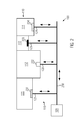
- Fig. 2 shows a further embodiment of the system 100 according to the invention.
- a main line 250 emanates from the radiator, transported in the cooling water away from the radiator and used cooling water can be transported back to the radiator.
- the return of the cooling water on another way, so not through the illustrated main line 250 occurs.
- From the main line 250 branches at several points from the already described leads 121-124. These lead the cooling water to the individual machines 111-114 and can possibly also transport them away from them.
- the individual machines 111-114 of the composite 110 have internal cooling systems 231-234.
- These internal cooling systems can be designed very differently.
- a corresponding blow molding machine 111 would comprise a cooling system 231, in which a separate cooling circuit with a large number of branches corresponding to the number of blow molds is provided.
- the heat absorbed by the cooling system can then be discharged, for example via a heat exchanger in the cooling system 231 to the cooling water, which is conveyed through the supply line 121, whereby it is removed from the single machine 111.
- a labeling machine 113 has an independent or internal air cooling system 233. Also in this an air-water heat exchanger may be provided which transfers the heat absorbed by the air cooling circuit in the labeling 113 waste heat of the components to the cooling water, which is transported in the supply line 123, whereby the removal of the cooling water through the supply line 123 Waste heat of the labeling machine is removed from this labeling machine.
- all internal cooling systems for the individual machines 111-114 are conceivable, provided that a transfer of the waste heat absorbed by these to the cooling water from the supply lines 121-124 can take place, for example, via suitable heat exchangers.
- the use of heat exchangers may or may not be required if the internal cooling system is also a water cooling system.
- the cooling circuit in the stand alone machine can either discharge the absorbed waste heat of the components to the cooling water from the water cooling circuit 115 via a heat exchanger, or the water from the water cooling circuit 115 can be used directly to cool the components of the individual machines by operating in the internal Cooling circuit is used.
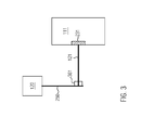
- FIG. 12 shows an embodiment of the supply of cooling water from the radiator 120 to a single machine 111, which may include a separate or internal cooling system 231.
- the supply line can, as with respect to Fig. 2 described, via a main line 250 and a branching off supply line 121 done.
- this embodiment is not mandatory, it may also be a supply line from the radiator 120 provided directly to the single machine 111, as described in relation to Fig. 1 has been described.
- a flow regulator 361 is provided which can control the flow of cooling water through the supply line 121. This includes or is connected to a controller that can evaluate data, run programs, and control the flow controller 361.
- This flow regulator 361 can be integrated either directly in the cooler 120 or in a region of the feed line, in the presence of a main line 250, preferably at the branch of the feed line 121 directly.
- the flow controller 361 may control the amount of cooling water provided to the stand alone machine 111 from the refrigeration system. This control can be based on several parameters and is generally very flexible and preferably programmable. Thus, in one embodiment it can be provided that a permanent measurement of the heat emitted by the individual components of the individual machine 111 is carried out and the need for cooling power and thus cooling water required for this purpose is calculated.
- the flow regulator 361 can then provide the amount of cooling water required for this purpose, wherein preferably losses due to the heating of the cooling water in the supply line 121 and optionally the main line 250 can be taken into account.
- the amount of cooling water to be used can be determined and thus energy-saving procedure with the cooling.
- the flow controller or the controller can also generally evaluate information about the internal cooling system, that is to say, for example, only the total cooling power that is currently provided by the latter or that taken by it Detecting the amount of heat or its cooling medium consumption and determine the required amount of cooling water, which must be supplied through the supply line of the individual machine.
- the controller or the flow controller 361 can receive sensor data from the internal cooling systems or that corresponding sensors are arranged in the individual machines, which acquire process data such as current temperature or current coolant consumption and sent to the controller of the Transmit flow controller 361.
- the control of the flow controller 361 and the individual controls of the separate cooling systems of the individual machines may be connected so that a data exchange, preferably bidirectional but in any case of the individual controllers for controlling the flow controller is possible. Either raw data or already processed data regarding the function of the individual machine in question can then be sent to the flow controller or its controller via this connection, whereupon it determines the required amount of cooling water.
- a control of the amount of cooling water provided by the flow controller 361 may also be time-dependent, for example, if it is known that certain machines are not in continuous operation but are only turned on at certain times during which they require cooling. At times when the machine is not in operation, the flow regulator 361 can completely close the supply line 121, whereby no cooling water is wasted here.
- certain "warm-up phases” in which the individual machine 111 is brought to its operating temperature and possibly already requires cooling can be taken into account. Even “decay phases”, in which the machine itself no longer processes containers, but in which it still requires cooling (in particular blow molding machines), can also be taken into account.
Landscapes
- Engineering & Computer Science (AREA)
- Physics & Mathematics (AREA)
- Mechanical Engineering (AREA)
- Thermal Sciences (AREA)
- General Engineering & Computer Science (AREA)
- Chemical & Material Sciences (AREA)
- Combustion & Propulsion (AREA)
- Devices That Are Associated With Refrigeration Equipment (AREA)
- Blow-Moulding Or Thermoforming Of Plastics Or The Like (AREA)
- Devices For Dispensing Beverages (AREA)
- Filling Of Jars Or Cans And Processes For Cleaning And Sealing Jars (AREA)
Applications Claiming Priority (1)
| Application Number | Priority Date | Filing Date | Title |
|---|---|---|---|
| DE102014100733.6A DE102014100733A1 (de) | 2014-01-23 | 2014-01-23 | Kühlsystem für Behälterbehandlungsanlagen |
Publications (3)
| Publication Number | Publication Date |
|---|---|
| EP2899480A2 true EP2899480A2 (fr) | 2015-07-29 |
| EP2899480A3 EP2899480A3 (fr) | 2015-08-19 |
| EP2899480B1 EP2899480B1 (fr) | 2018-09-19 |
Family
ID=52354773
Family Applications (1)
| Application Number | Title | Priority Date | Filing Date |
|---|---|---|---|
| EP15150817.3A Active EP2899480B1 (fr) | 2014-01-23 | 2015-01-12 | Système de refroidissement pour des installations de traitement de récipients |
Country Status (4)
| Country | Link |
|---|---|
| US (1) | US20150204616A1 (fr) |
| EP (1) | EP2899480B1 (fr) |
| CN (1) | CN104807278A (fr) |
| DE (1) | DE102014100733A1 (fr) |
Cited By (1)
| Publication number | Priority date | Publication date | Assignee | Title |
|---|---|---|---|---|
| DE102018114880A1 (de) * | 2018-06-20 | 2019-12-24 | Khs Corpoplast Gmbh | Heizvorrichtung und Blasmaschine mit Abführeinrichtung zur Abführung erwärmter Heizungsabluft und Verfahren zur thermischen Konditionierung von Blasformen |
Families Citing this family (2)
| Publication number | Priority date | Publication date | Assignee | Title |
|---|---|---|---|---|
| DE102023133922A1 (de) * | 2023-12-05 | 2025-06-05 | Khs Gmbh | Anlage zum Behandeln von Behältern |
| DE102024133247A1 (de) * | 2024-11-13 | 2026-05-13 | Krones Aktiengesellschaft | Vorrichtung und Verfahren zum Transportieren von Kunststoffvorformlingen |
Family Cites Families (19)
| Publication number | Priority date | Publication date | Assignee | Title |
|---|---|---|---|---|
| DE2148473A1 (de) * | 1971-09-29 | 1973-04-05 | Porter Lancastrian Ltd | Kuehleinrichtung |
| US5372014A (en) * | 1993-02-08 | 1994-12-13 | Perfection Equipment, Inc. | Modular cooling system for multiple spaces and dispensed beverages |
| US5501589A (en) * | 1994-04-07 | 1996-03-26 | Marcus; Paul | Injection blow molding apparatus |
| JP3203992B2 (ja) * | 1994-10-03 | 2001-09-04 | 澁谷工業株式会社 | ボトルクーラー |
| JP2000035272A (ja) * | 1998-07-16 | 2000-02-02 | Mayekawa Mfg Co Ltd | 食品の冷却設備 |
| US6212895B1 (en) * | 1999-11-19 | 2001-04-10 | Emmpak Foods Inc. | Machinery cooling system |
| BE1016119A3 (nl) * | 2004-07-14 | 2006-03-07 | Delta Engineering Bv Met Beper | Werkwijze voor het blazen van voorwerpen. |
| US20070227710A1 (en) * | 2006-04-03 | 2007-10-04 | Belady Christian L | Cooling system for electrical devices |
| DE102007003976A1 (de) * | 2007-01-26 | 2008-07-31 | Khs Ag | Pasteurisierungsvorrichtung mit integrierter Wärmepumpe und Verfahren hierzu |
| DE102007025522A1 (de) * | 2007-05-31 | 2008-12-04 | Ina-Drives & Mechatronics Gmbh & Co Ohg | Maschine mit Direktantrieb zur Behandlung von Behältern |
| DE102008056597A1 (de) * | 2008-11-10 | 2010-05-12 | Krones Ag | Heißabfüllanlage mit Wärmerückgewinnung |
| DE102008057403A1 (de) * | 2008-11-14 | 2010-05-20 | Krones Ag | Vorrichtung und Verfahren zum Herstellen von Kunststoffbehältnissen |
| DE102009005142A1 (de) * | 2009-01-15 | 2010-07-22 | Krones Ag | Streckblasmaschine mit beheizbarer Blasform |
| DE102009049150A1 (de) * | 2009-10-12 | 2011-04-28 | Krones Ag | Blasmaschine mit energieeffizienter Kühlung |
| DE102009044258A1 (de) * | 2009-10-15 | 2011-05-05 | Krones Ag | Anlage und Verfahren zur Herstellung, Abfüllung, Verpackung und/oder Transport von Getränken |
| SE1000367A1 (sv) * | 2010-04-13 | 2011-08-23 | Tetra Laval Holdings & Finance | Metod och anordning för att återvinna energi vid varmfyllning av en flytande livsmedelsprodukt |
| EP2580153B1 (fr) * | 2010-06-14 | 2015-02-11 | Conteno | Installation d'embouteillage transportable dans un conteneur |
| DE102012104275A1 (de) * | 2012-05-16 | 2013-11-21 | Krones Ag | Vorrichtung und Verfahren zum Befüllen von Behältern mit flüssigem Füllgut |
| CN202781797U (zh) * | 2012-08-27 | 2013-03-13 | 杭州特爱科塑料制品有限公司 | 一种具有降温系统的自动吹瓶机 |
-
2014
- 2014-01-23 DE DE102014100733.6A patent/DE102014100733A1/de not_active Withdrawn
-
2015
- 2015-01-12 EP EP15150817.3A patent/EP2899480B1/fr active Active
- 2015-01-21 US US14/601,281 patent/US20150204616A1/en not_active Abandoned
- 2015-01-23 CN CN201510035735.2A patent/CN104807278A/zh active Pending
Non-Patent Citations (1)
| Title |
|---|
| None |
Cited By (1)
| Publication number | Priority date | Publication date | Assignee | Title |
|---|---|---|---|---|
| DE102018114880A1 (de) * | 2018-06-20 | 2019-12-24 | Khs Corpoplast Gmbh | Heizvorrichtung und Blasmaschine mit Abführeinrichtung zur Abführung erwärmter Heizungsabluft und Verfahren zur thermischen Konditionierung von Blasformen |
Also Published As
| Publication number | Publication date |
|---|---|
| EP2899480B1 (fr) | 2018-09-19 |
| CN104807278A (zh) | 2015-07-29 |
| US20150204616A1 (en) | 2015-07-23 |
| EP2899480A3 (fr) | 2015-08-19 |
| DE102014100733A1 (de) | 2015-07-23 |
Similar Documents
| Publication | Publication Date | Title |
|---|---|---|
| EP2208606B1 (fr) | Machine de soufflage-étirage dotée d'un moule de soufflage pouvant être chauffé et son procédé de régulation de température | |
| EP2998247B1 (fr) | Installation et procédé destinés à traiter des lentilles optiques | |
| EP2383101A2 (fr) | Souffleuse | |
| EP2899480B1 (fr) | Système de refroidissement pour des installations de traitement de récipients | |
| DE102013112398A1 (de) | Verfahren sowie Anlage zum Pasteurisieren von Produkten in Behältern | |
| EP2532247A1 (fr) | Préchauffage de produit avec pompe à chaleur | |
| EP2804737B1 (fr) | Dispositif hydraulique avec dispositif de régulation de la température | |
| EP2841869B1 (fr) | Procédé permettant de fournir un réfrigérant dans un circuit secondaire | |
| EP3402722B1 (fr) | Système de traitement de récipients et procédé de changement du fonctionnement d'un système de traitement de récipients | |
| DE10351689A1 (de) | Verfahren zum Betreiben einer Pasteurisierungsanlage | |
| EP3509980A1 (fr) | Installation de remplissage permettant le traitement thermique et le remplissage d'un liquide | |
| EP3059062A1 (fr) | Dispositif de regulation de temperature variothermique ou conventionnelle d'outils de formage | |
| EP2117361B1 (fr) | Procédé de réduction de la consommation d'énergie dans des usines de pasteurisation, et installation de remplissage | |
| EP2924286B1 (fr) | Dispositif de vérification de pompes | |
| EP2657180B1 (fr) | Remplissage de produits réfrigérés | |
| WO2021013486A1 (fr) | Machine de remplissage pour remplir des contenants d'un produit de remplissage liquide, et procédé pour refroidir une unité d'entraînement et/ou de transmission d'une machine de remplissage | |
| DE102016200231A1 (de) | Behälterbehandlungsanlage zum Behandeln von Behältern | |
| EP2687351B1 (fr) | Machine de formage par soufflage dotée d'un appareil de thermorégulation interne | |
| DE102010012456A1 (de) | Anlage zur Herstellung von Formteilen | |
| DE102011079273A1 (de) | Vorrichtung und Verfahren zum Herstellen von Behältern | |
| DE102013114720A1 (de) | Verfahren zum Betreiben einer modular aufgebauten Produktionsanlage | |
| DE1767619A1 (de) | Anlage zur Erzeugung von Margarine | |
| EP4603444A1 (fr) | Alimentation froide pour une machine à laver des bouteilles | |
| DE340943C (de) | Trinkwasserbereiter | |
| EP4541554A1 (fr) | Système de fabrication de film plastique et procédé |
Legal Events
| Date | Code | Title | Description |
|---|---|---|---|
| PUAL | Search report despatched |
Free format text: ORIGINAL CODE: 0009013 |
|
| PUAI | Public reference made under article 153(3) epc to a published international application that has entered the european phase |
Free format text: ORIGINAL CODE: 0009012 |
|
| 17P | Request for examination filed |
Effective date: 20150112 |
|
| AK | Designated contracting states |
Kind code of ref document: A2 Designated state(s): AL AT BE BG CH CY CZ DE DK EE ES FI FR GB GR HR HU IE IS IT LI LT LU LV MC MK MT NL NO PL PT RO RS SE SI SK SM TR |
|
| AX | Request for extension of the european patent |
Extension state: BA ME |
|
| AK | Designated contracting states |
Kind code of ref document: A3 Designated state(s): AL AT BE BG CH CY CZ DE DK EE ES FI FR GB GR HR HU IE IS IT LI LT LU LV MC MK MT NL NO PL PT RO RS SE SI SK SM TR |
|
| AX | Request for extension of the european patent |
Extension state: BA ME |
|
| RIC1 | Information provided on ipc code assigned before grant |
Ipc: B67C 3/22 20060101ALI20150714BHEP Ipc: F25D 17/02 20060101AFI20150714BHEP |
|
| 17P | Request for examination filed |
Effective date: 20150922 |
|
| RBV | Designated contracting states (corrected) |
Designated state(s): AL AT BE BG CH CY CZ DE DK EE ES FI FR GB GR HR HU IE IS IT LI LT LU LV MC MK MT NL NO PL PT RO RS SE SI SK SM TR |
|
| STAA | Information on the status of an ep patent application or granted ep patent |
Free format text: STATUS: EXAMINATION IS IN PROGRESS |
|
| 17Q | First examination report despatched |
Effective date: 20170803 |
|
| RIC1 | Information provided on ipc code assigned before grant |
Ipc: F28D 15/00 20060101ALI20180301BHEP Ipc: B67C 3/22 20060101ALI20180301BHEP Ipc: F25D 17/02 20060101AFI20180301BHEP |
|
| GRAP | Despatch of communication of intention to grant a patent |
Free format text: ORIGINAL CODE: EPIDOSNIGR1 |
|
| STAA | Information on the status of an ep patent application or granted ep patent |
Free format text: STATUS: GRANT OF PATENT IS INTENDED |
|
| INTG | Intention to grant announced |
Effective date: 20180409 |
|
| GRAS | Grant fee paid |
Free format text: ORIGINAL CODE: EPIDOSNIGR3 |
|
| GRAA | (expected) grant |
Free format text: ORIGINAL CODE: 0009210 |
|
| STAA | Information on the status of an ep patent application or granted ep patent |
Free format text: STATUS: THE PATENT HAS BEEN GRANTED |
|
| AK | Designated contracting states |
Kind code of ref document: B1 Designated state(s): AL AT BE BG CH CY CZ DE DK EE ES FI FR GB GR HR HU IE IS IT LI LT LU LV MC MK MT NL NO PL PT RO RS SE SI SK SM TR |
|
| REG | Reference to a national code |
Ref country code: GB Ref legal event code: FG4D Free format text: NOT ENGLISH |
|
| REG | Reference to a national code |
Ref country code: CH Ref legal event code: EP |
|
| REG | Reference to a national code |
Ref country code: AT Ref legal event code: REF Ref document number: 1043711 Country of ref document: AT Kind code of ref document: T Effective date: 20181015 |
|
| REG | Reference to a national code |
Ref country code: IE Ref legal event code: FG4D Free format text: LANGUAGE OF EP DOCUMENT: GERMAN |
|
| REG | Reference to a national code |
Ref country code: DE Ref legal event code: R096 Ref document number: 502015005921 Country of ref document: DE |
|
| REG | Reference to a national code |
Ref country code: NL Ref legal event code: MP Effective date: 20180919 |
|
| PG25 | Lapsed in a contracting state [announced via postgrant information from national office to epo] |
Ref country code: FI Free format text: LAPSE BECAUSE OF FAILURE TO SUBMIT A TRANSLATION OF THE DESCRIPTION OR TO PAY THE FEE WITHIN THE PRESCRIBED TIME-LIMIT Effective date: 20180919 Ref country code: NO Free format text: LAPSE BECAUSE OF FAILURE TO SUBMIT A TRANSLATION OF THE DESCRIPTION OR TO PAY THE FEE WITHIN THE PRESCRIBED TIME-LIMIT Effective date: 20181219 Ref country code: RS Free format text: LAPSE BECAUSE OF FAILURE TO SUBMIT A TRANSLATION OF THE DESCRIPTION OR TO PAY THE FEE WITHIN THE PRESCRIBED TIME-LIMIT Effective date: 20180919 Ref country code: SE Free format text: LAPSE BECAUSE OF FAILURE TO SUBMIT A TRANSLATION OF THE DESCRIPTION OR TO PAY THE FEE WITHIN THE PRESCRIBED TIME-LIMIT Effective date: 20180919 Ref country code: LT Free format text: LAPSE BECAUSE OF FAILURE TO SUBMIT A TRANSLATION OF THE DESCRIPTION OR TO PAY THE FEE WITHIN THE PRESCRIBED TIME-LIMIT Effective date: 20180919 Ref country code: BG Free format text: LAPSE BECAUSE OF FAILURE TO SUBMIT A TRANSLATION OF THE DESCRIPTION OR TO PAY THE FEE WITHIN THE PRESCRIBED TIME-LIMIT Effective date: 20181219 Ref country code: GR Free format text: LAPSE BECAUSE OF FAILURE TO SUBMIT A TRANSLATION OF THE DESCRIPTION OR TO PAY THE FEE WITHIN THE PRESCRIBED TIME-LIMIT Effective date: 20181220 |
|
| REG | Reference to a national code |
Ref country code: LT Ref legal event code: MG4D |
|
| PG25 | Lapsed in a contracting state [announced via postgrant information from national office to epo] |
Ref country code: AL Free format text: LAPSE BECAUSE OF FAILURE TO SUBMIT A TRANSLATION OF THE DESCRIPTION OR TO PAY THE FEE WITHIN THE PRESCRIBED TIME-LIMIT Effective date: 20180919 Ref country code: LV Free format text: LAPSE BECAUSE OF FAILURE TO SUBMIT A TRANSLATION OF THE DESCRIPTION OR TO PAY THE FEE WITHIN THE PRESCRIBED TIME-LIMIT Effective date: 20180919 Ref country code: HR Free format text: LAPSE BECAUSE OF FAILURE TO SUBMIT A TRANSLATION OF THE DESCRIPTION OR TO PAY THE FEE WITHIN THE PRESCRIBED TIME-LIMIT Effective date: 20180919 |
|
| PG25 | Lapsed in a contracting state [announced via postgrant information from national office to epo] |
Ref country code: IS Free format text: LAPSE BECAUSE OF FAILURE TO SUBMIT A TRANSLATION OF THE DESCRIPTION OR TO PAY THE FEE WITHIN THE PRESCRIBED TIME-LIMIT Effective date: 20190119 Ref country code: NL Free format text: LAPSE BECAUSE OF FAILURE TO SUBMIT A TRANSLATION OF THE DESCRIPTION OR TO PAY THE FEE WITHIN THE PRESCRIBED TIME-LIMIT Effective date: 20180919 Ref country code: ES Free format text: LAPSE BECAUSE OF FAILURE TO SUBMIT A TRANSLATION OF THE DESCRIPTION OR TO PAY THE FEE WITHIN THE PRESCRIBED TIME-LIMIT Effective date: 20180919 Ref country code: PL Free format text: LAPSE BECAUSE OF FAILURE TO SUBMIT A TRANSLATION OF THE DESCRIPTION OR TO PAY THE FEE WITHIN THE PRESCRIBED TIME-LIMIT Effective date: 20180919 Ref country code: RO Free format text: LAPSE BECAUSE OF FAILURE TO SUBMIT A TRANSLATION OF THE DESCRIPTION OR TO PAY THE FEE WITHIN THE PRESCRIBED TIME-LIMIT Effective date: 20180919 Ref country code: CZ Free format text: LAPSE BECAUSE OF FAILURE TO SUBMIT A TRANSLATION OF THE DESCRIPTION OR TO PAY THE FEE WITHIN THE PRESCRIBED TIME-LIMIT Effective date: 20180919 Ref country code: EE Free format text: LAPSE BECAUSE OF FAILURE TO SUBMIT A TRANSLATION OF THE DESCRIPTION OR TO PAY THE FEE WITHIN THE PRESCRIBED TIME-LIMIT Effective date: 20180919 |
|
| PG25 | Lapsed in a contracting state [announced via postgrant information from national office to epo] |
Ref country code: SM Free format text: LAPSE BECAUSE OF FAILURE TO SUBMIT A TRANSLATION OF THE DESCRIPTION OR TO PAY THE FEE WITHIN THE PRESCRIBED TIME-LIMIT Effective date: 20180919 Ref country code: SK Free format text: LAPSE BECAUSE OF FAILURE TO SUBMIT A TRANSLATION OF THE DESCRIPTION OR TO PAY THE FEE WITHIN THE PRESCRIBED TIME-LIMIT Effective date: 20180919 Ref country code: PT Free format text: LAPSE BECAUSE OF FAILURE TO SUBMIT A TRANSLATION OF THE DESCRIPTION OR TO PAY THE FEE WITHIN THE PRESCRIBED TIME-LIMIT Effective date: 20190119 |
|
| REG | Reference to a national code |
Ref country code: DE Ref legal event code: R097 Ref document number: 502015005921 Country of ref document: DE |
|
| PLBE | No opposition filed within time limit |
Free format text: ORIGINAL CODE: 0009261 |
|
| STAA | Information on the status of an ep patent application or granted ep patent |
Free format text: STATUS: NO OPPOSITION FILED WITHIN TIME LIMIT |
|
| PG25 | Lapsed in a contracting state [announced via postgrant information from national office to epo] |
Ref country code: DK Free format text: LAPSE BECAUSE OF FAILURE TO SUBMIT A TRANSLATION OF THE DESCRIPTION OR TO PAY THE FEE WITHIN THE PRESCRIBED TIME-LIMIT Effective date: 20180919 |
|
| 26N | No opposition filed |
Effective date: 20190620 |
|
| PG25 | Lapsed in a contracting state [announced via postgrant information from national office to epo] |
Ref country code: MC Free format text: LAPSE BECAUSE OF FAILURE TO SUBMIT A TRANSLATION OF THE DESCRIPTION OR TO PAY THE FEE WITHIN THE PRESCRIBED TIME-LIMIT Effective date: 20180919 |
|
| REG | Reference to a national code |
Ref country code: CH Ref legal event code: PL |
|
| GBPC | Gb: european patent ceased through non-payment of renewal fee |
Effective date: 20190112 |
|
| PG25 | Lapsed in a contracting state [announced via postgrant information from national office to epo] |
Ref country code: LU Free format text: LAPSE BECAUSE OF NON-PAYMENT OF DUE FEES Effective date: 20190112 |
|
| REG | Reference to a national code |
Ref country code: BE Ref legal event code: MM Effective date: 20190131 |
|
| REG | Reference to a national code |
Ref country code: IE Ref legal event code: MM4A |
|
| PG25 | Lapsed in a contracting state [announced via postgrant information from national office to epo] |
Ref country code: SI Free format text: LAPSE BECAUSE OF FAILURE TO SUBMIT A TRANSLATION OF THE DESCRIPTION OR TO PAY THE FEE WITHIN THE PRESCRIBED TIME-LIMIT Effective date: 20180919 |
|
| PG25 | Lapsed in a contracting state [announced via postgrant information from national office to epo] |
Ref country code: BE Free format text: LAPSE BECAUSE OF NON-PAYMENT OF DUE FEES Effective date: 20190131 |
|
| PG25 | Lapsed in a contracting state [announced via postgrant information from national office to epo] |
Ref country code: GB Free format text: LAPSE BECAUSE OF NON-PAYMENT OF DUE FEES Effective date: 20190112 Ref country code: LI Free format text: LAPSE BECAUSE OF NON-PAYMENT OF DUE FEES Effective date: 20190131 Ref country code: CH Free format text: LAPSE BECAUSE OF NON-PAYMENT OF DUE FEES Effective date: 20190131 |
|
| PG25 | Lapsed in a contracting state [announced via postgrant information from national office to epo] |
Ref country code: IE Free format text: LAPSE BECAUSE OF NON-PAYMENT OF DUE FEES Effective date: 20190112 |
|
| PG25 | Lapsed in a contracting state [announced via postgrant information from national office to epo] |
Ref country code: TR Free format text: LAPSE BECAUSE OF FAILURE TO SUBMIT A TRANSLATION OF THE DESCRIPTION OR TO PAY THE FEE WITHIN THE PRESCRIBED TIME-LIMIT Effective date: 20180919 |
|
| PG25 | Lapsed in a contracting state [announced via postgrant information from national office to epo] |
Ref country code: MT Free format text: LAPSE BECAUSE OF FAILURE TO SUBMIT A TRANSLATION OF THE DESCRIPTION OR TO PAY THE FEE WITHIN THE PRESCRIBED TIME-LIMIT Effective date: 20180919 |
|
| REG | Reference to a national code |
Ref country code: AT Ref legal event code: MM01 Ref document number: 1043711 Country of ref document: AT Kind code of ref document: T Effective date: 20200112 |
|
| PG25 | Lapsed in a contracting state [announced via postgrant information from national office to epo] |
Ref country code: CY Free format text: LAPSE BECAUSE OF FAILURE TO SUBMIT A TRANSLATION OF THE DESCRIPTION OR TO PAY THE FEE WITHIN THE PRESCRIBED TIME-LIMIT Effective date: 20180919 Ref country code: AT Free format text: LAPSE BECAUSE OF NON-PAYMENT OF DUE FEES Effective date: 20200112 |
|
| PG25 | Lapsed in a contracting state [announced via postgrant information from national office to epo] |
Ref country code: HU Free format text: LAPSE BECAUSE OF FAILURE TO SUBMIT A TRANSLATION OF THE DESCRIPTION OR TO PAY THE FEE WITHIN THE PRESCRIBED TIME-LIMIT; INVALID AB INITIO Effective date: 20150112 |
|
| PG25 | Lapsed in a contracting state [announced via postgrant information from national office to epo] |
Ref country code: MK Free format text: LAPSE BECAUSE OF FAILURE TO SUBMIT A TRANSLATION OF THE DESCRIPTION OR TO PAY THE FEE WITHIN THE PRESCRIBED TIME-LIMIT Effective date: 20180919 |
|
| P01 | Opt-out of the competence of the unified patent court (upc) registered |
Effective date: 20230523 |
|
| PGFP | Annual fee paid to national office [announced via postgrant information from national office to epo] |
Ref country code: FR Payment date: 20251208 Year of fee payment: 12 |
|
| PGFP | Annual fee paid to national office [announced via postgrant information from national office to epo] |
Ref country code: DE Payment date: 20251203 Year of fee payment: 12 |
|
| PGFP | Annual fee paid to national office [announced via postgrant information from national office to epo] |
Ref country code: IT Payment date: 20251219 Year of fee payment: 12 |