EP2901117B1 - Prozessvariabler sender mit emf-erkennung und korrektur - Google Patents
Prozessvariabler sender mit emf-erkennung und korrektur Download PDFInfo
- Publication number
- EP2901117B1 EP2901117B1 EP13773937.1A EP13773937A EP2901117B1 EP 2901117 B1 EP2901117 B1 EP 2901117B1 EP 13773937 A EP13773937 A EP 13773937A EP 2901117 B1 EP2901117 B1 EP 2901117B1
- Authority
- EP
- European Patent Office
- Prior art keywords
- sensor
- signal
- voltage
- process variable
- preexisting
- Prior art date
- Legal status (The legal status is an assumption and is not a legal conclusion. Google has not performed a legal analysis and makes no representation as to the accuracy of the status listed.)
- Active
Links
Images



Classifications
-
- G—PHYSICS
- G01—MEASURING; TESTING
- G01K—MEASURING TEMPERATURE; MEASURING QUANTITY OF HEAT; THERMALLY-SENSITIVE ELEMENTS NOT OTHERWISE PROVIDED FOR
- G01K7/00—Measuring temperature based on the use of electric or magnetic elements directly sensitive to heat ; Power supply therefor, e.g. using thermoelectric elements
- G01K7/16—Measuring temperature based on the use of electric or magnetic elements directly sensitive to heat ; Power supply therefor, e.g. using thermoelectric elements using resistive elements
- G01K7/18—Measuring temperature based on the use of electric or magnetic elements directly sensitive to heat ; Power supply therefor, e.g. using thermoelectric elements using resistive elements the element being a linear resistance, e.g. platinum resistance thermometer
- G01K7/20—Measuring temperature based on the use of electric or magnetic elements directly sensitive to heat ; Power supply therefor, e.g. using thermoelectric elements using resistive elements the element being a linear resistance, e.g. platinum resistance thermometer in a specially-adapted circuit, e.g. bridge circuit
-
- G—PHYSICS
- G01—MEASURING; TESTING
- G01K—MEASURING TEMPERATURE; MEASURING QUANTITY OF HEAT; THERMALLY-SENSITIVE ELEMENTS NOT OTHERWISE PROVIDED FOR
- G01K7/00—Measuring temperature based on the use of electric or magnetic elements directly sensitive to heat ; Power supply therefor, e.g. using thermoelectric elements
- G01K7/02—Measuring temperature based on the use of electric or magnetic elements directly sensitive to heat ; Power supply therefor, e.g. using thermoelectric elements using thermoelectric elements, e.g. thermocouples
- G01K7/021—Particular circuit arrangements
Definitions
- the present invention relates to process variable transmitters used in process control and monitoring systems. More specifically, the present invention relates to monitoring EMF voltage across a sensor.
- Process variable transmitters are used to measure process parameters in a process control or monitoring system.
- Microprocessor-based transmitters often include a sensor, an analog-to-digital (A/D) converter for converting an output from the sensor into a digital form, a microprocessor for compensating the digitized output, and an output circuit for transmitting the compensated output.
- A/D analog-to-digital
- this transmission is normally done over a process control loop, such as a 4-20 milliamp control loop, or wirelessly.
- Temperature is sensed by measuring the resistance of a restive temperature device (RTD), which is also sometimes called a platinum resistance thermometer (or PRT), or the voltage output from a thermocouple.
- RTD restive temperature device
- PRT platinum resistance thermometer
- temperature is only one exemplary process variable and a wide variety of other process control parameters can be measured as well, including, for example, pH, pressure, flow, etc. Therefore, while the present discussion proceeds with respect to a temperature sensor, it will be appreciated that the discussion could just as easily proceed with respect to sensing of other parameters.
- connection points between a temperature sensor and a measurement transmitter There are a number of connection points between a temperature sensor and a measurement transmitter, that can fail or become degraded.
- connection points or measurement lines have elevated levels of resistance, small currents can be induced on these connection points or lines that impact the sensor measurement accuracy.
- the sensor connection points and measurement lines can become degraded, and thus exhibit these elevated levels of resistance, due to wire fraying, corrosion, or the connections can just become loose.
- small voltages across the temperature sensor or in the measurement loop can begin to form, and can be sensitive to temperature changes. These voltages can create measurement inaccuracies.
- a resistive temperature detector (or RTD) ohmic measurement is generated by using up to six individual voltage points on a ratiometric calculation. All of these measurements take approximately 60 milliseconds to collect.
- RTD resistive temperature detector
- V emf In order to obtain the value of V emf , up to two 60 millisecond voltage measurements are taken per sensor, when no excitation current is induced across the RTD. These measurements represent thermal voltages that can be induced on the sensor wires due to fraying, corrosion, or loose connections, among other things. These measurements can be subtracted in software from the voltage drop measured across the RTD when the excitation current is present. US Patent No. 6,356,191 is directed to this process, and the process works quite well.
- US 5,563,587 discloses a transmitter which includes a sensor for sensing a primary process variable representative of a process, and provides a sensor output current.
- An integrator in the transmitter integrates the sensor output current.
- the integrator has an amplifier on an integrated circuit and an off-chip capacitor coupled between the inverting input on the amplifier and the amplifier output via two integrated circuit pads, which leak undesirable leakage current to the integrator.
- a leakage cancellation circuit is selectively connectable to the inverting input of the amplifier in the integrator, the cancellation circuit providing a current substantially opposite in polarity and equal in magnitude to the leakage current as a function of a stored voltage representative of the magnitude of the leakage current.
- US 6,356,191 discloses a process fluid temperature transmitter which includes a circuitry that improves compensation of error due to the presence of one or more non-associated voltage sources in a resistance temperature device (RTD) circuit.
- RTD resistance temperature device
- V emf it takes time to collect the measurements for V emf .
- the time to collect the V emf measurements is approximately 120 milliseconds per sensor. This can negatively affect the update rate on a temperature transmitter.
- a differential voltage is used to measure a parameter of a sensor which is related to a process variable.
- a preexisting voltage across a sensor is latched to a storage capacitor.
- the latched voltage on the storage capacitor is subtracted from the differential voltage across the sensor.
- the subtraction is done before a measurement is converted to a digital value. This reduces inaccuracies in the measurement of the differential voltage.
- FIG. 1 is a simplified diagram of an industrial process control system 5.
- process piping 7 carries a process fluid.
- a process variable transmitter 10 is configured to couple to the process piping 7.
- Transmitter 10 includes a process variable sensor 18 which, in one embodiment, comprises a resistive temperature device or other temperature sensor.
- sensor 18 could be any of a wide variety of other sensors, including a flow sensor, a pH sensor, a pressure sensor, etc.
- Transmitter 10 transmits information to a remote location, such as a process control room 6.
- the transmission can be over a process control loop such as a two-wire control loop 11.
- the process control loop can be in accordance with any desired format, including, for example, a 4-20 milliamp process control loop, a process control loop which carries digital communications, a wireless process control loop, etc.
- the process control loop 11 is powered by a power supply 6A at control room 6. This power is used to provide power to the process variable transmitter 10.
- Sense resistor 6B can be used to sense the current flowing through loop 11, although other mechanisms can be used as well.
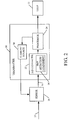
- FIG. 2 is a block diagram of a portion of industrial process control system 5, shown in FIG. 1 , and transmitter 10 is shown in greater detail.
- sensor 18 is illustratively a process variable transmitter that receives input 14 from a process being sensed.
- the input is illustratively the process fluid flowing through piping 7, and sensor 18 is illustratively a temperature sensor, such as a resistive temperature device.
- Sensor 18 illustratively provides an analog output 20, indicative of the sensed parameter (e.g., temperature), to A/D converter 22 in transmitter 10.
- the output 20 from sensor 18 can illustratively be provided to a circuit (not shown in FIG. 2 ) that amplifies and filters the analog signal, as appropriate. This can be part of sensor 18, or transmitter 10 or a separate circuit. In any case, the amplified and filtered signal 20 is then provided to A/D converter 22. A/D converter 22 provides a digitized output to processor 24, which is a digital representation of the analog signal 20 provided by sensor 18.
- Processor 24 includes associated memory and clock circuitry and provides information regarding the sensed parameter over process control loop 11. It should be noted that processor 24 can include an input/output (I/O circuit), or an I/O circuit can be provided separately, that transmits information in a digital format on loop 11, or in an analog format by controlling current flow though loop 11. Thus, the information related to the sensed parameter is provided over process control loop 11 by transmitter 10. Processor 24 is shown in this embodiment as being separate from A/D converter 22. However, it could be included in A/D converter 22, or A/D converter 22 can have its own state machine or processor, separate from processor 24, controlling other parts of A/D converter 22 and controlling EMF compensation as discussed below. The present description is provided by way of example only.
- FIG. 2 also shows that transmitter 10 includes current source 30 that is controlled by processor 24.
- Current source 30 can provide excitation current (also referred to as a control signal), as needed, to sensor 18.
- excitation current also referred to as a control signal
- sensor 18 is a resistive temperature device
- current source 30 provides an excitation current across the resistive temperature device so that the voltage across the resistive temperature device can be used to provide the output 20 indicative of the sensed temperature of the fluid.
- A/D converter 22 includes EMF detection component 26.
- EMF detection component 26 detects an EMF voltage preexisting on the sensor 18 prior to application of the excitation current.
- Component 26 can be either internal or external to A/D converter 22. It is shown internal to A/D converter 22 in the example shown in FIG. 2 , but this is by way of example only.
- EMF detection component 26 provides an output indicative of the level of the detected preexisting EMF voltage to processor 24, and it is also configured to subtract the preexisting EMF voltage from the voltage in signal 20 when the excitation current is applied, in order to correct signal 20 for the preexisting EMF voltage.
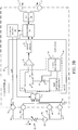
- FIG. 3A is a more detailed diagram of transmitter 10, and similar items are numbered the same as in FIG. 2 .
- FIG. 3A also specifically shows more detail for A/D converter 22 and EMF detection component 26.
- A/D converter 22 illustratively includes differential amplifier 32 and a sigma delta converter 34.
- sigma delta converter 34 is shown by way of example only and other conversion mechanisms can be used as well.
- FIG. 3A also shows that EMF detection component 26 illustratively includes level detector 26, switches SI, S2 and S3, and capacitor C1.
- FIG. 3A shows that sensor 18 has two leads 38 and 40 which can be coupled to input terminals 42 and 44, respectively.
- the voltage across terminals 42 and 44 is indicative of the temperature sensed by sensor 18, in addition to the EMF voltage represented by voltage source 46.
- Sensor 18 can illustratively be a four lead sensor with two additional leads coupled to two additional terminals, respectively. This is shown in greater detail with respect to FIG. 3B described below. However, for the sake of the present example, the description will proceed with respect to sensor 18 having two leads connected to terminals 42 and 44.
- EMF detection component 26 A more detailed operation of EMF detection component 26 is described below with respect to FIG. 4 . Briefly, however, the voltage across terminals 42 and 44 is first latched across capacitor C1, before the excitation current I rtd is provided across sensor 18. This effectively causes storage capacitor C1 to store the preexisting voltage on sensor 18 (i.e., the EMF voltage 46). Then, switch S2 is opened and switches S1 and S3 are closed. Processor 24 controls current source 30 to apply excitation current I rtd across sensor 18 to develop a voltage across sensor 18 to take a temperature measurement. This circuit configuration operates to subtract the voltage on capacitor C1 from the voltage across terminals 42 and 44, before it is input to differential amplifier 32.
- level detector 36 detects the voltage level across capacitor C1, which is indicative of EMF voltage 46.
- Level detector 36 in one embodiment, is a comparator that compares the EMF voltage to one or more thresholds that can be set empirically or otherwise. If the EMF voltage exceeds any of the thresholds, detector 36 outputs an indication of this to processor 24. Processor 24 can then determine whether the EMF voltage is excessive and requires further action.
- differential amplifier 32 provides an output to sigma delta converter 34 that is indicative of the voltage across sensor 18, but not EMF voltage 46, because that has been subtracted from the voltage across terminals 42 and 44.
- the output from level detector 36, and the output from converter 34, are provided to processor 24 for further processing.
- FIG. 4 illustrates the operation of transmitter 10 in more detail. The operation of transmitter 10 will now be described with respect to FIGS. 2 , 3A and 4 in conjunction with one another.
- Processor 24 first provides a control signal to close switch S2 and open switches S1 and S3. This is indicated by block 80 in FIG. 4 , and it is done before processor 24 controls current source 30 to apply the excitation current I rtd across resistor 18. Therefore, this has the effect of latching the preexisting EMF voltage across storage capacitor C1. This is indicated by block 82 in FIG. 4 .
- Processor 24 then opens switch S2 and closes switches S1 and S3. This is indicated by block 84 in FIG. 4 . Processor 24 then turns on current source 30 to apply excitation current I rtd across sensor 18. This is indicated by block 86 in FIG. 4 .
- Capacitor C1 acts to subtract the EMF voltage from that input voltage, so that the voltage applied to the inputs of differential amplifier 32 (across terminal 42 and node 60) is substantially only the voltage across sensor 18. Subtracting the EMF voltage from the sensor input voltage at the input of the differential amplifier 32 is indicated by block 88 in FIG. 4 .
- the differential amplifier 32 then provides an input to sigma delta converter 34 that is indicative of a measurement of the voltage across sensor 18. This is indicated by block 90 in FIG. 4 .
- Converter 34 then digitizes the measurement signal output by differential amplifier 32 and provides a digital representation of the sensor voltage to processor 24. This is indicated by block 92 in FIG. 4 .
- Level detector 36 detects the voltage level across capacitor C1, which is substantially equivalent to EMF voltage 46. As discussed above, this can be done by comparing the EMF voltage on capacitor C1 to one or more thresholds. Of course, it can be digitized as well. Detecting the EMF voltage level is indicated by block 94 in FIG. 4 .
- the EMF voltage level is provided to processor 24 so that processor 24 can determine whether the EMF voltage is high enough to indicate a warning condition, or other problem that the user should be made aware of. For instance, when the voltage level exceeds a predetermined threshold value, this can indicate undue wear or corrosion of leads 38 and 40, or it can indicate a loose connection at one of terminals 42 and 44, or it can indicate fraying or corrosion of wires used to connect sensor 18 to A/D converter 22, or any of a wide variety of other conditions. For instance, there may also be thermocouple junctions at connection points that add to the EMF voltage when exposed to thermal gradients. This will be captured in the EMF voltage 46 as well.
- the particular voltage threshold can be set empirically or otherwise, and more than one can be set as well. In one embodiment, it is set to approximately +/- 12mV, although any other desired voltage level can be used as well. Detecting whether the EMF voltage level is excessive is indicated by block 96 in FIG. 4 .
- processor 24 determines that the EMF voltage level is excessive, it generates an excessive EMF indicator, that can be detectable by the user, so the user knows of the condition. This is indicated by block 98 in FIG. 4 . In one embodiment, for instance, processor 24 simply sets a status bit to indicate that the EMF voltage is excessive, and that information is transmitted to control room 6 using loop 11. Of course, other types of indicators can be used as well.
- FIG. 3A shows that sensor 18 is only connected to terminals 42 and 44, this is exemplary only.
- FIG. 3B shows an embodiment in which sensor 18 is a four lead sensor with additional leads 48 and 50 coupled to terminals 52 and 54, respectively.
- the excitation current I rtd is applied from current source 30 at terminal 52 and lead 50 to sensor 18.
- Processor 24 controls multiplexor 53, which receives inputs from terminals 42, 44, 52 and 54 so the desired voltages are input to differential amplifier 32 and EMF detection component 26.
- the voltage drop in the connections to terminals 42 and 44 can largely be eliminated because substantially all of the excitation current I rtd flows between terminals 52 and 54 and across resistor R1. This improves accuracy.
- there still may be undesired preexisting voltage 46 in the circuit and this can be detected and compensated for as set out above with respect to FIGS. 3A and 4 .
- thermocouple or other voltage sensor
- there will be a voltage from the sensor but resistance will also be present on the sensor loop due to the high resistivity of the wires and junctions connecting to the sensor.
- this resistance can indicate some type of degrading condition such as those mentioned above in the other embodiment.
- the resistance on the sensor loop can be measured by applying an excitation current in the same way as the resistance of an RTD is sensed.
- the thermocouple (or other sensor) voltage is compensated for (like the preexisting EMF voltage 46 discussed above) to obtain a measure of the loop resistance. This can be done intermittently to monitor the loop resistance.
- the present system automatically compensates for residual (preexisting) EMF voltage that exists on any of the measurement lines or terminals in the system. While it is described with respect to a resistive temperature device, it can be applied to thermocouples as well in order to measure their loop resistance. Of course, it can be applied to other sensors to sense other parameters and temperature is described by way of example only. It can also be seen that the compensation is done in hardware, very quickly, prior to digitizing the sensor measurement. Thus, it can be performed well within the normal settling time of a measurement circuit.
Landscapes
- Physics & Mathematics (AREA)
- General Physics & Mathematics (AREA)
- Arrangements For Transmission Of Measured Signals (AREA)
- Measuring Volume Flow (AREA)
Claims (16)
- Prozessvariablentransmitter (10), der aufweist:einen Analog-Digital-(A/D)-Wandler (22), der eingerichtet ist, ein Sensorsignal (20) von einem Sensor (18) zu empfangen, das eine abgetastete Prozessvariable anzeigt, wobei der A/D-Wandler (22) das Sensorsignal (20) in ein Digitalsignal umwandelt;einen Prozessor (24), der eingerichtet ist, ein Steuersignal an den Sensor (18) zu liefern und das Digitalsignal zu empfangen und eine Messausgabe bereitzustellen, die das Digitalsignal anzeigt; undeine Detektionskomponente (26), die eingerichtet ist, eine Eingabe zu empfangen, die vorher am Sensor (18) vorhanden ist, bevor der Prozessor (24) das Steuersignal an den Sensor (18) liefert, und ein Detektionssignal an den Prozessor (24) zu liefern, das einen Pegel der vorher vorhandenen Eingabe anzeigt,wobei das Sensorsignal (20) eine Spannung aufweist, die die abgetastete Prozessvariable anzeigt, und wobei die Detektionskomponente (26) eingerichtet ist, die vorher vorhandene Eingabe als eine vorher vorhandene Spannung in der vorher vorhandenen Eingabe zu detektieren;wobei die Detektionskomponente (26) eingerichtet ist, die vorher vorhandene Spannung zu kompensieren, bevor der A/D-Wandler (22) das Sensorsignal empfängt, so dass das durch den A/D-Wandler (22) empfangene Sensorsignal (20) das kompensierte Sensorsignal aufweist.
- Prozessvariablentransmitter nach Anspruch 1, der ferner aufweist:
eine Stromquelle (30), die steuerbar mit dem Prozessor (24) gekoppelt ist, um das Steuersignal an den Sensor (18) als einen Steuerstrom zu liefern. - Prozessvariablentransmitter nach Anspruch 2, wobei der Sensor eine widerstandsbehaftete Temperaturvorrichtung aufweist und wobei der Steuerstrom einen Anregungsstrom aufweist, der an die widerstandsbehaftete Temperaturvorrichtung angelegt wird, um eine Spannung zu erhalten, die eine abgetastete Temperatur anzeigt.
- Prozessvariablentransmitter nach Anspruch 3, wobei die Detektionskomponente (26) eingerichtet ist, die vorher vorhandene Spannung zu speichern und die vorher vorhandene Spannung im Sensorsignal (20) zu kompensieren, um ein kompensiertes Sensorsignal zu erhalten.
- Prozessvariablentransmitter nach Anspruch 1, wobei die Detektionskomponente eingerichtet ist, das Sensorsignal durch Subtrahieren der vorher vorhandenen Spannung vom Sensorsignal zu kompensieren, um das kompensierte Sensorsignal zu erhalten, wobei die Subtraktion vorzugsweise durch Hardwarekomponenten (32) durchgeführt wird.
- Prozessvariablentransmitter nach Anspruch 5, wobei die Detektionskomponente (26) eingerichtet ist, die vorher vorhandene Spannung in einem Speicherkondensator (Cl) zu speichern, und wobei der Speicherkondensator (Cl), wenn er im Gebrauch ist, an einen Eingang in den A/D-Wandler geschaltet wird, um die vorher vorhandene Spannung vom Sensorsignal am Eingang in den A/D-Wandler zu subtrahieren.
- Prozessvariablentransmitter nach Anspruch 4, wobei der A/D-Wandler einen Differenzverstärker (32) aufweist, der mit einem A/D-Umwandlungsmechanismus gekoppelt ist, und wobei die Detektionskomponente (26) eingerichtet ist, das Sensorsignal (20) an einem Eingang in den Differenzverstärker (32) zu kompensieren.
- Prozessvariablentransmitter nach Anspruch 7, wobei die Detektionskomponente (26) eingerichtet ist, das Detektionssignal an den Prozessor (24) zu liefern, das einen Pegel der vorher vorhandenen Spannung anzeigt, und wobei der Prozessor (24) eingerichtet ist, eine Ausgabe zu liefern, die anzeigt, dass die vorher vorhandene Spannung übermäßig ist, wenn die vorher vorhandene Spannung eine vorgegebene Schwellenspannung überschreitet, wobei der Prozessor (24) vorzugsweise eingerichtet ist, die Ausgabe über einen Regelkreis (11) zu liefern, wobei der Regelkreis vorzugsweise einen 4-20 mA-Regelkreis aufweist.
- Prozessvariablentransmitter nach Anspruch 1, wobei der A/D-Wandler eingerichtet ist, das Sensorsignal von einem Thermoelement zu empfangen.
- Prozessvariablentransmitter nach Anspruch 1, wobeii) der Prozessor (24) Teil des A/D-Wandlers ist, oderii) der Prozessor (24) einen ersten Prozessor, der vom A/D-Wandler getrennt ist, und einen zweiten Prozessor aufweist, der Teil des A/D Wandlers ist.
- Verfahren zum Abtasten einer Prozessvariable in einem Prozesssteuersystem, das einen Prozessvariablentransmitter nach einem der Ansprüche 1 bis 10 aufweist, wobei das Verfahren aufweist:Liefern des Steuersignals an den Sensor (18), um an einem Sensoreingang das Sensorsignal (20) vom Sensor (18) zu erhalten, das die Prozessvariable anzeigt;Umwandeln des Sensorsignals (20) von einem Analogsignal in ein Digitalsignal;Liefern einer Ausgabe an einen Prozessregelkreis, die das Digitalsignal anzeigt;vor dem Liefern des Steuersignals, Detektieren des vorher vorhandenen Spannungspegels am Sensoreingang; undnach dem Liefern des Steuersignals, Kompensieren des vorher vorhandenen Spannungspegels im Sensorsignal (20), bevor das Sensorsignal in das Digitalsignal umgewandelt wird.
- Verfahren nach Anspruch 11, das ferner aufweist:Detektieren, ob der vorher vorhandene Spannungspegel einen vorgegebenen Schwellenpegel überschreitet; undfalls ja, Bereitstellen der Ausgabe am Prozessregelkreis, um anzuzeigen, dass der vorher vorhandene Spannungspegel den vorgegebenen Schwellenpegel überschreitet.
- Verfahren nach Anspruch 12, wobei der Sensor eine widerstandsbehaftete Vorrichtung aufweist und wobei das Liefern des Steuersignals aufweist:
Liefern eines Anregungsstroms an die widerstandsbehaftete Vorrichtung. - Verfahren nach Anspruch 13, wobei das Umwandeln des Sensorsignals durch eine Messschaltung durchgeführt wird, wobei das Kompensieren aufweist:Speichern der vorher vorhandenen Spannung in einem Kondensator vor dem Liefern des Anregungsstroms; undSchalten des Kondensators in die Messschaltung, um die vorher vorhandene Spannung vor dem Umwandeln der Sensorspannung in das Digitalsignal von der Sensorspannung zu subtrahieren.
- Prozesssteuersystem, das aufweist:einen Sensor (18), der eine Prozessvariable abtastet und ein analoges Sensorsignal bereitstellt, das die abgetastete Prozessvariable anzeigt, wobei der Sensor (18) steuerbar ist, ein Steuersignal zu empfangen und als Reaktion auf das Steuersignal das analoge Sensorsignal abzugeben; undeinen Prozessvariablentransmitter nach einem der Ansprüche 1 bis 10.
- Prozesssteuersystem nach Anspruch 15, wobei der Sensor einen Temperatursensor aufweist und wobei das Steuersignal einen Anregungsstrom für den Temperatursensor aufweist.
Applications Claiming Priority (2)
| Application Number | Priority Date | Filing Date | Title |
|---|---|---|---|
| US13/629,127 US9207129B2 (en) | 2012-09-27 | 2012-09-27 | Process variable transmitter with EMF detection and correction |
| PCT/US2013/060313 WO2014052110A2 (en) | 2012-09-27 | 2013-09-18 | Process variable transmitter with emf detection and correction |
Publications (2)
| Publication Number | Publication Date |
|---|---|
| EP2901117A2 EP2901117A2 (de) | 2015-08-05 |
| EP2901117B1 true EP2901117B1 (de) | 2018-08-22 |
Family
ID=49074673
Family Applications (1)
| Application Number | Title | Priority Date | Filing Date |
|---|---|---|---|
| EP13773937.1A Active EP2901117B1 (de) | 2012-09-27 | 2013-09-18 | Prozessvariabler sender mit emf-erkennung und korrektur |
Country Status (5)
| Country | Link |
|---|---|
| US (1) | US9207129B2 (de) |
| EP (1) | EP2901117B1 (de) |
| JP (1) | JP6014769B2 (de) |
| CN (2) | CN103698040B (de) |
| WO (1) | WO2014052110A2 (de) |
Families Citing this family (8)
| Publication number | Priority date | Publication date | Assignee | Title |
|---|---|---|---|---|
| US9207129B2 (en) * | 2012-09-27 | 2015-12-08 | Rosemount Inc. | Process variable transmitter with EMF detection and correction |
| US9222844B2 (en) * | 2013-02-25 | 2015-12-29 | Rosemount Inc. | Process temperature transmitter with improved sensor diagnostics |
| US9470580B2 (en) * | 2013-09-26 | 2016-10-18 | Rosemount Inc. | Infrared sensor |
| EP3486627B1 (de) * | 2017-11-15 | 2022-07-27 | Melexis Technologies NV | Fehlerkompensation für ummantelte sensoren |
| US11566948B2 (en) * | 2020-02-13 | 2023-01-31 | Honeywell International Inc. | Enhancing RTD measurement accuracy by means of variable excitation current |
| US20220166762A1 (en) * | 2020-11-25 | 2022-05-26 | Microsoft Technology Licensing, Llc | Integrated circuit for obtaining enhanced privileges for a network-based resource and performing actions in accordance therewith |
| CN113899461B (zh) * | 2021-09-27 | 2025-03-14 | 山东阿恩曼智能科技有限公司 | 一种智能温度变送器及测量方法 |
| US12200888B2 (en) * | 2022-02-01 | 2025-01-14 | Rosemount Inc. | Customization of process variable transmitter with hermetically sealed electronics |
Family Cites Families (216)
| Publication number | Priority date | Publication date | Assignee | Title |
|---|---|---|---|---|
| NL272090A (de) | 1960-12-02 | |||
| US3096434A (en) | 1961-11-28 | 1963-07-02 | Daniel Orifice Fitting Company | Multiple integration flow computer |
| US3404264A (en) | 1965-07-19 | 1968-10-01 | American Meter Co | Telemetering system for determining rate of flow |
| US3468164A (en) | 1966-08-26 | 1969-09-23 | Westinghouse Electric Corp | Open thermocouple detection apparatus |
| US3590370A (en) | 1969-04-09 | 1971-06-29 | Leeds & Northrup Co | Method and apparatus for detecting the open-circuit condition of a thermocouple by sending a pulse through the thermocouple and a reactive element in series |
| US3701280A (en) | 1970-03-18 | 1972-10-31 | Daniel Ind Inc | Method and apparatus for determining the supercompressibility factor of natural gas |
| US3691842A (en) | 1970-09-08 | 1972-09-19 | Beckman Instruments Inc | Differential pressure transducer |
| US3688190A (en) | 1970-09-25 | 1972-08-29 | Beckman Instruments Inc | Differential capacitance circuitry for differential pressure measuring instruments |
| USRE29383E (en) | 1974-01-10 | 1977-09-06 | Process Systems, Inc. | Digital fluid flow rate measurement or control system |
| US3872389A (en) | 1974-02-12 | 1975-03-18 | Westinghouse Electric Corp | Signal processor |
| US3973184A (en) | 1975-01-27 | 1976-08-03 | Leeds & Northrup Company | Thermocouple circuit detector for simultaneous analog trend recording and analog to digital conversion |
| GB1534280A (en) | 1975-02-28 | 1978-11-29 | Solartron Electronic Group | Method and apparatus for testing thermocouples |
| US4058975A (en) | 1975-12-08 | 1977-11-22 | General Electric Company | Gas turbine temperature sensor validation apparatus and method |
| US4099413A (en) | 1976-06-25 | 1978-07-11 | Yokogawa Electric Works, Ltd. | Thermal noise thermometer |
| US4102199A (en) | 1976-08-26 | 1978-07-25 | Megasystems, Inc. | RTD measurement system |
| US4122719A (en) | 1977-07-08 | 1978-10-31 | Environmental Systems Corporation | System for accurate measurement of temperature |
| US4250490A (en) | 1979-01-19 | 1981-02-10 | Rosemount Inc. | Two wire transmitter for converting a varying signal from a remote reactance sensor to a DC current signal |
| US4279151A (en) | 1979-08-07 | 1981-07-21 | Bethlehem Steel Corporation | Temperature measuring system |
| US4337516A (en) | 1980-06-26 | 1982-06-29 | United Technologies Corporation | Sensor fault detection by activity monitoring |
| JPS5829096A (ja) * | 1981-08-13 | 1983-02-21 | 株式会社東芝 | プロセス変数伝送器 |
| US4399824A (en) | 1981-10-05 | 1983-08-23 | Air-Shields, Inc. | Apparatus for detecting probe dislodgement |
| JPS58129316A (ja) | 1982-01-29 | 1983-08-02 | Mitsubishi Heavy Ind Ltd | 検出器異常診断装置 |
| US4475823A (en) | 1982-04-09 | 1984-10-09 | Piezo Electric Products, Inc. | Self-calibrating thermometer |
| US4571689A (en) | 1982-10-20 | 1986-02-18 | The United States Of America As Represented By The Secretary Of The Air Force | Multiple thermocouple testing device |
| JPS59116811A (ja) | 1982-12-24 | 1984-07-05 | Hitachi Ltd | 入力異常診断方法 |
| US4565456A (en) | 1983-04-13 | 1986-01-21 | Omron Tateisi Electronics Co. | Electronic thermometer |
| JPS59211896A (ja) | 1983-05-17 | 1984-11-30 | 三菱重工業株式会社 | 検出器応答異常診断装置 |
| JPS59211196A (ja) | 1983-05-17 | 1984-11-29 | 三菱重工業株式会社 | 検出器応答異常診断装置 |
| JPS60507A (ja) | 1983-06-17 | 1985-01-05 | Hitachi Ltd | プロセス診断方式 |
| US4530234A (en) | 1983-06-30 | 1985-07-23 | Mobil Oil Corporation | Method and system for measuring properties of fluids |
| JPH0619666B2 (ja) | 1983-06-30 | 1994-03-16 | 富士通株式会社 | 故障診断処理方式 |
| JPS6076619A (ja) | 1983-10-03 | 1985-05-01 | Mitsubishi Heavy Ind Ltd | 検出器応答異常診断装置 |
| US4707796A (en) | 1983-10-19 | 1987-11-17 | Calabro Salvatore R | Reliability and maintainability indicator |
| JPS60131495A (ja) | 1983-12-20 | 1985-07-13 | 三菱重工業株式会社 | 検出器異常診断装置 |
| US4517468A (en) | 1984-04-30 | 1985-05-14 | Westinghouse Electric Corp. | Diagnostic system and method |
| US4649515A (en) | 1984-04-30 | 1987-03-10 | Westinghouse Electric Corp. | Methods and apparatus for system fault diagnosis and control |
| US4644479A (en) | 1984-07-31 | 1987-02-17 | Westinghouse Electric Corp. | Diagnostic apparatus |
| US4642782A (en) | 1984-07-31 | 1987-02-10 | Westinghouse Electric Corp. | Rule based diagnostic system with dynamic alteration capability |
| JPH0734162B2 (ja) | 1985-02-06 | 1995-04-12 | 株式会社日立製作所 | 類推制御方法 |
| JPH079680B2 (ja) | 1985-04-01 | 1995-02-01 | ホーチキ株式会社 | アナログ火災報知装置 |
| JPS6230915A (ja) | 1985-08-02 | 1987-02-09 | Mitsubishi Heavy Ind Ltd | 応答異常診断装置 |
| US5179540A (en) | 1985-11-08 | 1993-01-12 | Harris Corporation | Programmable chip enable logic function |
| DE3540204C1 (de) | 1985-11-13 | 1986-09-25 | Daimler-Benz Ag, 7000 Stuttgart | Vorrichtung in einem Kraftfahrzeug zur Anzeige der Aussentemperatur |
| JPS6340825A (ja) | 1986-08-07 | 1988-02-22 | Terumo Corp | 電子体温計 |
| US4783659A (en) | 1986-08-22 | 1988-11-08 | Rosemount Inc. | Analog transducer circuit with digital control |
| US4736367A (en) | 1986-12-22 | 1988-04-05 | Chrysler Motors Corporation | Smart control and sensor devices single wire bus multiplex system |
| US5005142A (en) | 1987-01-30 | 1991-04-02 | Westinghouse Electric Corp. | Smart sensor system for diagnostic monitoring |
| EP0308455B1 (de) | 1987-04-02 | 1993-01-27 | Eftag Entstaubungs- Und Fördertechnik Ag | Schaltungsanordnung zur auswertung der von einem halbleitergassensor erzeugten signale |
| US5319576A (en) | 1987-08-05 | 1994-06-07 | General Signal Corporation | Wireless data gathering system for molten metal processing |
| US4988990A (en) | 1989-05-09 | 1991-01-29 | Rosemount Inc. | Dual master implied token communication system |
| US5122794A (en) | 1987-08-11 | 1992-06-16 | Rosemount Inc. | Dual master implied token communication system |
| US4873655A (en) | 1987-08-21 | 1989-10-10 | Board Of Regents, The University Of Texas System | Sensor conditioning method and apparatus |
| US4907167A (en) | 1987-09-30 | 1990-03-06 | E. I. Du Pont De Nemours And Company | Process control system with action logging |
| US4831564A (en) | 1987-10-22 | 1989-05-16 | Suga Test Instruments Co., Ltd. | Apparatus for estimating and displaying remainder of lifetime of xenon lamps |
| US5274572A (en) | 1987-12-02 | 1993-12-28 | Schlumberger Technology Corporation | Method and apparatus for knowledge-based signal monitoring and analysis |
| US5488697A (en) | 1988-01-12 | 1996-01-30 | Honeywell Inc. | Problem state monitoring system |
| US5193143A (en) | 1988-01-12 | 1993-03-09 | Honeywell Inc. | Problem state monitoring |
| US4841286A (en) | 1988-02-08 | 1989-06-20 | Honeywell Inc. | Apparatus and method for detection of an open thermocouple in a process control network |
| US4924418A (en) | 1988-02-10 | 1990-05-08 | Dickey-John Corporation | Universal monitor |
| JPH0774961B2 (ja) | 1988-04-07 | 1995-08-09 | 株式会社日立製作所 | オートチユーニングpid調節計 |
| US4882564A (en) | 1988-06-06 | 1989-11-21 | Monitech Corporation | Remote temperature monitoring system |
| US4964125A (en) | 1988-08-19 | 1990-10-16 | Hughes Aircraft Company | Method and apparatus for diagnosing faults |
| US5197328A (en) | 1988-08-25 | 1993-03-30 | Fisher Controls International, Inc. | Diagnostic apparatus and method for fluid control valves |
| US5268311A (en) | 1988-09-01 | 1993-12-07 | International Business Machines Corporation | Method for forming a thin dielectric layer on a substrate |
| US5099436A (en) | 1988-11-03 | 1992-03-24 | Allied-Signal Inc. | Methods and apparatus for performing system fault diagnosis |
| US5067099A (en) | 1988-11-03 | 1991-11-19 | Allied-Signal Inc. | Methods and apparatus for monitoring system performance |
| EP0369489A3 (de) | 1988-11-18 | 1991-11-27 | Omron Corporation | Steuerungssystem für Sensoren |
| JP2714091B2 (ja) | 1989-01-09 | 1998-02-16 | 株式会社日立製作所 | フィールド計器 |
| US5098197A (en) | 1989-01-30 | 1992-03-24 | The United States Of America As Represented By The United States Department Of Energy | Optical Johnson noise thermometry |
| US5081598A (en) | 1989-02-21 | 1992-01-14 | Westinghouse Electric Corp. | Method for associating text in automatic diagnostic system to produce recommended actions automatically |
| US4939753A (en) | 1989-02-24 | 1990-07-03 | Rosemount Inc. | Time synchronization of control networks |
| DE4008560C2 (de) | 1989-03-17 | 1995-11-02 | Hitachi Ltd | Verfahren und Vorrichtung zum Bestimmen einer Restlebensdauer eines Aggregats |
| JPH0692914B2 (ja) | 1989-04-14 | 1994-11-16 | 株式会社日立製作所 | 機器/設備の状態診断システム |
| US5089984A (en) | 1989-05-15 | 1992-02-18 | Allen-Bradley Company, Inc. | Adaptive alarm controller changes multiple inputs to industrial controller in order for state word to conform with stored state word |
| US5051743A (en) | 1989-05-31 | 1991-09-24 | Ball Corporation | High precision, high frequency current sensing and analog signal decoding network |
| US4934196A (en) | 1989-06-02 | 1990-06-19 | Micro Motion, Inc. | Coriolis mass flow rate meter having a substantially increased noise immunity |
| JPH0650557B2 (ja) | 1989-07-04 | 1994-06-29 | 株式会社日立製作所 | フィールド計器の通信方式 |
| US5293585A (en) | 1989-08-31 | 1994-03-08 | Kabushiki Kaisha Toshiba | Industrial expert system |
| JP2656637B2 (ja) | 1989-11-22 | 1997-09-24 | 株式会社日立製作所 | プロセス制御システム及び発電プラントプロセス制御システム |
| JPH03166601A (ja) | 1989-11-27 | 1991-07-18 | Hitachi Ltd | 制御支援装置 |
| CA2031765C (en) | 1989-12-08 | 1996-02-20 | Masahide Nomura | Method and system for performing control conforming with characteristics of controlled system |
| US5111531A (en) | 1990-01-08 | 1992-05-05 | Automation Technology, Inc. | Process control using neural network |
| US5235527A (en) | 1990-02-09 | 1993-08-10 | Toyota Jidosha Kabushiki Kaisha | Method for diagnosing abnormality of sensor |
| US5134574A (en) | 1990-02-27 | 1992-07-28 | The Foxboro Company | Performance control apparatus and method in a processing plant |
| US5122976A (en) | 1990-03-12 | 1992-06-16 | Westinghouse Electric Corp. | Method and apparatus for remotely controlling sensor processing algorithms to expert sensor diagnoses |
| US5053815A (en) | 1990-04-09 | 1991-10-01 | Eastman Kodak Company | Reproduction apparatus having real time statistical process control |
| EP0460892B1 (de) | 1990-06-04 | 1996-09-04 | Hitachi, Ltd. | Steuerungsvorrichtung für die Steuerung einer gesteuerten Anlage und Steuerungsverfahren dafür |
| US5224203A (en) | 1990-08-03 | 1993-06-29 | E. I. Du Pont De Nemours & Co., Inc. | On-line process control neural network using data pointers |
| US5142612A (en) | 1990-08-03 | 1992-08-25 | E. I. Du Pont De Nemours & Co. (Inc.) | Computer neural network supervisory process control system and method |
| US5167009A (en) | 1990-08-03 | 1992-11-24 | E. I. Du Pont De Nemours & Co. (Inc.) | On-line process control neural network using data pointers |
| US5212765A (en) | 1990-08-03 | 1993-05-18 | E. I. Du Pont De Nemours & Co., Inc. | On-line training neural network system for process control |
| US5197114A (en) | 1990-08-03 | 1993-03-23 | E. I. Du Pont De Nemours & Co., Inc. | Computer neural network regulatory process control system and method |
| US5282261A (en) | 1990-08-03 | 1994-01-25 | E. I. Du Pont De Nemours And Co., Inc. | Neural network process measurement and control |
| US5121467A (en) | 1990-08-03 | 1992-06-09 | E.I. Du Pont De Nemours & Co., Inc. | Neural network/expert system process control system and method |
| US5175678A (en) | 1990-08-15 | 1992-12-29 | Elsag International B.V. | Method and procedure for neural control of dynamic processes |
| US5130936A (en) | 1990-09-14 | 1992-07-14 | Arinc Research Corporation | Method and apparatus for diagnostic testing including a neural network for determining testing sufficiency |
| ATE163777T1 (de) | 1990-10-10 | 1998-03-15 | Honeywell Inc | Identifizierung eines prozesssystems |
| US5367612A (en) | 1990-10-30 | 1994-11-22 | Science Applications International Corporation | Neurocontrolled adaptive process control system |
| JP3189326B2 (ja) | 1990-11-21 | 2001-07-16 | セイコーエプソン株式会社 | 生産管理装置および該装置を用いた生産管理方法 |
| US5265031A (en) | 1990-11-26 | 1993-11-23 | Praxair Technology, Inc. | Diagnostic gas monitoring process utilizing an expert system |
| US5214582C1 (en) | 1991-01-30 | 2001-06-26 | Edge Diagnostic Systems | Interactive diagnostic system for an automobile vehicle and method |
| US5143452A (en) | 1991-02-04 | 1992-09-01 | Rockwell International Corporation | System for interfacing a single sensor unit with multiple data processing modules |
| DE69228803T2 (de) | 1991-02-05 | 1999-08-05 | Storage Technology Corp., Louisville, Col. | Wartungs-vorrichtung und verfahren ausgelöst durch wissenbasiertemaschine |
| JP2508929B2 (ja) | 1991-03-15 | 1996-06-19 | 船井電機株式会社 | 加熱調理装置における測温回路 |
| US5137370A (en) | 1991-03-25 | 1992-08-11 | Delta M Corporation | Thermoresistive sensor system |
| US5357449A (en) | 1991-04-26 | 1994-10-18 | Texas Instruments Incorporated | Combining estimates using fuzzy sets |
| AU1893392A (en) | 1991-05-03 | 1992-12-21 | Storage Technology Corporation | Knowledge based resource management |
| US5671335A (en) | 1991-05-23 | 1997-09-23 | Allen-Bradley Company, Inc. | Process optimization using a neural network |
| DE4118718A1 (de) | 1991-06-07 | 1992-12-10 | Bosch Gmbh Robert | Pruefschaltung fuer einen sensor |
| US5317520A (en) | 1991-07-01 | 1994-05-31 | Moore Industries International Inc. | Computerized remote resistance measurement system with fault detection |
| US5414645A (en) | 1991-10-25 | 1995-05-09 | Mazda Motor Corporation | Method of fault diagnosis in an apparatus having sensors |
| US5327357A (en) | 1991-12-03 | 1994-07-05 | Praxair Technology, Inc. | Method of decarburizing molten metal in the refining of steel using neural networks |
| JP3203560B2 (ja) | 1991-12-13 | 2001-08-27 | ハネウエル・インコーポレーテッド | 圧電抵抗シリコン圧力センサ設計 |
| US5365423A (en) | 1992-01-08 | 1994-11-15 | Rockwell International Corporation | Control system for distributed sensors and actuators |
| US5282131A (en) | 1992-01-21 | 1994-01-25 | Brown And Root Industrial Services, Inc. | Control system for controlling a pulp washing system using a neural network controller |
| US5349541A (en) | 1992-01-23 | 1994-09-20 | Electric Power Research Institute, Inc. | Method and apparatus utilizing neural networks to predict a specified signal value within a multi-element system |
| EP0565761B1 (de) | 1992-04-15 | 1997-07-09 | Mita Industrial Co. Ltd. | Bilderzeugungsgerät mit Selbstdiagnosesystem |
| GB9208704D0 (en) | 1992-04-22 | 1992-06-10 | Foxboro Ltd | Improvements in and relating to sensor units |
| JP2783059B2 (ja) | 1992-04-23 | 1998-08-06 | 株式会社日立製作所 | プロセス状態検出装置、及び半導体センサおよびその状態表示装置 |
| ES2046114B1 (es) | 1992-05-08 | 1995-08-01 | Iberditan Sa | Sistema de control automatico de compactacion en prensas. |
| JP3100757B2 (ja) | 1992-06-02 | 2000-10-23 | 三菱電機株式会社 | 監視診断装置 |
| FR2692037B1 (fr) | 1992-06-03 | 1997-08-08 | Thomson Csf | Procede de diagnostic d'un processus evolutif. |
| CA2097558C (en) | 1992-06-16 | 2001-08-21 | William B. Kilgore | Directly connected display of process control system in an open systems windows environment |
| US5384699A (en) | 1992-08-24 | 1995-01-24 | Associated Universities, Inc. | Preventive maintenance system for the photomultiplier detector blocks of pet scanners |
| US5477444A (en) | 1992-09-14 | 1995-12-19 | Bhat; Naveen V. | Control system using an adaptive neural network for target and path optimization for a multivariable, nonlinear process |
| US5347843A (en) | 1992-09-23 | 1994-09-20 | Korr Medical Technologies Inc. | Differential pressure flowmeter with enhanced signal processing for respiratory flow measurement |
| US5469070A (en) | 1992-10-16 | 1995-11-21 | Rosemount Analytical Inc. | Circuit for measuring source resistance of a sensor |
| US5228780A (en) | 1992-10-30 | 1993-07-20 | Martin Marietta Energy Systems, Inc. | Dual-mode self-validating resistance/Johnson noise thermometer system |
| AT399235B (de) | 1992-12-24 | 1995-04-25 | Vaillant Gmbh | Verfahren zur funktionskontrolle eines temperaturfühlers |
| US5486996A (en) | 1993-01-22 | 1996-01-23 | Honeywell Inc. | Parameterized neurocontrollers |
| US5394341A (en) | 1993-03-25 | 1995-02-28 | Ford Motor Company | Apparatus for detecting the failure of a sensor |
| US5774378A (en) | 1993-04-21 | 1998-06-30 | The Foxboro Company | Self-validating sensors |
| CA2161655A1 (en) | 1993-04-30 | 1994-11-10 | James David Keeler | Method and apparatus for determining the sensitivity of inputs to a neural network on output parameters |
| FR2705155A1 (fr) | 1993-05-12 | 1994-11-18 | Philips Laboratoire Electroniq | Dispositif et méthode pour générer une fonction d'approximation. |
| US5510779A (en) | 1993-06-04 | 1996-04-23 | Drexelbrook Controls, Inc. | Error compensating instrument system with digital communications |
| US5361628A (en) | 1993-08-02 | 1994-11-08 | Ford Motor Company | System and method for processing test measurements collected from an internal combustion engine for diagnostic purposes |
| JP2546159B2 (ja) | 1993-08-05 | 1996-10-23 | 日本電気株式会社 | 生産管理システム |
| US5386373A (en) | 1993-08-05 | 1995-01-31 | Pavilion Technologies, Inc. | Virtual continuous emission monitoring system with sensor validation |
| US5549137A (en) | 1993-08-25 | 1996-08-27 | Rosemount Inc. | Valve positioner with pressure feedback, dynamic correction and diagnostics |
| US5404064A (en) | 1993-09-02 | 1995-04-04 | The United States Of America As Represented By The Secretary Of The Navy | Low-frequency electrostrictive ceramic plate voltage sensor |
| AU7562394A (en) | 1993-09-07 | 1995-03-27 | Rosemount Inc. | Multivariable transmitter |
| US5489831A (en) | 1993-09-16 | 1996-02-06 | Honeywell Inc. | Pulse width modulating motor controller |
| US5481199A (en) | 1993-09-24 | 1996-01-02 | Anderson; Karl F. | System for improving measurement accuracy of transducer by measuring transducer temperature and resistance change using thermoelectric voltages |
| US5408406A (en) | 1993-10-07 | 1995-04-18 | Honeywell Inc. | Neural net based disturbance predictor for model predictive control |
| US5442639A (en) | 1993-10-12 | 1995-08-15 | Ship Star Associates, Inc. | Method and apparatus for monitoring a communications network |
| CH687047A5 (de) | 1993-11-30 | 1996-08-30 | Hler Ag B | Verfahren zur Regelung einer Arbeitsmaschine |
| JP2893233B2 (ja) | 1993-12-09 | 1999-05-17 | 株式会社ユニシアジェックス | 筒内圧センサの診断装置 |
| US5440478A (en) | 1994-02-22 | 1995-08-08 | Mercer Forge Company | Process control method for improving manufacturing operations |
| US5563587A (en) | 1994-03-21 | 1996-10-08 | Rosemount Inc. | Current cancellation circuit |
| US5528516A (en) | 1994-05-25 | 1996-06-18 | System Management Arts, Inc. | Apparatus and method for event correlation and problem reporting |
| US5483387A (en) | 1994-07-22 | 1996-01-09 | Honeywell, Inc. | High pass optical filter |
| US5623605A (en) | 1994-08-29 | 1997-04-22 | Lucent Technologies Inc. | Methods and systems for interprocess communication and inter-network data transfer |
| US5669713A (en) | 1994-09-27 | 1997-09-23 | Rosemount Inc. | Calibration of process control temperature transmitter |
| WO1996011390A1 (en) | 1994-10-08 | 1996-04-18 | Honeywell S.A. | Transmitter sensor |
| ATE187824T1 (de) | 1994-10-24 | 2000-01-15 | Fisher Rosemount Systems Inc | Vorrichtung, die einen zugang zu feldgeräten in einem verteilten steuerungssystem gestattet |
| US5704011A (en) | 1994-11-01 | 1997-12-30 | The Foxboro Company | Method and apparatus for providing multivariable nonlinear control |
| US5600148A (en) | 1994-12-30 | 1997-02-04 | Honeywell Inc. | Low power infrared scene projector array and method of manufacture |
| DE19502499A1 (de) | 1995-01-27 | 1996-08-01 | Pepperl & Fuchs | Bussystem zur Steuerung und Aktivierung von miteinander vernetzten ASI-Slaves, vorzugsweise binäre Sensoren oder Eingangsmodule und/oder Ausgangsmodule oder Aktuatoren eines Aktuator-Sensor-Interface |
| US5637802A (en) | 1995-02-28 | 1997-06-10 | Rosemount Inc. | Capacitive pressure sensor for a pressure transmitted where electric field emanates substantially from back sides of plates |
| JP3191621B2 (ja) * | 1995-03-14 | 2001-07-23 | トヨタ自動車株式会社 | 車両走行誘導システム |
| US5708585A (en) | 1995-03-20 | 1998-01-13 | General Motors Corporation | Combustible gas measurement |
| US5572420A (en) | 1995-04-03 | 1996-11-05 | Honeywell Inc. | Method of optimal controller design for multivariable predictive control utilizing range control |
| GB2301901B (en) | 1995-06-05 | 1999-04-07 | Nippon Denso Co | Apparatus and method for diagnosing degradation or malfunction of oxygen sensor |
| US5741074A (en) | 1995-06-06 | 1998-04-21 | Thermo Electrioc Corporation | Linear integrated sensing transmitter sensor |
| BR9609268A (pt) | 1995-06-06 | 1999-05-11 | Rosemount Inc | Transmissor de temperatura e processo de medição de temperatura |
| US5561599A (en) | 1995-06-14 | 1996-10-01 | Honeywell Inc. | Method of incorporating independent feedforward control in a multivariable predictive controller |
| US5742845A (en) | 1995-06-22 | 1998-04-21 | Datascape, Inc. | System for extending present open network communication protocols to communicate with non-standard I/O devices directly coupled to an open network |
| US5705978A (en) | 1995-09-29 | 1998-01-06 | Rosemount Inc. | Process control transmitter |
| US5956484A (en) | 1995-12-13 | 1999-09-21 | Immersion Corporation | Method and apparatus for providing force feedback over a computer network |
| CA2238371A1 (en) | 1995-12-06 | 1997-06-12 | Honeywell Inc. | A method of predictive maintenance of a process control system haivng fluid movement |
| US5940290A (en) | 1995-12-06 | 1999-08-17 | Honeywell Inc. | Method of predictive maintenance of a process control system having fluid movement |
| CA2165400C (en) | 1995-12-15 | 1999-04-20 | Jean Serodes | Method of predicting residual chlorine in water supply systems |
| US5700090A (en) | 1996-01-03 | 1997-12-23 | Rosemount Inc. | Temperature sensor transmitter with sensor sheath lead |
| US5746511A (en) | 1996-01-03 | 1998-05-05 | Rosemount Inc. | Temperature transmitter with on-line calibration using johnson noise |
| DE29600609U1 (de) | 1996-01-17 | 1997-02-13 | Siemens AG, 80333 München | Automatisierungsgerät |
| US5801689A (en) | 1996-01-22 | 1998-09-01 | Extended Systems, Inc. | Hypertext based remote graphic user interface control system |
| US6209048B1 (en) | 1996-02-09 | 2001-03-27 | Ricoh Company, Ltd. | Peripheral with integrated HTTP server for remote access using URL's |
| US5764891A (en) | 1996-02-15 | 1998-06-09 | Rosemount Inc. | Process I/O to fieldbus interface circuit |
| US5665899A (en) | 1996-02-23 | 1997-09-09 | Rosemount Inc. | Pressure sensor diagnostics in a process transmitter |
| US6017143A (en) | 1996-03-28 | 2000-01-25 | Rosemount Inc. | Device in a process system for detecting events |
| US5909368A (en) | 1996-04-12 | 1999-06-01 | Fisher-Rosemount Systems, Inc. | Process control system using a process control strategy distributed among multiple control elements |
| US5710370A (en) | 1996-05-17 | 1998-01-20 | Dieterich Technology Holding Corp. | Method for calibrating a differential pressure fluid flow measuring system |
| US5752008A (en) | 1996-05-28 | 1998-05-12 | Fisher-Rosemount Systems, Inc. | Real-time process control simulation method and apparatus |
| US5805442A (en) | 1996-05-30 | 1998-09-08 | Control Technology Corporation | Distributed interface architecture for programmable industrial control systems |
| US5680109A (en) | 1996-06-21 | 1997-10-21 | The Foxboro Company | Impulse line blockage detector systems and methods |
| US5828876A (en) | 1996-07-31 | 1998-10-27 | Ncr Corporation | File system for a clustered processing system |
| EP0825506B1 (de) | 1996-08-20 | 2013-03-06 | Invensys Systems, Inc. | Verfahren und Gerät zur Fernprozesssteuerung |
| US5713668A (en) | 1996-08-23 | 1998-02-03 | Accutru International Corporation | Self-verifying temperature sensor |
| US5857777A (en) | 1996-09-25 | 1999-01-12 | Claud S. Gordon Company | Smart temperature sensing device |
| US6047222A (en) | 1996-10-04 | 2000-04-04 | Fisher Controls International, Inc. | Process control network with redundant field devices and buses |
| AU4663497A (en) | 1996-10-04 | 1998-04-24 | Fisher Controls International Inc. | A network accessible interface for a process control network |
| US5970430A (en) | 1996-10-04 | 1999-10-19 | Fisher Controls International, Inc. | Local device and process diagnostics in a process control network having distributed control functions |
| US5956487A (en) | 1996-10-25 | 1999-09-21 | Hewlett-Packard Company | Embedding web access mechanism in an appliance for user interface functions including a web server and web browser |
| US5859964A (en) | 1996-10-25 | 1999-01-12 | Advanced Micro Devices, Inc. | System and method for performing real time data acquisition, process modeling and fault detection of wafer fabrication processes |
| US5956663A (en) | 1996-11-07 | 1999-09-21 | Rosemount, Inc. | Signal processing technique which separates signal components in a sensor for sensor diagnostics |
| US5828567A (en) | 1996-11-07 | 1998-10-27 | Rosemount Inc. | Diagnostics for resistance based transmitter |
| US5719378A (en) | 1996-11-19 | 1998-02-17 | Illinois Tool Works, Inc. | Self-calibrating temperature controller |
| CA2276299A1 (en) | 1996-12-31 | 1998-07-09 | Rosemount Inc. | Device in a process system for validating a control signal from a field device |
| DE19703359A1 (de) | 1997-01-30 | 1998-08-06 | Telefunken Microelectron | Verfahren zur Temperaturkompensation bei Meßsystemen |
| JPH10232170A (ja) | 1997-02-20 | 1998-09-02 | Chino Corp | 熱電対劣化予測装置 |
| US5848383A (en) | 1997-05-06 | 1998-12-08 | Integrated Sensor Solutions | System and method for precision compensation for the nonlinear offset and sensitivity variation of a sensor with temperature |
| US5923557A (en) | 1997-08-01 | 1999-07-13 | Hewlett-Packard Company | Method and apparatus for providing a standard interface to process control devices that are adapted to differing field-bus protocols |
| US6199018B1 (en) | 1998-03-04 | 2001-03-06 | Emerson Electric Co. | Distributed diagnostic system |
| US6594613B1 (en) * | 1998-12-10 | 2003-07-15 | Rosemount Inc. | Adjustable bandwidth filter for process variable transmitter |
| AU5025600A (en) | 1999-05-17 | 2000-12-05 | Foxboro Company, The | Process control configuration system with parameterized objects |
| DE59904155D1 (de) | 1999-05-29 | 2003-03-06 | Mtl Instr Gmbh | Verfahren und Schaltungsanordnung zur Spannungsversorgung und Funktionsüberwachung zumindest eines Messwertumformers |
| US6356191B1 (en) | 1999-06-17 | 2002-03-12 | Rosemount Inc. | Error compensation for a process fluid temperature transmitter |
| DE19930660A1 (de) | 1999-07-02 | 2001-01-11 | Siemens Ag | Verfahren zur Überwachung oder zur Installation neuer Programmcodes in einer industriellen Anlage |
| DE29917651U1 (de) | 1999-10-07 | 2000-11-09 | Siemens AG, 80333 München | Meßumformer sowie Prozeßleitsystem |
| US7003417B2 (en) * | 2003-06-06 | 2006-02-21 | Invensys Systems, Inc. | Multiple calibration ranges stored in a process transmitter |
| US8408787B2 (en) | 2009-01-09 | 2013-04-02 | Rosemount Inc. | Process temperature transmitter with improved temperature calculation |
| US8864378B2 (en) | 2010-06-07 | 2014-10-21 | Rosemount Inc. | Process variable transmitter with thermocouple polarity detection |
| US8378872B2 (en) * | 2011-03-31 | 2013-02-19 | Rosemount Inc. | Dynamically adjusted A/D resolution |
| US9207129B2 (en) * | 2012-09-27 | 2015-12-08 | Rosemount Inc. | Process variable transmitter with EMF detection and correction |
| US9851698B2 (en) * | 2013-03-15 | 2017-12-26 | Schneider Electric Systems Usa, Inc. | Process variable transmitter |
| US8982989B2 (en) * | 2013-06-28 | 2015-03-17 | Rosemount Inc. | Process variable transmitter with variable frequency clock circuit for rejection of clock synchronous noise |
-
2012
- 2012-09-27 US US13/629,127 patent/US9207129B2/en active Active
- 2012-12-04 CN CN201210512993.1A patent/CN103698040B/zh active Active
- 2012-12-04 CN CN 201220659648 patent/CN203177991U/zh not_active Withdrawn - After Issue
-
2013
- 2013-09-18 WO PCT/US2013/060313 patent/WO2014052110A2/en not_active Ceased
- 2013-09-18 EP EP13773937.1A patent/EP2901117B1/de active Active
- 2013-09-18 JP JP2015534552A patent/JP6014769B2/ja active Active
Non-Patent Citations (1)
| Title |
|---|
| None * |
Also Published As
| Publication number | Publication date |
|---|---|
| US9207129B2 (en) | 2015-12-08 |
| CN203177991U (zh) | 2013-09-04 |
| CN103698040A (zh) | 2014-04-02 |
| CN103698040B (zh) | 2016-06-15 |
| WO2014052110A3 (en) | 2014-07-17 |
| WO2014052110A2 (en) | 2014-04-03 |
| JP2015532421A (ja) | 2015-11-09 |
| US20140088905A1 (en) | 2014-03-27 |
| EP2901117A2 (de) | 2015-08-05 |
| JP6014769B2 (ja) | 2016-10-25 |
Similar Documents
| Publication | Publication Date | Title |
|---|---|---|
| EP2901117B1 (de) | Prozessvariabler sender mit emf-erkennung und korrektur | |
| US11630072B2 (en) | Non-intrusive process fluid temperature calculation system | |
| US6356191B1 (en) | Error compensation for a process fluid temperature transmitter | |
| CA2809659C (en) | Process fluid temperature measurement | |
| JP6058134B2 (ja) | センサのストレス診断を備えた工業プロセス温度伝送器 | |
| CA2886533C (en) | Process variable measurement noise diagnostic | |
| JPH11506837A (ja) | プロセス制御システムにおける温度送信器用開センサ診断システム | |
| EP2130001B1 (de) | Endgeräte-lecküberwachung für einsatzorteinrichtungen | |
| EP3368862B1 (de) | Verfahren und vorrichtung zur korrektur von fernsensorsignalen | |
| JP5864748B2 (ja) | 2線プロセス制御ループ電流の診断装置及び方法 | |
| CN113124909B (zh) | 具有自我学习环诊断的过程变量变送器 | |
| JP2018531456A6 (ja) | 自律型ループ診断機能を備えたプロセス変数トランスミッタ | |
| US7496469B2 (en) | Temperature sensor adaptors and methods | |
| KR101118961B1 (ko) | 온도 보상장치 |
Legal Events
| Date | Code | Title | Description |
|---|---|---|---|
| PUAI | Public reference made under article 153(3) epc to a published international application that has entered the european phase |
Free format text: ORIGINAL CODE: 0009012 |
|
| 17P | Request for examination filed |
Effective date: 20150327 |
|
| AK | Designated contracting states |
Kind code of ref document: A2 Designated state(s): AL AT BE BG CH CY CZ DE DK EE ES FI FR GB GR HR HU IE IS IT LI LT LU LV MC MK MT NL NO PL PT RO RS SE SI SK SM TR |
|
| AX | Request for extension of the european patent |
Extension state: BA ME |
|
| DAX | Request for extension of the european patent (deleted) | ||
| 17Q | First examination report despatched |
Effective date: 20160411 |
|
| GRAP | Despatch of communication of intention to grant a patent |
Free format text: ORIGINAL CODE: EPIDOSNIGR1 |
|
| INTG | Intention to grant announced |
Effective date: 20171121 |
|
| RAP1 | Party data changed (applicant data changed or rights of an application transferred) |
Owner name: ROSEMOUNT INC. |
|
| GRAJ | Information related to disapproval of communication of intention to grant by the applicant or resumption of examination proceedings by the epo deleted |
Free format text: ORIGINAL CODE: EPIDOSDIGR1 |
|
| INTC | Intention to grant announced (deleted) | ||
| GRAP | Despatch of communication of intention to grant a patent |
Free format text: ORIGINAL CODE: EPIDOSNIGR1 |
|
| INTG | Intention to grant announced |
Effective date: 20180323 |
|
| GRAS | Grant fee paid |
Free format text: ORIGINAL CODE: EPIDOSNIGR3 |
|
| GRAA | (expected) grant |
Free format text: ORIGINAL CODE: 0009210 |
|
| AK | Designated contracting states |
Kind code of ref document: B1 Designated state(s): AL AT BE BG CH CY CZ DE DK EE ES FI FR GB GR HR HU IE IS IT LI LT LU LV MC MK MT NL NO PL PT RO RS SE SI SK SM TR |
|
| REG | Reference to a national code |
Ref country code: GB Ref legal event code: FG4D |
|
| REG | Reference to a national code |
Ref country code: CH Ref legal event code: EP |
|
| REG | Reference to a national code |
Ref country code: DE Ref legal event code: R096 Ref document number: 602013042435 Country of ref document: DE |
|
| REG | Reference to a national code |
Ref country code: CH Ref legal event code: NV Representative=s name: VOSSIUS AND PARTNER PATENTANWAELTE RECHTSANWAE, CH |
|
| REG | Reference to a national code |
Ref country code: AT Ref legal event code: REF Ref document number: 1033055 Country of ref document: AT Kind code of ref document: T Effective date: 20180915 |
|
| REG | Reference to a national code |
Ref country code: IE Ref legal event code: FG4D |
|
| REG | Reference to a national code |
Ref country code: NL Ref legal event code: MP Effective date: 20180822 |
|
| REG | Reference to a national code |
Ref country code: LT Ref legal event code: MG4D |
|
| PG25 | Lapsed in a contracting state [announced via postgrant information from national office to epo] |
Ref country code: FI Free format text: LAPSE BECAUSE OF FAILURE TO SUBMIT A TRANSLATION OF THE DESCRIPTION OR TO PAY THE FEE WITHIN THE PRESCRIBED TIME-LIMIT Effective date: 20180822 Ref country code: RS Free format text: LAPSE BECAUSE OF FAILURE TO SUBMIT A TRANSLATION OF THE DESCRIPTION OR TO PAY THE FEE WITHIN THE PRESCRIBED TIME-LIMIT Effective date: 20180822 Ref country code: LT Free format text: LAPSE BECAUSE OF FAILURE TO SUBMIT A TRANSLATION OF THE DESCRIPTION OR TO PAY THE FEE WITHIN THE PRESCRIBED TIME-LIMIT Effective date: 20180822 Ref country code: SE Free format text: LAPSE BECAUSE OF FAILURE TO SUBMIT A TRANSLATION OF THE DESCRIPTION OR TO PAY THE FEE WITHIN THE PRESCRIBED TIME-LIMIT Effective date: 20180822 Ref country code: GR Free format text: LAPSE BECAUSE OF FAILURE TO SUBMIT A TRANSLATION OF THE DESCRIPTION OR TO PAY THE FEE WITHIN THE PRESCRIBED TIME-LIMIT Effective date: 20181123 Ref country code: IS Free format text: LAPSE BECAUSE OF FAILURE TO SUBMIT A TRANSLATION OF THE DESCRIPTION OR TO PAY THE FEE WITHIN THE PRESCRIBED TIME-LIMIT Effective date: 20181222 Ref country code: NO Free format text: LAPSE BECAUSE OF FAILURE TO SUBMIT A TRANSLATION OF THE DESCRIPTION OR TO PAY THE FEE WITHIN THE PRESCRIBED TIME-LIMIT Effective date: 20181122 Ref country code: BG Free format text: LAPSE BECAUSE OF FAILURE TO SUBMIT A TRANSLATION OF THE DESCRIPTION OR TO PAY THE FEE WITHIN THE PRESCRIBED TIME-LIMIT Effective date: 20181122 Ref country code: NL Free format text: LAPSE BECAUSE OF FAILURE TO SUBMIT A TRANSLATION OF THE DESCRIPTION OR TO PAY THE FEE WITHIN THE PRESCRIBED TIME-LIMIT Effective date: 20180822 |
|
| REG | Reference to a national code |
Ref country code: AT Ref legal event code: MK05 Ref document number: 1033055 Country of ref document: AT Kind code of ref document: T Effective date: 20180822 |
|
| PG25 | Lapsed in a contracting state [announced via postgrant information from national office to epo] |
Ref country code: HR Free format text: LAPSE BECAUSE OF FAILURE TO SUBMIT A TRANSLATION OF THE DESCRIPTION OR TO PAY THE FEE WITHIN THE PRESCRIBED TIME-LIMIT Effective date: 20180822 Ref country code: LV Free format text: LAPSE BECAUSE OF FAILURE TO SUBMIT A TRANSLATION OF THE DESCRIPTION OR TO PAY THE FEE WITHIN THE PRESCRIBED TIME-LIMIT Effective date: 20180822 Ref country code: AL Free format text: LAPSE BECAUSE OF FAILURE TO SUBMIT A TRANSLATION OF THE DESCRIPTION OR TO PAY THE FEE WITHIN THE PRESCRIBED TIME-LIMIT Effective date: 20180822 |
|
| PG25 | Lapsed in a contracting state [announced via postgrant information from national office to epo] |
Ref country code: CZ Free format text: LAPSE BECAUSE OF FAILURE TO SUBMIT A TRANSLATION OF THE DESCRIPTION OR TO PAY THE FEE WITHIN THE PRESCRIBED TIME-LIMIT Effective date: 20180822 Ref country code: IT Free format text: LAPSE BECAUSE OF FAILURE TO SUBMIT A TRANSLATION OF THE DESCRIPTION OR TO PAY THE FEE WITHIN THE PRESCRIBED TIME-LIMIT Effective date: 20180822 Ref country code: ES Free format text: LAPSE BECAUSE OF FAILURE TO SUBMIT A TRANSLATION OF THE DESCRIPTION OR TO PAY THE FEE WITHIN THE PRESCRIBED TIME-LIMIT Effective date: 20180822 Ref country code: RO Free format text: LAPSE BECAUSE OF FAILURE TO SUBMIT A TRANSLATION OF THE DESCRIPTION OR TO PAY THE FEE WITHIN THE PRESCRIBED TIME-LIMIT Effective date: 20180822 Ref country code: PL Free format text: LAPSE BECAUSE OF FAILURE TO SUBMIT A TRANSLATION OF THE DESCRIPTION OR TO PAY THE FEE WITHIN THE PRESCRIBED TIME-LIMIT Effective date: 20180822 Ref country code: EE Free format text: LAPSE BECAUSE OF FAILURE TO SUBMIT A TRANSLATION OF THE DESCRIPTION OR TO PAY THE FEE WITHIN THE PRESCRIBED TIME-LIMIT Effective date: 20180822 Ref country code: AT Free format text: LAPSE BECAUSE OF FAILURE TO SUBMIT A TRANSLATION OF THE DESCRIPTION OR TO PAY THE FEE WITHIN THE PRESCRIBED TIME-LIMIT Effective date: 20180822 |
|
| REG | Reference to a national code |
Ref country code: DE Ref legal event code: R097 Ref document number: 602013042435 Country of ref document: DE |
|
| PG25 | Lapsed in a contracting state [announced via postgrant information from national office to epo] |
Ref country code: DK Free format text: LAPSE BECAUSE OF FAILURE TO SUBMIT A TRANSLATION OF THE DESCRIPTION OR TO PAY THE FEE WITHIN THE PRESCRIBED TIME-LIMIT Effective date: 20180822 Ref country code: SK Free format text: LAPSE BECAUSE OF FAILURE TO SUBMIT A TRANSLATION OF THE DESCRIPTION OR TO PAY THE FEE WITHIN THE PRESCRIBED TIME-LIMIT Effective date: 20180822 Ref country code: SM Free format text: LAPSE BECAUSE OF FAILURE TO SUBMIT A TRANSLATION OF THE DESCRIPTION OR TO PAY THE FEE WITHIN THE PRESCRIBED TIME-LIMIT Effective date: 20180822 |
|
| REG | Reference to a national code |
Ref country code: BE Ref legal event code: MM Effective date: 20180930 |
|
| REG | Reference to a national code |
Ref country code: IE Ref legal event code: MM4A |
|
| PG25 | Lapsed in a contracting state [announced via postgrant information from national office to epo] |
Ref country code: MC Free format text: LAPSE BECAUSE OF FAILURE TO SUBMIT A TRANSLATION OF THE DESCRIPTION OR TO PAY THE FEE WITHIN THE PRESCRIBED TIME-LIMIT Effective date: 20180822 Ref country code: LU Free format text: LAPSE BECAUSE OF NON-PAYMENT OF DUE FEES Effective date: 20180918 |
|
| PLBE | No opposition filed within time limit |
Free format text: ORIGINAL CODE: 0009261 |
|
| STAA | Information on the status of an ep patent application or granted ep patent |
Free format text: STATUS: NO OPPOSITION FILED WITHIN TIME LIMIT |
|
| GBPC | Gb: european patent ceased through non-payment of renewal fee |
Effective date: 20181122 |
|
| 26N | No opposition filed |
Effective date: 20190523 |
|
| PG25 | Lapsed in a contracting state [announced via postgrant information from national office to epo] |
Ref country code: IE Free format text: LAPSE BECAUSE OF NON-PAYMENT OF DUE FEES Effective date: 20180918 |
|
| PG25 | Lapsed in a contracting state [announced via postgrant information from national office to epo] |
Ref country code: BE Free format text: LAPSE BECAUSE OF NON-PAYMENT OF DUE FEES Effective date: 20180930 Ref country code: FR Free format text: LAPSE BECAUSE OF NON-PAYMENT OF DUE FEES Effective date: 20181022 Ref country code: SI Free format text: LAPSE BECAUSE OF FAILURE TO SUBMIT A TRANSLATION OF THE DESCRIPTION OR TO PAY THE FEE WITHIN THE PRESCRIBED TIME-LIMIT Effective date: 20180822 |
|
| PG25 | Lapsed in a contracting state [announced via postgrant information from national office to epo] |
Ref country code: GB Free format text: LAPSE BECAUSE OF NON-PAYMENT OF DUE FEES Effective date: 20181122 |
|
| PG25 | Lapsed in a contracting state [announced via postgrant information from national office to epo] |
Ref country code: MT Free format text: LAPSE BECAUSE OF NON-PAYMENT OF DUE FEES Effective date: 20180918 |
|
| PG25 | Lapsed in a contracting state [announced via postgrant information from national office to epo] |
Ref country code: TR Free format text: LAPSE BECAUSE OF FAILURE TO SUBMIT A TRANSLATION OF THE DESCRIPTION OR TO PAY THE FEE WITHIN THE PRESCRIBED TIME-LIMIT Effective date: 20180822 |
|
| PGFP | Annual fee paid to national office [announced via postgrant information from national office to epo] |
Ref country code: CH Payment date: 20191002 Year of fee payment: 7 |
|
| PG25 | Lapsed in a contracting state [announced via postgrant information from national office to epo] |
Ref country code: PT Free format text: LAPSE BECAUSE OF FAILURE TO SUBMIT A TRANSLATION OF THE DESCRIPTION OR TO PAY THE FEE WITHIN THE PRESCRIBED TIME-LIMIT Effective date: 20180822 |
|
| PG25 | Lapsed in a contracting state [announced via postgrant information from national office to epo] |
Ref country code: HU Free format text: LAPSE BECAUSE OF FAILURE TO SUBMIT A TRANSLATION OF THE DESCRIPTION OR TO PAY THE FEE WITHIN THE PRESCRIBED TIME-LIMIT; INVALID AB INITIO Effective date: 20130918 Ref country code: MK Free format text: LAPSE BECAUSE OF NON-PAYMENT OF DUE FEES Effective date: 20180822 Ref country code: CY Free format text: LAPSE BECAUSE OF FAILURE TO SUBMIT A TRANSLATION OF THE DESCRIPTION OR TO PAY THE FEE WITHIN THE PRESCRIBED TIME-LIMIT Effective date: 20180822 |
|
| REG | Reference to a national code |
Ref country code: CH Ref legal event code: PL |
|
| PG25 | Lapsed in a contracting state [announced via postgrant information from national office to epo] |
Ref country code: CH Free format text: LAPSE BECAUSE OF NON-PAYMENT OF DUE FEES Effective date: 20200930 Ref country code: LI Free format text: LAPSE BECAUSE OF NON-PAYMENT OF DUE FEES Effective date: 20200930 |
|
| PGFP | Annual fee paid to national office [announced via postgrant information from national office to epo] |
Ref country code: DE Payment date: 20250820 Year of fee payment: 13 |