EP2901189B1 - Gehärteter multifaser-glasfaserverbinder mit abgedichteter staubkappe - Google Patents
Gehärteter multifaser-glasfaserverbinder mit abgedichteter staubkappe Download PDFInfo
- Publication number
- EP2901189B1 EP2901189B1 EP13840319.1A EP13840319A EP2901189B1 EP 2901189 B1 EP2901189 B1 EP 2901189B1 EP 13840319 A EP13840319 A EP 13840319A EP 2901189 B1 EP2901189 B1 EP 2901189B1
- Authority
- EP
- European Patent Office
- Prior art keywords
- fiber optic
- protective housing
- dust cap
- distal end
- optic cable
- Prior art date
- Legal status (The legal status is an assumption and is not a legal conclusion. Google has not performed a legal analysis and makes no representation as to the accuracy of the status listed.)
- Active
Links
Images





Classifications
-
- G—PHYSICS
- G02—OPTICS
- G02B—OPTICAL ELEMENTS, SYSTEMS OR APPARATUS
- G02B6/00—Light guides; Structural details of arrangements comprising light guides and other optical elements, e.g. couplings
- G02B6/24—Coupling light guides
- G02B6/36—Mechanical coupling means
- G02B6/38—Mechanical coupling means having fibre to fibre mating means
- G02B6/3807—Dismountable connectors, i.e. comprising plugs
-
- G—PHYSICS
- G02—OPTICS
- G02B—OPTICAL ELEMENTS, SYSTEMS OR APPARATUS
- G02B6/00—Light guides; Structural details of arrangements comprising light guides and other optical elements, e.g. couplings
- G02B6/24—Coupling light guides
- G02B6/36—Mechanical coupling means
- G02B6/38—Mechanical coupling means having fibre to fibre mating means
- G02B6/3807—Dismountable connectors, i.e. comprising plugs
- G02B6/3833—Details of mounting fibres in ferrules; Assembly methods; Manufacture
- G02B6/3847—Details of mounting fibres in ferrules; Assembly methods; Manufacture with means preventing fibre end damage, e.g. recessed fibre surfaces
- G02B6/3849—Details of mounting fibres in ferrules; Assembly methods; Manufacture with means preventing fibre end damage, e.g. recessed fibre surfaces using mechanical protective elements, e.g. caps, hoods, sealing membranes
-
- G—PHYSICS
- G02—OPTICS
- G02B—OPTICAL ELEMENTS, SYSTEMS OR APPARATUS
- G02B6/00—Light guides; Structural details of arrangements comprising light guides and other optical elements, e.g. couplings
- G02B6/24—Coupling light guides
- G02B6/36—Mechanical coupling means
- G02B6/38—Mechanical coupling means having fibre to fibre mating means
-
- G—PHYSICS
- G02—OPTICS
- G02B—OPTICAL ELEMENTS, SYSTEMS OR APPARATUS
- G02B6/00—Light guides; Structural details of arrangements comprising light guides and other optical elements, e.g. couplings
- G02B6/24—Coupling light guides
- G02B6/36—Mechanical coupling means
- G02B6/38—Mechanical coupling means having fibre to fibre mating means
- G02B6/3807—Dismountable connectors, i.e. comprising plugs
- G02B6/3897—Connectors fixed to housings, casing, frames or circuit boards
-
- G—PHYSICS
- G02—OPTICS
- G02B—OPTICAL ELEMENTS, SYSTEMS OR APPARATUS
- G02B6/00—Light guides; Structural details of arrangements comprising light guides and other optical elements, e.g. couplings
- G02B6/24—Coupling light guides
- G02B6/36—Mechanical coupling means
- G02B6/38—Mechanical coupling means having fibre to fibre mating means
- G02B6/3807—Dismountable connectors, i.e. comprising plugs
- G02B6/3873—Connectors using guide surfaces for aligning ferrule ends, e.g. tubes, sleeves, V-grooves, rods, pins, balls
- G02B6/3885—Multicore or multichannel optical connectors, i.e. one single ferrule containing more than one fibre, e.g. ribbon type
-
- G—PHYSICS
- G02—OPTICS
- G02B—OPTICAL ELEMENTS, SYSTEMS OR APPARATUS
- G02B6/00—Light guides; Structural details of arrangements comprising light guides and other optical elements, e.g. couplings
- G02B6/46—Processes or apparatus adapted for installing or repairing optical fibres or optical cables
- G02B6/50—Underground or underwater installation; Installation through tubing, conduits or ducts
- G02B6/54—Underground or underwater installation; Installation through tubing, conduits or ducts using mechanical means, e.g. pulling or pushing devices
- G02B6/545—Pulling eyes
Definitions
- the present disclosure relates generally to optical fiber communication systems. More particularly, the present disclosure relates to fiber optic connectors used in optical fiber communication systems.
- Fiber optic communication systems are becoming prevalent in part because service providers want to deliver high bandwidth communication capabilities (e.g., data and voice) to customers.
- Fiber optic communication systems employ a network of fiber optic cables to transmit large volumes of data and voice signals over relatively long distances.
- Optical fiber connectors are an important part of most fiber optic communication systems. Fiber optic connectors allow two optical fibers to be quickly optically connected without requiring a splice. Fiber optic connectors can be used to optically interconnect two lengths of optical fiber. Fiber optic connectors can also be used to interconnect lengths of optical fiber to passive and active equipment.
- a typical fiber optic connector includes a ferrule assembly supported at a distal end of a connector housing.
- a spring is used to bias the ferrule assembly in a distal direction relative to the connector housing.
- the ferrule functions to support an end portion of at least one optical fiber (in the case of a multi-fiber ferrule, the ends of multiple fibers are supported).
- the ferrule has a distal end face at which a polished end of the optical fiber is located.
- connection systems have been developed for use in outside environments. Such connection systems typically have a ruggedized/hardened construction adapted for accommodating substantial pull-out forces. Such connection systems are also typically sealed to limit moisture intrusion.
- Example fiber optic connection systems adapted for outside use are disclosed in U.S. Patent Nos. 6,648,520 ; 7,264,402 ; 7,572,065 ; 7,744,288 ; 7,762,726 ; 7,744,286 ; and 7,942,590 .
- US 2006/0045428 A1 discloses a fiber optic receptacle and plug assembly including a receptacle adapted to be mounted within a wall of an enclosure and a plug mounted upon a fiber optic cable.
- the receptacle and the plug are provided with mating keys that permit the receptacle to receive only a plug of like ferrule configuration.
- the plug includes an adapter sleeve operable for receiving and optically connecting at least one plug ferrule and at least one receptacle ferrule when the plug is inserted into the receptacle.
- the receptacle is configured for use in a small volume enclosure requiring a minimal receptacle penetration depth.
- the receptacle is provided with a shoulder that engages the interior surface of the wall of the enclosure to provide strain relief against tensile pulling forces of up to about 893 kg/m (600 lb/ft).
- the receptacle is provided with a dust cap and the plug is provided with a dust/pulling cap.
- US 2004/0047566 A1 discloses providing a relatively small fiber optic plug to facilitate pulling of the fiber optic plug and an associated fiber optic cable through small passageways.
- the fiber optic plug may include a shroud that protects the fiber optic connector and that may further define at least one opening, and preferably a pair of openings. The openings are sized to receive portions of an adapter sleeve once the fiber optic plug is mated with a fiber optic receptacle.
- the fiber optic plug may also include a cap mounted upon and adapted to swivel relative to the remainder of the fiber optic plug to serve as a pulling grip during installation of the fiber optic cable.
- the fiber optic plug may include a crimp band that is mechanically coupled to both the fiber optic cable and the plug body in order to isolate the fiber optic connector from torque otherwise created by forces to which the fiber optic cable is subjected.
- the fiber optic connector and fiber optic cable assembly includes a fiber optic cable including a plurality of optical fibers, at least one strength member for reinforcing the fiber optic cable, and a cable jacket for containing the optical fibers and the strength member.
- the fiber optic connector and fiber optic cable assembly also includes a connector body having a distal end and a proximal end. The proximal end of the connector body includes an anchoring region for anchoring the strength member of the fiber optic cable.
- the fiber optic connector and fiber optic cable assembly further includes a multi-fiber ferrule and a protective housing. The multi-fiber ferrule is mounted at the distal end of the connector body and supports end portions of the optical fibers.
- the protective housing is mounted over the connector body and includes a proximal end and a distal end.
- the fiber optic connector and fiber optic cable assembly further includes a dimensionally recoverable sleeve, a dust cap and a sealing member.
- the dimensionally recoverable sleeve is positioned over the proximal end of the protective housing and over the jacket of the fiber optic cable to secure the jacket to the protective housing and to prevent contaminants from entering the protective housing through the proximal end of the protective housing.
- the dust cap mounts over the distal end of the protective housing.
- the sealing member forms an environmental seal between the dust cap and the protective housing for preventing contaminants from entering the protective housing through the distal end of the protective housing.
- inventive aspects can relate to individual features and to combinations of features. It is to be understood that both the foregoing general description and the following detailed description are exemplary and explanatory only and are not restrictive of the broad inventive concepts upon which the embodiments disclosed herein are based.
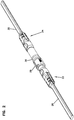
- FIG. 1 illustrates a ruggedized (i.e., hardened) multi-fiber fiber optic connection system 20 in accordance with the principles of the present disclosure.
- the multi-fiber fiber optic connection system 20 includes a first fiber optic connector and fiber optic cable assembly 22 and a second fiber optic connector and fiber optic cable assembly 24 that are configured to interconnect to provide a multi-fiber optical connection.
- the first fiber optic connector and fiber optic cable assembly 22 includes a multi-fiber cable 26 and a hardened connector in the form of a hardened plug 28.
- the hardened plug 28 is mounted on the end of the multi-fiber cable 26.
- the second fiber optic connector and fiber optic cable assembly 24 includes a multi-fiber cable 30 and a hardened connector in the form of a hardened jack 32.
- the hardened jack 32 is mounted at the end of the multi-fiber cable 30.
- the hardened plug 28 and the hardened jack 32 respectively include dust caps 34, 36.
- the dust cap 34 protects an interface end of the hardened plug 28 when the hardened plug 28 is not connected to the hardened jack 32.
- dust cap 36 protects an interface end of the hardened jack 32 when the hardened jack 32 is not connected to the hardened plug 28.
- the hardened plug 28 of the first fiber optic connector and fiber optic cable assembly 22 includes a connector body 38 supporting a multi-fiber ferrule 40 at the interface end of the hardened plug 28.
- An interface piece 42 mounts around the multi-fiber ferrule 40 at a distal end of the connector body 38.
- the multi-fiber ferrule 40 supports ends of a plurality of optical fibers 44 (e.g., 12 optical fibers) corresponding to the multi-fiber cable 26.
- Strength members (not shown) of the multi-fiber cable 26 are secured to a proximal end of the connector body 38.
- the hardened plug 28 also includes a protective housing 46 that mounts over the connector body 38.
- the interface piece 42 When assembled, the interface piece 42 snaps within a proximal end of the protective housing 46 such that the proximal end of the protective housing 46 and the interface piece 42 cooperate to define the interface end of the hardened plug 28. It will be appreciated that end faces of the optical fibers 44 secured within the multi-fiber ferrule 40 are accessible from the interface end of the hardened plug 28.
- a dimensionally recoverable sleeve 48 is secured over an outer jacket of the multi-fiber cable 26 and also over a proximal end of the protective housing 46. In this way, dimensionally recoverable sleeve 48 provides a sealing function that prevents moisture of contaminants from entering the interior of the protective housing 46 through the proximal end of the protective housing 46.
- a boot 300 mounts over the sleeve 48 and is retained on the proximal end of the protective housing 46 by a press-fit or snap-fit connection. The boot 300 is flexible and provides bend radius protection to the cable 26.
- the hardened plug 28 includes a sealing member 50 (e.g., an o-ring seal) that is mounted on the protective housing 46 and circumferentially surrounds a periphery of the protective housing 46.
- the hardened plug 28 further includes a retention nut 52 that mounts over the protective housing 46.
- the retention nut 52 functions to retain the dust cap 34 over the interface end of the hardened plug 28.
- the retention nut 52 includes internal threads 54 that mate with corresponding external threads 56 of the dust cap 34 to secure the dust cap 34 over the interface end of the hardened plug 28.
- the dust cap 34 When the dust cap 34 is secured to the retention nut 52, a proximal end of the retention nut 52 abuts against a shoulder 58 of the housing 46 to stop distal movement of the retention nut 52 relative to the protective housing 46.
- the dust cap 34 engages the sealing member 50 to form a seal that prevents moisture or other contaminants from entering the protective housing 46 through the distal end of the protective housing 46.
- the multi-fiber cable 30 of the second fiber optic connector and fiber optic cable assembly 24 includes a plurality of optical fibers 62 (e.g., 12 optical fibers). In Figure 6 , for clarity, only one of the fibers 62 is shown.
- the multi-fiber cable 30 also includes at least one strength member 64 for reinforcing the fiber optic cable 30. It will be appreciated that the strength member 64 can be configured to provide tensile and/or compressive reinforcement to the multi-fiber cable 30. In certain embodiments, structures such as aramid yarn and/or fiber reinforced epoxy rods can be used. In the depicted embodiment, two strength members 64 are provided.
- the multi-fiber cable 30 further includes a cable jacket 66 for containing the optical fibers 62 and the strength members 64. As shown at Figure 4 , the multi-fiber cable 30 is a flat drop-cable and the cable jacket 66 has an elongated profile when viewed in transverse cross section.
- the hardened jack 32 of the second fiber optic connector and the fiber optic cable assembly 24 includes a connector body 70 having a distal end 72 and a proximal end 74.
- the proximal end 74 includes an anchoring region 76 (see Figure 6 ) for anchoring the strength members 64 of the multi-fiber cable 30.
- the anchoring region 76 includes two parallel channels 78 in which the strength members 64 are received.
- the strength members 64 can be retained in the channels 78 by a material such as adhesive (e.g., epoxy) and can also be mechanically gripped within the channels 78.
- the channels 78 are best shown at Figure 6 .
- the hardened jack 32 includes a multi-fiber ferrule 80 mounted at the distal end 72 of the connector body 70.
- the multi-fiber ferrule 80 supports end portions of the optical fibers 62 of the multi-fiber cable 30. Polished end faces of the optical fibers 62 are positioned at a distal end of the multi-fiber ferrule 80.
- the hardened jack 32 also includes an interface piece 82 that mounts around the multi-fiber ferrule 80.
- a spring 158 is provided for biasing the multi-fiber ferrule 80 in a distal direction relative to the connector body 70.
- the hardened jack 32 includes a protective housing 84 that mounts over the connector body 70.
- the protective housing 84 has a distal end 86 and a proximal end 88.
- the interface piece 82 fits within the distal end 86 of the protective housing 84 and the multi-fiber ferrule 88 is positioned within the interface piece 82.
- the interface piece 82, the multi-fiber ferrule 80 and the distal end 86 of the protective housing 84 cooperate to define the interface end of the hardened jack 32.
- the hardened jack 32 further includes a dimensionally recoverable sleeve 90 positioned over the proximal end 88 of the protective housing 84 and over the jacket 66 of the multi-fiber cable 30 to secure the jacket 66 to the protective housing 84 and to prevent moisture/contaminants from entering the protective housing 84 through the proximal end 88 of the protective housing 84.
- a boot 302 mounts over the sleeve 90 and is retained on the proximal end of the housing 84 by a press-fit or snap-fit connection. The boot 302 is flexible and provides bend radius protection to the cable 30.
- the dust cap 36 is configured to mount over the distal end 86 of the protective housing 84.
- a sealing member 92 is used to form an environmental seal between the dust cap 36 and the protective housing 84 for preventing moisture/contaminants from entering the protective housing 84 through the distal end 86 of the protective housing 84.
- the dust cap 36 is secured to the distal end 86 of the protective housing by a threaded connection.
- the dust cap 36 has internal threads 94 (see Figures 9 and 15 ) that mate with external threads 96 at the distal end 86 of the proximal housing 84 to secure the dust cap 36 on the protective housing 84.
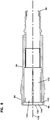
- the dust cap 36 corresponding to the hardened jack 32 includes a distal end 100 and a proximal end 102.
- the dust cap 36 also includes a main body 104 that defines a central dust cap axis 106 (see Figure 15 ) that extends between the distal end proximal ends 100, 102 of the dust cap 36.
- the proximal end 102 of the dust cap 36 is configured to receive the distal end 86 of the protective housing 84.
- the dust cap 36 includes a distal projection 108 at the distal end 100 of the dust cap 36.
- the distal projection 108 projects distally outwardly from the main body 104 and is aligned along the central dust cap axis 106.
- the distal projection 108 has a plurality of wrench flats 110 for allowing a wrench to be used to tighten the threaded connection between the dust cap 36 and the distal end 86 of the protective housing 84 by turning the dust cap 36 relative to the protective housing 84 about the central dust cap axis 106.
- the distal projection 108 defines an opening 112 that forms a pulling eye for allowing a pulling member to be connected to the dust cap 36 and used to pull the fiber optic connector and cable assembly 24 through a conduit (e.g., a conduit in a building, an underground conduit, or other pipe or like structure in which a fiber optic structure can be routed during installation).
- the opening 112 extends through two of the wrench flats 110 of the distal projection 108.
- the opening 112 extends along an opening axis 114 that is perpendicular to the central dust cap axis 106.
- the main body 104 of the dust cap 36 includes inner and outer sleeves 116, 118 that extend around the central dust cap axis 106.
- An annular receptacle 120 is defined between the inner and outer sleeves 116, 118.
- the annular receptacle 120 has an open end 122 opposite from a closed end 124.
- the open end 122 of the annular receptacle 120 faces in a proximal direction.
- the distal end 86 of the protective housing 84 of the hardened jack 32 is received within the annular receptacle 120 through the open end 122 of the annular receptacle 120 (see Fig. 5 ).
- the closed end 124 of the annular receptacle 120 has a stepped configuration.
- the stepped configuration includes first and second radial steps 126, 128 separated by an offset surface 130.
- the offset surface 130 extends distally from the first radial step 126 to the second radial step 128.
- the first radial step 126 extends radially outwardly from the inner sleeve 116 to the offset surface 130.
- the second radial step 128 extends radially outwardly from the offset surface 130 to the outer sleeve 118.
- the offset surface 130 and the second radial step 128 form a deepest portion 132 of the annular receptacle 120.
- the sealing member 92 mounts over the inner sleeve 116 at a location adjacent the first radial step 126.
- the inner sleeve 116 includes inner-sleeve threads 134 positioned within the annular receptacle 120.
- the inner sleeve threads 134 face radially outwardly from the central dust plug axis 106.
- the inner-sleeve threads 134 function to retain the sealing member 92 within the annular receptacle 120 on the inner sleeve 116.
- the outer sleeve 118 defines the internal threads 94 of the dust cap 36.
- the internal threads 94 are positioned within the annular receptacle 120 and face radially inwardly from the outer sleeve 118 toward the central dust plug axis 106.
- the protective housing 84 of the hardened jack 32 defines a central housing axis 136 that coaxially aligns with the dust cap axis 106 when the dust cap 36 is secured to the distal end 86 of the protective housing 84.
- the external threads 96 of the hardened jack 32 are provided at the distal end 86 of the protective housing 84 and are configured to face radially outwardly from the central housing axis 136 of the protective housing 84.
- the internal threads 94 provided on the outer sleeve 118 of the dust cap 36 and the external threads 96 provided at the distal end 86 of the protective housing 84 are configured to mate and form a threaded connection between the dust cap 36 and the protective housing 84.
- the distal end 86 of the protective housing 84 defines an interior bore 140 including a main portion 142 and a sealing portion 144.
- the sealing portion 144 of the interior bore 140 is distally and radially offset from the main portion 142 of the interior bore 140 by a ramp surface 146 (i.e., an incline surface).
- the sealing portion 144 and the main portion 142 of the interior bore 140 are cylindrical and the sealing portion 144 has a larger diameter than the main portion 142.
- the interior bore 140 of the protective housing 84 includes a chamfered portion 150 that expands the diameter of the interior bore 140 as the chamfered portion 150 extends from the sealing portion 144 of the interior bore 140 to a distal-most surface 152 of the protective housing 84.
- the chamfered portion 150 is configured to facilitate inserting the distal end 86 of the protective housing 84 over the sealing member 92 within the dust cap 36.
- the distal-most surface 152 of the protective housing 84 fits within the deepest portion 132 of the annular receptacle 120 of the dust cap 36 (see Fig. 5 ).
- the dust cap 36 includes a stop surface 154 defined by the outer sleeve 118 at a proximal-most extent of the dust cap 36.
- stop surface 154 is oriented in a plane, generally perpendicular to the dust cap axis 106.
- the stop surface 154 abuts against an outer shoulder 156 of the protective housing 84 to provide a positive stop.
- the outer shoulder 156 is aligned along a plane that is perpendicular relative to the central housing axis 136.
- the dust cap 34 is removed from the hardened plug 28 and the dust cap 36 is removed from the hardened jack 32.
- the hardened plug 28 and the hardened jack 32 are then inserted axially together such that the interface ends of the hardened plug 28 and the hardened jack 32 mate with one another.
- the interface pieces 42, 82 mate with one another to provide coarse alignment between the multi-fiber ferrules 40, 80.
- ferrule pins 160 see Fig.
- the multi-fiber ferrule 40 of the hardened plug 28 are received within corresponding ferrule alignment openings 162 (see Figs. 4 and 7 ) defined by the multi-fiber ferrule 80.
- the mating relationship between the alignment pins 160 and the alignment openings 162 provides precise alignment between the multi-fiber ferrules 40, 80 such that the optical fibers 44 supported by the multi-fiber ferrule 40 coaxially align with the corresponding optical fibers 62 supported by the multi-fiber ferrule 80. In this way, the optical fibers 44, 62 of the multi-fiber cables 26, 30 are optically connected together.
- the hardened plug 28 and the hardened jack 32 are securely retained in the fully inserted orientation by threading the retention nut 52 of the first fiber optic connector and fiber optic cable assembly 22 onto the external threads 96 provided at the distal end 86 of the protective housing 84 of the second fiber optic connector and fiber optic cable assembly 24.
- the distal end 86 of the protective housing 84 slides over the sealing member 50 and the sealing member 50 is compressed radially inwardly by the sealing portion 144 of the interior bore and is compressed axially by the ramp surface 146 of the interior bore 140.
- the distal-most surface 152 of the protective housing 84 can function as a stop surface that is oriented generally perpendicular relative to the central housing axis 136 when the hardened plug 28 and the hardened jack 32 are fully inserted together.
- the distal-most surface 152 can abut against a raised shoulder 165 provided on the exterior of the protective housing 46 to provide a positive stop.
- a dimensionally recoverable article is an article the dimensional configuration of which may be made substantially to change when subjected to treatment. Usually these articles recover towards an original shape from which they have previously been deformed, but the term "recoverable” as used herein, also includes an article which adopts a new configuration even if it has not been previously deformed.
- a typical form of a dimensionally recoverable article is a heat recoverable article, the dimensional configuration of which may be changed by subjecting the article to heat treatment.
- such articles comprise a heat-shrinkable sleeve made from a polymeric material exhibiting the property of elastic or plastic memory as described, for example, in U.S. Patents Nos. 2,027,962 (Currie ); 3,086,242 (Cook et al ); and 3,597,372 (Cook ).
- the polymeric material has been crosslinked during the production process so as to enhance the desired dimensional recovery.
- One method of producing a heat recoverable article comprises shaping the polymeric material into the desired heat-stable form, subsequently crosslinking the polymeric material, heating the article to a temperature above the crystalline melting point (or, for amorphous materials the softening point of the polymer), deforming the article, and cooling the article while in the deformed state so that the deformed state of the article is retained.
- application of heat will cause the article to assume its original heat-stable shape.
- the heat recoverable article is a sleeve or a tube that can include a longitudinal seam or can be seamless.
- the heat recoverable sleeve has a dual wall construction including an outer, heat recoverable annular layer, and an inner annular adhesive layer.
- the inner annular adhesive layer includes a hot-melt adhesive layer.
- Such an adhesive layer can be used to bond the sleeve to components such as a cable jacket or a portion of a connector.
- the dimensionally recoverable sleeve 90 can be adhesively bonded to the cable jacket 66 and the proximal end 86 of the protective housing 84.
- sleeve 46 can be adhesively bonded to the jacket of the cable 26 and to the protective housing 46.
- the heat recoverable sleeve is initially expanded from a normal, dimensionally stable diameter to a dimensionally heat unstable diameter that is larger than the normal diameter.
- the heat recoverable sleeve is shape-set to the dimensionally heat unstable diameter. This typically occurs in a factory/manufacturing setting.
- the dimensionally heat unstable diameter is sized to allow the heat recoverable sleeve to be inserted over two components desired to be coupled together. After insertion over the two components, the sleeve is heated thereby causing the heat recoverable sleeve to shrink back toward the normal diameter such that the sleeve radially compresses against the two components to secure the two components together.
- the adhesive layer is preferably heat activated during heating of the sleeve.
Landscapes
- Physics & Mathematics (AREA)
- General Physics & Mathematics (AREA)
- Optics & Photonics (AREA)
- Mechanical Coupling Of Light Guides (AREA)
Claims (9)
- Eine Glasfaserverbinder- und Glasfaserkabelanordnung (24), die Folgendes beinhaltet:ein Glasfaserkabel (30), das eine Vielzahl von Glasfasern (62) umfasst, mindestens ein Festigkeitselement (64) zur Verstärkung des Glasfaserkabels (30) und einen Kabelmantel (66) zur Aufnahme der Glasfasern (62) und des Festigkeitselements (64);einen Verbinderkörper (70), der ein distales Ende (72) und ein proximales Ende (74) aufweist, wobei das proximale Ende (74) einen Verankerungsbereich (76) zur Verankerung des Festigkeitselements (64) des Glasfaserkabels (30) umfasst;eine Multifaserferrule (80), die an dem distalen Ende (70) des Verbinderkörpers (70) montiert ist, wobei die Multifaserferrule (80) Endabschnitte der Glasfasern (62) stützt;ein Schutzgehäuse (84), das über den Verbinderkörper (70) montiert ist, wobei das Schutzgehäuse (84) ein proximales Ende (88) und ein distales Ende (86) aufweist;und eine Staubkappe (36), die sich über das distale Ende (86) des Schutzgehäuses (84) montieren lässt;dadurch gekennzeichnet, dass die Glasfaserverbinder- und Glasfaserkabelanordnung ferner Folgendes beinhaltet:eine dimensionsmäßig rückstellbare Hülse (90), die über dem proximalen Ende (88) des Schutzgehäuses (84) und über dem Mantel (66) des Glasfaserkabels (30) positioniert ist, um den Mantel (66) an dem Schutzgehäuse (84) zu befestigen und um den Eintritt von Verunreinigungen in das Schutzgehäuse (84) durch das proximale Ende (88) des Schutzgehäuses (84) zu verhindern; undein Abdichtelement (92), das eine Abdichtung gegen Umwelteinflüsse zwischen der Staubkappe (36) und dem Schutzgehäuse (84) bildet, um den Eintritt von Verunreinigungen in das Schutzgehäuse (84) zu verhindern.
- Glasfaserverbinder- und Glasfaserkabelanordnung (24) gemäß Anspruch 1, wobei die Staubkappe (36) durch eine Gewindeverbindung an dem distalen Ende (86) des Schutzgehäuses (84) befestigt ist.
- Glasfaserverbinder- und Glasfaserkabelanordnung (24) gemäß Anspruch 2, wobei die Staubkappe (36) ein proximales Ende (102) und ein distales Ende (100) umfasst, wobei die Staubkappe (36) einen Hauptkörper (104) umfasst, der eine zentrale Staubkappenachse (106) definiert, die zwischen dem proximalen und distalen Ende (100, 102) der Staubkappe (36) verläuft, wobei das proximale Ende (102) der Staubkappe (36) das distale Ende (86) des Schutzgehäuses (84) aufnimmt, wobei die Staubkappe (36) einen distalen Vorsprung (108) an dem distalen Ende (100) der Staubkappe (36) umfasst, wobei der distale Vorsprung (108) von dem Hauptkörper (104) aus distal nach außen ragt und entlang der zentralen Staubkappenachse (106) ausgerichtet ist, und wobei der distale Vorsprung (108) eine Vielzahl von Schlüsselflächen (110) aufweist, so dass ein Schlüssel dazu verwendet werden kann, die Gewindeverbindung zwischen der Staubkappe (36) und dem distalen Ende (86) des Schutzgehäuses (84) festzuziehen, indem die Staubkappe (36) relativ zum Schutzgehäuse (84) um die zentrale Staubkappenachse (106) gedreht wird.
- Glasfaserverbinder- und Glasfaserkabelanordnung (24) gemäß Anspruch 3, wobei der distale Vorsprung (108) eine Öffnung (112) definiert, die eine Zugöse bildet, so dass ein Zugelement mit der Staubkappe (36) verbunden und dazu verwendet werden kann, die Glasfaserverbinder- und Glasfaserkabelanordnung (24) durch ein Rohr zu ziehen.
- Glasfaserverbinder- und Glasfaserkabelanordnung (24) gemäß Anspruch 4, wobei die Öffnung (112) durch zwei der Flächen (110) des distalen Vorsprungs (108) verläuft, und wobei die Öffnung (112) entlang einer Öffnungsachse (114) verläuft, die senkrecht zu der zentralen Staubkappenachse (106) liegt.
- Glasfaserverbinder- und Glasfaserkabelanordnung (24) gemäß Anspruch 3, wobei der Hauptkörper (104) der Staubkappe (36) Innen- und Außenhülsen (116, 118) umfasst, die um die zentrale Staubkappenachse (106) herum verlaufen, wobei zwischen den Innen- und Außenhülsen (116, 118) eine ringförmige Aufnahme (120) definiert ist, wobei die ringförmige Aufnahme (120) ein offenes Ende (122) aufweist, das gegenüber einem geschlossenen Ende (124) positioniert ist, wobei das offene Ende (122) in eine proximale Richtung zeigt, wobei das distale Ende (86) des Schutzgehäuses (84) durch das offene Ende (122) der ringförmigen Aufnahme (120) in der ringförmigen Aufnahme (120) aufgenommen wird, wobei das geschlossene Ende (124) der ringförmigen Aufnahme (120) eine abgestufte Konfiguration aufweist, wobei die abgestufte Konfiguration erste und zweite Radialstufen (126, 128) umfasst, die durch eine Versatzoberfläche (130), die distal von der ersten Radialstufe (126) zu der zweiten Radialstufe (128) verläuft, getrennt sind, wobei die erste Radialstufe (126) von der Innenhülse (116) zu der Versatzoberfläche (130) radial nach außen verläuft, wobei die zweite Radialstufe (128) von der Versatzoberfläche (130) zu der Außenhülse (118) radial nach außen verläuft, wobei die Versatzoberfläche (130) und die zweite Radialstufe (128) einen tiefsten Abschnitt (132) der ringförmigen Aufnahme (120) bilden, wobei das Abdichtelement (92) an einer Stelle, die an die erste Radialstufe (126) angrenzt, über die Innenhülse (116) montiert ist, wobei die Innenhülse (116) erste Gewinde (134) umfasst, die in der ringförmigen Aufnahme (120) positioniert sind, und die von der zentralen Staubkappenachse (106) radial nach außen zeigen und das Abdichtelement (92) auf der Innenhülse (116) halten, wobei die Außenhülse (118) zweite Gewinde (94) umfasst, die in der ringförmigen Aufnahme (120) positioniert sind, und die zu der zentralen Staubkappenachse (106) radial nach innen zeigen, wobei das distale Ende des Schutzgehäuses dritte Gewinde (96) umfasst, die von einer zentralen Gehäuseachse (136) des Schutzgehäuses (84) radial nach außen zeigen, wobei die zentrale Gehäuseachse (136) koaxial zu der zentralen Staubkappenachse (106) ausgerichtet ist, wenn die Staubkappe (36) an dem distalen Ende (86) des Schutzgehäuses (84) befestigt ist, und wobei die zweiten und die dritten Gewinde (94, 96) ineinander greifen, um die Gewindeverbindung zwischen der Staubkappe (36) und dem distalen Ende (86) des Schutzgehäuses (84) zu bilden.
- Glasfaserverbinder- und Glasfaserkabelanordnung (24) gemäß Anspruch 6, wobei das distale Ende (86) des Schutzgehäuses (84) eine Innenbohrung (140) definiert, die einen Hauptabschnitt (142) und einen Abdichtabschnitt (144) umfasst, wobei der Abdichtabschnitt (144) der Innenbohrung (140) durch eine Auflaufoberfläche (146) distal und radial von dem Hauptabschnitt (142) der Innenbohrung (140) abgesetzt ist, wobei der Abdichtabschnitt (144) und der Hauptabschnitt (142) der Innenbohrung (140) zylindrisch sind und der Abdichtabschnitt (144) einen größeren Durchmesser als der Hauptabschnitt (142) aufweist, wobei das Abdichtelement (92) zwischen der ersten Radialstufe (126) der Staubkappe (36) und der Auflaufoberfläche (146) des Schutzgehäuses (84) axial komprimiert wird, wenn die Staubkappe (36) an dem distalen Ende (86) des Schutzgehäuses (84) befestigt ist, und wobei das Abdichtelement (92) zwischen dem Abdichtabschnitt (144) der Innenbohrung (140) des Schutzgehäuses (84) und einer zylindrischen Abdichtoberfläche (148) der Innenhülse (116) der Staubkappe (36) radial komprimiert wird, wenn die Staubkappe (36) an dem distalen Ende (86) des Schutzgehäuses (84) befestigt ist.
- Glasfaserverbinder- und Glasfaserkabelanordnung (24) gemäß Anspruch 7, wobei die Innenbohrung (140) des Schutzgehäuses (84) einen angefasten Abschnitt (150) umfasst, der die Innenbohrung (140) erweitert, da der angefaste Abschnitt (150) von dem Abdichtabschnitt (144) der Innenbohrung (140) zu einem distalsten Ende (152) des Schutzgehäuses (82) verläuft.
- Glasfaserverbinder- und Glasfaserkabelanordnung (24) gemäß Anspruch 8, wobei der distalste Abschnitt (152) des Schutzgehäuses (84) in den tiefsten Abschnitt (132) der ringförmigen Aufnahme (120) passt, wenn die Staubkappe (36) an dem Schutzgehäuse (84) befestigt ist.
Applications Claiming Priority (3)
| Application Number | Priority Date | Filing Date | Title |
|---|---|---|---|
| US201261706414P | 2012-09-27 | 2012-09-27 | |
| US14/024,272 US8939654B2 (en) | 2012-09-27 | 2013-09-11 | Ruggedized multi-fiber fiber optic connector with sealed dust cap |
| PCT/US2013/061619 WO2014052414A1 (en) | 2012-09-27 | 2013-09-25 | Ruggedized multi-fiber fiber optic connector with sealed dust cap |
Publications (3)
| Publication Number | Publication Date |
|---|---|
| EP2901189A1 EP2901189A1 (de) | 2015-08-05 |
| EP2901189A4 EP2901189A4 (de) | 2016-04-27 |
| EP2901189B1 true EP2901189B1 (de) | 2018-05-16 |
Family
ID=50338928
Family Applications (1)
| Application Number | Title | Priority Date | Filing Date |
|---|---|---|---|
| EP13840319.1A Active EP2901189B1 (de) | 2012-09-27 | 2013-09-25 | Gehärteter multifaser-glasfaserverbinder mit abgedichteter staubkappe |
Country Status (6)
| Country | Link |
|---|---|
| US (2) | US8939654B2 (de) |
| EP (1) | EP2901189B1 (de) |
| CN (1) | CN104662459B (de) |
| AU (1) | AU2013323714B2 (de) |
| ES (1) | ES2677882T3 (de) |
| WO (1) | WO2014052414A1 (de) |
Families Citing this family (54)
| Publication number | Priority date | Publication date | Assignee | Title |
|---|---|---|---|---|
| US7489849B2 (en) * | 2004-11-03 | 2009-02-10 | Adc Telecommunications, Inc. | Fiber drop terminal |
| CN101907752B (zh) * | 2010-08-02 | 2012-02-01 | 华为技术有限公司 | 防水光纤连接器及室外通信设备 |
| ES2703235T3 (es) | 2011-11-23 | 2019-03-07 | Adc Telecommunications Inc | Conector de fibra óptica multi-fibra |
| CN104364686B (zh) | 2012-02-07 | 2016-11-16 | 泰科电子瑞侃有限公司 | 用于连接器的线缆端接组件和方法 |
| CA2864886A1 (en) | 2012-02-20 | 2013-08-29 | Adc Telecommunications, Inc. | Fiber optic connector, fiber optic connector and cable assembly, and methods for manufacturing |
| US8939654B2 (en) | 2012-09-27 | 2015-01-27 | Adc Telecommunications, Inc. | Ruggedized multi-fiber fiber optic connector with sealed dust cap |
| US9297976B2 (en) * | 2012-11-14 | 2016-03-29 | Clearfield, Inc. | Optical fiber connector |
| WO2014085462A1 (en) | 2012-11-30 | 2014-06-05 | Tyco Electronics Corporation | Fiber optic connector with field installable outer connector housing |
| US10444443B2 (en) | 2013-06-27 | 2019-10-15 | CommScope Connectivity Belgium BVBA | Fiber optic cable anchoring device for use with fiber optic connectors and methods of using the same |
| ES3055341T3 (en) | 2013-08-24 | 2026-02-11 | CommScope Connectivity Belgium BVBA | Ruggedized fiber optic connectors and connection systems |
| CN104849815B (zh) | 2014-02-14 | 2017-01-18 | 泰科电子(上海)有限公司 | 光纤连接器及其组装方法 |
| CN104849816B (zh) | 2014-02-14 | 2017-01-11 | 泰科电子(上海)有限公司 | 光纤连接器及其组装方法 |
| CN105093420A (zh) * | 2014-04-30 | 2015-11-25 | 泰科电子(上海)有限公司 | 插芯组件、光纤连接器及其组装方法、牵引组件 |
| US9720185B2 (en) | 2014-05-23 | 2017-08-01 | Commscope Technologies Llc | Systems and method for processing optical cable assemblies |
| CN105445862B (zh) | 2014-07-09 | 2018-01-19 | 泰科电子(上海)有限公司 | 光纤连接器及其现场组装方法 |
| CN105353472B (zh) * | 2014-08-20 | 2019-12-13 | 中兴通讯股份有限公司 | 一种光纤连接器 |
| US20160054779A1 (en) | 2014-08-22 | 2016-02-25 | Devadatta Bodas | Managing power performance of distributed computing systems |
| WO2016143202A1 (ja) * | 2015-03-06 | 2016-09-15 | 株式会社フジクラ | プラグ側光コネクタ及び光コネクタシステム |
| CN106291826B (zh) * | 2015-05-20 | 2019-05-28 | 华为技术有限公司 | 插头防护帽、光纤连接头组件、光纤插头及网络设备 |
| EP3098634A1 (de) | 2015-05-29 | 2016-11-30 | Corning Optical Communications LLC | Kappenvorrichtungen zum versiegeln von faseroptischen verbindern und zugehörige verfahren |
| EP3098633A1 (de) | 2015-05-29 | 2016-11-30 | Corning Optical Communications LLC | Kappenvorrichtungen zum versiegeln von faseroptischen verbindern und zugehörige verfahren |
| SE538582C2 (sv) * | 2015-06-09 | 2016-09-27 | Lundbring Anders | Male cable connector with a bore for connecting a pull-cord |
| WO2017058629A1 (en) * | 2015-09-28 | 2017-04-06 | Commscope Technologies Llc | End face protection tape for fiber optic connector; and methods |
| EP4403972A3 (de) | 2015-11-30 | 2024-10-16 | CommScope Technologies LLC | Faseroptischer verbinder und dessen zusammenbau |
| EP3391115A4 (de) | 2015-12-16 | 2019-07-17 | Commscope Technologies LLC | Am einsatzort installierter glasfaserverbinder |
| TWM537342U (zh) * | 2016-10-31 | 2017-02-21 | Amphenol Fiber Optic China | 光纖纜線穿設輔助裝置 |
| US10236625B2 (en) * | 2016-11-07 | 2019-03-19 | Otter Products, Llc | Cable retention device |
| KR101878438B1 (ko) * | 2016-11-14 | 2018-07-16 | 주식회사 엑사토 | 엔드-캡 광섬유의 연결구조체 |
| US10718910B2 (en) * | 2017-05-03 | 2020-07-21 | Senko Advanced Components, Inc | Field terminated ruggedized fiber optic connector system |
| CN107193088A (zh) * | 2017-07-28 | 2017-09-22 | 天津华宁电子有限公司 | 一种新型矿用光纤快速连接装置 |
| WO2019104273A1 (en) * | 2017-11-25 | 2019-05-31 | Smith Jack William | Dust and port idetification cap for fiber optic adapters |
| CN108063360B (zh) * | 2017-12-14 | 2023-06-13 | 沈阳兴华航空电器有限责任公司 | 前松后取式电连接器的取送工具 |
| US11221456B2 (en) | 2017-12-19 | 2022-01-11 | Commscope Technologies Llc | Protective tube for micro-duct installation of fiber optic cable |
| TWI727144B (zh) * | 2018-02-14 | 2021-05-11 | 普泰光電股份有限公司 | 具有防水功能的光纖連接器 |
| CN112074995A (zh) | 2018-04-02 | 2020-12-11 | 扇港元器件股份有限公司 | 混合式防渗入连接器和适配器组件 |
| US10948664B2 (en) | 2018-05-08 | 2021-03-16 | Senko Advanced Components, Inc. | Ingress protected optical fiber connector having a reduced diameter with a removable retaining nut |
| CN108732702B (zh) * | 2018-06-01 | 2021-01-15 | 江西扬帆实业有限公司 | 一种光缆接头固定装置 |
| WO2019245778A1 (en) | 2018-06-19 | 2019-12-26 | Commscope Technologies Llc | Assembly for connecting connector with conduit |
| US11092756B2 (en) | 2018-10-10 | 2021-08-17 | Senko Advanced Components, Inc. | Ingress protected connector with an unitary orientation feature |
| US10976502B2 (en) | 2018-10-11 | 2021-04-13 | Seniko Advanced Components, Inc. | Outdoor rated assembly configured to blind mate opposing fiber optic connectors therein with a safety spring assembly |
| WO2020107395A1 (en) * | 2018-11-30 | 2020-06-04 | Corning Optical Fiber Cable (Chengdu) Co., Ltd | Fiber optic cable assemblies and methods of forming the same |
| US11307359B2 (en) | 2019-02-07 | 2022-04-19 | Senko Advanced Components, Inc. | Ingress protected, outdoor rated connector with integrated optical connector plug frame |
| CN110244410B (zh) * | 2019-06-12 | 2021-02-19 | 菲尼克斯亚太电气(南京)有限公司 | 一种光纤连接器 |
| US11906795B2 (en) | 2019-06-19 | 2024-02-20 | Senko Advanced Components, Inc. | Fiber optic connector assembly with crimp tube subassembly and method of use |
| CN110542952B (zh) * | 2019-07-26 | 2021-05-18 | 华为技术有限公司 | 一种光纤连接头以及光纤连接器 |
| CN114207494A (zh) | 2019-08-08 | 2022-03-18 | 扇港元器件有限公司 | 用于户外级连接器组件的推拉机构 |
| CN110729597B (zh) * | 2019-09-29 | 2025-03-04 | 东莞市井岗电子有限公司 | 一种耐老化线材连接器 |
| CN115053162B (zh) | 2019-12-10 | 2025-05-09 | Ppc宽带股份有限公司 | 具有电缆保持特征的机械连接器 |
| TWM602640U (zh) * | 2020-05-22 | 2020-10-11 | 光紅建聖股份有限公司 | 光纜牽引連接裝置 |
| US11934015B2 (en) | 2020-06-09 | 2024-03-19 | Senko Advanced Components, Inc. | Multiport assembly and associated components |
| EP4229458B1 (de) * | 2020-10-16 | 2026-03-18 | Corning Research & Development Corporation | Glasfaserkabelanordnung mit zuggriffanordnung und zugehörige verfahren |
| USD1042350S1 (en) * | 2021-06-25 | 2024-09-17 | Dsm&T Company, Inc. | UV light connector set |
| CN114859476B (zh) * | 2022-05-23 | 2023-09-29 | 国网山东省电力公司淄博供电公司 | 一种新型fc光纤接头组件 |
| CN117055172B (zh) * | 2023-09-20 | 2024-06-25 | 湖南恒凯通信息科技有限公司 | 一种自动对中的光纤连接器 |
Family Cites Families (153)
| Publication number | Priority date | Publication date | Assignee | Title |
|---|---|---|---|---|
| US2027962A (en) | 1933-03-03 | 1936-01-14 | Nat Carbon Co Inc | Production of articles from plastic compositions |
| NL130678C (de) | 1960-07-15 | 1900-01-01 | ||
| NL270833A (de) | 1960-10-31 | |||
| US3777048A (en) | 1971-09-22 | 1973-12-04 | Kaiser Aluminium Chem Corp | Molding process for splicing cable and product formed thereby |
| FR2395518A1 (fr) | 1977-06-22 | 1979-01-19 | Comp Generale Electricite | Connecteur pour fibre optique |
| DE3172553D1 (en) | 1980-11-28 | 1985-11-07 | Toshiba Kk | Method for manufacturing a module for a fiber optic link |
| US4410561A (en) | 1981-07-31 | 1983-10-18 | Bell Telephone Laboratories, Incorporated | Method of forming coated optical fiber |
| JPS58120713U (ja) | 1982-02-06 | 1983-08-17 | 株式会社中西歯科器械製作所 | 光学エア−タ−ビンハンドピ−スにおける光源部回路のスイツチ操作機構 |
| US4389428A (en) | 1982-03-15 | 1983-06-21 | International Telephone And Telegraph Corporation | Method of rejacketing a fusion splice in an ultraviolet light curable resin jacketed optical fiber |
| US4515434A (en) | 1983-03-09 | 1985-05-07 | Allied Corporation | Fiber optic connector |
| GB8327450D0 (en) | 1983-10-13 | 1983-11-16 | Bicc Plc | Optical fibre splicing |
| US4711752A (en) | 1984-06-22 | 1987-12-08 | Itt Corporation | Method and apparatus for molding fiber optic connector ferrule |
| US4662307A (en) | 1985-05-31 | 1987-05-05 | Corning Glass Works | Method and apparatus for recoating optical waveguide fibers |
| US4598974A (en) | 1985-08-15 | 1986-07-08 | International Business Machines Corporation | Optical fiber connector having integral electrodes for use in fusion splicing |
| US4798431A (en) | 1986-12-04 | 1989-01-17 | Itt Corporation | Optic fiber contact |
| NZ222903A (en) | 1986-12-17 | 1990-07-26 | Focas Ltd | Optical fibre connector: heat shrinkable sleeve |
| US4877306A (en) | 1987-09-30 | 1989-10-31 | Corning Glass Works | Coated optical waveguide fibers |
| US5046813A (en) | 1988-09-07 | 1991-09-10 | Fujikura Ltd. | Method and apparatus for aligning a plurality of single-fiber cables, and method of simultaneously fusion-splicing such cables |
| US4964688A (en) | 1988-09-22 | 1990-10-23 | Northern Telecom Limited | Fiber optic connector element and method for its use |
| US4877303A (en) | 1988-09-22 | 1989-10-31 | Northern Telecom Limited | Fiber optic connector element & method for its use |
| US4920366A (en) | 1989-05-31 | 1990-04-24 | Amp Incorporated | Construction of an optical fiber with a connector |
| US5093048A (en) | 1989-08-07 | 1992-03-03 | Grumman Aerospace Corporation | Rejacketing a spliced fiber optic cable |
| US5127820A (en) | 1989-11-07 | 1992-07-07 | Bell Communications Research, Inc. | High-precision adjustable injection molding of single-mode fiber optic connectors |
| US5034170A (en) | 1989-11-07 | 1991-07-23 | Bell Communications Research, Inc. | High-precision adjustable injection molding of single-mode fiber optic connectors |
| US5022735A (en) | 1989-11-07 | 1991-06-11 | The Charles Stark Draper Laboratory, Inc. | Fiber splice coating system |
| US5040867A (en) | 1990-03-21 | 1991-08-20 | Siecor Corporation | Slide fit optical connector having end cap to prevent rotation |
| US5042901A (en) | 1990-07-31 | 1991-08-27 | Siecor Corporation | Preconnectorized optical splice closure |
| CA2071344C (en) | 1991-06-18 | 1997-04-15 | Hiroshi Suganuma | Process for producing an optical fiber coupler |
| US5222171A (en) | 1991-10-21 | 1993-06-22 | Jozef Straus | Fused optical fiber splice element |
| CA2060424C (en) | 1992-01-31 | 1999-12-07 | Ming-Jun Li | Optical coupling element |
| US5263105A (en) | 1992-05-29 | 1993-11-16 | E. I. Du Pont De Nemours And Company | Connector assembly for connecting an optical fiber cable to a socket |
| US5367594A (en) | 1992-09-01 | 1994-11-22 | The Whitaker Corporation | Fiber optic splicer-connector |
| US5317663A (en) | 1993-05-20 | 1994-05-31 | Adc Telecommunications, Inc. | One-piece SC adapter |
| US5375183A (en) | 1993-05-25 | 1994-12-20 | The Whitaker Corporation | Overmolded alignment ferrule |
| JP3087561B2 (ja) | 1993-12-28 | 2000-09-11 | 三菱電機株式会社 | 光半導体モジュールおよびその製造方法 |
| US5740301A (en) | 1994-06-27 | 1998-04-14 | Fiberlign Division Of Preformed Line Products Ltd. | Fusion splicing block with electrodes disposed on planar surface |
| US5465313A (en) | 1994-06-29 | 1995-11-07 | Molex Incorporated | Optical fiber connector and method of fabricating same |
| US5495545A (en) | 1994-10-24 | 1996-02-27 | International Business Machines Corporation | Method for extending bandwidth of large core fiber optic transmission links |
| JPH08234042A (ja) | 1995-03-01 | 1996-09-13 | Furukawa Electric Co Ltd:The | 光ファイバ融着接続装置 |
| AU4937696A (en) | 1995-03-07 | 1996-09-23 | Siemens Aktiengesellschaft | Splicing device for welding optical fibres |
| JPH08262271A (ja) | 1995-03-24 | 1996-10-11 | Hirose Electric Co Ltd | 光ファイバコネクタ用防塵キャップ |
| US5748819A (en) | 1995-04-05 | 1998-05-05 | Siecor Corporation | Field installable optical fiber connector and an associated method of fabrication |
| DE19517750A1 (de) | 1995-05-15 | 1996-11-21 | Siemens Ag | Lichtwellenleiter-Stecker |
| JP3317824B2 (ja) | 1995-08-25 | 2002-08-26 | 株式会社精工技研 | 光減衰ファイバ組立体の製造方法および光減衰ファイバ組立体 |
| JP3620121B2 (ja) | 1995-10-31 | 2005-02-16 | 住友電気工業株式会社 | 光コネクタ及び組立方法 |
| US5832162A (en) | 1995-12-15 | 1998-11-03 | Tii Industries, Inc. | Multiple fiber fusion splice protection sleeve |
| US5815619A (en) | 1996-12-10 | 1998-09-29 | Bloom; Cary | Fiber optic connector hermetically terminated |
| JP3515305B2 (ja) | 1997-01-16 | 2004-04-05 | 株式会社フジクラ | 光コネクタ |
| CA2226052A1 (en) | 1997-02-13 | 1998-08-13 | Diamond Sa | Plug for an optical fiber plug connector and method of its manufacture |
| JP3602339B2 (ja) | 1997-06-16 | 2004-12-15 | 株式会社フジクラ | 光コネクタ |
| US6247850B1 (en) | 1998-11-02 | 2001-06-19 | The Whitaker Corporation | Multiple fiber splice element and connector |
| US6120193A (en) | 1997-12-22 | 2000-09-19 | Siecor Corporation | Splice house subassembly and associated connector |
| US6068410A (en) | 1997-12-22 | 2000-05-30 | Siecor Corporation | Splice housing assembly and associated assembly method for mechanically decoupling a ferrule from a splice body |
| EP0939327A3 (de) | 1998-02-27 | 2002-02-13 | Siemens Aktiengesellschaft | Steckeranschluss für Lichtwellenleiter und Verfahren zu dessen Herstellung |
| US6498888B1 (en) | 1998-04-22 | 2002-12-24 | Institut National D'optique | High-attenuation fiber with cladding mode suppression for all-fiber optical attenuator |
| US6173097B1 (en) | 1998-07-01 | 2001-01-09 | Siecor Operations, Llc | Field installable multifiber connector |
| CN1275210A (zh) | 1998-08-07 | 2000-11-29 | 住友电气工业株式会社 | 光连接器用光纤套管、其成形金属模、光连接器用光纤套管的制造方法及光连接器用光纤套管的检查方法 |
| CA2351326C (en) | 1998-11-26 | 2004-01-27 | Tetsuo Tanaka | Optical fiber connector and ferrule used for it and production method for ferrule |
| DE19933740C2 (de) | 1999-07-19 | 2003-10-30 | Ccs Technology Inc | Lichtwellenleiterstecker und Verfahren zum Anschluß an das Ende eines Lichtwellenleiters |
| US6340249B1 (en) | 1999-09-13 | 2002-01-22 | Alcoa Fujikura Limited | Connector assembly and method of securing fiber optic cable to connector |
| EP1224494A1 (de) | 1999-10-14 | 2002-07-24 | CiDra Corporation | Methode und vorrichtung zur wiederbeschichtung eines faseroptischen spleisses |
| JP2001215358A (ja) | 2000-01-31 | 2001-08-10 | Molex Inc | 光ファイバ用フェルール及びその製造方法 |
| US7090406B2 (en) | 2000-05-26 | 2006-08-15 | Corning Cable Systems Llc | Preconnectorized fiber optic drop cables and assemblies |
| US6648520B2 (en) | 2001-09-28 | 2003-11-18 | Corning Cable Systems Llc | Fiber optic plug |
| DE50113125D1 (de) | 2000-06-05 | 2007-11-22 | Huber+Suhner Ag | Verfahren zum konfektionieren eines optischen steckverbinders, vorrichtung zur durchführung des verfahrens sowie steckverbinder für den einsatz bei einem solchen verfahren |
| AU6255101A (en) | 2000-06-12 | 2001-12-24 | Krone Gmbh | Assembly and method for use in terminating an optical fibre or fibres |
| US6398422B1 (en) * | 2000-07-12 | 2002-06-04 | Molex Incorporated | Dual-function dust cover |
| US6439780B1 (en) | 2000-08-31 | 2002-08-27 | Corning Cable Systems Llc | Field-installable fiber optic ribbon connector and installation tool |
| US6550279B1 (en) | 2000-09-01 | 2003-04-22 | Corning Incorporated | Process for drawing optical fiber from a multiple crucible apparatus with a thermal gradient |
| JP2002082257A (ja) | 2000-09-06 | 2002-03-22 | Sumitomo Electric Ind Ltd | 光コネクタおよび光コネクタ部品 |
| CA2354718A1 (en) | 2000-09-06 | 2002-03-06 | Steve Martin | Molded optical fiber ferrule and method of making the same |
| JP4122699B2 (ja) | 2000-09-29 | 2008-07-23 | 住友電気工業株式会社 | 分散マネージメント光伝送路およびその構成方法 |
| JP4794033B2 (ja) | 2000-10-13 | 2011-10-12 | 住友電気工業株式会社 | 成形用型及び光ファイバ接続部の補強方法並びに光ファイバケーブル |
| US6742936B1 (en) | 2000-11-06 | 2004-06-01 | Corning Cable Systems Llc | Low-loss intermatable ferrules for optical fibers and a method of fabrication thereof |
| US6738552B2 (en) | 2001-01-22 | 2004-05-18 | Gregory Hirsch | Pressed capillary optics |
| US6840687B2 (en) | 2001-02-07 | 2005-01-11 | Fitel Usa Corp. | Systems and methods for low-loss splicing of optical fibers |
| US6532327B1 (en) | 2001-03-13 | 2003-03-11 | 3M Innovative Properties Company | Refractive index grating manufacturing process |
| US6503422B2 (en) | 2001-03-15 | 2003-01-07 | Nuvisions International | Method of fabricating holding devices for fiber optic connector ferrules |
| US6827508B2 (en) | 2001-05-24 | 2004-12-07 | Fiber Optic Network Solutions Corporation | Optical fiber fusion system |
| US6520689B2 (en) | 2001-07-17 | 2003-02-18 | Corning Incorporated | Optical fiber splicing method and device |
| US6588235B2 (en) | 2001-08-30 | 2003-07-08 | Corning Incorporated | Method of centering a fiber core in a multiple-crucible method |
| US6916120B2 (en) | 2002-01-30 | 2005-07-12 | Adc Telecommunications, Inc. | Fiber optic connector and method |
| EP1333301A1 (de) | 2002-01-31 | 2003-08-06 | Sumitomo Electric Industries, Ltd. | Vergussmethode für einen Spleiss optischer Fasern und optische Faser mit vergossenem Spleiss |
| US6918703B2 (en) | 2002-06-12 | 2005-07-19 | Molex Incorporated | System for terminating optical fibers in a fiber optic connector |
| US7220061B2 (en) | 2002-06-24 | 2007-05-22 | Diamond Sa | Connector-plug part for an optical plug-in connection, method for connecting a connector-plug part to the end of an optical waveguide cable and device for carrying out said method |
| US6964578B2 (en) | 2002-07-11 | 2005-11-15 | International Business Machines Corporation | Cable connector retaining assembly, system, and method of assembling same |
| US20040062480A1 (en) | 2002-09-26 | 2004-04-01 | Cronk Bryon J. | Stable recoated fiber bragg grating |
| TW592934B (en) | 2002-12-30 | 2004-06-21 | Ind Tech Res Inst | Method for forming optic fiber connector with thermosetting material |
| US6918704B2 (en) | 2003-01-30 | 2005-07-19 | Panduit Corp. | Tunable fiber optic connector |
| US20050042387A1 (en) | 2003-08-21 | 2005-02-24 | 3M Innovative Properties Company | Filament coating process and apparatus |
| US6856748B1 (en) | 2003-09-30 | 2005-02-15 | Corning Cable Systems Llc | Interconnection enclosure having a connector port and preterminated optical connector |
| US7216512B2 (en) | 2003-10-31 | 2007-05-15 | Corning Cable Systems, Llc | Method of making an optical fiber by laser cleaving |
| US7006739B2 (en) | 2003-12-15 | 2006-02-28 | Corning Cable Systems Llc | Pre-connectorized fiber optic distribution cable |
| US7088893B2 (en) | 2003-11-26 | 2006-08-08 | Corning Cable Systems Llc | Pre-connectorized fiber optic distribution cable having multifiber connector |
| US6979133B2 (en) | 2004-01-26 | 2005-12-27 | John Mezzalingua Associates, Inc. | Epoxy bonded fiber optic connector and method of constructing same |
| US20050238292A1 (en) | 2004-03-24 | 2005-10-27 | Barnes Brandon A | Field installable optical fiber connector having plastic splice holder and metal ferrule holder |
| US7104702B2 (en) | 2004-03-24 | 2006-09-12 | Corning Cable Systems Llc | Field installable optical fiber connector |
| US7147384B2 (en) | 2004-03-26 | 2006-12-12 | 3M Innovative Properties Company | Small form factor optical connector with thermoplastic adhesive |
| US20050213897A1 (en) | 2004-03-29 | 2005-09-29 | Palmer Jeffrey D | Field-installable fusion spliced fiber optic connector kits and methods therefor |
| JP2005352167A (ja) | 2004-06-10 | 2005-12-22 | Fujikura Ltd | 突き合わせ装置およびこの突き合わせ装置を備えた融着接続装置 |
| US20060002662A1 (en) | 2004-06-30 | 2006-01-05 | Tyco Electronics Corporation | Small form factor, field-installable connector |
| US20060045428A1 (en) | 2004-08-24 | 2006-03-02 | Thomas Theuerkorn | Fiber optic receptacle and plug assemblies |
| US20060103039A1 (en) | 2004-11-15 | 2006-05-18 | Shields Jeff L | Heat shrink device and method |
| JP4457873B2 (ja) | 2004-11-30 | 2010-04-28 | 住友電気工業株式会社 | 光ファイバ融着接続装置及び融着接続方法 |
| CN101147088B (zh) | 2005-02-16 | 2011-08-17 | 应用材料股份有限公司 | 光学耦合至ic芯片 |
| US7264402B2 (en) * | 2005-03-10 | 2007-09-04 | Corning Cable Systems Llc | Multi-fiber optic receptacle and plug assembly |
| AU2006236409B2 (en) | 2005-04-19 | 2011-05-19 | Adc Telecommunications, Inc. | Loop back plug and method |
| JP4551819B2 (ja) | 2005-05-31 | 2010-09-29 | 米沢電線株式会社 | 光ファイバ付きフェルールの製造方法 |
| US8094988B2 (en) | 2005-12-15 | 2012-01-10 | Corning Cable Systems Llc | Apparatus and methods for verifying an acceptable splice termination |
| US7329049B2 (en) | 2005-12-27 | 2008-02-12 | Corning Cable Systems Llc | Splice connector for verifying an acceptable splice termination |
| SE530854C2 (sv) | 2005-12-30 | 2008-09-30 | Ericsson Telefon Ab L M | Inriktning av optiska fibrer vid dessas skarvning |
| US7264410B1 (en) | 2006-03-16 | 2007-09-04 | Corning Cable Systems Llc | Dual function splice component for mechanical splice connector |
| JP4240043B2 (ja) | 2006-03-17 | 2009-03-18 | セイコーエプソン株式会社 | ディザマトリックスの生成 |
| US7330624B2 (en) | 2006-04-18 | 2008-02-12 | Corning Cable Systems Llc | Loopback device utilizing bend insensitive optical fiber |
| JP4976226B2 (ja) | 2006-08-07 | 2012-07-18 | 株式会社精工技研 | 光コネクタ部品および光コネクタ |
| WO2008030432A2 (en) | 2006-09-06 | 2008-03-13 | Afl Telecommunications Llc | Spliced-on connector system and method, splicer, and connector holder for producing the same |
| US7412130B2 (en) | 2006-09-18 | 2008-08-12 | X-Rite, Inc. | Fiber optic overmold method and product |
| JP4867590B2 (ja) | 2006-11-07 | 2012-02-01 | 住友電気工業株式会社 | 光ファイバ融着接続機 |
| JP5184865B2 (ja) | 2006-11-13 | 2013-04-17 | 住友電気工業株式会社 | 光コネクタ |
| US20090060427A1 (en) | 2006-12-01 | 2009-03-05 | Wouters Vincent A | Quick terminated fiber optic termini and fiber optic cable, and method for making |
| US7572065B2 (en) | 2007-01-24 | 2009-08-11 | Adc Telecommunications, Inc. | Hardened fiber optic connector |
| US7628549B2 (en) | 2007-01-25 | 2009-12-08 | Fujikura Ltd. | Optical connector |
| US20080193089A1 (en) | 2007-02-13 | 2008-08-14 | Fujikura Ltd. | Optical connector connecting method and structure |
| US7455460B2 (en) | 2007-03-08 | 2008-11-25 | Panduit Corp. | Fiber optic connector with double-clad stub fiber |
| CA2692809A1 (en) | 2007-07-16 | 2009-01-22 | Corning Cable Systems Llc | Fusion-splice fiber optic connectors and related tools |
| JP4886644B2 (ja) | 2007-09-14 | 2012-02-29 | 株式会社精工技研 | 光コネクタキット |
| US7744286B2 (en) | 2007-12-11 | 2010-06-29 | Adc Telecommunications, Inc. | Hardened fiber optic connection system with multiple configurations |
| JP4719755B2 (ja) * | 2008-02-29 | 2011-07-06 | 住友電気工業株式会社 | 光コネクタ |
| US7708476B2 (en) | 2008-07-18 | 2010-05-04 | Corning Cable Systems Llc | Index-matching gel for nano-engineered optical fibers and mechanical splice assemblies and connectors using same |
| AU2009320044B2 (en) | 2008-10-28 | 2014-11-13 | Adc Telecommunications, Inc. | Flat drop cable |
| US20100124394A1 (en) | 2008-11-19 | 2010-05-20 | David Wayne Meek | Process for connecting fibers and connected optical assembly |
| US8109679B2 (en) | 2008-11-25 | 2012-02-07 | Corning Cable Systems Llc | Optical ferrule assemblies and methods of making the same |
| WO2010090211A1 (ja) | 2009-02-05 | 2010-08-12 | 日本航空電子工業株式会社 | 光コネクタ装置 |
| CN102439502B (zh) | 2009-04-06 | 2015-02-18 | Adc电信公司 | 光纤连接器和组装方法 |
| US8646989B2 (en) | 2009-05-19 | 2014-02-11 | Adc Telecommunications, Inc. | Mechanical interface between a fiber optic cable and a fiber optic connector |
| US20100303425A1 (en) | 2009-05-29 | 2010-12-02 | Ziwei Liu | Protected Fiber Optic Assemblies and Methods for Forming the Same |
| CN102230991B (zh) | 2009-10-23 | 2013-01-09 | 鸿富锦精密工业(深圳)有限公司 | 光纤耦合连接器 |
| JP5144623B2 (ja) | 2009-10-28 | 2013-02-13 | Seiオプティフロンティア株式会社 | 光コネクタの組立方法 |
| JP5369053B2 (ja) | 2009-10-28 | 2013-12-18 | Seiオプティフロンティア株式会社 | 光コネクタ |
| WO2011087944A1 (en) | 2010-01-15 | 2011-07-21 | Corning Cable Systems Llc | Fiber optic connector of a fiber optic connection termination system |
| WO2011087941A1 (en) | 2010-01-15 | 2011-07-21 | Corning Cable Systems Llc | Optical fiber handler for a fiber optic connection termination system |
| WO2011087942A1 (en) | 2010-01-15 | 2011-07-21 | Corning Cable Systems Llc | An optical fiber stripper for a fiber optic connection termination system |
| US8262294B2 (en) | 2010-02-04 | 2012-09-11 | Adc Telecommunications, Inc. | Fiber optic dust cap and connector for terminating multi-fiber optical cables |
| US8915659B2 (en) | 2010-05-14 | 2014-12-23 | Adc Telecommunications, Inc. | Splice enclosure arrangement for fiber optic cables |
| KR101038195B1 (ko) | 2010-07-08 | 2011-06-01 | 박찬설 | 광섬유 커넥터와 이의 조립방법 |
| US8885998B2 (en) | 2010-12-09 | 2014-11-11 | Adc Telecommunications, Inc. | Splice enclosure arrangement for fiber optic cables |
| SG193321A1 (en) | 2011-02-25 | 2013-10-30 | Ortronics Inc | Field termination optical fiber connectors and splicers |
| CN102156331B (zh) * | 2011-04-12 | 2013-01-09 | 中天宽带技术有限公司 | 预埋纤式光纤快速连接器 |
| US8494331B2 (en) | 2011-07-06 | 2013-07-23 | Go!Foton Holdings, Inc. | Apparatus and method for mass producing optical fiber splice-on connector subunits |
| ES2703235T3 (es) | 2011-11-23 | 2019-03-07 | Adc Telecommunications Inc | Conector de fibra óptica multi-fibra |
| CA2770903A1 (en) | 2011-11-30 | 2013-05-30 | Her Majesty The Queen In Right Of Canada, As Represented By The Minister Of Industry, Through The Communications Research Centre Canada | Method and apparatus for recoating an optical fiber having a non-uniform diameter |
| CA2864886A1 (en) | 2012-02-20 | 2013-08-29 | Adc Telecommunications, Inc. | Fiber optic connector, fiber optic connector and cable assembly, and methods for manufacturing |
| US8939654B2 (en) | 2012-09-27 | 2015-01-27 | Adc Telecommunications, Inc. | Ruggedized multi-fiber fiber optic connector with sealed dust cap |
-
2013
- 2013-09-11 US US14/024,272 patent/US8939654B2/en active Active
- 2013-09-25 CN CN201380050437.XA patent/CN104662459B/zh active Active
- 2013-09-25 ES ES13840319.1T patent/ES2677882T3/es active Active
- 2013-09-25 EP EP13840319.1A patent/EP2901189B1/de active Active
- 2013-09-25 WO PCT/US2013/061619 patent/WO2014052414A1/en not_active Ceased
- 2013-09-25 AU AU2013323714A patent/AU2013323714B2/en active Active
-
2015
- 2015-01-26 US US14/605,390 patent/US9291780B2/en active Active
Non-Patent Citations (1)
| Title |
|---|
| None * |
Also Published As
| Publication number | Publication date |
|---|---|
| US20140086534A1 (en) | 2014-03-27 |
| EP2901189A1 (de) | 2015-08-05 |
| ES2677882T3 (es) | 2018-08-07 |
| CN104662459B (zh) | 2016-05-18 |
| WO2014052414A1 (en) | 2014-04-03 |
| EP2901189A4 (de) | 2016-04-27 |
| AU2013323714B2 (en) | 2017-05-25 |
| US20150241639A1 (en) | 2015-08-27 |
| CN104662459A (zh) | 2015-05-27 |
| US9291780B2 (en) | 2016-03-22 |
| US8939654B2 (en) | 2015-01-27 |
| AU2013323714A1 (en) | 2015-04-02 |
Similar Documents
| Publication | Publication Date | Title |
|---|---|---|
| EP2901189B1 (de) | Gehärteter multifaser-glasfaserverbinder mit abgedichteter staubkappe | |
| US11971585B2 (en) | Ruggedized fiber optic connectors and connection systems | |
| EP3214471B1 (de) | Verbindungsteil und faseroptischer verbinder | |
| US9625660B2 (en) | Cable termination assembly and method for connectors | |
| EP3234672B1 (de) | Gehärteter glasfaserverbinder mit vorkomprimierter feder | |
| US9217828B2 (en) | Optical fiber protective tubing assembly | |
| CN105511020A (zh) | 光纤连接器及其组装方法 | |
| US20240329312A1 (en) | Splice-on fiber optic connector assembly |
Legal Events
| Date | Code | Title | Description |
|---|---|---|---|
| PUAI | Public reference made under article 153(3) epc to a published international application that has entered the european phase |
Free format text: ORIGINAL CODE: 0009012 |
|
| 17P | Request for examination filed |
Effective date: 20150303 |
|
| AK | Designated contracting states |
Kind code of ref document: A1 Designated state(s): AL AT BE BG CH CY CZ DE DK EE ES FI FR GB GR HR HU IE IS IT LI LT LU LV MC MK MT NL NO PL PT RO RS SE SI SK SM TR |
|
| AX | Request for extension of the european patent |
Extension state: BA ME |
|
| DAX | Request for extension of the european patent (deleted) | ||
| RA4 | Supplementary search report drawn up and despatched (corrected) |
Effective date: 20160329 |
|
| RIC1 | Information provided on ipc code assigned before grant |
Ipc: G02B 6/40 20060101ALI20160321BHEP Ipc: G02B 6/38 20060101AFI20160321BHEP Ipc: G02B 6/36 20060101ALI20160321BHEP |
|
| GRAP | Despatch of communication of intention to grant a patent |
Free format text: ORIGINAL CODE: EPIDOSNIGR1 |
|
| STAA | Information on the status of an ep patent application or granted ep patent |
Free format text: STATUS: GRANT OF PATENT IS INTENDED |
|
| RIC1 | Information provided on ipc code assigned before grant |
Ipc: G02B 6/38 20060101AFI20170921BHEP Ipc: G02B 6/40 20060101ALI20170921BHEP Ipc: G02B 6/44 20060101ALN20170921BHEP |
|
| INTG | Intention to grant announced |
Effective date: 20171013 |
|
| GRAS | Grant fee paid |
Free format text: ORIGINAL CODE: EPIDOSNIGR3 |
|
| RAP1 | Party data changed (applicant data changed or rights of an application transferred) |
Owner name: COMMSCOPE TECHNOLOGIES LLC |
|
| GRAA | (expected) grant |
Free format text: ORIGINAL CODE: 0009210 |
|
| STAA | Information on the status of an ep patent application or granted ep patent |
Free format text: STATUS: THE PATENT HAS BEEN GRANTED |
|
| AK | Designated contracting states |
Kind code of ref document: B1 Designated state(s): AL AT BE BG CH CY CZ DE DK EE ES FI FR GB GR HR HU IE IS IT LI LT LU LV MC MK MT NL NO PL PT RO RS SE SI SK SM TR |
|
| REG | Reference to a national code |
Ref country code: GB Ref legal event code: FG4D |
|
| REG | Reference to a national code |
Ref country code: CH Ref legal event code: EP |
|
| REG | Reference to a national code |
Ref country code: IE Ref legal event code: FG4D |
|
| REG | Reference to a national code |
Ref country code: DE Ref legal event code: R096 Ref document number: 602013037651 Country of ref document: DE |
|
| REG | Reference to a national code |
Ref country code: AT Ref legal event code: REF Ref document number: 1000086 Country of ref document: AT Kind code of ref document: T Effective date: 20180615 |
|
| REG | Reference to a national code |
Ref country code: ES Ref legal event code: FG2A Ref document number: 2677882 Country of ref document: ES Kind code of ref document: T3 Effective date: 20180807 |
|
| REG | Reference to a national code |
Ref country code: NL Ref legal event code: MP Effective date: 20180516 |
|
| REG | Reference to a national code |
Ref country code: FR Ref legal event code: PLFP Year of fee payment: 6 |
|
| REG | Reference to a national code |
Ref country code: LT Ref legal event code: MG4D |
|
| PG25 | Lapsed in a contracting state [announced via postgrant information from national office to epo] |
Ref country code: NO Free format text: LAPSE BECAUSE OF FAILURE TO SUBMIT A TRANSLATION OF THE DESCRIPTION OR TO PAY THE FEE WITHIN THE PRESCRIBED TIME-LIMIT Effective date: 20180816 Ref country code: SE Free format text: LAPSE BECAUSE OF FAILURE TO SUBMIT A TRANSLATION OF THE DESCRIPTION OR TO PAY THE FEE WITHIN THE PRESCRIBED TIME-LIMIT Effective date: 20180516 Ref country code: BG Free format text: LAPSE BECAUSE OF FAILURE TO SUBMIT A TRANSLATION OF THE DESCRIPTION OR TO PAY THE FEE WITHIN THE PRESCRIBED TIME-LIMIT Effective date: 20180816 Ref country code: FI Free format text: LAPSE BECAUSE OF FAILURE TO SUBMIT A TRANSLATION OF THE DESCRIPTION OR TO PAY THE FEE WITHIN THE PRESCRIBED TIME-LIMIT Effective date: 20180516 Ref country code: LT Free format text: LAPSE BECAUSE OF FAILURE TO SUBMIT A TRANSLATION OF THE DESCRIPTION OR TO PAY THE FEE WITHIN THE PRESCRIBED TIME-LIMIT Effective date: 20180516 |
|
| PG25 | Lapsed in a contracting state [announced via postgrant information from national office to epo] |
Ref country code: GR Free format text: LAPSE BECAUSE OF FAILURE TO SUBMIT A TRANSLATION OF THE DESCRIPTION OR TO PAY THE FEE WITHIN THE PRESCRIBED TIME-LIMIT Effective date: 20180817 Ref country code: NL Free format text: LAPSE BECAUSE OF FAILURE TO SUBMIT A TRANSLATION OF THE DESCRIPTION OR TO PAY THE FEE WITHIN THE PRESCRIBED TIME-LIMIT Effective date: 20180516 Ref country code: LV Free format text: LAPSE BECAUSE OF FAILURE TO SUBMIT A TRANSLATION OF THE DESCRIPTION OR TO PAY THE FEE WITHIN THE PRESCRIBED TIME-LIMIT Effective date: 20180516 Ref country code: RS Free format text: LAPSE BECAUSE OF FAILURE TO SUBMIT A TRANSLATION OF THE DESCRIPTION OR TO PAY THE FEE WITHIN THE PRESCRIBED TIME-LIMIT Effective date: 20180516 Ref country code: HR Free format text: LAPSE BECAUSE OF FAILURE TO SUBMIT A TRANSLATION OF THE DESCRIPTION OR TO PAY THE FEE WITHIN THE PRESCRIBED TIME-LIMIT Effective date: 20180516 |
|
| REG | Reference to a national code |
Ref country code: AT Ref legal event code: MK05 Ref document number: 1000086 Country of ref document: AT Kind code of ref document: T Effective date: 20180516 |
|
| PG25 | Lapsed in a contracting state [announced via postgrant information from national office to epo] |
Ref country code: RO Free format text: LAPSE BECAUSE OF FAILURE TO SUBMIT A TRANSLATION OF THE DESCRIPTION OR TO PAY THE FEE WITHIN THE PRESCRIBED TIME-LIMIT Effective date: 20180516 Ref country code: CZ Free format text: LAPSE BECAUSE OF FAILURE TO SUBMIT A TRANSLATION OF THE DESCRIPTION OR TO PAY THE FEE WITHIN THE PRESCRIBED TIME-LIMIT Effective date: 20180516 Ref country code: DK Free format text: LAPSE BECAUSE OF FAILURE TO SUBMIT A TRANSLATION OF THE DESCRIPTION OR TO PAY THE FEE WITHIN THE PRESCRIBED TIME-LIMIT Effective date: 20180516 Ref country code: AT Free format text: LAPSE BECAUSE OF FAILURE TO SUBMIT A TRANSLATION OF THE DESCRIPTION OR TO PAY THE FEE WITHIN THE PRESCRIBED TIME-LIMIT Effective date: 20180516 Ref country code: EE Free format text: LAPSE BECAUSE OF FAILURE TO SUBMIT A TRANSLATION OF THE DESCRIPTION OR TO PAY THE FEE WITHIN THE PRESCRIBED TIME-LIMIT Effective date: 20180516 Ref country code: PL Free format text: LAPSE BECAUSE OF FAILURE TO SUBMIT A TRANSLATION OF THE DESCRIPTION OR TO PAY THE FEE WITHIN THE PRESCRIBED TIME-LIMIT Effective date: 20180516 Ref country code: SK Free format text: LAPSE BECAUSE OF FAILURE TO SUBMIT A TRANSLATION OF THE DESCRIPTION OR TO PAY THE FEE WITHIN THE PRESCRIBED TIME-LIMIT Effective date: 20180516 |
|
| REG | Reference to a national code |
Ref country code: DE Ref legal event code: R097 Ref document number: 602013037651 Country of ref document: DE |
|
| PG25 | Lapsed in a contracting state [announced via postgrant information from national office to epo] |
Ref country code: SM Free format text: LAPSE BECAUSE OF FAILURE TO SUBMIT A TRANSLATION OF THE DESCRIPTION OR TO PAY THE FEE WITHIN THE PRESCRIBED TIME-LIMIT Effective date: 20180516 |
|
| PLBE | No opposition filed within time limit |
Free format text: ORIGINAL CODE: 0009261 |
|
| STAA | Information on the status of an ep patent application or granted ep patent |
Free format text: STATUS: NO OPPOSITION FILED WITHIN TIME LIMIT |
|
| 26N | No opposition filed |
Effective date: 20190219 |
|
| PG25 | Lapsed in a contracting state [announced via postgrant information from national office to epo] |
Ref country code: MC Free format text: LAPSE BECAUSE OF FAILURE TO SUBMIT A TRANSLATION OF THE DESCRIPTION OR TO PAY THE FEE WITHIN THE PRESCRIBED TIME-LIMIT Effective date: 20180516 |
|
| REG | Reference to a national code |
Ref country code: CH Ref legal event code: PL |
|
| PG25 | Lapsed in a contracting state [announced via postgrant information from national office to epo] |
Ref country code: SI Free format text: LAPSE BECAUSE OF FAILURE TO SUBMIT A TRANSLATION OF THE DESCRIPTION OR TO PAY THE FEE WITHIN THE PRESCRIBED TIME-LIMIT Effective date: 20180516 |
|
| REG | Reference to a national code |
Ref country code: BE Ref legal event code: MM Effective date: 20180930 |
|
| REG | Reference to a national code |
Ref country code: IE Ref legal event code: MM4A |
|
| PG25 | Lapsed in a contracting state [announced via postgrant information from national office to epo] |
Ref country code: LU Free format text: LAPSE BECAUSE OF NON-PAYMENT OF DUE FEES Effective date: 20180925 |
|
| PG25 | Lapsed in a contracting state [announced via postgrant information from national office to epo] |
Ref country code: IE Free format text: LAPSE BECAUSE OF NON-PAYMENT OF DUE FEES Effective date: 20180925 |
|
| PG25 | Lapsed in a contracting state [announced via postgrant information from national office to epo] |
Ref country code: LI Free format text: LAPSE BECAUSE OF NON-PAYMENT OF DUE FEES Effective date: 20180930 Ref country code: CH Free format text: LAPSE BECAUSE OF NON-PAYMENT OF DUE FEES Effective date: 20180930 Ref country code: BE Free format text: LAPSE BECAUSE OF NON-PAYMENT OF DUE FEES Effective date: 20180930 |
|
| PG25 | Lapsed in a contracting state [announced via postgrant information from national office to epo] |
Ref country code: AL Free format text: LAPSE BECAUSE OF FAILURE TO SUBMIT A TRANSLATION OF THE DESCRIPTION OR TO PAY THE FEE WITHIN THE PRESCRIBED TIME-LIMIT Effective date: 20180516 |
|
| PG25 | Lapsed in a contracting state [announced via postgrant information from national office to epo] |
Ref country code: MT Free format text: LAPSE BECAUSE OF NON-PAYMENT OF DUE FEES Effective date: 20180925 |
|
| PG25 | Lapsed in a contracting state [announced via postgrant information from national office to epo] |
Ref country code: TR Free format text: LAPSE BECAUSE OF FAILURE TO SUBMIT A TRANSLATION OF THE DESCRIPTION OR TO PAY THE FEE WITHIN THE PRESCRIBED TIME-LIMIT Effective date: 20180516 |
|
| PG25 | Lapsed in a contracting state [announced via postgrant information from national office to epo] |
Ref country code: PT Free format text: LAPSE BECAUSE OF FAILURE TO SUBMIT A TRANSLATION OF THE DESCRIPTION OR TO PAY THE FEE WITHIN THE PRESCRIBED TIME-LIMIT Effective date: 20180516 |
|
| PG25 | Lapsed in a contracting state [announced via postgrant information from national office to epo] |
Ref country code: CY Free format text: LAPSE BECAUSE OF FAILURE TO SUBMIT A TRANSLATION OF THE DESCRIPTION OR TO PAY THE FEE WITHIN THE PRESCRIBED TIME-LIMIT Effective date: 20180516 Ref country code: HU Free format text: LAPSE BECAUSE OF FAILURE TO SUBMIT A TRANSLATION OF THE DESCRIPTION OR TO PAY THE FEE WITHIN THE PRESCRIBED TIME-LIMIT; INVALID AB INITIO Effective date: 20130925 Ref country code: MK Free format text: LAPSE BECAUSE OF NON-PAYMENT OF DUE FEES Effective date: 20180516 |
|
| PG25 | Lapsed in a contracting state [announced via postgrant information from national office to epo] |
Ref country code: IS Free format text: LAPSE BECAUSE OF FAILURE TO SUBMIT A TRANSLATION OF THE DESCRIPTION OR TO PAY THE FEE WITHIN THE PRESCRIBED TIME-LIMIT Effective date: 20180916 |
|
| P01 | Opt-out of the competence of the unified patent court (upc) registered |
Effective date: 20230530 |
|
| PGFP | Annual fee paid to national office [announced via postgrant information from national office to epo] |
Ref country code: IT Payment date: 20230921 Year of fee payment: 11 |
|
| PG25 | Lapsed in a contracting state [announced via postgrant information from national office to epo] |
Ref country code: IT Free format text: LAPSE BECAUSE OF NON-PAYMENT OF DUE FEES Effective date: 20240925 |
|
| PGFP | Annual fee paid to national office [announced via postgrant information from national office to epo] |
Ref country code: DE Payment date: 20250929 Year of fee payment: 13 |
|
| PGFP | Annual fee paid to national office [announced via postgrant information from national office to epo] |
Ref country code: GB Payment date: 20250929 Year of fee payment: 13 |
|
| PGFP | Annual fee paid to national office [announced via postgrant information from national office to epo] |
Ref country code: FR Payment date: 20250925 Year of fee payment: 13 |
|
| PGFP | Annual fee paid to national office [announced via postgrant information from national office to epo] |
Ref country code: ES Payment date: 20251001 Year of fee payment: 13 |