EP2901503B1 - Élément de support et module - Google Patents
Élément de support et module Download PDFInfo
- Publication number
- EP2901503B1 EP2901503B1 EP14711704.8A EP14711704A EP2901503B1 EP 2901503 B1 EP2901503 B1 EP 2901503B1 EP 14711704 A EP14711704 A EP 14711704A EP 2901503 B1 EP2901503 B1 EP 2901503B1
- Authority
- EP
- European Patent Office
- Prior art keywords
- carrier element
- plate
- element according
- heat source
- heat sink
- Prior art date
- Legal status (The legal status is an assumption and is not a legal conclusion. Google has not performed a legal analysis and makes no representation as to the accuracy of the status listed.)
- Not-in-force
Links
- 239000010409 thin film Substances 0.000 claims description 58
- 239000000758 substrate Substances 0.000 claims description 38
- 239000011149 active material Substances 0.000 claims description 28
- 239000000463 material Substances 0.000 claims description 27
- 239000002346 layers by function Substances 0.000 claims description 23
- 230000008859 change Effects 0.000 claims description 3
- 239000007779 soft material Substances 0.000 claims description 2
- 238000005452 bending Methods 0.000 description 16
- 239000004020 conductor Substances 0.000 description 7
- 230000008878 coupling Effects 0.000 description 6
- 238000010168 coupling process Methods 0.000 description 6
- 238000005859 coupling reaction Methods 0.000 description 6
- 229910052751 metal Inorganic materials 0.000 description 6
- 239000002184 metal Substances 0.000 description 6
- 239000004065 semiconductor Substances 0.000 description 6
- 238000005476 soldering Methods 0.000 description 5
- RYGMFSIKBFXOCR-UHFFFAOYSA-N Copper Chemical compound [Cu] RYGMFSIKBFXOCR-UHFFFAOYSA-N 0.000 description 4
- 239000000919 ceramic Substances 0.000 description 4
- 229910052802 copper Inorganic materials 0.000 description 4
- 239000010949 copper Substances 0.000 description 4
- 238000010438 heat treatment Methods 0.000 description 4
- 239000010410 layer Substances 0.000 description 4
- 238000004519 manufacturing process Methods 0.000 description 4
- 230000000930 thermomechanical effect Effects 0.000 description 4
- 238000000151 deposition Methods 0.000 description 3
- 230000008021 deposition Effects 0.000 description 3
- 239000010408 film Substances 0.000 description 3
- 230000003071 parasitic effect Effects 0.000 description 3
- 229910000679 solder Inorganic materials 0.000 description 3
- 230000007704 transition Effects 0.000 description 3
- PXHVJJICTQNCMI-UHFFFAOYSA-N Nickel Chemical compound [Ni] PXHVJJICTQNCMI-UHFFFAOYSA-N 0.000 description 2
- 230000005678 Seebeck effect Effects 0.000 description 2
- 238000004026 adhesive bonding Methods 0.000 description 2
- 150000002739 metals Chemical class 0.000 description 2
- 229920001721 polyimide Polymers 0.000 description 2
- 229910001220 stainless steel Inorganic materials 0.000 description 2
- 239000010935 stainless steel Substances 0.000 description 2
- 229910016312 BiSb Inorganic materials 0.000 description 1
- VYZAMTAEIAYCRO-UHFFFAOYSA-N Chromium Chemical compound [Cr] VYZAMTAEIAYCRO-UHFFFAOYSA-N 0.000 description 1
- 229910005329 FeSi 2 Inorganic materials 0.000 description 1
- 229910002665 PbTe Inorganic materials 0.000 description 1
- 244000089486 Phragmites australis subsp australis Species 0.000 description 1
- 229910000577 Silicon-germanium Inorganic materials 0.000 description 1
- 230000009471 action Effects 0.000 description 1
- 239000000853 adhesive Substances 0.000 description 1
- 230000001070 adhesive effect Effects 0.000 description 1
- 238000006243 chemical reaction Methods 0.000 description 1
- 229910052804 chromium Inorganic materials 0.000 description 1
- 239000011651 chromium Substances 0.000 description 1
- 239000011248 coating agent Substances 0.000 description 1
- 238000000576 coating method Methods 0.000 description 1
- 238000010276 construction Methods 0.000 description 1
- 238000001816 cooling Methods 0.000 description 1
- 229920001971 elastomer Polymers 0.000 description 1
- 239000000806 elastomer Substances 0.000 description 1
- 238000004049 embossing Methods 0.000 description 1
- 239000004744 fabric Substances 0.000 description 1
- 230000004907 flux Effects 0.000 description 1
- 238000001465 metallisation Methods 0.000 description 1
- 238000000034 method Methods 0.000 description 1
- 229910052759 nickel Inorganic materials 0.000 description 1
- 239000004033 plastic Substances 0.000 description 1
- 238000010008 shearing Methods 0.000 description 1
- 238000004544 sputter deposition Methods 0.000 description 1
- OCGWQDWYSQAFTO-UHFFFAOYSA-N tellanylidenelead Chemical compound [Pb]=[Te] OCGWQDWYSQAFTO-UHFFFAOYSA-N 0.000 description 1
- 230000005676 thermoelectric effect Effects 0.000 description 1
- 239000002918 waste heat Substances 0.000 description 1
- 238000003466 welding Methods 0.000 description 1
Images


Classifications
-
- H—ELECTRICITY
- H10—SEMICONDUCTOR DEVICES; ELECTRIC SOLID-STATE DEVICES NOT OTHERWISE PROVIDED FOR
- H10N—ELECTRIC SOLID-STATE DEVICES NOT OTHERWISE PROVIDED FOR
- H10N10/00—Thermoelectric devices comprising a junction of dissimilar materials, i.e. devices exhibiting Seebeck or Peltier effects
- H10N10/10—Thermoelectric devices comprising a junction of dissimilar materials, i.e. devices exhibiting Seebeck or Peltier effects operating with only the Peltier or Seebeck effects
- H10N10/17—Thermoelectric devices comprising a junction of dissimilar materials, i.e. devices exhibiting Seebeck or Peltier effects operating with only the Peltier or Seebeck effects characterised by the structure or configuration of the cell or thermocouple forming the device
Definitions
- the invention relates to a carrier element comprising a connection to a heat source and a connection to a heat sink as well as a thermoelectric thin-film element arranged on the carrier element between the connection to the heat source and the connection to the heat sink. Moreover, the invention relates to a module with a plurality of carrier elements.
- thermoelectric element operated as a generator. It is preferable to use differently doped semiconductor materials for this purpose, which can significantly increase the efficiency compared to thermocouples with two different metals joined together at one end. Common semiconductor materials are Bi 2 Te 3 , PbTe, SiGe, BiSb and FeSi 2 . In order to generate sufficiently high voltages, a plurality of thermocouples is usually electrically connected in series in a thermoelectric element.
- thermoelectric elements consist of several blocks of thermoelectrically active semiconductor material, which are alternately connected at the top and bottom by metal bridges electrically conductive.
- the metal bridges at the same time form the thermal contact surfaces and are insulated by a ceramic plate lying on top.
- thermoelectric thin-film elements are known from the prior art:
- thermoelectric thin film element having a support structure on which a plurality of thermo legs of a first conductive material and a plurality of thermo legs of a second conductive material are applied, wherein the first and second conductive material have a different conductivity and the thermo legs are electrically coupled to each other each two thermo legs form a thermocouple, wherein all thermo legs of the first and second conductive material are arranged side by side on the support structure.
- the cold side of the thermoelectric thin film element is located on one side of the electrically conductive first and second materials and the hot side on the opposite side of the electrically conductive first and second materials.
- thermoelectric thin-film element which has a flexible substrate material, are applied to the thin-film thermocouples.
- the thin-film thermocouples are formed of a combination of materials of two different materials, with the first and second materials set up and so on thermally coupled with each other to form a thermocouple together.
- the two materials are printed on the flexible film or deposited by conventional deposition.
- the coupled strips form a series connection of several thermocouples on a small area.
- thermocouples leads to a high output voltage of the thermocouple.
- the electrical coupling structures on one side of the thermoelectric thin-film element form its hot side
- the coupling structures on the opposite side of the thermoelectric thin-film element form its cold side, wherein the hot side is connected to a coupling element to a heat source and the cold side to a heat sink.
- thermoelectric thin-film element with a hot and a cold side
- the flexible thin-film element is clamped on the hot side between two profiles of a coupling element and on the cold side between two profiles of a heat sink.
- the heat sink is formed in the illustrated embodiment of the clamping profiles on which are arranged away from the clamping profiles extending cooling fins.
- thermoelectrically active materials are brittle and can only be loaded mechanically under pressure. Tensile and shear stress therefore do not lead to plastic deformation, but to breakage of the thermoelectrically active materials.
- thermoelectrically active materials of conventional thermoelectric elements despite different dimensions of the heat source and the If possible, heat sink only to pressure load, the connection of the ceramic plate on the hot side to the heat source sliding.
- the desired in the interest of a high efficiency of the thermoelectric element low thermal resistance between the heat source and the ceramic plate basically requires a very high contact pressure, which, however, prohibits due to the necessary to compensate for different expansions slide bearing. In order to find an optimal compromise in this respect, a uniform frictional connection is required over the entire surface of the slide-mounted ceramic plate, which can be realized only with extremely large, previously not automatable production cost.
- thermoelectric module that extends in a longitudinal direction, with an outer tube and an inner tube disposed within the outer tube and an intermediate space arranged therebetween.
- a first strip-shaped structure and a second strip-shaped structure are provided, wherein the first strip-like structure, starting from a first connection to the inner tube and the second strip-like structure, starting from a second connection to the outer tube in opposite directions in a circumferential direction extend the tubes or their longitudinal direction.
- the strip-shaped structures overlap partially in the circumferential direction or in the longitudinal direction, wherein a pair of semiconductor elements is arranged in the region of the overlap between the first and the second strip-shaped structure.
- the outer tube and the inner tube are arranged to one another such that a thermal expansion of the module is compensated primarily by a relative movement of the outer tube relative to the inner tube.
- the strip-shaped structures are arranged resiliently.
- the present invention seeks to propose a support member having a thermoelectric thin-film element disposed on the support member, which is particularly suitable for the attachment of the thin-film element and the harmful with good thermal connection to a heat source and heat sink tensile and Avoiding shear stresses in the thermoelectric thin-film element, in particular in the thermoelectrically active material.
- thermoelectrically active material which is sensitive to shearing loads is arranged in the remaining areas and is thus not exposed to any shear loads.
- the inventively provided compensation section allows a material connection of the carrier element to the heat source and the heat sink.
- a cohesive connection eliminates the need to build large pressure forces between the heat source or heat sink and the connection of the support member to the heat source or heat sink to achieve a low thermal resistance.
- the cohesive connection allows greater manufacturing tolerances of both the carrier element and the heat source or heat sink. Any manufacturing tolerances can be compensated for example by an adhesive or a solder for the production of the cohesive connection.
- the carrier element has a plate for applying the thermoelectric thin-film element.
- the flat surface is particularly suitable for the attachment of the thermoelectric thin-film element.
- the compensation section can be introduced directly into a relatively thin plate, in particular by embossing. For the preferably cohesive connection of the carrier element to the heat source and the heat sink connecting elements are arranged on the plate.
- each compensation section preferably has a linear-elastic behavior.
- the compensation section may have embossed protrusions and / or depressions to compensate for the stresses due to the different expansions of the heat source and heat sink.
- the compensation section preferably has a knobbed structure with a two-dimensional arrangement of Elevations and depressions. Such a nub structure allows compensation movements of the forces occurring in the compensation section in all spatial directions.
- the elastic compensation section can also be designed in the manner of a pipe compensator as an elastic bellows - also known as bellows.
- Each bellows may be provided with at least one, preferably a plurality of slots which extend transversely to the course of the folds of the bellows. If the folds of the bellows are perpendicular to the main direction of expansion of the heat source, expansions of the heat source with respect to the heat sink perpendicular to the main extension direction are compensated by the slots. Similar to the compensated portion provided with nub structure and the slotted bellows allows compensating movements of the forces occurring in the compensation section in all spatial directions.
- the elastic compensation portion may be made of the same material as the remaining portions of the support member.
- a material for the carrier element and the embossed elastic compensation section metals are used, for example, which can withstand aggressive media and high temperatures well.
- the elastic compensation section can deviate from the other areas of the carrier element also made of soft material, such as technical fabrics or elastomers.
- thermoelectric thin-film element has a substrate and thermoelectrically active material applied to the substrate.
- the thermoelectrically active material has a layer thickness of not more than 150 ⁇ m.
- the substrate is electrically insulating in order to connect mutually separate regions of thermoelectrically active material alternately on the hot and cold side of the thin-film element by metallized regions deposited on the substrate.
- the material of the substrate has a low thermal conductivity.
- the regions of thermoelectrically active material are preferably connected in series.
- the substrate may be flexible, for example formed as a polyimide film.
- the film-formed substrate is preferably strip-shaped with the hot and cold sides on opposite longitudinal sides of the strip.
- the flexible film can also be arranged and fastened to the compensator section completely or partially overlapping on the carrier element. When arranging and fixing the film on the carrier element, however, care must be taken that no thermoelectrically active material is located in the region above the compensator section.
- the substrate may also consist of a rigid material.
- each compensator section is located in a region of the carrier element which does not overlap with the substrate. Otherwise, the elastic and / or flexible behavior of the Kompensatorabitess would be prevented by the rigid material of the substrate.
- thermoelectric thin-film element is integrally bonded to a particular flat surface of the carrier element, for example by gluing or soldering.
- the back side of the substrate to be soldered can be metallized.
- thermoelectric thin film element with a flexible substrate is mounted on the supporting element configured as a plate
- the plate and the substrate in the overlapping sections may have mutually aligned slots which compensate for stresses occurring in the overlapping sections.
- the slits in the plate and the substrate run for this purpose, in particular perpendicular to the main extension direction of the heat source. If the compensation section is designed as a bellows, the slots run perpendicular to its folds.
- the connecting elements are arranged on the plate, which extend at an angle, in particular perpendicular to the plane of the plate. If the connecting elements are designed as tabs, they can be made by bending the plate on opposite longitudinal sides.
- the connecting elements are preferably designed sleeve-shaped. The size of the contact surface between the sleeve and the tube leads to a very good thermal connection. If the sleeve passes through the plate, the tube of the heat sink or heat source can be passed through the sleeve.
- thermoelectric thin-film element In order to achieve a uniform heat coupling or decoupling, a plurality of connecting elements are arranged uniformly along the hot or cold side of the thermoelectric thin-film element. If only one connection element is arranged on the hot side and one connection element on the cold side of the thermoelectric thin-section element, the longitudinal extension of the connection element in the plane of the plate corresponds approximately to the longitudinal extent of the thermoelectric thin-layer element along the hot and cold sides.
- the support element may be provided in partial areas with a functional layer having a higher thermal conductivity than the support element.
- the support element consists for example of stainless steel and the functional layer of copper.
- the functional layer is applied in particular in the region of the connection to the heat source or heat sink and in the overlap region between the support element and the thermoelectric thin-film element.
- the functional layer is interrupted in order to avoid loss heat flows between the cold and hot side of the thermoelectric element, which is applied with its substrate on the functional layer.
- the interruption of the functional layer can be designed as a gap.
- a further decoupling of the heat source from the heat sink can be achieved by dividing the support element, in particular its plate, by at least one slot, wherein a first part of the plate is connected to the heat source on one side of the slot second part of the plate on the opposite side of the slot with the heat sink in thermally conductive connection.
- the first and second part of the plate can be connected to each other by at least one, preferably a plurality of bridges bridging the slot, which are narrow relative to the longitudinal extension of the slot.
- the narrow in relation to the slot length webs flow only low parasitic heat losses from the hot to the cold side. If a functional layer is provided on the carrier element, this is interrupted in the region of the webs.
- the web extension may be formed on the first and / or second part of the plate as a compensation section.
- the material thickness and / or the material properties of the web in the region of the attachment can be changed relative to the other regions of the carrier element.
- the thermoelectrically active material of the thin film element is located exclusively in an area above the slot with respect to the plate surface, the metallized areas of the thin film element alternately thermally conductive on its hot side with the first part on its cold side with the second part of the plate or functional layer are connected.
- the web projections acting as compensation sections define on both sides of the thermoelectrically active material in each case a bending line for receiving the different expansions of the heat source and heat sink.
- the bend lines extend along the transition regions of the thermoelectrically active material to the metallized contact regions on the flexible substrate.
- the substrate can follow a rotational movement about the bending line of the carrier element, without stressing thermoelectrically active material by shear forces.
- the slot has a slot width of 4 mm and the thermoelectrically active material has an extension of 2 mm in the direction of the slot width, a transitional area of 1 mm in each case arises on both sides with a central arrangement of the thermoelectrically active material in the slot. In this transition area, the bending line runs.
- the heat sink and / or heat source comprises at least one tube for a heat transfer medium, to which the carrier element is connected. This allows, for example, the waste heat from a Use heating circuit in one or more thermoelectric thin-film elements.
- thermoelectric thin-film elements As the tubes of the heat source or heat sink and the sleeve-shaped connecting elements receiving them extend perpendicularly to the plate of the carrier element, the heat flow in the thermoelectric thin-film elements runs transversely to the flow direction of the heat carrier in each tube. As a result, a temperature drop along the thermoelectric thin-film element is avoided, resulting in a significant increase in performance.
- an arrangement of the carrier elements transversely to the longitudinal extent of the heat source and heat sink allows the proper functioning of the compensation section in the web approach.
- thermoelectric thin-film elements can be combined to form a module.
- the thin-film elements mounted on the plurality of carrier elements can be partially electrically connected in series or in parallel.
- the plate of the support member is annular and divided by a slot in two concentric circular rings.
- a shaped support member allows connection to an elongated, in particular tubular heat source and heat sink, both of which extend perpendicular to the annular plate.
- the connecting elements for connection to the heat source and heat sink also extend perpendicular to the plane of the plate.
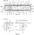
- FIG. 1a shows a sectional side view of a carrier element according to the invention (10) on which a thermoelectric thin-film element (20) is arranged.
- the carrier element (10) is designed as a sheet metal part, for example Made of stainless steel sheet and consists of an elongated rectangular plate (11) which is provided at its longitudinal edges with connecting elements (13 a, b), which in the embodiment according to FIG. 1 are designed as tabs. The tabs may be bent portions of the sheet metal part.
- the lower connecting element (13a) serves for connection to a heat sink (30) and the upper connecting element (13b) for connection to a heat source (40).
- the heat sink (30) and the heat source (40) each comprise a tube (31, 41) with an elongate, rectangular cross-section for a heat transfer medium, which flows through the tubes (31, 41) transversely to the plane of the plate.
- the tube cross-section extends over the entire length of the strip-shaped thermoelectric thin-film element (20) applied to the carrier element (10).
- the designed as a flap upper connecting element (13b) is cohesively with the underside of the tube (41) and designed as a flap lower connecting element (13a) is firmly bonded to the top of the tube (31).
- the material connection is effected in particular by a solder.
- the plate (11) of the carrier element (10) is divided centrally into a first and a second part (11a, 11b) by a slot (14) running parallel to its longitudinal edges (12), the first part (11a) of the plate (11) 11) with the heat source (40) and the second parts (11b) of the plate on the opposite longitudinal side of the slot (14) with the heat sink (30) is in thermally conductive connection.
- the first part (11a) and the second part (11b) of the plate (11) are interconnected by a web (15) bridging the slot (14).
- the web projections (15a) on the first part (11a) and the web extensions (15b) on the second part (11b) of the plate (11) define two bending lines as compensation sections (16) extending parallel to the longitudinal edges (12) of the plate (11).
- the compensation sections (16) of the carrier element (10) thus formed compensate for different thermo-mechanical expansions of the heat source (40) and the heat sink (30).
- thermoelectric thin-film element (20) detects in the embodiment FIG. 1a, b a flexible, strip-shaped substrate (21), for example in the form of a polyimide film, on which the thermoelectrically active material (22) is applied in separate regions (23).
- the application can take place, for example, by way of sputtering deposition or other methods known per se for the deposition of layers.
- the separated regions (23) of thermoelectrically active material (22) are connected in alternation on a hot side (24) and a cold side (25) of the thermoelectric thin-film element (20) through metallized regions (26) to each other in a series connection.
- the hot and cold sides (24, 25) of the thermoelectric thin-film element run parallel to the longitudinal edges (12) of the plate (11) of the carrier element (10).
- the hot side (24) is thermally conductive with the connecting element (13b) for connection to the heat source (40) and the cold side (25) thermally conductively connected to the connecting element (13a) to the heat sink (30).
- the carrier element (10) is provided in partial regions with a functional layer (17) (hatched representation), which has a higher thermal conductivity than the carrier element (10).
- the functional layer consists in the embodiment of copper.
- the plate (11) of the carrier element (10) is provided in the region of the first and second parts (11a, 11b) of the plate (11) with the functional layer (17).
- the functional layer (17) is also applied to the surfaces of the connecting elements (13a, 13b) which come into contact with the tubes (31, 41) in order to achieve a good thermal connection to the heat sink (30) or heat source (14) ,
- the substrate In order to fasten the flexible substrate (21) of the thermoelectric thin-film element (20) on the functional layer (17) of the carrier element, the substrate is provided on its rear side facing the functional layer (17) with a coating, in particular metallization, which performs a soldering of the Thermoelectric thin-film element (20) on the provided with the functional layer (17) support element (10).
- thermoelectrically active material (22) do not extend over the entire slot width (14a) between the hot and cold sides (24, 25).
- the slot width is 4 mm, while the areas (23) with the thermoelectrically active material (22) extend only over a length of 2 mm.
- the thermoelectrically active material (22) arranged centrally above the slot (14) ensures that no thermoelectrically active material is located in the region of the bending lines defined by the web extensions (15a, 15b). Along these bending lines is only the flexible substrate (21), which is not affected by the bend.
- the carrier element (10) according to FIG. 1 works as follows:
- the tube (41) of the heat source (40) Upon heating the tube (41) of the heat source (40), the tube (41) expands relative to the tube (31) of the heat sink (30) primarily transverse to the surface of the plate (11), as in the right half of the picture of the FIG. 1 a is shown. Stresses due to the thermo-mechanical expansion between the heat source (40) and the heat sink (30) are introduced into the webs (15) of the carrier element (10) and cause in the web extensions (15a, 15b) a bending movement to the by the web projections (15a , 15b) defined bending lines, which run parallel to the longitudinal edges (12). Due to the bending around the bending lines lying in the plane of the plate, the expansions transversely to the plane of the plate can be completely compensated in the compensation sections (16).
- FIG. 2 shows an embodiment of a support element (10) on which a thermoelectric thin-film element (20) with a rigid substrate (27) is arranged.
- the carrier element (10) consisting of copper sheet is particularly suitable for high-temperature applications. It detects in accordance with the embodiment FIG. 1 a plate (11) divided into a first part (11a) and a second part (11b) by a slot (14), but with a significantly larger slot width (14a), on which the rigid substrate (27) of the thermoelectric thin-film element (11) 20) is attached heat-conducting, for example by soldering.
- the connecting elements (13a, 13b) for connection to the heat sink (30) or heat source (40) are also designed as tabs.
- the upper connecting element (13b) is connected via a compensation section (16) to the upper longitudinal edge (12) of the plate (11).
- the lower connecting element (13b) is connected via a compensation section (16) to the lower longitudinal edge (12) of the plate (11).
- the two compensation sections (16) do not overlap with the rigid substrate (27), but extend from the Longitudinal edges (12) of the plate (11) in the direction of the heat sink (30) and the heat source (40).
- the connecting elements (13a, 13b) designed as lugs are connected in a materially cohesive manner to the heat source or heat sink (30, 40), as in the exemplary embodiment FIG. 1 ,
- the compensation sections (16) are designed as an elastic bellows (18) which extends over the entire length of the carrier element (10).
- the compensation section (16) may comprise a two-dimensional sequence of protrusions (16a) and depressions (16b), as shown in FIG FIG. 3a is recognizable.
- a nub structure formed in this way allows compensation movements in all spatial directions.
- the carrier element (10) according to FIG. 2 works as follows:
- thermoelectric thin-film element (20) arranged on the plate (11) is not loaded.
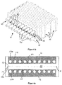
- the carrier element (10) according to FIG. 4a agrees in construction with the support element (10) FIG. 1a, b largely coincide, so that to avoid repetition on the local statements reference is made in full. Differences arise with regard to the structure of the heat sink and the heat source (30, 40) and the connection of the support element to the heat source and heat sink (30, 40).
- the heat sink (30) and the heat source (40) each comprise a tube bundle (32, 42).
- the tubes of a tube bundle (32, 42) extend parallel and at a distance from one another, wherein each tube of the tube bundle (32, 42) extends perpendicular to the plate plane of the carrier element (10).
- thermoelectric thin-film element (20) On the plate (11) of the carrier element (10) are on the hot and cold side (24, 25) of the thermoelectric thin-film element (20) corresponding to the number of tubes of the tube bundle (32, 42) formed as sleeves connecting elements (13a, 13b) arranged.
- the outer sheath of each tube is preferably cohesively connected, for example by means of a solder connection with one of the sleeves.
- the large-area connection of the carrier element (10) via the sleeves to the tubes of the heat sink or heat source (30, 40) increases the heat flux density and increases the efficiency of standing with the support member (10) in thermally conductive connection thermoelectric thin-film element (20).
- the carrier element (10) according to FIG. 4 a works as follows:
- the heat source (40) When heating the tubes of the tube bundle (42), the heat source (40) expands relative to the tubes of the tube bundle (32) of the heat sink (30) primarily transversely to the surface of the plate (11). Stresses due to the different expansions between the heat source (40) and the heat sink (30) are introduced into the webs (15) of the carrier element (10) and cause in the web extensions (15a, 15b) a bending movement to the by the web projections (15a , 15b) defined bending lines, which extend parallel to the longitudinal edges (12) of the plate (11). Due to the bending around the bending lines lying in the plane of the plate, the expansions transversely to the plane of the plate can be completely compensated in the compensation sections (16).
- FIG. 4b shows a module (50), the more identical support elements (10) after FIG. 4a comprises, wherein all support elements (10) in the same way, in the manner of a stack, to the tube bundles (32, 42) of the heat sink (30) or heat source (40) are connected.
- Each tube of the two tube bundles (32, 42) runs perpendicular to the plate plane of the carrier elements (20).
- the heat sink (30) or heat source (40) each comprises only a single circular cross-section tube (31, 41).
- the contour of the carrier element (10) is different from the previous embodiments, not rectangular, but oval.
- the connecting elements (13a, 13b) are according to the embodiment according to FIG. 4a designed as sleeves.
- the oval plate is also divided by a horizontally extending slot (14).
- the first part (11a) and the second part (11b) of the plate are connected to each other by the two outer, the slot bridging webs (15). Consistent with the other embodiments, the web extensions (15a, 15b) on the first and second parts (11a, 11b) of the plate (11) form the elastic compensation section (16) of the carrier element.
- the highly thermally conductive functional layer (17) is not provided in the region of the webs (15) and in the region of the slot (14).
- the functional layer is applied to the inner surface of the sleeves in order to improve the thermal connection to the surface of the heat source or heat sink (30, 40).
- a plurality of matching identical support elements (10) in a kind of stack on the tube of the heat sink (30) or the tube of the heat source (40) can be arranged one behind the other.
- the embodiment of the carrier element (10) according to FIG. 5b corresponds to the embodiment of the carrier element according to FIG. 4a with the difference that the heat source and the heat sink (30, 40) is not formed as a tube bundle (32, 42), but as a rectangular in cross-section tube (31, 41) extending over the full width of the in FIG. 5b not shown, thermoelectric thin-film element (20) with flexible substrate (21).
- the operation of the compensation section (16) corresponds to that according to the embodiments according to FIGS. 1 . 4 and 5 , so that reference is made to avoid repetition on the statements there.
- the carrier element (10) according to FIG. 5c is for the arrangement of two strip-shaped, in FIG. 5c not shown flexible thermoelectric thin-film elements (20) suitable. In the middle extends over the length of the carrier element (10) designed as an elongated rectangular sleeve connecting element (13a) for connection to the heat source (40) by a central, rectangular in cross section tube (41).
- the plate (11) of the carrier element is divided by a slot (14), wherein in each case a first part (11a) of the plate (11) on a longitudinal side of the slot (14 ) with the heat source (40) and in each case a second part (11b) of the plate (11) on the opposite side of each slot (14) with one of the two tubes (31) of the heat sink (30) in heat-conducting connection.
- the web projections (15a, 15b) represent the compensation sections (16) of the support element between the connection to the heat source (40) and the connection to the heat sinks (30).
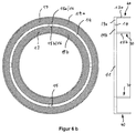
- FIGS. 6a . 6b show an embodiment of a support element (10) with an annular plate (11) on the ring a flexible thermoelectric thin-film element (20) is arranged.
- the annular plate (11) is divided by a circular slot (14) into two concentric circular rings (19a, 19b).
- the circular rings (19a, 19b) are at four offset by 90 degrees to each other arranged locations the slot (14) bridging by webs (15) connected to each other.
- a circumferential over the entire circumference connecting element (13a) for connection to a heat source (40) is arranged.
- a connecting element (13b) extending over the entire circumference is arranged for connection to a heat sink (30).
- the connecting elements (13a, 13b) formed as tabs extend at right angles to the plate surface.
- the functional layer (17) of highly thermally conductive material is mounted on the outwardly facing annular surface of the annuli (19a, 19b) which comes into contact with the thermoelectric thin film element. In order to avoid parasitic heat flows from the hot to the cold side (24, 25), the surfaces of the webs (15) are not provided with the functional layer (17).
- the functional layer (17) is located on the surface regions of the connecting elements (13a, 13b) which serve to connect to the heat source (40) and the heat sink (30).
- the annular support member (10) allows a coaxial arrangement of heat source (40) and heat sink (30), as described below with reference to FIG. 8 is explained. Different extensions between the heat source (40) and the heat sink (30) parallel to the extension of the connecting elements (13a, 13b) are compensated in the web projections (15a, 15b) of the webs (15) by bending.
- the arrangement of the thermoelectrically active materials (22) of the flexible thermoelectric thin film element (20) with respect to the slot (14) corresponds to the arrangement according to FIGS. 1 . 4 and 5 ,
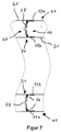
- the embodiment according to FIG. 7 differs from the annular support member (10) FIG. 6a . b in that the thermoelectric thin-layer element (20) applied to the carrier element (10) has a rigid substrate (27).
- the arrangement of the compensation sections (16) and the connecting elements (13a, 13b) corresponds to the structure according to FIG. 2 , so that reference is made to the statements there in full.
- the connecting portions (13a, 13b) of the carrier element (10) are connected to coaxially arranged tubes of a heat sink (30) and heat source (40).
- the carrier element (10) consists in particular of a copper sheet.
- the connecting elements (13 a, b) are connected by soldering, gluing or welding cohesively to the tubes (31, 41) of heat sink and heat source (30, 40).
- the carrier element after FIG. 7 is particularly suitable for applications in the temperature range above 250 degrees Celsius, since the rigid substrate (27) may also consist of high temperature resistant material.
- FIG. 8 shows a module (50) comprising a plurality of identical support elements (10) in one embodiment FIG. 6 or 7 ,
- the support elements (10) are successively spaced evenly on a pipe (31) of the heat sink (30) arranged and connected by means of the connecting elements (13b) cohesively with the lateral surface of the tube (31).
- the connecting elements (13a) arranged on the outer circumference of the annular carrier elements are arranged on an inner jacket tube (33) of the heat source (40).
- the heat source (40) further comprises an outer jacket tube (34) which surrounds the inner jacket tube (33) to form an annular space (35). End plates close end plates (36a, 36b) the annulus (35).
- connecting pieces (52a, 52b) are arranged on the outer jacket tube (34) of the heat source (40).
- a heat transfer medium is conducted via the connecting piece (52a) into the annular space (35) and leaves the annular space via the connecting piece (52b).
Landscapes
- Cooling Or The Like Of Semiconductors Or Solid State Devices (AREA)
- Thermotherapy And Cooling Therapy Devices (AREA)
- Measuring Temperature Or Quantity Of Heat (AREA)
Claims (26)
- Élément porteur (10) comprenant une liaison sur une source de chaleur (40) et une liaison sur un dissipateur thermique (30), ainsi qu'un élément thermoélectrique (20) en couche mince placé sur l'élément porteur (10), entre la liaison sur la source de chaleur (40) et la liaison sur le dissipateur de chaleur (30), avec un côté chaud et un côté froid (24, 25), le côté chaud (24) étant relié de manière conductrice de chaleur avec la liaison sur la source de chaleur (40) et le côté froid (25) étant relié de manière conductrice de chaleur avec la liaison sur le dissipateur thermique (30), caractérisé en ce que- l'élément porteur (10) comporte une plaque (11) pour l'application de l'élément thermoélectrique (20) en couche mince et des éléments de liaison (13a, b) placés sur la plaque (10), pour la liaison de l'élément porteur (10) sur la source de chaleur (40) et sur le dissipateur thermique (30), ainsi- qu'en ce qu'entre la liaison sur la source de chaleur (40) et la liaison sur le dissipateur thermique (30), au moins une section compensatrice (16) élastique et/ou souple de l'élément porteur (10) est aménagée de sorte à compenser des dilatations différentes de la source de chaleur et du dissipateur thermique par une variation de forme de la section compensatrice (16).
- Élément porteur selon la revendication 1, caractérisé en ce que la section compensatrice (16) fait preuve d'un comportement élastique linéaire.
- Élément porteur selon la revendication 1 ou la revendication 2, caractérisé en ce que la section compensatrice (16a) comporte des élévations (16a) et/ou des creux (16b).
- Élément porteur selon la revendication 1 ou la revendication 2, caractérisé en ce que la section compensatrice (16) comporte une structure en noppes.
- Élément porteur selon la revendication 1 ou la revendication 2, caractérisé en ce que la section compensatrice (16) est conçue en tant que soufflet (18) élastique.
- Élément porteur selon la revendication 1 ou la revendication 2, caractérisé en ce que la section compensatrice (16) est constituée d'une matière souple.
- Élément porteur selon l'une quelconque des revendications 1 à 6, caractérisé en ce que l'élément thermoélectrique (20) en couche mince comporte un substrat (21, 27) et une matière thermoélectrique active (22) appliquée sur le substrat (21, 27).
- Élément porteur selon la revendication 7, caractérisé en ce que des régions (23) séparées l'une de l'autre dans la matière thermoélectrique active (22) sont reliées les unes aux autres de manière conductrice d'électricité par des régions métallisées (26), en alternance sur le côté chaud et le côté froid (24, 25) de l'élément en couche mince (20).
- Élément porteur selon la revendication 7 ou la revendication 8, caractérisé en ce que le substrat (21) est constitué d'une matière flexible.
- Élément porteur selon la revendication 7 ou la revendication 8, caractérisé en ce que le substrat (27) est constitué d'une matière résistant à la flexion.
- Élément porteur selon l'une quelconque des revendications 1 à 10, caractérisé en ce que le substrat (21, 27) est placé sur la surface de l'élément porteur (10) de telle sorte qu'aucune matière thermoélectrique active (22) ne se trouve dans une région au-dessus d'une surface d'une section compensatrice (16) de l'élément porteur (10).
- Élément porteur selon l'une quelconque des revendications 1 à 11, caractérisé en ce que la liaison sur la source de chaleur (40) et la liaison sur le dissipateur thermique (30) sont des liaisons par matière.
- Élément porteur selon l'une quelconque des revendications 1 à 12, caractérisé en ce que les éléments de liaison (13a, b) sont conçus en tant que douilles et s'étendent à la perpendiculaire du plan de la plaque.
- Élément porteur selon l'une quelconque des revendications 1 à 12, caractérisé en ce que les éléments de liaison (13a, b) sont conçus en tant que pattes, qui s'étendent notamment à la perpendiculaire du niveau de la plaque.
- Élément porteur selon l'une quelconque des revendications 1 à 14, caractérisé en ce que dans des régions partielles, il est muni d'une couche fonctionnelle (17) qui fait preuve d'une conductivité plus importante que le matériau de l'élément porteur (10).
- Élément porteur selon l'une quelconque des revendications 1 à 15, caractérisé en ce que la plaque (11) est divisée par au moins une encoche (14), sur un côté longitudinal de l'encoche (14), une première partie de (11a) de la plaque étant en liaison conductrice d'électricité avec la source de chaleur (40) et sur le côté longitudinal opposé de l'encoche (14), une deuxième partie (11b) de la plaque (11) étant en liaison conductrice d'électricité avec le dissipateur thermique (30).
- Élément porteur selon la revendication 16, caractérisé en ce que la première et la deuxième parties (11a, b) de la plaque (11) sont reliées l'une à l'autre par au moins un listel (15) chevauchant l'encoche (14).
- Élément porteur selon la revendication 17, caractérisé en ce que chaque base de listel (15a, 15b) est conçue sur la première et/ou la deuxième partie (11a, b) de la plaque (11) en tant que section compensatrice (16) élastique.
- Élément porteur selon la revendication 18, caractérisé en ce que la matière thermoélectrique active (22) de l'élément thermoélectrique (20) en couche mince se trouve exclusivement dans une région au-dessus de l'encoche (14), par rapport à la surface de la plaque.
- Élément porteur selon l'une quelconque des revendications 15 à 19, caractérisé en ce que la plaque (11) est de forme annulaire et est divisée par l'encoche (14) en deux anneaux de cercle (19a, b) concentriques.
- Élément porteur selon l'une quelconque des revendications 1 à 19, caractérisé en ce que la plaque (11) est rectangulaire.
- Élément porteur selon l'une quelconque des revendications 1 à 21, caractérisé en ce que le dissipateur thermique (30) et/ou la source de chaleur (40) comprend au moins un tube (31, 41) pour un caloporteur, auquel est relié l'élément porteur (10).
- Élément porteur selon la revendication 22, caractérisé en ce que chaque tube (31, 41) s'étend à la perpendiculaire du plan de la plaque de l'élément porteur (10).
- Module (50) comprenant un ou plusieurs éléments porteurs (10) de conception identique selon l'une quelconque ou plusieurs des revendications 1 à 23 et une source de chaleur (40) commune et/ou un dissipateur thermique (30) commun, sur laquelle/lequel sont reliés tous les éléments porteurs (10).
- Module (50) selon la revendication 24, caractérisé en ce que le dissipateur thermique (30) et/ou la source de chaleur (40) comprend au moins un tube (31, 41) pour la circulation d'un caloporteur, auquel sont reliés tous les éléments porteurs.
- Module selon la revendication 25, caractérisé en ce que chaque tube (31, 41) s'écoule à la transversale de la surface de chaque élément porteur (10).
Applications Claiming Priority (2)
| Application Number | Priority Date | Filing Date | Title |
|---|---|---|---|
| DE102013102240 | 2013-03-06 | ||
| PCT/EP2014/054286 WO2014135600A1 (fr) | 2013-03-06 | 2014-03-05 | Elément de support et module |
Publications (2)
| Publication Number | Publication Date |
|---|---|
| EP2901503A1 EP2901503A1 (fr) | 2015-08-05 |
| EP2901503B1 true EP2901503B1 (fr) | 2016-04-27 |
Family
ID=50343746
Family Applications (1)
| Application Number | Title | Priority Date | Filing Date |
|---|---|---|---|
| EP14711704.8A Not-in-force EP2901503B1 (fr) | 2013-03-06 | 2014-03-05 | Élément de support et module |
Country Status (4)
| Country | Link |
|---|---|
| US (1) | US20150349233A1 (fr) |
| EP (1) | EP2901503B1 (fr) |
| CN (1) | CN105378955B (fr) |
| WO (1) | WO2014135600A1 (fr) |
Families Citing this family (7)
| Publication number | Priority date | Publication date | Assignee | Title |
|---|---|---|---|---|
| WO2016062928A1 (fr) * | 2014-10-21 | 2016-04-28 | Hutchinson | Dispositif thermoelectrique et d'isolation thermique pour nacelle de moteur d'aeronef, nacelle et procede de fabrication du dispositif |
| DE102015213294A1 (de) | 2015-07-15 | 2017-01-19 | Mahle International Gmbh | Thermoelektrischer Wärmetauscher |
| CN118935853A (zh) | 2018-04-19 | 2024-11-12 | 恩伯技术公司 | 具有主动温度控制的便携式冷却器 |
| GB2574855A (en) * | 2018-06-20 | 2019-12-25 | Kohler Mira Ltd | Energy recovery |
| JP7430728B2 (ja) | 2019-01-11 | 2024-02-13 | エンバー テクノロジーズ, インコーポレイテッド | 能動的温度制御を備える可搬式冷却器 |
| CN110366355B (zh) * | 2019-07-12 | 2020-06-12 | 湖南维胜科技有限公司 | 一种柔性印刷基板 |
| AU2021246654A1 (en) | 2020-04-03 | 2022-10-27 | Ember Lifesciences, Inc. | Portable cooler with active temperature control |
Family Cites Families (27)
| Publication number | Priority date | Publication date | Assignee | Title |
|---|---|---|---|---|
| DE1539330A1 (de) * | 1966-12-06 | 1969-11-06 | Siemens Ag | Thermoelektrische Anordnung |
| US3561903A (en) * | 1969-07-07 | 1971-02-09 | Gen Instrument Corp | Burner chamber unit for a thermoelectric generator or the like |
| US4497973A (en) * | 1983-02-28 | 1985-02-05 | Ecd-Anr Energy Conversion Company | Thermoelectric device exhibiting decreased stress |
| CH677421A5 (en) * | 1988-07-01 | 1991-05-15 | Migowski Friedrich Karl | Thermoelectric generator structure using P and N elements |
| US6505468B2 (en) * | 2000-03-21 | 2003-01-14 | Research Triangle Institute | Cascade cryogenic thermoelectric cooler for cryogenic and room temperature applications |
| DE10045419B4 (de) * | 2000-09-14 | 2007-12-20 | Fraunhofer-Gesellschaft zur Förderung der angewandten Forschung e.V. | Verfahren zur Herstellung eines thermoelektrischen Bauelements, thermoelektrisches Bauelement sowie Vorrichtung zur Durchführung des Verfahrens |
| EP1380061A4 (fr) * | 2000-10-30 | 2010-04-07 | Ztek Corp | Systeme energetique multifonction pouvant fonctionner en tant que pile a combustible, reformeur ou installation thermique |
| DE10122679A1 (de) | 2001-05-10 | 2002-12-12 | Infineon Technologies Ag | Thermoelement, Thermoelement-Anordnung, Elektronisches Gerät und Textilelement |
| US6700052B2 (en) * | 2001-11-05 | 2004-03-02 | Amerigon Incorporated | Flexible thermoelectric circuit |
| US7629531B2 (en) * | 2003-05-19 | 2009-12-08 | Digital Angel Corporation | Low power thermoelectric generator |
| CA2549826C (fr) * | 2003-12-02 | 2014-04-08 | Battelle Memorial Institute | Dispositifs thermoelectriques et leurs utilisations |
| WO2005100842A1 (fr) * | 2004-04-12 | 2005-10-27 | Takagi Mfg. Co. Ltd. | Dispositif de collier pour raccordement |
| US7868242B2 (en) * | 2004-07-01 | 2011-01-11 | Universal Entertainment Corporation | Thermoelectric conversion module |
| US20060005873A1 (en) * | 2004-07-06 | 2006-01-12 | Mitsuru Kambe | Thermoelectric conversion module |
| JP4479408B2 (ja) * | 2004-08-04 | 2010-06-09 | 株式会社デンソー | 熱電発電装置 |
| US7290596B2 (en) * | 2004-10-20 | 2007-11-06 | University Of Maryland | Thermal management of systems having localized regions of elevated heat flux |
| US20060157102A1 (en) * | 2005-01-12 | 2006-07-20 | Showa Denko K.K. | Waste heat recovery system and thermoelectric conversion system |
| WO2006110858A2 (fr) * | 2005-04-12 | 2006-10-19 | Nextreme Thermal Solutions | Procedes de formation de dispositifs thermoelectriques comprenant des structures heterarchiques formees de couches alternees a periodes heterogenes et dispositifs associes |
| JP4901350B2 (ja) * | 2005-08-02 | 2012-03-21 | 株式会社東芝 | 熱電変換装置及びその製造方法 |
| DE102006031164B4 (de) | 2006-07-04 | 2008-07-31 | O-Flexx Technologies Gmbh | Thermoelektrisches Dünnschichtelement sowie Verfahren zu dessen Herstellung |
| DE102006055120B4 (de) * | 2006-11-21 | 2015-10-01 | Evonik Degussa Gmbh | Thermoelektrische Elemente, Verfahren zu deren Herstellung und deren Verwendung |
| EP1976034A3 (fr) * | 2007-03-29 | 2011-11-09 | Stichting IMEC Nederland | Procédé de fabrication d'une thermopile, thermopile ainsi obtenue et générateur thermoélectrique comportant de telles thermopiles |
| DE102008032856A1 (de) | 2008-07-14 | 2010-01-28 | O-Flexx Technologies Gmbh | Wärmeüberträger für ein thermoelektrisches Dünnschichtelement |
| DE102011008378A1 (de) * | 2011-01-12 | 2012-07-12 | Emitec Gesellschaft Für Emissionstechnologie Mbh | Thermoelektrisches Modul mit Mitteln zur Kompensation einer Wärmeausdehnung |
| JP5656295B2 (ja) * | 2011-04-22 | 2015-01-21 | パナソニックIpマネジメント株式会社 | 熱電変換モジュールとその製造方法 |
| US20130247953A1 (en) * | 2012-03-23 | 2013-09-26 | Trustees Of Boston College | Electrode materials and configurations for thermoelectric devices |
| US20140305480A1 (en) * | 2013-04-12 | 2014-10-16 | Delphi Technologies, Inc. | Thermoelectric generator to engine exhaust manifold assembly |
-
2014
- 2014-03-05 US US14/761,278 patent/US20150349233A1/en not_active Abandoned
- 2014-03-05 EP EP14711704.8A patent/EP2901503B1/fr not_active Not-in-force
- 2014-03-05 WO PCT/EP2014/054286 patent/WO2014135600A1/fr not_active Ceased
- 2014-03-05 CN CN201480009675.0A patent/CN105378955B/zh not_active Expired - Fee Related
Also Published As
| Publication number | Publication date |
|---|---|
| EP2901503A1 (fr) | 2015-08-05 |
| US20150349233A1 (en) | 2015-12-03 |
| CN105378955B (zh) | 2018-09-11 |
| WO2014135600A1 (fr) | 2014-09-12 |
| CN105378955A (zh) | 2016-03-02 |
Similar Documents
| Publication | Publication Date | Title |
|---|---|---|
| EP2901503B1 (fr) | Élément de support et module | |
| EP2324544B1 (fr) | Dispositif de transfert thermique permettant le refroidissement bilatéral d'un dispositif à semi-conducteur | |
| DE102018104716B3 (de) | Thermoelektrisches Modul zur Stromerzeugung und zugehöriges Herstellungsverfahren | |
| DE10112383B4 (de) | Thermoelement und daraus aufgebauter Thermogenerator | |
| EP2805360B1 (fr) | Élément thermoelectrique | |
| EP2771917B1 (fr) | Thermoélément, son procédé de production et substrat servant à la mise en oeuvre de ce procédé | |
| EP3323156B1 (fr) | Échangeur de chaleur thermoélectrique | |
| EP2573831B1 (fr) | Tuyau plat segmenté d'une pompe à chaleur thermoélectrique et unité caloporteuse thermoélectrique | |
| EP2486606B1 (fr) | Module avec plusieurs éléments thermoélectriques | |
| DE202021101224U1 (de) | Heizelement | |
| EP2698833A1 (fr) | Echangeur de chaleur thermoélectrique | |
| DE102006005596B4 (de) | Thermoelektrisches Element, Anordnung mit mehreren thermoelektrischen Elementen sowie Verfahren zur Herstellung eines thermoelektrischen Elements | |
| EP2939279B1 (fr) | Convertisseur thermoélectrique | |
| DE102014203139B4 (de) | Verbesserungen betreffend Kontaktbrücken thermoelektrischer Bauelemente, Verwendung eines thermoelektrischen Bauelements, Anlage für Warmwasserbereitung und Thermopaar | |
| EP2245677B1 (fr) | Dispositif de transfert thermique pour un élément à couche mince thermoélectrique | |
| WO2018153815A1 (fr) | Échangeur de chaleur thermoélectrique | |
| DE102006031164B4 (de) | Thermoelektrisches Dünnschichtelement sowie Verfahren zu dessen Herstellung | |
| WO2011082803A2 (fr) | Module thermo-électrique, ensemble avec module, générateur thermo-électrique et dispositif de conduite de gaz brûlés avec générateur | |
| DE102016202435A1 (de) | Wärmeübertrager | |
| EP3993025B1 (fr) | Composant de compensation | |
| EP2543084B1 (fr) | Échangeur de chaleur et procédé de fabrication d'un élément thermoconducteur pour un échangeur de chaleur | |
| WO2017021295A1 (fr) | Module thermoélectrique | |
| DE102017115168B4 (de) | Thermoelektrisches Modul | |
| DE202020104471U1 (de) | Thermoelektrisches Modul zur Stromerzeugung | |
| DE1539335A1 (de) | Thermogenerator |
Legal Events
| Date | Code | Title | Description |
|---|---|---|---|
| PUAI | Public reference made under article 153(3) epc to a published international application that has entered the european phase |
Free format text: ORIGINAL CODE: 0009012 |
|
| 17P | Request for examination filed |
Effective date: 20150414 |
|
| AK | Designated contracting states |
Kind code of ref document: A1 Designated state(s): AL AT BE BG CH CY CZ DE DK EE ES FI FR GB GR HR HU IE IS IT LI LT LU LV MC MK MT NL NO PL PT RO RS SE SI SK SM TR |
|
| AX | Request for extension of the european patent |
Extension state: BA ME |
|
| GRAP | Despatch of communication of intention to grant a patent |
Free format text: ORIGINAL CODE: EPIDOSNIGR1 |
|
| INTG | Intention to grant announced |
Effective date: 20151029 |
|
| GRAS | Grant fee paid |
Free format text: ORIGINAL CODE: EPIDOSNIGR3 |
|
| GRAA | (expected) grant |
Free format text: ORIGINAL CODE: 0009210 |
|
| DAX | Request for extension of the european patent (deleted) | ||
| AK | Designated contracting states |
Kind code of ref document: B1 Designated state(s): AL AT BE BG CH CY CZ DE DK EE ES FI FR GB GR HR HU IE IS IT LI LT LU LV MC MK MT NL NO PL PT RO RS SE SI SK SM TR |
|
| REG | Reference to a national code |
Ref country code: GB Ref legal event code: FG4D Free format text: NOT ENGLISH |
|
| REG | Reference to a national code |
Ref country code: CH Ref legal event code: EP |
|
| REG | Reference to a national code |
Ref country code: AT Ref legal event code: REF Ref document number: 795655 Country of ref document: AT Kind code of ref document: T Effective date: 20160515 |
|
| REG | Reference to a national code |
Ref country code: IE Ref legal event code: FG4D Free format text: LANGUAGE OF EP DOCUMENT: GERMAN |
|
| REG | Reference to a national code |
Ref country code: DE Ref legal event code: R096 Ref document number: 502014000713 Country of ref document: DE |
|
| REG | Reference to a national code |
Ref country code: LT Ref legal event code: MG4D |
|
| REG | Reference to a national code |
Ref country code: NL Ref legal event code: MP Effective date: 20160427 |
|
| PG25 | Lapsed in a contracting state [announced via postgrant information from national office to epo] |
Ref country code: NL Free format text: LAPSE BECAUSE OF FAILURE TO SUBMIT A TRANSLATION OF THE DESCRIPTION OR TO PAY THE FEE WITHIN THE PRESCRIBED TIME-LIMIT Effective date: 20160427 |
|
| PG25 | Lapsed in a contracting state [announced via postgrant information from national office to epo] |
Ref country code: NO Free format text: LAPSE BECAUSE OF FAILURE TO SUBMIT A TRANSLATION OF THE DESCRIPTION OR TO PAY THE FEE WITHIN THE PRESCRIBED TIME-LIMIT Effective date: 20160727 Ref country code: PL Free format text: LAPSE BECAUSE OF FAILURE TO SUBMIT A TRANSLATION OF THE DESCRIPTION OR TO PAY THE FEE WITHIN THE PRESCRIBED TIME-LIMIT Effective date: 20160427 Ref country code: FI Free format text: LAPSE BECAUSE OF FAILURE TO SUBMIT A TRANSLATION OF THE DESCRIPTION OR TO PAY THE FEE WITHIN THE PRESCRIBED TIME-LIMIT Effective date: 20160427 Ref country code: LT Free format text: LAPSE BECAUSE OF FAILURE TO SUBMIT A TRANSLATION OF THE DESCRIPTION OR TO PAY THE FEE WITHIN THE PRESCRIBED TIME-LIMIT Effective date: 20160427 |
|
| PG25 | Lapsed in a contracting state [announced via postgrant information from national office to epo] |
Ref country code: GR Free format text: LAPSE BECAUSE OF FAILURE TO SUBMIT A TRANSLATION OF THE DESCRIPTION OR TO PAY THE FEE WITHIN THE PRESCRIBED TIME-LIMIT Effective date: 20160728 Ref country code: SE Free format text: LAPSE BECAUSE OF FAILURE TO SUBMIT A TRANSLATION OF THE DESCRIPTION OR TO PAY THE FEE WITHIN THE PRESCRIBED TIME-LIMIT Effective date: 20160427 Ref country code: PT Free format text: LAPSE BECAUSE OF FAILURE TO SUBMIT A TRANSLATION OF THE DESCRIPTION OR TO PAY THE FEE WITHIN THE PRESCRIBED TIME-LIMIT Effective date: 20160829 Ref country code: ES Free format text: LAPSE BECAUSE OF FAILURE TO SUBMIT A TRANSLATION OF THE DESCRIPTION OR TO PAY THE FEE WITHIN THE PRESCRIBED TIME-LIMIT Effective date: 20160427 Ref country code: HR Free format text: LAPSE BECAUSE OF FAILURE TO SUBMIT A TRANSLATION OF THE DESCRIPTION OR TO PAY THE FEE WITHIN THE PRESCRIBED TIME-LIMIT Effective date: 20160427 Ref country code: RS Free format text: LAPSE BECAUSE OF FAILURE TO SUBMIT A TRANSLATION OF THE DESCRIPTION OR TO PAY THE FEE WITHIN THE PRESCRIBED TIME-LIMIT Effective date: 20160427 Ref country code: LV Free format text: LAPSE BECAUSE OF FAILURE TO SUBMIT A TRANSLATION OF THE DESCRIPTION OR TO PAY THE FEE WITHIN THE PRESCRIBED TIME-LIMIT Effective date: 20160427 |
|
| PG25 | Lapsed in a contracting state [announced via postgrant information from national office to epo] |
Ref country code: IT Free format text: LAPSE BECAUSE OF FAILURE TO SUBMIT A TRANSLATION OF THE DESCRIPTION OR TO PAY THE FEE WITHIN THE PRESCRIBED TIME-LIMIT Effective date: 20160427 |
|
| REG | Reference to a national code |
Ref country code: DE Ref legal event code: R097 Ref document number: 502014000713 Country of ref document: DE |
|
| PG25 | Lapsed in a contracting state [announced via postgrant information from national office to epo] |
Ref country code: DK Free format text: LAPSE BECAUSE OF FAILURE TO SUBMIT A TRANSLATION OF THE DESCRIPTION OR TO PAY THE FEE WITHIN THE PRESCRIBED TIME-LIMIT Effective date: 20160427 Ref country code: EE Free format text: LAPSE BECAUSE OF FAILURE TO SUBMIT A TRANSLATION OF THE DESCRIPTION OR TO PAY THE FEE WITHIN THE PRESCRIBED TIME-LIMIT Effective date: 20160427 Ref country code: RO Free format text: LAPSE BECAUSE OF FAILURE TO SUBMIT A TRANSLATION OF THE DESCRIPTION OR TO PAY THE FEE WITHIN THE PRESCRIBED TIME-LIMIT Effective date: 20160427 Ref country code: SK Free format text: LAPSE BECAUSE OF FAILURE TO SUBMIT A TRANSLATION OF THE DESCRIPTION OR TO PAY THE FEE WITHIN THE PRESCRIBED TIME-LIMIT Effective date: 20160427 Ref country code: CZ Free format text: LAPSE BECAUSE OF FAILURE TO SUBMIT A TRANSLATION OF THE DESCRIPTION OR TO PAY THE FEE WITHIN THE PRESCRIBED TIME-LIMIT Effective date: 20160427 |
|
| PG25 | Lapsed in a contracting state [announced via postgrant information from national office to epo] |
Ref country code: SM Free format text: LAPSE BECAUSE OF FAILURE TO SUBMIT A TRANSLATION OF THE DESCRIPTION OR TO PAY THE FEE WITHIN THE PRESCRIBED TIME-LIMIT Effective date: 20160427 |
|
| PLBE | No opposition filed within time limit |
Free format text: ORIGINAL CODE: 0009261 |
|
| STAA | Information on the status of an ep patent application or granted ep patent |
Free format text: STATUS: NO OPPOSITION FILED WITHIN TIME LIMIT |
|
| REG | Reference to a national code |
Ref country code: FR Ref legal event code: PLFP Year of fee payment: 4 |
|
| 26N | No opposition filed |
Effective date: 20170130 |
|
| PG25 | Lapsed in a contracting state [announced via postgrant information from national office to epo] |
Ref country code: SI Free format text: LAPSE BECAUSE OF FAILURE TO SUBMIT A TRANSLATION OF THE DESCRIPTION OR TO PAY THE FEE WITHIN THE PRESCRIBED TIME-LIMIT Effective date: 20160427 |
|
| REG | Reference to a national code |
Ref country code: CH Ref legal event code: PL |
|
| PG25 | Lapsed in a contracting state [announced via postgrant information from national office to epo] |
Ref country code: MC Free format text: LAPSE BECAUSE OF FAILURE TO SUBMIT A TRANSLATION OF THE DESCRIPTION OR TO PAY THE FEE WITHIN THE PRESCRIBED TIME-LIMIT Effective date: 20160427 |
|
| REG | Reference to a national code |
Ref country code: IE Ref legal event code: MM4A |
|
| PG25 | Lapsed in a contracting state [announced via postgrant information from national office to epo] |
Ref country code: LU Free format text: LAPSE BECAUSE OF NON-PAYMENT OF DUE FEES Effective date: 20170305 |
|
| PG25 | Lapsed in a contracting state [announced via postgrant information from national office to epo] |
Ref country code: IE Free format text: LAPSE BECAUSE OF NON-PAYMENT OF DUE FEES Effective date: 20170305 Ref country code: CH Free format text: LAPSE BECAUSE OF NON-PAYMENT OF DUE FEES Effective date: 20170331 Ref country code: LI Free format text: LAPSE BECAUSE OF NON-PAYMENT OF DUE FEES Effective date: 20170331 |
|
| REG | Reference to a national code |
Ref country code: BE Ref legal event code: MM Effective date: 20170331 |
|
| REG | Reference to a national code |
Ref country code: DE Ref legal event code: R082 Ref document number: 502014000713 Country of ref document: DE Representative=s name: BSB ANWALTSKANZLEI, DE Ref country code: DE Ref legal event code: R081 Ref document number: 502014000713 Country of ref document: DE Owner name: MAHLE INTERNATIONAL GMBH, DE Free format text: FORMER OWNER: O-FLEXX TECHNOLOGIES GMBH, 47059 DUISBURG, DE Ref country code: DE Ref legal event code: R082 Ref document number: 502014000713 Country of ref document: DE Representative=s name: BSB PATENTANWAELTE SCHUETTE & ENGELEN PARTNERS, DE Ref country code: DE Ref legal event code: R082 Ref document number: 502014000713 Country of ref document: DE Representative=s name: BRP RENAUD UND PARTNER MBB RECHTSANWAELTE PATE, DE |
|
| REG | Reference to a national code |
Ref country code: FR Ref legal event code: PLFP Year of fee payment: 5 |
|
| PGFP | Annual fee paid to national office [announced via postgrant information from national office to epo] |
Ref country code: DE Payment date: 20180117 Year of fee payment: 5 Ref country code: GB Payment date: 20180326 Year of fee payment: 5 |
|
| REG | Reference to a national code |
Ref country code: DE Ref legal event code: R082 Ref document number: 502014000713 Country of ref document: DE Representative=s name: BRP RENAUD UND PARTNER MBB RECHTSANWAELTE PATE, DE |
|
| PG25 | Lapsed in a contracting state [announced via postgrant information from national office to epo] |
Ref country code: BE Free format text: LAPSE BECAUSE OF NON-PAYMENT OF DUE FEES Effective date: 20170331 |
|
| PGFP | Annual fee paid to national office [announced via postgrant information from national office to epo] |
Ref country code: FR Payment date: 20180326 Year of fee payment: 5 |
|
| PG25 | Lapsed in a contracting state [announced via postgrant information from national office to epo] |
Ref country code: MT Free format text: LAPSE BECAUSE OF FAILURE TO SUBMIT A TRANSLATION OF THE DESCRIPTION OR TO PAY THE FEE WITHIN THE PRESCRIBED TIME-LIMIT Effective date: 20160427 |
|
| REG | Reference to a national code |
Ref country code: FR Ref legal event code: CD Owner name: MAHLE THERMOELEKTRONIK GMBH, DE Effective date: 20180925 |
|
| PG25 | Lapsed in a contracting state [announced via postgrant information from national office to epo] |
Ref country code: AL Free format text: LAPSE BECAUSE OF FAILURE TO SUBMIT A TRANSLATION OF THE DESCRIPTION OR TO PAY THE FEE WITHIN THE PRESCRIBED TIME-LIMIT Effective date: 20160427 |
|
| PG25 | Lapsed in a contracting state [announced via postgrant information from national office to epo] |
Ref country code: HU Free format text: LAPSE BECAUSE OF FAILURE TO SUBMIT A TRANSLATION OF THE DESCRIPTION OR TO PAY THE FEE WITHIN THE PRESCRIBED TIME-LIMIT; INVALID AB INITIO Effective date: 20140305 |
|
| PG25 | Lapsed in a contracting state [announced via postgrant information from national office to epo] |
Ref country code: BG Free format text: LAPSE BECAUSE OF FAILURE TO SUBMIT A TRANSLATION OF THE DESCRIPTION OR TO PAY THE FEE WITHIN THE PRESCRIBED TIME-LIMIT Effective date: 20160427 |
|
| REG | Reference to a national code |
Ref country code: DE Ref legal event code: R119 Ref document number: 502014000713 Country of ref document: DE |
|
| PG25 | Lapsed in a contracting state [announced via postgrant information from national office to epo] |
Ref country code: CY Free format text: LAPSE BECAUSE OF FAILURE TO SUBMIT A TRANSLATION OF THE DESCRIPTION OR TO PAY THE FEE WITHIN THE PRESCRIBED TIME-LIMIT Effective date: 20160427 |
|
| GBPC | Gb: european patent ceased through non-payment of renewal fee |
Effective date: 20190305 |
|
| PG25 | Lapsed in a contracting state [announced via postgrant information from national office to epo] |
Ref country code: MK Free format text: LAPSE BECAUSE OF FAILURE TO SUBMIT A TRANSLATION OF THE DESCRIPTION OR TO PAY THE FEE WITHIN THE PRESCRIBED TIME-LIMIT Effective date: 20160427 |
|
| PG25 | Lapsed in a contracting state [announced via postgrant information from national office to epo] |
Ref country code: DE Free format text: LAPSE BECAUSE OF NON-PAYMENT OF DUE FEES Effective date: 20191001 Ref country code: GB Free format text: LAPSE BECAUSE OF NON-PAYMENT OF DUE FEES Effective date: 20190305 |
|
| PG25 | Lapsed in a contracting state [announced via postgrant information from national office to epo] |
Ref country code: FR Free format text: LAPSE BECAUSE OF NON-PAYMENT OF DUE FEES Effective date: 20190331 |
|
| PG25 | Lapsed in a contracting state [announced via postgrant information from national office to epo] |
Ref country code: TR Free format text: LAPSE BECAUSE OF FAILURE TO SUBMIT A TRANSLATION OF THE DESCRIPTION OR TO PAY THE FEE WITHIN THE PRESCRIBED TIME-LIMIT Effective date: 20160427 |
|
| PG25 | Lapsed in a contracting state [announced via postgrant information from national office to epo] |
Ref country code: IS Free format text: LAPSE BECAUSE OF FAILURE TO SUBMIT A TRANSLATION OF THE DESCRIPTION OR TO PAY THE FEE WITHIN THE PRESCRIBED TIME-LIMIT Effective date: 20160827 |
|
| REG | Reference to a national code |
Ref country code: AT Ref legal event code: MM01 Ref document number: 795655 Country of ref document: AT Kind code of ref document: T Effective date: 20190305 |
|
| PG25 | Lapsed in a contracting state [announced via postgrant information from national office to epo] |
Ref country code: AT Free format text: LAPSE BECAUSE OF NON-PAYMENT OF DUE FEES Effective date: 20190305 |