EP2901899B1 - Induktionserwärmungsbehälter - Google Patents
Induktionserwärmungsbehälter Download PDFInfo
- Publication number
- EP2901899B1 EP2901899B1 EP13842779.4A EP13842779A EP2901899B1 EP 2901899 B1 EP2901899 B1 EP 2901899B1 EP 13842779 A EP13842779 A EP 13842779A EP 2901899 B1 EP2901899 B1 EP 2901899B1
- Authority
- EP
- European Patent Office
- Prior art keywords
- induction
- heat
- main body
- heat generator
- conductor layer
- Prior art date
- Legal status (The legal status is an assumption and is not a legal conclusion. Google has not performed a legal analysis and makes no representation as to the accuracy of the status listed.)
- Not-in-force
Links
Images



Classifications
-
- H—ELECTRICITY
- H05—ELECTRIC TECHNIQUES NOT OTHERWISE PROVIDED FOR
- H05B—ELECTRIC HEATING; ELECTRIC LIGHT SOURCES NOT OTHERWISE PROVIDED FOR; CIRCUIT ARRANGEMENTS FOR ELECTRIC LIGHT SOURCES, IN GENERAL
- H05B6/00—Heating by electric, magnetic or electromagnetic fields
- H05B6/02—Induction heating
- H05B6/10—Induction heating apparatus, other than furnaces, for specific applications
- H05B6/12—Cooking devices
- H05B6/1209—Cooking devices induction cooking plates or the like and devices to be used in combination with them
-
- A—HUMAN NECESSITIES
- A47—FURNITURE; DOMESTIC ARTICLES OR APPLIANCES; COFFEE MILLS; SPICE MILLS; SUCTION CLEANERS IN GENERAL
- A47J—KITCHEN EQUIPMENT; COFFEE MILLS; SPICE MILLS; APPARATUS FOR MAKING BEVERAGES
- A47J36/00—Parts, details or accessories of cooking-vessels
- A47J36/02—Selection of specific materials, e.g. heavy bottoms with copper inlay or with insulating inlay
Definitions
- the present invention relates to an induction heating container provided with an induction heat generator in which heat is generated by joule heat caused by eddy current induced by a high-frequency magnetic field that occurs by an induction heating coil of an electromagnetic cooker or the like.
- a heating cooking device generally called as an electromagnetic cooker in which an object to be heated is heated by joule heat caused by eddy current induced by a high-frequency magnetic field that occurs by an induction heating coil provided inside has come to be widely used in common households.
- cookware used for heating an object to be heated by inducting heating by means of an electromagnetic cooker dedicated cookware made of a metal such as iron and enameled iron has conventionally been used.
- Patent Documents 1, 2 or the like a container for an electromagnetic cooker in which a heat generator made of a conductive material that generates heat by induction heating is attached to the container main body made of a non-conductive material.
- Patent Document 1 an induction heat generator is separated in the radial direction, the edge parts of the separated parts are abutted or superimposed to form a fuse function part.
- the fuse function part is caused to be broken selectively, whereby the container is prevented from being damaged by avoiding overheating.
- Such containers may encounter the following problem. Due to uneven heating or the like, a liquid object to be heated (e.g. water) in the container is suddenly heated locally, thereby causing bumping. As a result, the object to be heated is scattered to cause a user to get burned or to cause the surrounding area of an electromagnetic cooker to be contaminated.
- an induction heat generator is partially fixed to the inner bottom surface of a container main body, whereby linear adhesion parts extending in the circumferential direction of the heat generator are intermittently formed such that they are spaced from each other in the radial direction, whereby bumping that occurs at the time of heating a liquid object to be heated is suppressed.
- the present invention has been made in view of the above-mentioned circumstances, and is aimed at providing an induction heating container that can be used as an induction heating container in which an induction heat generator is attached to a container main body made of a non-conductive material and a liquid object to be heated accommodated therein is heated by an electromagnetic cocker or the like, and in such use, bumping at the time of heating a liquid object to be heated can be effectively prevented.
- the induction heating container of the present invention has a configuration according to claim 1.
- the induction heating container of the present invention can be safely used as an induction heating container with which bumping of a liquid object to be heated accommodated therein is effectively suppressed, whereby burning of a user or contamination of the surrounding area of an electromagnetic cooker can be prevented.
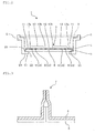
- FIG. 1 is a plan view showing the outline of the induction heating container according to this embodiment
- FIG. 2 is a schematic end elevation taken along the line A-A in FIG. 1 .
- the induction heating container 1 shown in FIGs. 1 and 2 is provided with a container main body 2 formed of a non-conductive material and an induction heat generator 3 attached to the inside of the container main body.
- the induction heat generator 3 is formed of a laminated body that includes a conductor layer 4 that generates heat when eddy current is induced by high-frequency magnetic field and a heat-seal layer 5 that has heat-sealing properties for the container main body 2.
- the induction heating container 1 is generally used on a commercially available electromagnetic cocker. Therefore, it is preferred that the sizes of the container main body 2 and the induction heat generator 3 be set according to the size of the heating coil provided in the electromagnetic cocker used.
- a general heating coil provided in a commercially available household electromagnetic cocker has an inner diameter of about 5 cm and an outer diameter of about 20 cm. In the case of an electromagnetic cocker for business use, a larger heating coil may be used. The size thereof is appropriately set according to the electromagnetic cocker that is supposed to be used.
- the container main body 2 is formed of a non-conductive material.
- a synthetic resin material such as a polystyrene-based resin such as polystyrene, a polyester-based resin such as polyethylene terephthalate, a polyolefin-based resin such as polypropylene, a polyamide-based resin or the like can preferably be used.
- the container main body 2 may be of a single layer structure or a multilayer structure obtained by combining these resins with one another or by combining these resins with other functional resins.
- paper, glass or the like can also be used as the non-conductive material, taking into consideration heat sealing with the heat-seal layer 5 in the induction heat generator 3, it is preferred that the inner surface thereof be coated with the above-mentioned synthetic resin.
- the shape of the container main body 2 is not limited to that shown in the figure. Various shapes can be selected such that the shape in the planer view is square, rectangular oblong, circle, elliptical or the like. In the shown example, in the planer view, the shape of the container main body 2 is almost square, and a step is provided in the vicinity of an opening at the upper end such that a tray 9 on which foodstuff is mounted can be supported or fitted. Although not particularly shown, a configuration is possible in which, on the tray 9 that is supported by or fitted to the container main body 2, another induction heating container 1 is stacked.
- the induction heat generator 3 has an almost circular flat plate form, and is attached to a bottom surface 20 of the container main body 2 in an almost circular flat plate form.
- a circle is most effective in respect of properties of eddy current induced.
- the shape of the container it may be square or elliptical.
- a rising part may be provided along the side wall of the container main body 2.
- the conductive material forming the conductor layer 4 of the induction heat generator 3 various conductive materials that generate heat by induction heating caused by high-frequency magnetic field such as a metal including aluminum, nickel, gold, silver, copper, platinum, iron, cobalt, tin and zinc, or alloys thereof can be used. More specifically, when aluminum is used as a conductive material, for example, the conductor layer 4 can be formed by using aluminum foil having a thickness of about 0.10 to 100 ⁇ m, more preferably 1 to 40 ⁇ m.
- the induction heat generator 3 when the induction heat generator 3 is attached to the container main body 2, it becomes easy to adapt the induction heat generator 3 to the shape of the container main body 2 by subjecting the induction heat generator 3 to three-dimensional processing, e.g. folding along a bottom surface 21 or the side wall of the container main body 2, or the like.
- the heat-seal layer 5 of the induction heat generator 3 is not particularly restricted as long as it has heat-sealing properties for the container main body 2.
- the heat-seal layer 5 can be appropriately selected according to a non-conductive material forming the container main body 2.
- a synthetic resin material similar to the synthetic resin material used for the container main body 2 can be used.
- polypropylene that is easy to be processed by molding, has good heat-sealing properties and an adequate heat resistance.
- the conductor layer 4 and the heat-seal layer 5 can be laminated directly or through an adequate adhesive by a known laminating technology.
- the induction heat generator 3 By configuring the induction heat generator 3 as a laminated body, since conventionally known technologies for producing a multilayer film or a multilayer sheet can be applied, the production of the induction heat generator 3 and the induction heating container 1 that is provided with the induction heat generator 3 is facilitated.
- a fuse function part 7 that is broken selectively under specific circumstances (such as empty boiling) is provided.
- Two fuse function parts 7 are radially provided on an extension of the center line that passes a shape center 8 of the induction heat generator 3 with a prescribed distance being provided from the shape center 8.
- the fuse function part 7 a technology disclosed in Patent Document 1 or JP-A-2010-044929 can be used, for example.
- the induction heat generator 3 is separated in the radial direction, and edges of the thus separated generator are abutted to each other or superimposed one on another to allow the conductor layers 4 are brought into contact and re-bonded.
- FIG. 3 which is a schematic end elevation view taken along line B-B in FIG. 1 , shows one example of such fuse function part 7.
- the edge part sides of the separated conductor layer 4 rises, and the edges thereof are aligned, superimposed one on another, and bonded.
- the heat-seal layer 5 in the corresponding part is peeled off.
- known technologies can be used; for example, a technology disclosed in JP-H07-296963 in which a narrow part in which the width in the radial direction becomes locally shortest is provided from the center to the outer periphery of the heat generator, whereby eddy current is concentrated in the narrow part to allow the temperature of the narrow part to be higher than that of other parts, a technology disclosed in JP-A-2007-330391 in which the radial direction of a heat generator is subjected to mountain folding processing in the radial direction to form a projection, and the projection is exposed from the liquid surface before other parts are exposed.
- an eddy current control part 6 that is formed by cutting the conductor layer 4 along the circumferential direction.
- a plurality of eddy current control parts 6 are provided such that they avoid the fuse function part 7 and that they are spaced from each other in the radial direction.
- the eddy current control parts 6 are provided by four cutting lines 13 in total in a region slightly nearer to the outer periphery of the induction heat generator 3 (a main heating area10, mentioned later).
- the edges of the cutting lines 13 that form the eddy current control part 6 serve as a starting point where bubbles are generated when an object to be heated such as water is boiled. Accordingly, at the time of boiling, a large amount of small bubbles is continuously generated as in the case where a boiling bubble stone is put, whereby an effect is exhibited that abrupt generation of large bubbles is prevented.
- the eddy current control part 6 controls the eddy current induced in the conductor layer 4, and enables uniform heating, whereby occurrence of bumping is suppressed.
- Eddy current is strongly induced in accordance with the shape of a heating coil provided in an electromagnetic cooker on which the induction heating container 1 is mounted.
- the current density distribution thereof is not uniform in the radial direction, and has a current density peak at a position slightly closer to the outer periphery than the center of the radial direction, and as a result, a corresponding position of the conductor layer 4 is strongly heated.
- the cutting line 13 that forms the eddy current control part 6 is, as shown in the schematic end elevation in FIG. 4(a) , obtained by cutting the conductor layer 4 of the laminated bodies forming the induction heat generator 3. No current is flown in a direction crossing the cutting line 13. By forming the cutting line 13 that extends in the circumferential direction in order to prevent eddy current from being concentrated in a part closer to the outside, eddy current can be aligned to attain uniform heating.
- the eddy current control part 6 which is formed by the cutting line 13 be provided.
- the eddy current control parts 6 be provided densely in a part closer to the outer periphery as compared with a case where they are arranged uniformly in the radial direction.
- no eddy current control part 6 is provided in the fuse function part 7 in order not to impede its function of being selectively broken down at the time of overheating.
- the shape of the cutting line 13 that constitutes the eddy current control part 6 is not limited to a circle or an arc around the shape center 8 of the induction heat generator 3. It can be appropriately altered taking into account factors that affect the state of eddy current induced, such as the shape of a heating coil of an electromagnetic cooker that is supposed to be used or the entire shape of the induction heat generator 3.
- the induction heat generator 3 is separated into the main heating region 10 on the center side and the peripheral region 11 on the outer periphery side by a first radial direction cutting line 13a that cuts the conductor layer 4 circularly (see FIG. 2 ).
- a first radial direction cutting line 13a that cuts the conductor layer 4 circularly (see FIG. 2 ).
- eddy current since eddy current does not flow in the direction crossing the cutting line 13, eddy current is formed independently for each region separated.
- strong eddy current is induced around the shape center 8 of the induction heat generator 3 (mounted on the center of the heating coil), therefore the main heating area10 is heated most efficiently. All of the plural eddy current control parts 6 and the fuse function part 7 are provided in the main heating area 10.
- the entire induction heat generator 3 can be regarded as the main heating area
- the peripheral area 11 is separated into plural small areas by a circumferential cutting line 13c that extends in the radial direction.
- a circumferential cutting line 13c that extends in the radial direction.
- a central adjustment area 12 is formed by a second radial direction cutting line 13b that cuts the conductor layer 4 circularly (see FIG. 2 ).
- the central adjustment area 12 is separated into plural areas in the circumferential direction by a circumferential direction cutting line 13c. Due to such a configuration, as in the case of the peripheral area 11, strong eddy current is not formed in the central adjustment area 12.
- Eddy current induced in the region including the shape center 8 is not so strong.
- the current density distribution thereof is slightly unstable and may disturb eddy current that flows in the outer side, and hence, it is preferable to separate the conductor layer 4 in this area from the main heating area.
- the induction heat generator 3 is attached in such a manner that the heat-seal layer 5 in the peripheral region 11 is heat-sealed to a heat seal site 21 of the bottom surface 20 of the container main body 2.
- a through hole 22 is provided, the induction heat generator 3 is exposed, and the through hole 22 is sealed by the induction heat generator 3.
- the bottom surface 20 of the container main body 2 may be deformed by bending during cooking with heat, and may be mounted on an electromagnetic cooker in an unstable manner.
- the container by removing the bottom surface from a position right below the main heating area 10 of the induction heat generator 3, of which the temperature becomes highest, the container is prevented from being deformed by bending.
- a grounding part 23 surrounding the through hole 22 has a higher rigidity than that of the induction heat generator 3, even if the induction heat generator 3 that is exposed from the through hole 22 is bent, it can keep a stable posture.
- the container main body 2 is not limited to the shown example. It may be of a common configuration in which the bottom surface 20 is closed, that is a general form. Attachment of the induction heat generator 3 in that case, the technology disclosed in Patent Document 2 can also be used. Further, similar effects can be obtained by providing a through hole in the middle of the induction heat generator 3 instead of the central adjusting region 12. In addition, a convection hole that accelerates the convection of an object to be heated may appropriately be formed by penetration.
- the induction heating container 1 having such a configuration is able to accommodate a liquid object to be heated (water, soup, or the like) and is able to heat the object to be heated by mounting on an electromagnetic cooker. Under specific circumstances where heating starts without accommodating an object to be heated or the container is left until a liquid object to be heated is evaporated, or the like, the fuse function part 7 is broken, and the break-down of the fuse part 7 is detected by a safety device of the electromagnetic cocker, then the heating is terminated. As a result, damage on the container can be prevented.
- the electromagnetic induction heating container 1 is used for steam cocking as a disposable container, or the like, the fuse function part 7 can be used like a cooking timer.
- the edges of the cutting lines 13 that constitute the eddy current control part 6 serve as a starting point at which an object to be heated such as water boils to allow bubbles to be generated, and a large amount of small bubbles is continuously formed, thus preventing sudden formation of large bubbles.
- an object to be heated such as water boils to allow bubbles to be generated, and a large amount of small bubbles is continuously formed, thus preventing sudden formation of large bubbles.
- disturbance or deviation of eddy current is prevented, whereby uniform heating becomes possible, leading to effective suppression of bumping.
- the eddy current control part 6 is provided such that it avoids the fuse function part 7, it can be used safely without hindering operation of the fuse function part 7.
- FIG. 5 is a plan view showing the outline of the induction heating container of this embodiment and FIG. 6 is an end elevation taken along line C-C in FIG. 5 .
- the induction heating container 1 shown in FIG. 5 and FIG. 6 is provided with the container main body 2 formed of a non-conductive material and the induction heat generator 3 that is attached to the closed bottom surface 20 of this container main body 2.
- the bottom surface 20 of the container main body 2 is almost square.
- the container main body 2 is configured such that it can accommodate a liquid object to be heated such as water by allowing a side wall part to rise such that it surrounds this bottom surface 20.
- the shape of the bottom surface 20 is not limited to that shown in the figures.
- the shape of the bottom surface 20 may be rectangular or circular.
- the shape may be a polygon such as a triangle, a pentagon and a hexagon.
- the overall shape of the container main body 2 it may have various shapes taking easiness in handling or the like into account.
- the dimensions of the container main body 2 and the induction heat generator 3 are set adequately.
- This embodiment differs from the above-mentioned first embodiment in that the container main body 2 of which the bottom surface 20 is closed is used, and the induction heat generator 3 is attached to the bottom surface 20 of the container main body 2 and the features changed in accordance therewith.
- Other features are the same as those in the above-mentioned first embodiment, and hence a duplicated explanation is omitted.
- the induction heat generator 3 In attaching the induction heat generator 3 to the bottom surface 20 of the container main body 2, it is preferred that the induction heat generator 3 be attached such that it is spaced from the bottom surface 20 of the container main body 2.
- a liquid object to be heated such as water accommodated within the container main body 2 spreads to a gap between the induction heat generator 3 and the bottom surface 20 of the container main body 2.
- a through hole 3a that is cut in an arbitrary shape such as circular or elliptical or a slit-like cut is provided in the middle or its vicinity of the induction heat generator 3 so that convection is accelerated to prevent an object to be heated from stagnating in the backside of the induction heat generator 3.
- the induction heat generator 3 may be heat-sealed to a supporting part 24 that projects from the bottom surface 20 of the container main body 2, for example.
- the conductor layer 4 is separated into the main heating region 10 and the peripheral region 11 (on the outer peripheral side) by the first radial direction cutting line 13a, the peripheral area 11 is separated into plural small areas by the circumferential direction cutting line 13c, and these regions are heat-sealed to the container main body 2 in the heat-seal layer 5 in the peripheral area 11.
- heat sealing to the supporting part 24 be conducted in the heat seal-layer 5 in the peripheral area 11.
- the induction heat generator 3 is heat-sealed to the supporting part 24 in the heat-seal layer 5 of the central adjustment region 12. Further, it is preferred that, also in the main heating region 10 of the induction heat generator 3, small areas separated from the main heating area 10 be formed by surrounding a specific range of the conductor layer 4 by a cutting line 13d and that heat sealing to the supporting part 24 be conducted by the heat-seal layer 5 in these small areas. As a result, heat transmission from the induction heat generator 3 to the container main body 2 is suppressed, whereby deformation or burning of the container main body 2 can be prevented.
- induction heat generator 3 By attaching the induction heat generator 3 to the container main body 2 also in the central adjustment area 12 or the main heating area 10, floating or waving of the induction heat generator 3 due to convection or flow of an object to be heated or repulsion with the heating coil can be suppressed, whereby more stable heating becomes possible.
- the shape or the dimension thereof is taken into consideration so that eddy current that is induced in the main heating area is not greatly disturbed.
- the cutting lines 13, 13a, 13b, 13c, 13d and 13e are indicated as those obtained by separating completely the conductor layer 4 in the thickness direction.
- these cutting lines may be in the state where the conductor layer 4 is connected thereto with a part in the thickness direction being remained.
- this edge exposed part serves as a starting point where bubbles are generated when an object to be heated such as water boils, whereby occurrence of bumping is suppressed by preventing abrupt generation of large bubbles, the conductor layer 4 is not necessarily broken completely in the edge exposed part.
- the induction heating container according to the present invention can be used as a container that is able to heat an object to be heated by a commercially available an electromagnetic cooker.
Landscapes
- Physics & Mathematics (AREA)
- Electromagnetism (AREA)
- Engineering & Computer Science (AREA)
- Food Science & Technology (AREA)
- Cookers (AREA)
- Package Specialized In Special Use (AREA)
Claims (10)
- Induktionserwärmungsbehälter, in dem ein Induktionswärmeerzeuger (3) an dem Inneren eines Behälterhauptkörpers (2) befestigt ist, der aus einem nicht leitfähigen Material hergestellt ist, um das Kochen durch Erwärmen durch einen elektromagnetischen Kocher zu ermöglichen, wobei der Induktionswärmegenerator (3) aufweist: einen laminierten Körper mit einer Leiterschicht (4), die durch Induktion von Wirbelstrom durch hochfrequentes Magnetfeld Wärme erzeugt, und einer Heisssiegelschicht (5), die dem Behälterhauptkörper Heisssiegeleigenschaften verleiht, und dadurch gekennzeichnet ist, dass der Induktionswärmegenerator (3) ein Sicherungsfunktionsteil (7) aufweist, welches selektiv unter spezifischen Umständen gebrochen wird, und dass eine Vielzahl von Wirbelstromsteuerteilen (6) vorgesehen sind, die durch Schneiden der Leiterschicht (4) entlang der Umfangsrichtung erhalten werden, so dass sie ein Sicherungsfunktionsteil (7) vermeiden und dass sie voneinander in radialer Richtung beabstandet sind.
- Induktionserwärmungsbehälter nach Anspruch 1, dadurch gekennzeichnet, dass jeder Wirbelstromsteuerteil (6) aus einem durch Schneiden der Leiterschicht (4) in der Dickenrichtung erhaltenen, Rand exponierten Teil gebildet ist.
- Induktionserwärmungsbehälter nach Anspruch 1 oder 2, dadurch gekennzeichnet, dass in dem Induktionswärmegenerator die Leiterschicht (4) so geschnitten wird, dass sie einen Hauptheizbereich bildet, der den Wirbelstromsteuerteil (6) und einen Umfangsbereich umfasst, der sich auf der äusseren Umfangsseite des Hauptheizbereichs befindet, und dass eine Heisssiegelschicht (5) des Umfangsbereichs mit dem Behälterhauptkörper heissversiegelt verbunden ist.
- Induktionserwärmungsbehälter nach Anspruch 3, dadurch gekennzeichnet, dass in dem Hauptheizbereich die Leiterschicht (4) geschnitten ist, um kleine, vom Hauptheizbereich getrennte Bereiche auszubilden, und dass die Heisssiegelschicht (5) der kleinen Bereiche mit dem Behälterhauptkörper heissversiegelt ist.
- Induktionserwärmungsbehälter nach Anspruch 3, dadurch gekennzeichnet, dass in dem Hauptheizbereich Schnittlinien (13) in Form von in radialer Richtung sich erstreckenden Liniensegmenten ausgebildet sind, die in der Leiterschicht (4) ausgebildet ist, und dass ein Teil der Heisssiegelschicht (5), der die Schnittlinie (13) überlappt, mit dem Behälterhauptkörper heissversiegelt ist.
- Induktionserwärmungsbehälter nach irgendeinem der Ansprüche 3 bis 5, dadurch gekennzeichnet, dass die Leiterschicht (4) im Umfangsbereich in Umfangsrichtung weiter getrennt ist.
- Induktionserwärmungsbehälter nach irgendeinem der Ansprüche 3 bis 6, dadurch gekennzeichnet, dass in dem Induktionserwärmungsbehälter die Leiterschicht (4) so geschnitten ist, dass ein zentraler Einstellbereich auf der inneren Umfangsseite des Hauptheizbereichs ausgebildet ist.
- Induktionserwärmungsbehälter nach Anspruch 7, dadurch gekennzeichnet, dass die Leiterschicht (4) in dem zentralen Einstellbereich in Umfangsrichtung weiter getrennt ist.
- Induktionserwärmungsbehälter nach einem der Ansprüche 3 bis 8, dadurch gekennzeichnet, dass der Wirbelstromsteuerteil (6) näher am Aussenumfang des Hauptheizbereiches angeordnet ist.
- Induktionserwärmungsbehälter nach einem der Ansprüche 3 bis 9, dadurch gekennzeichnet, dass der Behälterhauptkörper (2) ein Durchgangsloch in einer Bodenfläche auf der inneren Umfangsseite von einem Teil aufweist, in dem der Umfangsbereich des Induktionswärmeerzeugers (3) heissversiegelt ist, und das Durchgangsloch durch den Induktionswärmeerzeuger abgedichtet ist.
Applications Claiming Priority (3)
| Application Number | Priority Date | Filing Date | Title |
|---|---|---|---|
| JP2012216899 | 2012-09-28 | ||
| JP2013047816A JP6127593B2 (ja) | 2012-09-28 | 2013-03-11 | 誘導加熱容器 |
| PCT/JP2013/005511 WO2014050029A1 (ja) | 2012-09-28 | 2013-09-18 | 誘導加熱容器 |
Publications (3)
| Publication Number | Publication Date |
|---|---|
| EP2901899A1 EP2901899A1 (de) | 2015-08-05 |
| EP2901899A4 EP2901899A4 (de) | 2016-05-25 |
| EP2901899B1 true EP2901899B1 (de) | 2017-05-10 |
Family
ID=50387472
Family Applications (1)
| Application Number | Title | Priority Date | Filing Date |
|---|---|---|---|
| EP13842779.4A Not-in-force EP2901899B1 (de) | 2012-09-28 | 2013-09-18 | Induktionserwärmungsbehälter |
Country Status (5)
| Country | Link |
|---|---|
| US (1) | US9736891B2 (de) |
| EP (1) | EP2901899B1 (de) |
| JP (1) | JP6127593B2 (de) |
| CN (1) | CN104619216B (de) |
| WO (1) | WO2014050029A1 (de) |
Families Citing this family (14)
| Publication number | Priority date | Publication date | Assignee | Title |
|---|---|---|---|---|
| JP5737360B2 (ja) * | 2013-10-23 | 2015-06-17 | 東洋製罐グループホールディングス株式会社 | 誘導加熱発熱体、及び誘導加熱容器 |
| WO2015059900A1 (ja) * | 2013-10-23 | 2015-04-30 | 東洋製罐グループホールディングス株式会社 | 誘導加熱発熱体、及び誘導加熱容器 |
| US20150201800A1 (en) * | 2014-01-17 | 2015-07-23 | Jason Ryu | Cooking device and method with temperature control |
| JP5954482B1 (ja) * | 2015-10-21 | 2016-07-20 | 東洋製罐グループホールディングス株式会社 | 誘導加熱発熱体、及び誘導加熱容器 |
| JP2016171979A (ja) * | 2015-03-16 | 2016-09-29 | 東洋製罐グループホールディングス株式会社 | 誘導加熱発熱体、及び誘導加熱容器 |
| CN107249405A (zh) * | 2015-03-16 | 2017-10-13 | 东洋制罐集团控股株式会社 | 感应加热发热体以及感应加热容器 |
| WO2016147534A1 (ja) * | 2015-03-16 | 2016-09-22 | 東洋製罐グループホールディングス株式会社 | 誘導加熱発熱体、及び誘導加熱容器 |
| JP6481470B2 (ja) * | 2015-03-31 | 2019-03-13 | 東洋製罐グループホールディングス株式会社 | 誘導加熱発熱体、及び誘導加熱容器 |
| US11665790B2 (en) * | 2016-12-22 | 2023-05-30 | Whirlpool Corporation | Induction burner element having a plurality of single piece frames |
| ES2713379A1 (es) * | 2017-11-20 | 2019-05-21 | Bsh Electrodomesticos Espana Sa | Procedimiento para el montaje de un sistema de coccion |
| CN109452873B (zh) * | 2018-06-29 | 2022-06-21 | 浙江苏泊尔家电制造有限公司 | 用于电烹饪器具的内锅、电烹饪器具和制造内锅的方法 |
| CN108980919A (zh) * | 2018-08-13 | 2018-12-11 | 中山市雅乐思商住电器有限公司 | 一种感应加热容器 |
| CN112628808A (zh) * | 2020-12-04 | 2021-04-09 | 佛山市合世纪科技有限公司 | 一种食品加热方法、装置、存储介质和加热装置 |
| JP7841780B1 (ja) * | 2025-09-02 | 2026-04-07 | 株式会社丸善トレー | 食品用容器 |
Family Cites Families (20)
| Publication number | Priority date | Publication date | Assignee | Title |
|---|---|---|---|---|
| JPH07303569A (ja) * | 1993-08-12 | 1995-11-21 | Eisuke Ishida | 電磁調理器用食器 |
| JP2939555B2 (ja) * | 1993-12-27 | 1999-08-25 | 島田理化工業株式会社 | 電磁調理器 |
| JPH07213420A (ja) * | 1994-01-31 | 1995-08-15 | Toshiba Home Technol Corp | 電磁誘導加熱式容器 |
| DE4412944A1 (de) * | 1994-04-15 | 1995-10-19 | Vesta Ag & Co Ohg | Topfförmiges Gar- und/oder Kochgerät |
| JP2873164B2 (ja) | 1994-04-28 | 1999-03-24 | 日清食品株式会社 | 安全機構付き電磁調理用容器 |
| JPH09117374A (ja) * | 1995-10-25 | 1997-05-06 | Kobe Steel Ltd | 電磁調理器用容器 |
| JP2851821B2 (ja) * | 1996-04-16 | 1999-01-27 | 東海理化販売株式会社 | 電磁調理用鍋 |
| JP2003051375A (ja) * | 2001-08-08 | 2003-02-21 | Matsushita Electric Ind Co Ltd | 電磁誘導加熱調理器用の被加熱調理器具 |
| JP4159426B2 (ja) * | 2003-08-05 | 2008-10-01 | 株式会社大慶 | 電磁調理器用鍋 |
| JP4826345B2 (ja) * | 2006-06-05 | 2011-11-30 | 東洋製罐株式会社 | 包装容器 |
| JP2007330353A (ja) | 2006-06-13 | 2007-12-27 | Eisuke Ishida | 電磁調理器用加熱体と電磁調理器用食器 |
| JP2007330391A (ja) | 2006-06-13 | 2007-12-27 | Toyo Seikan Kaisha Ltd | 誘導加熱調理容器 |
| WO2008001425A1 (en) * | 2006-06-26 | 2008-01-03 | Toyo Seikan Kaisha, Ltd. | Container for electromagnetic cookers |
| JP5102508B2 (ja) * | 2007-02-07 | 2012-12-19 | 東洋製罐株式会社 | 誘導加熱調理容器 |
| JP5070870B2 (ja) * | 2007-02-09 | 2012-11-14 | 東洋製罐株式会社 | 誘導加熱発熱体、及び誘導加熱容器 |
| JP5386882B2 (ja) | 2008-08-12 | 2014-01-15 | 東洋製罐グループホールディングス株式会社 | 誘導加熱発熱体、及び誘導加熱容器 |
| JP5253938B2 (ja) * | 2008-09-09 | 2013-07-31 | 東洋製罐グループホールディングス株式会社 | 誘導加熱容器 |
| EP2408262B1 (de) * | 2009-03-13 | 2019-06-05 | Panasonic Corporation | Kochvorrichtung mit induktionserhitzung und küchengerät damit |
| FI124407B (fi) * | 2009-11-26 | 2014-08-15 | Iittala Group Oy Ab | Induktiokuumennukseen soveltuva keittoastia ja menetelmä sen valmistamiseksi |
| JP2012110636A (ja) * | 2010-11-29 | 2012-06-14 | Panasonic Corp | 誘導加熱調理器用調理容器 |
-
2013
- 2013-03-11 JP JP2013047816A patent/JP6127593B2/ja active Active
- 2013-09-18 US US14/425,661 patent/US9736891B2/en not_active Expired - Fee Related
- 2013-09-18 WO PCT/JP2013/005511 patent/WO2014050029A1/ja not_active Ceased
- 2013-09-18 CN CN201380047024.6A patent/CN104619216B/zh not_active Expired - Fee Related
- 2013-09-18 EP EP13842779.4A patent/EP2901899B1/de not_active Not-in-force
Also Published As
| Publication number | Publication date |
|---|---|
| JP6127593B2 (ja) | 2017-05-17 |
| US9736891B2 (en) | 2017-08-15 |
| EP2901899A1 (de) | 2015-08-05 |
| CN104619216A (zh) | 2015-05-13 |
| US20150215995A1 (en) | 2015-07-30 |
| WO2014050029A1 (ja) | 2014-04-03 |
| JP2014079560A (ja) | 2014-05-08 |
| CN104619216B (zh) | 2017-03-08 |
| EP2901899A4 (de) | 2016-05-25 |
Similar Documents
| Publication | Publication Date | Title |
|---|---|---|
| US9736891B2 (en) | Induction heating container | |
| JP2008194139A (ja) | 誘導加熱発熱体、及び誘導加熱容器 | |
| CN105848534B (zh) | Ih烹调器用的发热片及ih烹调器用的加热烹调装置 | |
| JP6090155B2 (ja) | 誘導加熱発熱体、及び誘導加熱容器 | |
| JP5155637B2 (ja) | 誘導加熱容器 | |
| JP5102508B2 (ja) | 誘導加熱調理容器 | |
| JP5737360B2 (ja) | 誘導加熱発熱体、及び誘導加熱容器 | |
| JP2016171979A (ja) | 誘導加熱発熱体、及び誘導加熱容器 | |
| CN105658118B (zh) | 感应加热发热体以及感应加热容器 | |
| JP5954482B1 (ja) | 誘導加熱発熱体、及び誘導加熱容器 | |
| JP5253938B2 (ja) | 誘導加熱容器 | |
| JP4826345B2 (ja) | 包装容器 | |
| JP6260434B2 (ja) | 誘導加熱発熱体、及び誘導加熱容器 | |
| JP5726398B2 (ja) | 電磁調理器用容器 | |
| JP6481470B2 (ja) | 誘導加熱発熱体、及び誘導加熱容器 | |
| WO2018116704A1 (ja) | Ih調理器用発熱シート | |
| JP6150029B1 (ja) | Ih調理器用積層発熱シート | |
| JP6052335B2 (ja) | 誘導加熱発熱体 | |
| WO2016147534A1 (ja) | 誘導加熱発熱体、及び誘導加熱容器 | |
| CN107249405A (zh) | 感应加热发热体以及感应加热容器 | |
| JP2014176609A (ja) | 誘導加熱容器 | |
| JP2009045256A (ja) | 過加熱防止機能付き電磁調理器用容器 |
Legal Events
| Date | Code | Title | Description |
|---|---|---|---|
| PUAI | Public reference made under article 153(3) epc to a published international application that has entered the european phase |
Free format text: ORIGINAL CODE: 0009012 |
|
| 17P | Request for examination filed |
Effective date: 20150311 |
|
| AK | Designated contracting states |
Kind code of ref document: A1 Designated state(s): AL AT BE BG CH CY CZ DE DK EE ES FI FR GB GR HR HU IE IS IT LI LT LU LV MC MK MT NL NO PL PT RO RS SE SI SK SM TR |
|
| AX | Request for extension of the european patent |
Extension state: BA ME |
|
| DAX | Request for extension of the european patent (deleted) | ||
| RA4 | Supplementary search report drawn up and despatched (corrected) |
Effective date: 20160425 |
|
| RIC1 | Information provided on ipc code assigned before grant |
Ipc: H05B 6/12 20060101ALI20160419BHEP Ipc: A47J 27/00 20060101AFI20160419BHEP |
|
| GRAP | Despatch of communication of intention to grant a patent |
Free format text: ORIGINAL CODE: EPIDOSNIGR1 |
|
| STAA | Information on the status of an ep patent application or granted ep patent |
Free format text: STATUS: GRANT OF PATENT IS INTENDED |
|
| INTG | Intention to grant announced |
Effective date: 20161216 |
|
| GRAS | Grant fee paid |
Free format text: ORIGINAL CODE: EPIDOSNIGR3 |
|
| GRAA | (expected) grant |
Free format text: ORIGINAL CODE: 0009210 |
|
| STAA | Information on the status of an ep patent application or granted ep patent |
Free format text: STATUS: THE PATENT HAS BEEN GRANTED |
|
| AK | Designated contracting states |
Kind code of ref document: B1 Designated state(s): AL AT BE BG CH CY CZ DE DK EE ES FI FR GB GR HR HU IE IS IT LI LT LU LV MC MK MT NL NO PL PT RO RS SE SI SK SM TR |
|
| REG | Reference to a national code |
Ref country code: GB Ref legal event code: FG4D |
|
| REG | Reference to a national code |
Ref country code: AT Ref legal event code: REF Ref document number: 891400 Country of ref document: AT Kind code of ref document: T Effective date: 20170515 Ref country code: CH Ref legal event code: EP |
|
| REG | Reference to a national code |
Ref country code: IE Ref legal event code: FG4D |
|
| REG | Reference to a national code |
Ref country code: DE Ref legal event code: R096 Ref document number: 602013021093 Country of ref document: DE |
|
| REG | Reference to a national code |
Ref country code: NL Ref legal event code: MP Effective date: 20170510 |
|
| REG | Reference to a national code |
Ref country code: LT Ref legal event code: MG4D |
|
| REG | Reference to a national code |
Ref country code: FR Ref legal event code: PLFP Year of fee payment: 5 |
|
| REG | Reference to a national code |
Ref country code: AT Ref legal event code: MK05 Ref document number: 891400 Country of ref document: AT Kind code of ref document: T Effective date: 20170510 |
|
| PG25 | Lapsed in a contracting state [announced via postgrant information from national office to epo] |
Ref country code: LT Free format text: LAPSE BECAUSE OF FAILURE TO SUBMIT A TRANSLATION OF THE DESCRIPTION OR TO PAY THE FEE WITHIN THE PRESCRIBED TIME-LIMIT Effective date: 20170510 Ref country code: HR Free format text: LAPSE BECAUSE OF FAILURE TO SUBMIT A TRANSLATION OF THE DESCRIPTION OR TO PAY THE FEE WITHIN THE PRESCRIBED TIME-LIMIT Effective date: 20170510 Ref country code: FI Free format text: LAPSE BECAUSE OF FAILURE TO SUBMIT A TRANSLATION OF THE DESCRIPTION OR TO PAY THE FEE WITHIN THE PRESCRIBED TIME-LIMIT Effective date: 20170510 Ref country code: GR Free format text: LAPSE BECAUSE OF FAILURE TO SUBMIT A TRANSLATION OF THE DESCRIPTION OR TO PAY THE FEE WITHIN THE PRESCRIBED TIME-LIMIT Effective date: 20170811 Ref country code: NO Free format text: LAPSE BECAUSE OF FAILURE TO SUBMIT A TRANSLATION OF THE DESCRIPTION OR TO PAY THE FEE WITHIN THE PRESCRIBED TIME-LIMIT Effective date: 20170810 Ref country code: AT Free format text: LAPSE BECAUSE OF FAILURE TO SUBMIT A TRANSLATION OF THE DESCRIPTION OR TO PAY THE FEE WITHIN THE PRESCRIBED TIME-LIMIT Effective date: 20170510 Ref country code: ES Free format text: LAPSE BECAUSE OF FAILURE TO SUBMIT A TRANSLATION OF THE DESCRIPTION OR TO PAY THE FEE WITHIN THE PRESCRIBED TIME-LIMIT Effective date: 20170510 |
|
| PG25 | Lapsed in a contracting state [announced via postgrant information from national office to epo] |
Ref country code: IS Free format text: LAPSE BECAUSE OF FAILURE TO SUBMIT A TRANSLATION OF THE DESCRIPTION OR TO PAY THE FEE WITHIN THE PRESCRIBED TIME-LIMIT Effective date: 20170910 Ref country code: NL Free format text: LAPSE BECAUSE OF FAILURE TO SUBMIT A TRANSLATION OF THE DESCRIPTION OR TO PAY THE FEE WITHIN THE PRESCRIBED TIME-LIMIT Effective date: 20170510 Ref country code: LV Free format text: LAPSE BECAUSE OF FAILURE TO SUBMIT A TRANSLATION OF THE DESCRIPTION OR TO PAY THE FEE WITHIN THE PRESCRIBED TIME-LIMIT Effective date: 20170510 Ref country code: RS Free format text: LAPSE BECAUSE OF FAILURE TO SUBMIT A TRANSLATION OF THE DESCRIPTION OR TO PAY THE FEE WITHIN THE PRESCRIBED TIME-LIMIT Effective date: 20170510 Ref country code: SE Free format text: LAPSE BECAUSE OF FAILURE TO SUBMIT A TRANSLATION OF THE DESCRIPTION OR TO PAY THE FEE WITHIN THE PRESCRIBED TIME-LIMIT Effective date: 20170510 Ref country code: PL Free format text: LAPSE BECAUSE OF FAILURE TO SUBMIT A TRANSLATION OF THE DESCRIPTION OR TO PAY THE FEE WITHIN THE PRESCRIBED TIME-LIMIT Effective date: 20170510 Ref country code: BG Free format text: LAPSE BECAUSE OF FAILURE TO SUBMIT A TRANSLATION OF THE DESCRIPTION OR TO PAY THE FEE WITHIN THE PRESCRIBED TIME-LIMIT Effective date: 20170810 |
|
| PG25 | Lapsed in a contracting state [announced via postgrant information from national office to epo] |
Ref country code: DK Free format text: LAPSE BECAUSE OF FAILURE TO SUBMIT A TRANSLATION OF THE DESCRIPTION OR TO PAY THE FEE WITHIN THE PRESCRIBED TIME-LIMIT Effective date: 20170510 Ref country code: CZ Free format text: LAPSE BECAUSE OF FAILURE TO SUBMIT A TRANSLATION OF THE DESCRIPTION OR TO PAY THE FEE WITHIN THE PRESCRIBED TIME-LIMIT Effective date: 20170510 Ref country code: EE Free format text: LAPSE BECAUSE OF FAILURE TO SUBMIT A TRANSLATION OF THE DESCRIPTION OR TO PAY THE FEE WITHIN THE PRESCRIBED TIME-LIMIT Effective date: 20170510 Ref country code: RO Free format text: LAPSE BECAUSE OF FAILURE TO SUBMIT A TRANSLATION OF THE DESCRIPTION OR TO PAY THE FEE WITHIN THE PRESCRIBED TIME-LIMIT Effective date: 20170510 Ref country code: SK Free format text: LAPSE BECAUSE OF FAILURE TO SUBMIT A TRANSLATION OF THE DESCRIPTION OR TO PAY THE FEE WITHIN THE PRESCRIBED TIME-LIMIT Effective date: 20170510 |
|
| REG | Reference to a national code |
Ref country code: DE Ref legal event code: R097 Ref document number: 602013021093 Country of ref document: DE |
|
| PG25 | Lapsed in a contracting state [announced via postgrant information from national office to epo] |
Ref country code: IT Free format text: LAPSE BECAUSE OF FAILURE TO SUBMIT A TRANSLATION OF THE DESCRIPTION OR TO PAY THE FEE WITHIN THE PRESCRIBED TIME-LIMIT Effective date: 20170510 Ref country code: SM Free format text: LAPSE BECAUSE OF FAILURE TO SUBMIT A TRANSLATION OF THE DESCRIPTION OR TO PAY THE FEE WITHIN THE PRESCRIBED TIME-LIMIT Effective date: 20170510 |
|
| PLBE | No opposition filed within time limit |
Free format text: ORIGINAL CODE: 0009261 |
|
| STAA | Information on the status of an ep patent application or granted ep patent |
Free format text: STATUS: NO OPPOSITION FILED WITHIN TIME LIMIT |
|
| 26N | No opposition filed |
Effective date: 20180213 |
|
| REG | Reference to a national code |
Ref country code: CH Ref legal event code: PL |
|
| PG25 | Lapsed in a contracting state [announced via postgrant information from national office to epo] |
Ref country code: MC Free format text: LAPSE BECAUSE OF FAILURE TO SUBMIT A TRANSLATION OF THE DESCRIPTION OR TO PAY THE FEE WITHIN THE PRESCRIBED TIME-LIMIT Effective date: 20170510 Ref country code: SI Free format text: LAPSE BECAUSE OF FAILURE TO SUBMIT A TRANSLATION OF THE DESCRIPTION OR TO PAY THE FEE WITHIN THE PRESCRIBED TIME-LIMIT Effective date: 20170510 |
|
| REG | Reference to a national code |
Ref country code: IE Ref legal event code: MM4A |
|
| REG | Reference to a national code |
Ref country code: BE Ref legal event code: MM Effective date: 20170930 |
|
| PG25 | Lapsed in a contracting state [announced via postgrant information from national office to epo] |
Ref country code: LU Free format text: LAPSE BECAUSE OF NON-PAYMENT OF DUE FEES Effective date: 20170918 |
|
| PG25 | Lapsed in a contracting state [announced via postgrant information from national office to epo] |
Ref country code: CH Free format text: LAPSE BECAUSE OF NON-PAYMENT OF DUE FEES Effective date: 20170930 Ref country code: IE Free format text: LAPSE BECAUSE OF NON-PAYMENT OF DUE FEES Effective date: 20170918 Ref country code: LI Free format text: LAPSE BECAUSE OF NON-PAYMENT OF DUE FEES Effective date: 20170930 |
|
| PG25 | Lapsed in a contracting state [announced via postgrant information from national office to epo] |
Ref country code: BE Free format text: LAPSE BECAUSE OF NON-PAYMENT OF DUE FEES Effective date: 20170930 |
|
| REG | Reference to a national code |
Ref country code: FR Ref legal event code: PLFP Year of fee payment: 6 |
|
| PG25 | Lapsed in a contracting state [announced via postgrant information from national office to epo] |
Ref country code: MT Free format text: LAPSE BECAUSE OF NON-PAYMENT OF DUE FEES Effective date: 20170918 |
|
| PG25 | Lapsed in a contracting state [announced via postgrant information from national office to epo] |
Ref country code: HU Free format text: LAPSE BECAUSE OF FAILURE TO SUBMIT A TRANSLATION OF THE DESCRIPTION OR TO PAY THE FEE WITHIN THE PRESCRIBED TIME-LIMIT; INVALID AB INITIO Effective date: 20130918 |
|
| PG25 | Lapsed in a contracting state [announced via postgrant information from national office to epo] |
Ref country code: CY Free format text: LAPSE BECAUSE OF FAILURE TO SUBMIT A TRANSLATION OF THE DESCRIPTION OR TO PAY THE FEE WITHIN THE PRESCRIBED TIME-LIMIT Effective date: 20170510 |
|
| PG25 | Lapsed in a contracting state [announced via postgrant information from national office to epo] |
Ref country code: MK Free format text: LAPSE BECAUSE OF FAILURE TO SUBMIT A TRANSLATION OF THE DESCRIPTION OR TO PAY THE FEE WITHIN THE PRESCRIBED TIME-LIMIT Effective date: 20170510 |
|
| PG25 | Lapsed in a contracting state [announced via postgrant information from national office to epo] |
Ref country code: TR Free format text: LAPSE BECAUSE OF FAILURE TO SUBMIT A TRANSLATION OF THE DESCRIPTION OR TO PAY THE FEE WITHIN THE PRESCRIBED TIME-LIMIT Effective date: 20170510 |
|
| PG25 | Lapsed in a contracting state [announced via postgrant information from national office to epo] |
Ref country code: PT Free format text: LAPSE BECAUSE OF FAILURE TO SUBMIT A TRANSLATION OF THE DESCRIPTION OR TO PAY THE FEE WITHIN THE PRESCRIBED TIME-LIMIT Effective date: 20170510 |
|
| PG25 | Lapsed in a contracting state [announced via postgrant information from national office to epo] |
Ref country code: AL Free format text: LAPSE BECAUSE OF FAILURE TO SUBMIT A TRANSLATION OF THE DESCRIPTION OR TO PAY THE FEE WITHIN THE PRESCRIBED TIME-LIMIT Effective date: 20170510 |
|
| PGFP | Annual fee paid to national office [announced via postgrant information from national office to epo] |
Ref country code: GB Payment date: 20230920 Year of fee payment: 11 |
|
| PGFP | Annual fee paid to national office [announced via postgrant information from national office to epo] |
Ref country code: FR Payment date: 20230928 Year of fee payment: 11 Ref country code: DE Payment date: 20230920 Year of fee payment: 11 |
|
| REG | Reference to a national code |
Ref country code: DE Ref legal event code: R119 Ref document number: 602013021093 Country of ref document: DE |
|
| GBPC | Gb: european patent ceased through non-payment of renewal fee |
Effective date: 20240918 |
|
| PG25 | Lapsed in a contracting state [announced via postgrant information from national office to epo] |
Ref country code: DE Free format text: LAPSE BECAUSE OF NON-PAYMENT OF DUE FEES Effective date: 20250401 |
|
| PG25 | Lapsed in a contracting state [announced via postgrant information from national office to epo] |
Ref country code: GB Free format text: LAPSE BECAUSE OF NON-PAYMENT OF DUE FEES Effective date: 20240918 |
|
| PG25 | Lapsed in a contracting state [announced via postgrant information from national office to epo] |
Ref country code: FR Free format text: LAPSE BECAUSE OF NON-PAYMENT OF DUE FEES Effective date: 20240930 |