EP2902113A1 - Procédé et dispositif d'isolation de lignes électriques - Google Patents
Procédé et dispositif d'isolation de lignes électriques Download PDFInfo
- Publication number
- EP2902113A1 EP2902113A1 EP14153573.2A EP14153573A EP2902113A1 EP 2902113 A1 EP2902113 A1 EP 2902113A1 EP 14153573 A EP14153573 A EP 14153573A EP 2902113 A1 EP2902113 A1 EP 2902113A1
- Authority
- EP
- European Patent Office
- Prior art keywords
- electrical line
- coating
- polymer particles
- unit
- electrical
- Prior art date
- Legal status (The legal status is an assumption and is not a legal conclusion. Google has not performed a legal analysis and makes no representation as to the accuracy of the status listed.)
- Granted
Links
Images


Classifications
-
- B—PERFORMING OPERATIONS; TRANSPORTING
- B05—SPRAYING OR ATOMISING IN GENERAL; APPLYING FLUENT MATERIALS TO SURFACES, IN GENERAL
- B05B—SPRAYING APPARATUS; ATOMISING APPARATUS; NOZZLES
- B05B5/00—Electrostatic spraying apparatus; Spraying apparatus with means for charging the spray electrically; Apparatus for spraying liquids or other fluent materials by other electric means
- B05B5/08—Plant for applying liquids or other fluent materials to objects
- B05B5/14—Plant for applying liquids or other fluent materials to objects specially adapted for coating continuously moving elongated bodies, e.g. wires, strips, pipes
-
- B—PERFORMING OPERATIONS; TRANSPORTING
- B05—SPRAYING OR ATOMISING IN GENERAL; APPLYING FLUENT MATERIALS TO SURFACES, IN GENERAL
- B05B—SPRAYING APPARATUS; ATOMISING APPARATUS; NOZZLES
- B05B14/00—Arrangements for collecting, re-using or eliminating excess spraying material
- B05B14/40—Arrangements for collecting, re-using or eliminating excess spraying material for use in spray booths
- B05B14/48—Arrangements for collecting, re-using or eliminating excess spraying material for use in spray booths specially adapted for particulate material
-
- B—PERFORMING OPERATIONS; TRANSPORTING
- B05—SPRAYING OR ATOMISING IN GENERAL; APPLYING FLUENT MATERIALS TO SURFACES, IN GENERAL
- B05B—SPRAYING APPARATUS; ATOMISING APPARATUS; NOZZLES
- B05B5/00—Electrostatic spraying apparatus; Spraying apparatus with means for charging the spray electrically; Apparatus for spraying liquids or other fluent materials by other electric means
- B05B5/08—Plant for applying liquids or other fluent materials to objects
- B05B5/081—Plant for applying liquids or other fluent materials to objects specially adapted for treating particulate materials
-
- H—ELECTRICITY
- H01—ELECTRIC ELEMENTS
- H01B—CABLES; CONDUCTORS; INSULATORS; SELECTION OF MATERIALS FOR THEIR CONDUCTIVE, INSULATING OR DIELECTRIC PROPERTIES
- H01B13/00—Apparatus or processes specially adapted for manufacturing conductors or cables
- H01B13/06—Insulating conductors or cables
- H01B13/16—Insulating conductors or cables by passing through or dipping in a liquid bath; by spraying
- H01B13/165—Insulating conductors or cables by passing through or dipping in a liquid bath; by spraying by spraying
-
- B—PERFORMING OPERATIONS; TRANSPORTING
- B05—SPRAYING OR ATOMISING IN GENERAL; APPLYING FLUENT MATERIALS TO SURFACES, IN GENERAL
- B05D—PROCESSES FOR APPLYING FLUENT MATERIALS TO SURFACES, IN GENERAL
- B05D1/00—Processes for applying liquids or other fluent materials
- B05D1/02—Processes for applying liquids or other fluent materials performed by spraying
- B05D1/12—Applying particulate materials
-
- B—PERFORMING OPERATIONS; TRANSPORTING
- B05—SPRAYING OR ATOMISING IN GENERAL; APPLYING FLUENT MATERIALS TO SURFACES, IN GENERAL
- B05D—PROCESSES FOR APPLYING FLUENT MATERIALS TO SURFACES, IN GENERAL
- B05D3/00—Pretreatment of surfaces to which liquids or other fluent materials are to be applied; After-treatment of applied coatings, e.g. intermediate treating of an applied coating preparatory to subsequent applications of liquids or other fluent materials
- B05D3/02—Pretreatment of surfaces to which liquids or other fluent materials are to be applied; After-treatment of applied coatings, e.g. intermediate treating of an applied coating preparatory to subsequent applications of liquids or other fluent materials by baking
- B05D3/0218—Pretreatment, e.g. heating the substrate
-
- B—PERFORMING OPERATIONS; TRANSPORTING
- B05—SPRAYING OR ATOMISING IN GENERAL; APPLYING FLUENT MATERIALS TO SURFACES, IN GENERAL
- B05D—PROCESSES FOR APPLYING FLUENT MATERIALS TO SURFACES, IN GENERAL
- B05D3/00—Pretreatment of surfaces to which liquids or other fluent materials are to be applied; After-treatment of applied coatings, e.g. intermediate treating of an applied coating preparatory to subsequent applications of liquids or other fluent materials
- B05D3/02—Pretreatment of surfaces to which liquids or other fluent materials are to be applied; After-treatment of applied coatings, e.g. intermediate treating of an applied coating preparatory to subsequent applications of liquids or other fluent materials by baking
- B05D3/0254—After-treatment
-
- B—PERFORMING OPERATIONS; TRANSPORTING
- B05—SPRAYING OR ATOMISING IN GENERAL; APPLYING FLUENT MATERIALS TO SURFACES, IN GENERAL
- B05D—PROCESSES FOR APPLYING FLUENT MATERIALS TO SURFACES, IN GENERAL
- B05D7/00—Processes, other than flocking, specially adapted for applying liquids or other fluent materials to particular surfaces or for applying particular liquids or other fluent materials
- B05D7/20—Processes, other than flocking, specially adapted for applying liquids or other fluent materials to particular surfaces or for applying particular liquids or other fluent materials to wires
-
- Y—GENERAL TAGGING OF NEW TECHNOLOGICAL DEVELOPMENTS; GENERAL TAGGING OF CROSS-SECTIONAL TECHNOLOGIES SPANNING OVER SEVERAL SECTIONS OF THE IPC; TECHNICAL SUBJECTS COVERED BY FORMER USPC CROSS-REFERENCE ART COLLECTIONS [XRACs] AND DIGESTS
- Y02—TECHNOLOGIES OR APPLICATIONS FOR MITIGATION OR ADAPTATION AGAINST CLIMATE CHANGE
- Y02P—CLIMATE CHANGE MITIGATION TECHNOLOGIES IN THE PRODUCTION OR PROCESSING OF GOODS
- Y02P70/00—Climate change mitigation technologies in the production process for final industrial or consumer products
- Y02P70/10—Greenhouse gas [GHG] capture, material saving, heat recovery or other energy efficient measures, e.g. motor control, characterised by manufacturing processes, e.g. for rolling metal or metal working
Definitions
- the invention relates to a method and apparatus for coating electrical lines.
- connection, control or data lines are used e.g. provided with an insulating layer for use in machinery and electrical equipment to prevent short circuits and leakage currents.
- the requirements for the insulating layer vary depending on the purpose and environment of use. Parameters which influence the choice of the insulating material are, for example, the voltage and current range for which the cable is designed, as well as any temperature and weather influences.
- the dielectric strength of polymer-based materials of the cable insulation is typically 20 kV / mm to 100 kV / mm. It follows that for cables rated for voltages less than 1kV, even isolation of well below 0.1mm would be sufficient without electrical breakdowns would occur. By reducing the layer thickness of the cable sheath material and costs could be saved and higher packing densities of multi-core cables can be achieved.
- a disadvantage with this method is the requirement of a high electrical potential which has to be applied to the conductor. This potential is not limited in space but extends along the conductor over the entire coating device and thus represents a potential safety risk.
- thermoplastic powder is not evenly distributed around the electrical conductor after melting, but forms a thicker layer on the underside of the conductor.
- a particular disadvantage is that the device extends within a space over a large distance. Not only is the use of space, but also the use of media and energy inefficient, as the media and energy are spatially distributed.
- the powder coating zone of a coating device generally has to be reached due to the predetermined throughput speed and thereby Layer thickness are dimensioned.
- a longer powder coating zone is required at a high line flow rate than at a low throughput speed. Since the production process can be carried out more efficiently and cost-effectively with a high throughput speed, the aim is usually to achieve the highest possible throughput speed while optimizing the other parameters at the same time.
- the length of the powder coating zone and thus the achievable throughput speed is often limited by the spatial conditions at the production site.
- the present invention is therefore based on the object to provide an improved method and an improved apparatus for the coating of an electrical line.
- the inventive method should also allow evenly coat electrical lines regardless of the cable cross-section, so that the line is provided with an insulating layer having a uniform wall thickness over the entire circumference of the line.
- the coating device according to the invention is intended to enable the application of the method even in the case of limited spatial conditions at the production site and to use the required media and energy with maximum efficiency. In particular, as high as possible throughput speeds should be achieved with the method according to the invention.
- the method is carried out so that the electrical line passes through the powder coating zone in the vertical direction.
- the coating device according to the invention is designed such that the electrical line is guided in a vertical direction through the powder coating zone.
- the electric line is always precisely guided along a vertical axis and is thus always equidistant from the preferably evenly distributed powder spray nozzles. For this reason alone, a more even application of the buffer layer is achieved.
- the powder due to gravity, the powder also moves vertically, and thus in parallel and due to the kinetic energy in dispensing from the spray nozzle with a radial velocity component, uniformly from all sides to the electrical conduit. Layers can therefore be applied uniformly precisely, so that identical properties of the insulation layers are achieved over the entire circumference of the cable.
- the base area required for the coating device can also be substantially reduced at the production site. Overall, the space requirement is reduced, so that more space is available for other production processes. Due to the vertical orientation of the powder coating zone, the room height available at the production site can also be optimally utilized.
- the vertical orientation of the powder coating zone leads to a more compact construction of the coating device, whereby, for example, less expensive insulation devices can be realized. Furthermore, lines for the media supply can be made shorter. Overall, energy savings can be expected.
- multilayer insulating layers can be realized particularly advantageously by means of the method according to the invention and the coating device according to the invention by passing the electrical line through a single coating zone or sequentially vertically through a plurality of coating units oriented parallel to one another. It is preferably provided that pass through a heating zone after each pass through a coating zone and the already applied layer is stabilized.
- the at least one coating unit may comprise one or more powder spray nozzles via which polymer particles are released.
- the coating device is provided with a plurality of powder spray nozzles, which are arranged either in a plane or preferably in several superimposed planes annularly around the conveying axis of the electrical line.
- an annular Pulversprühdüse is also used, which at least partially surrounds the electrical line.
- the at least one coating unit is designed as a shaft or pipe, through which or the electrical line is passed in the vertical direction.
- the shaft preferably has a cylindrical shape.
- the order of the polymer particles on the electrical line takes place within this shaft, whose diameter preferably between 1cm and 50cm. Due to the vertical guidance and the avoidance of the sagging of the electrical line, a very small shaft diameter can be selected, which ensures an efficient powder coating and avoids material losses accordingly.
- a uniform and continuous air flow is generated within the at least one coating unit by means of at least one pump.
- the air flow is controlled such that its speed or the speed of the polymer particles conveyed in the air flow corresponds approximately to the speed with which the electrical line is passed through the coating unit.
- the ratio of the electrical line transit speed to the air flow velocity is in the range of 1:10 to 10: 1.
- a suction unit is provided between the coating unit and the heating zone, which prevents or at least greatly reduces the spread of the powder cloud outside the coating unit and avoids too high a concentration of the powder / polymer particles in the heating zone, which could lead to a powder explosion ,
- the addition of powder particles is reduced to components of the device outside the coating unit, which reduces the maintenance costs.
- the suction unit which can eject or attract an air stream, can, for example, emit a crossflow or countercurrent with air or inert gas, through which the polymer particles are deflected or sucked off.
- a suction and filter device is also provided, by means of which the powder can be sucked off, filtered and recycled.
- the electrical line is passed vertically through at least one heating zone of a heating device in which the adhesion of the polymer particles deposited on the electrical line is improved and the coating is made homogeneous, excluding openings.
- the temperature of the heating zone and the cycle time are preferably controllable according to the polymer material used.
- the electrical line is repeatedly performed by the same heating zone or by several consecutive heating zones. After the vertical passage through the first heating zone, the unchanged uniform coating is stabilized so that it can be guided over deflection roller.
- the electrical line can be heated inductively, by radiation or by convection.
- the attachment of the polymer particles to the electrical line is improved by an electrostatic potential difference between these two components.
- the polymer particles When passing through the at least one powder spray nozzle, the polymer particles are preferably exposed to an electrostatic potential and thereby charged electrostatically.
- the electrical line is subjected to an electrostatic potential. What is essential is the potential difference between the polymer particles and the electrical line, which is why the polymer particles or the electrical line can also have ground potential.
- the potential difference between the polymer particles and the electrical conduction accelerates the polymer particles in the direction of the electrical conduction.
- the shaft is subjected to a further electrostatic potential that can be set independently of the potential of the electrical line within the coating device, so that the shaft serves as an additional electrode which accelerates the ionized polymer particles in the direction of the electrical line.
- the polymer particles are therefore concentrated along the transport phase of the electrical conduction, so that the coating is carried out with high efficiency.
- the electrostatic potential can be transmitted via deflection rollers to the electrical line.
- the deflection rollers which are made of metal, plastic or a combination of these materials, connected via sliding contacts with the potential source.
- the electrical line is preferably carried out vertically through a pre-processing stage upstream of the coating unit.
- the electrical line can be mechanically and / or chemically cleaned.
- the electrical line can be coated with a liquid, vaporous or powdery material, which promotes and improves the coupling of the polymer particles to the electrical line in the coating unit.
- the aforementioned preliminary processes can be carried out sequentially or in combination in one or more preprocessing stages.
- the coating device comprises a cooling unit connected downstream of the heating device, by means of which the coating applied to the electrical line can be cooled. Due to the immediate cooling of the electrical line after leaving the heating zone of the applied coating heat energy is removed and removed before the Heat energy can penetrate into the interior of the electrical line and change local components.
- the cooling by means of the cooling unit can be effected by delivery of a directed against the electrical line jet of a gas or gas mixture air jet or a liquid. Further, the electrical conduction may be passed through a liquid bath or steam.
- materials air, water, an inert gas, liquid nitrogen and combinations thereof are advantageously used.
- the electrical line is carried out after the coating by one or more post-processing steps, in particular by a crosslinking unit, by means of which the polymer-based coating is crosslinked.
- a post-processing stage can be provided by means of which at least one functional layer is applied to the coated electrical line.
- one or more functional layers applied by means of which the resistance of the electrical line against mechanical, chemical and / or thermal effects, in particular fire, is increased.
- any types of pulverulent polymer materials can be applied to the electrical line.
- the use of polymer particles having an average particle size of less than 400 ⁇ m is particularly efficient.
- the melt flow index (according to ISO 1133) of the polymer material is moreover preferably greater than 2 g / 10 min.
- the process is preferably carried out in an atmosphere of inert gas, such as Helium, neon, xenon, argon or nitrogen.
- inert gas such as Helium, neon, xenon, argon or nitrogen.
- the coating device according to the invention is arranged at least partially within a chamber, to which the inert gas is supplied.
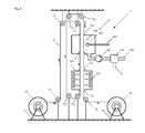
- Fig. 1 shows a sectional view of a coating device 1 according to the invention, by means of which an electrical line 10 can be coated with polymer particles 9.
- the electric wire 10 is unrolled by a unwinding unit 12, which is rotatably supported by a stand 11. Via deflection rollers 13, 14, 15, 18, the electrical line 10 is led to a coating unit 16 and vertically therethrough.
- the electrical line 10 enters through an inlet opening 161 into the coating unit 16, which is shown open, and out of this through an outlet opening 169.
- the inlet opening 161 and the outlet opening 169 are designed such that as little powder as possible can escape from the coating unit 16 without the electrical line 10 touching the edge of the outlet opening 169, for example because of vibrations or oscillations, so that abrasion does not yet occur solidified line coating can be avoided.
- the coating unit 16 contains at least one powder spray head 162 which produces a powder cloud 163 in the coating unit 16 and which is supplied with powder particles 9 via a powder line 164.
- the coating unit 16 also comprises components for the recovery of excess powder 9.
- a pump 167 is connected to the main chamber of the coating unit 16 via a recovery suction funnel 168. By the pump 167, an air flow or gas flow can be generated in the coating unit 16, so that the excess powder particles 9 are directed in the direction of the recovery suction funnel 168.
- a powder separation 165 is connected, which allows the deposition of the sucked powder particles 9 eleven.
- the powder separation 165 comprises at least exits for the exhaust air 8 and for a powder recovery line 166.
- the electrical line 10 enters through the inlet opening 171 vertically into a heating device 17, in which a heating zone is provided. Due to the advantageous arrangement of the heating device 17 immediately below the coating device 16, a deflection and thus a contact of the not yet solidified coating of the electrical line 10 is avoided, which held between the pulleys 15 and 18 vertically and in this orientation by the coating unit 16 and the heater 17 is led.
- the heating device 17 comprises a heating element 172 which can use any heating principle known from the prior art.
- the electrical line 10 After passing through the heating zone, the electrical line 10 exits the heating device 17 through an outlet opening 173. About the guide roller 18, the coated electrical line 10 is supplied to a take-up unit 19, is rotatably supported by a stator 20.
- Fig. 2a shows a cross section of the electric wire 10 of Fig. 1 after passing through the coating unit 1. On the electric line 10 not solidified powder particles 9 are attached. The dashed line shows the circumference of the resulting after solidification cable sheath 91st
- Fig. 2b shows a cross section of the electric wire 10 of Fig. 1 after passing through the heating device 17 with the solidified cable sheath 91, which is symmetrical and over the entire circumference has the same radial wall thickness MD.
- Fig. 2c shows a cross section of a not manufactured according to the inventive method line 10, after the powder coating has an asymmetric cable sheath 92.
- the not yet solidified polymer layer was pulled by the gravitational force on one side down.
- the wall thickness of the cable sheath varies between the smallest wall thickness D1 on the top of the electrical line 10 and the largest wall thickness thickness D2 on the underside of the electrical line 10.
- the material which is displaced by the gravitational force is to be compensated.
- additional material is required, which in addition leads to an increase in the weight of the manufactured conduit 10.
- conduit within the coating zone must be routed over an additional distance within which the additional required material is applied. Cables according to the invention therefore have a lower weight and a lower volume with equivalent quality and can be manufactured at lower costs. At the same time, the production takes place more efficiently and with reduced dimensions of the coating device 1.
- Fig. 3 shows the coating device 1 of Fig. 1 in a preferred embodiment with additional optional functional units.
- the electrical line 10 After unwinding from the unwinding unit 12, the electrical line 10 passes through a pre-treatment unit 21, which can be passed through horizontally or vertically. With regard to the compact construction of the entire coating apparatus 1, however, the optional functional units are also vertically aligned.
- the electrical line 10 is prepared for the efficient and high-quality coating with polymer particles 9.
- a mechanical and / or chemical cleaning of the electrical line 10 and / or the spraying with a chemical substance is provided which increases the adhesion of the polymer particles 9 to the cleaned electrical line 10.
- the electrical conduit 10 Before the electrical conduit 10 reaches the coating zone 16, it is preferably heated in a preheating zone 22, which may be passed horizontally or vertically.
- a preheating zone 22 By heating the electric wire 10, within the coating unit 16, the polymer particles 9 are caused to be partially heated or melted on being attached to the electric wire 10, thereby improving the adhesion.
- the electrical line 10 enters through an inlet opening 221 in the preheating zone 22 and through an outlet opening 223 back out of this.
- the preheating zone 22 includes a heating element 222 which may be based on any heating technique.
- the heating of the electric wire 10 can be achieved by induction, by heat radiation or convection, for which corresponding heating elements 222, e.g. electrical resistances are used.
- the coating unit 16 additionally comprises a powder reservoir 26, which is connected to the powder recovery line 166.
- the powder reservoir 26 can also be supplied with powder automatically by other sources.
- the powder reservoir 26 is connected via a delivery line 261 to a fluidization unit 27.
- Polymer particles 9 pass through the delivery line 261 to the fluidization unit 27, in which the polymer particles 9 are processed with air, a liquid, or a carrier gas to form a mixture which can be sprayed with a conventional powder spray head 162.
- the mixture is transported via a powder line 164 from the fluidization unit 27 to the powder spray head 162.
- a heating element 176 is provided within the coating unit 16, by means of which the reheated mixture and the polymer particles 9 can be heated so that For example, liquid portions of the mixture evaporates and the polymer particles 9 are heated. In this way, the optimum spraying and adhesion of the polymer particles 9 succeeds. In particular, a homogeneous powder cloud 163 is achieved.
- a suction and filter device 23 is also provided, which comprises a passage opening 231 for the electrical line 10, at least one suction hopper 232 and at least one pump 233.
- Task of the suction and filter device 23 is the suction and filtration of emerging from the coating unit 16 polymer particles 9, whereby an entry of polymer particles 9 is prevented in the heater 17.
- the electrical line 10 passes through the heater 17 and passes through the deflection roller 18 to a cooling unit 24, which can be traversed horizontally or vertically.
- the cooling unit 24 may also be connected directly to the heating device 17 and aligned vertically in front of the deflection roller 18.
- the cooling can optionally be carried out by cooling principles known from the prior art.
- the electrical line 10 is sprayed with one or more water jets and / or blown with air and / or a gas.
- the coated electric wire 10 passes through a cross-linking unit 25, in which the polymer material of the finished cable sheath 91 is cross-linked.
- the crosslinking is preferably carried out by irradiation with electrons and / or X-rays or by other methods known from the prior art.
- the line 10 is finally rolled up on the take-up unit 19.
- Fig. 4a shows the preferably configured coating unit 16 of the coating device 1 of Fig. 1 in a sectional view.
- the coating unit 16 has the shape of a pipe or a shaft 160.
- the electrical line 10 enters the coating unit 16 through an inlet opening 161 and out again through an outlet opening 169.
- the section through the coating unit 16 passes exactly through the inlet opening 161 and through the outlet opening 169.
- the coating tube 160 passes in the lower part at an angle of approximately 90 ° directly into the recovery suction 168 and tapers.
- a controllable air flow is generated in the interior of the coating tube 160, which drives the polymer particles 9 emitted by at least one powder spray head 162 through the coating tube 160 at the same speed as the electrical conduit 10 through the coating tube 160 to be led.
- the powder spray head 162 is supplied with polymer particles 9 or the described mixture with polymer particles 9 through the powder line 164.
- a first electrical potential P1 is applied to the electrical line 10 via the deflection roller 15.
- a second electrical potential P2 is applied, which is transferred to the polymer particles 9.
- a third electric potential P3 is applied, which drives the polymer particles 9 radially inward.
- the powder spray head 162 and / or the powder line 164 are electrically insulated from the coating tube 160.
- the potentials P1, P2 and P3 are selected such that the polymer particles 9 are maximally accelerated against the electrical line 10 and concentrate in the region of the center axis of the coating tube 160, whereby an optimal effect can be achieved with minimal use of polymer practical. Due to the high efficiency results in a low material requirement. At the same time, the unwanted deposition of polymer material on device objects is largely avoided.
- Fig. 4b shows a section through the coating unit 16 along the in Fig. 4a drawn section line A - A.
- the powder spray head 162 is arranged eccentrically on the coating tube 160, whereby a directed movement of the powder cloud 163 is achieved in the interior of the coating tube 160, which illustrates the dotted arrow.
- the polymer particles 9 are thus guided helically around the electrical line and coupled even more closely to the electrical line 10.
- the tubular design of the coating unit 16 also allows a compact design.
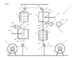
- Fig. 5 shows the coating device 1 of Fig. 1 in a further preferred embodiment with a plurality of deflection devices 14, 15 1 , 15 2 , 15 3 , 15 4 , 15 5 , 18, by means of which the electrical line 10 is repeatedly guided vertically through the same coating unit 16 therethrough.
- the electrical line 10 is again passed through these two units 16, 17 after a first vertical pass through the coating unit 16 and the heater 17.
- the electrical line 10 as desired by further deflection rollers through the Coating zone 16 and the heater 17 are performed.
- Fig. 6 shows a further preferred embodiment of the coating device 1 of Fig. 1 which has been equipped with an additional coating unit 16 'and an additional heating device 17'.
- the second coating unit 16 ' is constructed analogously to the first coating unit 16.
- the second heating device 17 ' is constructed analogously to the first heating device 17.
- the number of sequentially arranged coating units is not limited according to the invention.
- Fig. 6 shows that the coating unit 16 or 16 'both spatially below and above the subsequent heating device 17 or 17' can be arranged.
- the vertical pass remains the same.
- FIG. 1 . Fig. 3 . Fig. 5 and Fig. 6 shown embodiments of the inventive coating device 1 can optionally be combined.
- the optional functional units can optionally be added.
Landscapes
- Engineering & Computer Science (AREA)
- Manufacturing & Machinery (AREA)
- Electrostatic Spraying Apparatus (AREA)
- Application Of Or Painting With Fluid Materials (AREA)
Priority Applications (1)
| Application Number | Priority Date | Filing Date | Title |
|---|---|---|---|
| EP14153573.2A EP2902113B1 (fr) | 2014-02-02 | 2014-02-02 | Procédé et dispositif d'isolation de lignes électriques |
Applications Claiming Priority (1)
| Application Number | Priority Date | Filing Date | Title |
|---|---|---|---|
| EP14153573.2A EP2902113B1 (fr) | 2014-02-02 | 2014-02-02 | Procédé et dispositif d'isolation de lignes électriques |
Publications (2)
| Publication Number | Publication Date |
|---|---|
| EP2902113A1 true EP2902113A1 (fr) | 2015-08-05 |
| EP2902113B1 EP2902113B1 (fr) | 2019-05-22 |
Family
ID=50070334
Family Applications (1)
| Application Number | Title | Priority Date | Filing Date |
|---|---|---|---|
| EP14153573.2A Active EP2902113B1 (fr) | 2014-02-02 | 2014-02-02 | Procédé et dispositif d'isolation de lignes électriques |
Country Status (1)
| Country | Link |
|---|---|
| EP (1) | EP2902113B1 (fr) |
Cited By (6)
| Publication number | Priority date | Publication date | Assignee | Title |
|---|---|---|---|---|
| CN111054564A (zh) * | 2019-12-14 | 2020-04-24 | 重庆材料研究院有限公司 | 一种线材表面喷涂装置 |
| CN112191429A (zh) * | 2020-10-12 | 2021-01-08 | 衡阳凌云特种材料有限公司 | 一种用于高强度化纤绝缘绳生产的绝缘漆涂装处理装置 |
| CN114534978A (zh) * | 2022-03-01 | 2022-05-27 | 湖北楚天电缆实业有限公司 | 一种防水光缆的缆芯处理设备及加工方法 |
| CN114798233A (zh) * | 2022-05-05 | 2022-07-29 | 湖北楚天电缆实业有限公司 | 一种耐腐蚀性光缆的生产装置及生产方法 |
| CN116487123A (zh) * | 2023-05-18 | 2023-07-25 | 湖南盛世电线电缆有限公司 | 一种电缆生产用稳定性较高的包覆装置 |
| DE102023204012A1 (de) * | 2023-05-02 | 2024-11-07 | Volkswagen Aktiengesellschaft | Beschichtungsvorrichtung zum Beschichten eines Drahts |
Citations (6)
| Publication number | Priority date | Publication date | Assignee | Title |
|---|---|---|---|---|
| US3589332A (en) * | 1968-07-18 | 1971-06-29 | Bernhard Dinse | Apparatus for insulating thin electric conductors, particularly extremely thin copper conductors, with thermoplastic synthetic materials |
| US3616983A (en) * | 1967-12-27 | 1971-11-02 | Matsushita Electric Works Ltd | Apparatus for continuously forming plastic-coated metallic tubings |
| US4104416A (en) * | 1976-02-05 | 1978-08-01 | Canada Wire And Cable Limited | Thin walled protective coatings by electrostatic powder deposition |
| US5310582A (en) * | 1993-02-19 | 1994-05-10 | Board Of Trustees Operating Michigan State University | Apparatus and high speed method for coating elongated fibers |
| DE102006002192A1 (de) | 2006-01-16 | 2007-07-19 | Trithor Gmbh | Verfahren zur elektrischen Isolierung eines supraleitfähigen Leiters sowie mit diesem hergestellte Leiter |
| EP1990808A2 (fr) | 2007-05-07 | 2008-11-12 | JJI Technologies, LLC | Fil et câble ignifuges |
-
2014
- 2014-02-02 EP EP14153573.2A patent/EP2902113B1/fr active Active
Patent Citations (6)
| Publication number | Priority date | Publication date | Assignee | Title |
|---|---|---|---|---|
| US3616983A (en) * | 1967-12-27 | 1971-11-02 | Matsushita Electric Works Ltd | Apparatus for continuously forming plastic-coated metallic tubings |
| US3589332A (en) * | 1968-07-18 | 1971-06-29 | Bernhard Dinse | Apparatus for insulating thin electric conductors, particularly extremely thin copper conductors, with thermoplastic synthetic materials |
| US4104416A (en) * | 1976-02-05 | 1978-08-01 | Canada Wire And Cable Limited | Thin walled protective coatings by electrostatic powder deposition |
| US5310582A (en) * | 1993-02-19 | 1994-05-10 | Board Of Trustees Operating Michigan State University | Apparatus and high speed method for coating elongated fibers |
| DE102006002192A1 (de) | 2006-01-16 | 2007-07-19 | Trithor Gmbh | Verfahren zur elektrischen Isolierung eines supraleitfähigen Leiters sowie mit diesem hergestellte Leiter |
| EP1990808A2 (fr) | 2007-05-07 | 2008-11-12 | JJI Technologies, LLC | Fil et câble ignifuges |
Cited By (10)
| Publication number | Priority date | Publication date | Assignee | Title |
|---|---|---|---|---|
| CN111054564A (zh) * | 2019-12-14 | 2020-04-24 | 重庆材料研究院有限公司 | 一种线材表面喷涂装置 |
| CN112191429A (zh) * | 2020-10-12 | 2021-01-08 | 衡阳凌云特种材料有限公司 | 一种用于高强度化纤绝缘绳生产的绝缘漆涂装处理装置 |
| CN114534978A (zh) * | 2022-03-01 | 2022-05-27 | 湖北楚天电缆实业有限公司 | 一种防水光缆的缆芯处理设备及加工方法 |
| CN114534978B (zh) * | 2022-03-01 | 2023-06-16 | 湖北楚天电缆实业有限公司 | 一种防水光缆的缆芯处理设备及加工方法 |
| CN114798233A (zh) * | 2022-05-05 | 2022-07-29 | 湖北楚天电缆实业有限公司 | 一种耐腐蚀性光缆的生产装置及生产方法 |
| CN114798233B (zh) * | 2022-05-05 | 2023-06-23 | 湖北楚天电缆实业有限公司 | 一种耐腐蚀性光缆的生产装置及生产方法 |
| DE102023204012A1 (de) * | 2023-05-02 | 2024-11-07 | Volkswagen Aktiengesellschaft | Beschichtungsvorrichtung zum Beschichten eines Drahts |
| DE102023204012B4 (de) * | 2023-05-02 | 2025-10-09 | Volkswagen Aktiengesellschaft | Beschichtungsvorrichtung zum Beschichten eines Drahts |
| CN116487123A (zh) * | 2023-05-18 | 2023-07-25 | 湖南盛世电线电缆有限公司 | 一种电缆生产用稳定性较高的包覆装置 |
| CN116487123B (zh) * | 2023-05-18 | 2023-12-05 | 湖南盛世电线电缆有限公司 | 一种电缆生产用稳定性较高的包覆装置 |
Also Published As
| Publication number | Publication date |
|---|---|
| EP2902113B1 (fr) | 2019-05-22 |
Similar Documents
| Publication | Publication Date | Title |
|---|---|---|
| EP2902113B1 (fr) | Procédé et dispositif d'isolation de lignes électriques | |
| DE69528836T2 (de) | Vorrichtung und verfahren zur herstellung von gleichen dünnen beschichtungen auf breiten substraten | |
| DE69130904T2 (de) | Teilchen-strahl-generator | |
| DE2144872B2 (de) | Plasmaspritzvorrichtung | |
| DE2059594A1 (de) | Verfahren und Vorrichtung zum elektrostatischen Aufstreuen von Farbstoffen,Pulvermaterial,Faserstoffen u.dgl. | |
| EP0023238B1 (fr) | Procédé et dispositif de fabrication de fils à bobiner isolés par un vernis, en particulier fils épais | |
| DE4010306A1 (de) | Verfahren und vorrichtung zur herstellung von lackdraehten mit schmelzharzen | |
| DE2139762B2 (de) | Vorrichtung zum Überziehen eines Gegenstandes mit Pulverteilchen | |
| EP3374542B1 (fr) | Dispositif d'application d'un revêtement | |
| DE102012108919A1 (de) | Vorrichtung und Verfahren zur Erzeugung eines Schichtsystems | |
| EP1872637B1 (fr) | Dispositif et procede de revetement par jet de plasma | |
| EP1513625B1 (fr) | Procede et dispositif de traitement de la surface exterieure d'un fil metallique, notamment en tant que pretraitement de revetement | |
| EP2497334B1 (fr) | Dispositif de chauffage par induction de pièces avec refroidissement | |
| WO2004101164A1 (fr) | Procede de revetement, buse de pulverisation et cabine de revetement | |
| DE19960211B4 (de) | Vorrichtung zum Herstellen eines Glasstranges | |
| DE102023204012B4 (de) | Beschichtungsvorrichtung zum Beschichten eines Drahts | |
| DE102010033290A1 (de) | Verfahren und Vorrichtung zum Aufbringen einer Beschichtung | |
| WO2013131508A1 (fr) | Dispositif et procédé de revêtement par plasma d'éléments structuraux cylindriques de forme allongée | |
| EP2638974B1 (fr) | Utilisation d'un pulvérisateur rotatif | |
| EP4635635A1 (fr) | Dispositif de revêtement pour appliquer un matériau de revêtement sur un fil, et dispositif et procédé de fabrication de fils revêtus | |
| DE4341157A1 (de) | Abgabe- und Aufladungssystem für Beschichtungsmaterial | |
| DE102015201523A1 (de) | Verfahren und Vorrichtung zur Innenbehandlung, insbesondere zur Innenbeschichtung eines Rohres | |
| DE2749400A1 (de) | Spritzeinrichtung mit schutzgasummantelung und elektrostatischen aufladungseinrichtungen | |
| EP4736583A1 (fr) | Procédé et dispositif de revêtement d'une surface de pièce à usiner | |
| EP3228389B1 (fr) | Procédé de formation d'une barre structurale tridimensionnelle |
Legal Events
| Date | Code | Title | Description |
|---|---|---|---|
| PUAI | Public reference made under article 153(3) epc to a published international application that has entered the european phase |
Free format text: ORIGINAL CODE: 0009012 |
|
| 17P | Request for examination filed |
Effective date: 20140202 |
|
| AK | Designated contracting states |
Kind code of ref document: A1 Designated state(s): AL AT BE BG CH CY CZ DE DK EE ES FI FR GB GR HR HU IE IS IT LI LT LU LV MC MK MT NL NO PL PT RO RS SE SI SK SM TR |
|
| AX | Request for extension of the european patent |
Extension state: BA ME |
|
| 17P | Request for examination filed |
Effective date: 20160205 |
|
| RBV | Designated contracting states (corrected) |
Designated state(s): AL AT BE BG CH CY CZ DE DK EE ES FI FR GB GR HR HU IE IS IT LI LT LU LV MC MK MT NL NO PL PT RO RS SE SI SK SM TR |
|
| STAA | Information on the status of an ep patent application or granted ep patent |
Free format text: STATUS: EXAMINATION IS IN PROGRESS |
|
| 17Q | First examination report despatched |
Effective date: 20180703 |
|
| GRAP | Despatch of communication of intention to grant a patent |
Free format text: ORIGINAL CODE: EPIDOSNIGR1 |
|
| STAA | Information on the status of an ep patent application or granted ep patent |
Free format text: STATUS: GRANT OF PATENT IS INTENDED |
|
| RIC1 | Information provided on ipc code assigned before grant |
Ipc: H01B 13/16 20060101ALI20190128BHEP Ipc: B05D 7/20 20060101ALN20190128BHEP Ipc: B05D 1/12 20060101ALN20190128BHEP Ipc: B05B 14/48 20180101ALI20190128BHEP Ipc: B05D 3/02 20060101ALN20190128BHEP Ipc: B05B 5/14 20060101AFI20190128BHEP Ipc: B05B 5/08 20060101ALI20190128BHEP |
|
| INTG | Intention to grant announced |
Effective date: 20190215 |
|
| GRAS | Grant fee paid |
Free format text: ORIGINAL CODE: EPIDOSNIGR3 |
|
| GRAA | (expected) grant |
Free format text: ORIGINAL CODE: 0009210 |
|
| STAA | Information on the status of an ep patent application or granted ep patent |
Free format text: STATUS: THE PATENT HAS BEEN GRANTED |
|
| AK | Designated contracting states |
Kind code of ref document: B1 Designated state(s): AL AT BE BG CH CY CZ DE DK EE ES FI FR GB GR HR HU IE IS IT LI LT LU LV MC MK MT NL NO PL PT RO RS SE SI SK SM TR |
|
| REG | Reference to a national code |
Ref country code: GB Ref legal event code: FG4D Free format text: NOT ENGLISH |
|
| REG | Reference to a national code |
Ref country code: CH Ref legal event code: EP |
|
| REG | Reference to a national code |
Ref country code: IE Ref legal event code: FG4D Free format text: LANGUAGE OF EP DOCUMENT: GERMAN |
|
| REG | Reference to a national code |
Ref country code: DE Ref legal event code: R096 Ref document number: 502014011744 Country of ref document: DE |
|
| REG | Reference to a national code |
Ref country code: AT Ref legal event code: REF Ref document number: 1135458 Country of ref document: AT Kind code of ref document: T Effective date: 20190615 |
|
| REG | Reference to a national code |
Ref country code: NL Ref legal event code: MP Effective date: 20190522 |
|
| REG | Reference to a national code |
Ref country code: LT Ref legal event code: MG4D |
|
| PG25 | Lapsed in a contracting state [announced via postgrant information from national office to epo] |
Ref country code: NO Free format text: LAPSE BECAUSE OF FAILURE TO SUBMIT A TRANSLATION OF THE DESCRIPTION OR TO PAY THE FEE WITHIN THE PRESCRIBED TIME-LIMIT Effective date: 20190822 Ref country code: FI Free format text: LAPSE BECAUSE OF FAILURE TO SUBMIT A TRANSLATION OF THE DESCRIPTION OR TO PAY THE FEE WITHIN THE PRESCRIBED TIME-LIMIT Effective date: 20190522 Ref country code: PT Free format text: LAPSE BECAUSE OF FAILURE TO SUBMIT A TRANSLATION OF THE DESCRIPTION OR TO PAY THE FEE WITHIN THE PRESCRIBED TIME-LIMIT Effective date: 20190922 Ref country code: ES Free format text: LAPSE BECAUSE OF FAILURE TO SUBMIT A TRANSLATION OF THE DESCRIPTION OR TO PAY THE FEE WITHIN THE PRESCRIBED TIME-LIMIT Effective date: 20190522 Ref country code: AL Free format text: LAPSE BECAUSE OF FAILURE TO SUBMIT A TRANSLATION OF THE DESCRIPTION OR TO PAY THE FEE WITHIN THE PRESCRIBED TIME-LIMIT Effective date: 20190522 Ref country code: SE Free format text: LAPSE BECAUSE OF FAILURE TO SUBMIT A TRANSLATION OF THE DESCRIPTION OR TO PAY THE FEE WITHIN THE PRESCRIBED TIME-LIMIT Effective date: 20190522 Ref country code: LT Free format text: LAPSE BECAUSE OF FAILURE TO SUBMIT A TRANSLATION OF THE DESCRIPTION OR TO PAY THE FEE WITHIN THE PRESCRIBED TIME-LIMIT Effective date: 20190522 Ref country code: NL Free format text: LAPSE BECAUSE OF FAILURE TO SUBMIT A TRANSLATION OF THE DESCRIPTION OR TO PAY THE FEE WITHIN THE PRESCRIBED TIME-LIMIT Effective date: 20190522 Ref country code: HR Free format text: LAPSE BECAUSE OF FAILURE TO SUBMIT A TRANSLATION OF THE DESCRIPTION OR TO PAY THE FEE WITHIN THE PRESCRIBED TIME-LIMIT Effective date: 20190522 |
|
| PG25 | Lapsed in a contracting state [announced via postgrant information from national office to epo] |
Ref country code: RS Free format text: LAPSE BECAUSE OF FAILURE TO SUBMIT A TRANSLATION OF THE DESCRIPTION OR TO PAY THE FEE WITHIN THE PRESCRIBED TIME-LIMIT Effective date: 20190522 Ref country code: BG Free format text: LAPSE BECAUSE OF FAILURE TO SUBMIT A TRANSLATION OF THE DESCRIPTION OR TO PAY THE FEE WITHIN THE PRESCRIBED TIME-LIMIT Effective date: 20190822 Ref country code: GR Free format text: LAPSE BECAUSE OF FAILURE TO SUBMIT A TRANSLATION OF THE DESCRIPTION OR TO PAY THE FEE WITHIN THE PRESCRIBED TIME-LIMIT Effective date: 20190823 Ref country code: LV Free format text: LAPSE BECAUSE OF FAILURE TO SUBMIT A TRANSLATION OF THE DESCRIPTION OR TO PAY THE FEE WITHIN THE PRESCRIBED TIME-LIMIT Effective date: 20190522 |
|
| PG25 | Lapsed in a contracting state [announced via postgrant information from national office to epo] |
Ref country code: SK Free format text: LAPSE BECAUSE OF FAILURE TO SUBMIT A TRANSLATION OF THE DESCRIPTION OR TO PAY THE FEE WITHIN THE PRESCRIBED TIME-LIMIT Effective date: 20190522 Ref country code: RO Free format text: LAPSE BECAUSE OF FAILURE TO SUBMIT A TRANSLATION OF THE DESCRIPTION OR TO PAY THE FEE WITHIN THE PRESCRIBED TIME-LIMIT Effective date: 20190522 Ref country code: CZ Free format text: LAPSE BECAUSE OF FAILURE TO SUBMIT A TRANSLATION OF THE DESCRIPTION OR TO PAY THE FEE WITHIN THE PRESCRIBED TIME-LIMIT Effective date: 20190522 Ref country code: EE Free format text: LAPSE BECAUSE OF FAILURE TO SUBMIT A TRANSLATION OF THE DESCRIPTION OR TO PAY THE FEE WITHIN THE PRESCRIBED TIME-LIMIT Effective date: 20190522 Ref country code: DK Free format text: LAPSE BECAUSE OF FAILURE TO SUBMIT A TRANSLATION OF THE DESCRIPTION OR TO PAY THE FEE WITHIN THE PRESCRIBED TIME-LIMIT Effective date: 20190522 |
|
| REG | Reference to a national code |
Ref country code: DE Ref legal event code: R097 Ref document number: 502014011744 Country of ref document: DE |
|
| PG25 | Lapsed in a contracting state [announced via postgrant information from national office to epo] |
Ref country code: SM Free format text: LAPSE BECAUSE OF FAILURE TO SUBMIT A TRANSLATION OF THE DESCRIPTION OR TO PAY THE FEE WITHIN THE PRESCRIBED TIME-LIMIT Effective date: 20190522 Ref country code: IT Free format text: LAPSE BECAUSE OF FAILURE TO SUBMIT A TRANSLATION OF THE DESCRIPTION OR TO PAY THE FEE WITHIN THE PRESCRIBED TIME-LIMIT Effective date: 20190522 |
|
| PLBE | No opposition filed within time limit |
Free format text: ORIGINAL CODE: 0009261 |
|
| STAA | Information on the status of an ep patent application or granted ep patent |
Free format text: STATUS: NO OPPOSITION FILED WITHIN TIME LIMIT |
|
| PG25 | Lapsed in a contracting state [announced via postgrant information from national office to epo] |
Ref country code: TR Free format text: LAPSE BECAUSE OF FAILURE TO SUBMIT A TRANSLATION OF THE DESCRIPTION OR TO PAY THE FEE WITHIN THE PRESCRIBED TIME-LIMIT Effective date: 20190522 |
|
| 26N | No opposition filed |
Effective date: 20200225 |
|
| PG25 | Lapsed in a contracting state [announced via postgrant information from national office to epo] |
Ref country code: PL Free format text: LAPSE BECAUSE OF FAILURE TO SUBMIT A TRANSLATION OF THE DESCRIPTION OR TO PAY THE FEE WITHIN THE PRESCRIBED TIME-LIMIT Effective date: 20190522 |
|
| PG25 | Lapsed in a contracting state [announced via postgrant information from national office to epo] |
Ref country code: SI Free format text: LAPSE BECAUSE OF FAILURE TO SUBMIT A TRANSLATION OF THE DESCRIPTION OR TO PAY THE FEE WITHIN THE PRESCRIBED TIME-LIMIT Effective date: 20190522 |
|
| REG | Reference to a national code |
Ref country code: BE Ref legal event code: MM Effective date: 20200229 |
|
| PG25 | Lapsed in a contracting state [announced via postgrant information from national office to epo] |
Ref country code: LU Free format text: LAPSE BECAUSE OF NON-PAYMENT OF DUE FEES Effective date: 20200202 Ref country code: MC Free format text: LAPSE BECAUSE OF FAILURE TO SUBMIT A TRANSLATION OF THE DESCRIPTION OR TO PAY THE FEE WITHIN THE PRESCRIBED TIME-LIMIT Effective date: 20190522 |
|
| PG25 | Lapsed in a contracting state [announced via postgrant information from national office to epo] |
Ref country code: IE Free format text: LAPSE BECAUSE OF NON-PAYMENT OF DUE FEES Effective date: 20200202 |
|
| PG25 | Lapsed in a contracting state [announced via postgrant information from national office to epo] |
Ref country code: BE Free format text: LAPSE BECAUSE OF NON-PAYMENT OF DUE FEES Effective date: 20200229 |
|
| PG25 | Lapsed in a contracting state [announced via postgrant information from national office to epo] |
Ref country code: MT Free format text: LAPSE BECAUSE OF FAILURE TO SUBMIT A TRANSLATION OF THE DESCRIPTION OR TO PAY THE FEE WITHIN THE PRESCRIBED TIME-LIMIT Effective date: 20190522 Ref country code: CY Free format text: LAPSE BECAUSE OF FAILURE TO SUBMIT A TRANSLATION OF THE DESCRIPTION OR TO PAY THE FEE WITHIN THE PRESCRIBED TIME-LIMIT Effective date: 20190522 |
|
| PG25 | Lapsed in a contracting state [announced via postgrant information from national office to epo] |
Ref country code: MK Free format text: LAPSE BECAUSE OF FAILURE TO SUBMIT A TRANSLATION OF THE DESCRIPTION OR TO PAY THE FEE WITHIN THE PRESCRIBED TIME-LIMIT Effective date: 20190522 Ref country code: IS Free format text: LAPSE BECAUSE OF FAILURE TO SUBMIT A TRANSLATION OF THE DESCRIPTION OR TO PAY THE FEE WITHIN THE PRESCRIBED TIME-LIMIT Effective date: 20190922 |
|
| P01 | Opt-out of the competence of the unified patent court (upc) registered |
Effective date: 20230529 |
|
| REG | Reference to a national code |
Ref country code: CH Ref legal event code: U11 Free format text: ST27 STATUS EVENT CODE: U-0-0-U10-U11 (AS PROVIDED BY THE NATIONAL OFFICE) Effective date: 20260301 |
|
| PGFP | Annual fee paid to national office [announced via postgrant information from national office to epo] |
Ref country code: GB Payment date: 20260219 Year of fee payment: 13 |
|
| PGFP | Annual fee paid to national office [announced via postgrant information from national office to epo] |
Ref country code: DE Payment date: 20260218 Year of fee payment: 13 |
|
| PGFP | Annual fee paid to national office [announced via postgrant information from national office to epo] |
Ref country code: AT Payment date: 20260219 Year of fee payment: 13 |
|
| PGFP | Annual fee paid to national office [announced via postgrant information from national office to epo] |
Ref country code: FR Payment date: 20260218 Year of fee payment: 13 |
|
| PGFP | Annual fee paid to national office [announced via postgrant information from national office to epo] |
Ref country code: CH Payment date: 20260301 Year of fee payment: 13 |