EP2903077A1 - Élément de conversion photoélectrique et cellule solaire à colorant - Google Patents
Élément de conversion photoélectrique et cellule solaire à colorant Download PDFInfo
- Publication number
- EP2903077A1 EP2903077A1 EP13842001.3A EP13842001A EP2903077A1 EP 2903077 A1 EP2903077 A1 EP 2903077A1 EP 13842001 A EP13842001 A EP 13842001A EP 2903077 A1 EP2903077 A1 EP 2903077A1
- Authority
- EP
- European Patent Office
- Prior art keywords
- ring
- group
- coordinated
- carbon atom
- photoelectric conversion
- Prior art date
- Legal status (The legal status is an assumption and is not a legal conclusion. Google has not performed a legal analysis and makes no representation as to the accuracy of the status listed.)
- Withdrawn
Links
- 0 *c1cc(C(SC(*2)I)=CC2C(C2)*22C=C2)ccc1 Chemical compound *c1cc(C(SC(*2)I)=CC2C(C2)*22C=C2)ccc1 0.000 description 44
- MDZDEBKCEOKKHL-UHFFFAOYSA-N C(C1)C=Cc2c1cc[nH]2 Chemical compound C(C1)C=Cc2c1cc[nH]2 MDZDEBKCEOKKHL-UHFFFAOYSA-N 0.000 description 1
- JAYCUVNLGQLPJE-QVFDXSDSSA-N C/C(/C(/N=C(\C)/c1ccccn1)=C/C=C)=N\CC=C Chemical compound C/C(/C(/N=C(\C)/c1ccccn1)=C/C=C)=N\CC=C JAYCUVNLGQLPJE-QVFDXSDSSA-N 0.000 description 1
- OPLCJEHZDGETGZ-ONEGZZNKSA-N C/C=C/c1ccc(C)[s]1 Chemical compound C/C=C/c1ccc(C)[s]1 OPLCJEHZDGETGZ-ONEGZZNKSA-N 0.000 description 1
- UZQYHIKFRSGLAK-UHFFFAOYSA-O CC(C1)[NH+](C)CCC(C)=C1C(F)(F)F Chemical compound CC(C1)[NH+](C)CCC(C)=C1C(F)(F)F UZQYHIKFRSGLAK-UHFFFAOYSA-O 0.000 description 1
- PEALNNNOMYJKBZ-UHFFFAOYSA-N CC(CC(N)I)=N Chemical compound CC(CC(N)I)=N PEALNNNOMYJKBZ-UHFFFAOYSA-N 0.000 description 1
- AQVFBUSGSGXGNX-UHFFFAOYSA-N CC1=CC(C(F)(F)F)=N[NH+]1[O-] Chemical compound CC1=CC(C(F)(F)F)=N[NH+]1[O-] AQVFBUSGSGXGNX-UHFFFAOYSA-N 0.000 description 1
- JACYLCFJAUIORU-UHFFFAOYSA-N CC1=CC(CCCCF)=N[N+]1(C)[O-] Chemical compound CC1=CC(CCCCF)=N[N+]1(C)[O-] JACYLCFJAUIORU-UHFFFAOYSA-N 0.000 description 1
- SMOJLMIGQFAGGY-UHFFFAOYSA-N CC1=NNC2C1C2 Chemical compound CC1=NNC2C1C2 SMOJLMIGQFAGGY-UHFFFAOYSA-N 0.000 description 1
- AELOPASXFUVIIK-UHFFFAOYSA-N CC1NC(C(C)=O)=CC=C1 Chemical compound CC1NC(C(C)=O)=CC=C1 AELOPASXFUVIIK-UHFFFAOYSA-N 0.000 description 1
- MQUARDNMPDSFQP-MFLXPROGSA-N C[C@@H](/C=C(\N)/I)N Chemical compound C[C@@H](/C=C(\N)/I)N MQUARDNMPDSFQP-MFLXPROGSA-N 0.000 description 1
- MQSLINQSJFALSP-UHFFFAOYSA-N C[n]1nc(C(F)(F)F)cc1 Chemical compound C[n]1nc(C(F)(F)F)cc1 MQSLINQSJFALSP-UHFFFAOYSA-N 0.000 description 1
- FPTUCCXFFWYEOU-UHFFFAOYSA-N Cc(ncc(Cl)c1)c1Cl Chemical compound Cc(ncc(Cl)c1)c1Cl FPTUCCXFFWYEOU-UHFFFAOYSA-N 0.000 description 1
- PQKSCGVOQVRTEH-UHFFFAOYSA-N Cc1cc(C(F)(F)F)n[o]1 Chemical compound Cc1cc(C(F)(F)F)n[o]1 PQKSCGVOQVRTEH-UHFFFAOYSA-N 0.000 description 1
- NQDANJWAJGALMV-QNLMZQHDSA-N N/C(/I)=C\C(c1ccccc1)=N Chemical compound N/C(/I)=C\C(c1ccccc1)=N NQDANJWAJGALMV-QNLMZQHDSA-N 0.000 description 1
Images
Classifications
-
- C—CHEMISTRY; METALLURGY
- C09—DYES; PAINTS; POLISHES; NATURAL RESINS; ADHESIVES; COMPOSITIONS NOT OTHERWISE PROVIDED FOR; APPLICATIONS OF MATERIALS NOT OTHERWISE PROVIDED FOR
- C09B—ORGANIC DYES OR CLOSELY-RELATED COMPOUNDS FOR PRODUCING DYES, e.g. PIGMENTS; MORDANTS; LAKES
- C09B57/00—Other synthetic dyes of known constitution
- C09B57/10—Metal complexes of organic compounds not being dyes in uncomplexed form
-
- C—CHEMISTRY; METALLURGY
- C09—DYES; PAINTS; POLISHES; NATURAL RESINS; ADHESIVES; COMPOSITIONS NOT OTHERWISE PROVIDED FOR; APPLICATIONS OF MATERIALS NOT OTHERWISE PROVIDED FOR
- C09B—ORGANIC DYES OR CLOSELY-RELATED COMPOUNDS FOR PRODUCING DYES, e.g. PIGMENTS; MORDANTS; LAKES
- C09B23/00—Methine or polymethine dyes, e.g. cyanine dyes
- C09B23/10—The polymethine chain containing an even number of >CH- groups
- C09B23/105—The polymethine chain containing an even number of >CH- groups two >CH- groups
-
- C—CHEMISTRY; METALLURGY
- C09—DYES; PAINTS; POLISHES; NATURAL RESINS; ADHESIVES; COMPOSITIONS NOT OTHERWISE PROVIDED FOR; APPLICATIONS OF MATERIALS NOT OTHERWISE PROVIDED FOR
- C09B—ORGANIC DYES OR CLOSELY-RELATED COMPOUNDS FOR PRODUCING DYES, e.g. PIGMENTS; MORDANTS; LAKES
- C09B57/00—Other synthetic dyes of known constitution
- C09B57/008—Triarylamine dyes containing no other chromophores
-
- H—ELECTRICITY
- H01—ELECTRIC ELEMENTS
- H01G—CAPACITORS; CAPACITORS, RECTIFIERS, DETECTORS, SWITCHING DEVICES, LIGHT-SENSITIVE OR TEMPERATURE-SENSITIVE DEVICES OF THE ELECTROLYTIC TYPE
- H01G9/00—Electrolytic capacitors, rectifiers, detectors, switching devices, light-sensitive or temperature-sensitive devices; Processes of their manufacture
- H01G9/20—Light-sensitive devices
- H01G9/2059—Light-sensitive devices comprising an organic dye as the active light absorbing material, e.g. adsorbed on an electrode or dissolved in solution
-
- H—ELECTRICITY
- H10—SEMICONDUCTOR DEVICES; ELECTRIC SOLID-STATE DEVICES NOT OTHERWISE PROVIDED FOR
- H10K—ORGANIC ELECTRIC SOLID-STATE DEVICES
- H10K85/00—Organic materials used in the body or electrodes of devices covered by this subclass
- H10K85/30—Coordination compounds
- H10K85/341—Transition metal complexes, e.g. Ru(II)polypyridine complexes
- H10K85/344—Transition metal complexes, e.g. Ru(II)polypyridine complexes comprising ruthenium
-
- C—CHEMISTRY; METALLURGY
- C07—ORGANIC CHEMISTRY
- C07J—STEROIDS
- C07J9/00—Normal steroids containing carbon, hydrogen, halogen or oxygen substituted in position 17 beta by a chain of more than two carbon atoms, e.g. cholane, cholestane, coprostane
- C07J9/005—Normal steroids containing carbon, hydrogen, halogen or oxygen substituted in position 17 beta by a chain of more than two carbon atoms, e.g. cholane, cholestane, coprostane containing a carboxylic function directly attached or attached by a chain containing only carbon atoms to the cyclopenta[a]hydrophenanthrene skeleton
-
- H—ELECTRICITY
- H01—ELECTRIC ELEMENTS
- H01G—CAPACITORS; CAPACITORS, RECTIFIERS, DETECTORS, SWITCHING DEVICES, LIGHT-SENSITIVE OR TEMPERATURE-SENSITIVE DEVICES OF THE ELECTROLYTIC TYPE
- H01G9/00—Electrolytic capacitors, rectifiers, detectors, switching devices, light-sensitive or temperature-sensitive devices; Processes of their manufacture
- H01G9/20—Light-sensitive devices
- H01G9/2004—Light-sensitive devices characterised by the electrolyte, e.g. comprising an organic electrolyte
- H01G9/2018—Light-sensitive devices characterised by the electrolyte, e.g. comprising an organic electrolyte characterised by the ionic charge transport species, e.g. redox shuttles
-
- H—ELECTRICITY
- H01—ELECTRIC ELEMENTS
- H01G—CAPACITORS; CAPACITORS, RECTIFIERS, DETECTORS, SWITCHING DEVICES, LIGHT-SENSITIVE OR TEMPERATURE-SENSITIVE DEVICES OF THE ELECTROLYTIC TYPE
- H01G9/00—Electrolytic capacitors, rectifiers, detectors, switching devices, light-sensitive or temperature-sensitive devices; Processes of their manufacture
- H01G9/20—Light-sensitive devices
- H01G9/2027—Light-sensitive devices comprising an oxide semiconductor electrode
- H01G9/2031—Light-sensitive devices comprising an oxide semiconductor electrode comprising titanium oxide, e.g. TiO2
-
- H—ELECTRICITY
- H10—SEMICONDUCTOR DEVICES; ELECTRIC SOLID-STATE DEVICES NOT OTHERWISE PROVIDED FOR
- H10K—ORGANIC ELECTRIC SOLID-STATE DEVICES
- H10K85/00—Organic materials used in the body or electrodes of devices covered by this subclass
- H10K85/30—Coordination compounds
- H10K85/331—Metal complexes comprising an iron-series metal, e.g. Fe, Co, Ni
-
- Y—GENERAL TAGGING OF NEW TECHNOLOGICAL DEVELOPMENTS; GENERAL TAGGING OF CROSS-SECTIONAL TECHNOLOGIES SPANNING OVER SEVERAL SECTIONS OF THE IPC; TECHNICAL SUBJECTS COVERED BY FORMER USPC CROSS-REFERENCE ART COLLECTIONS [XRACs] AND DIGESTS
- Y02—TECHNOLOGIES OR APPLICATIONS FOR MITIGATION OR ADAPTATION AGAINST CLIMATE CHANGE
- Y02E—REDUCTION OF GREENHOUSE GAS [GHG] EMISSIONS, RELATED TO ENERGY GENERATION, TRANSMISSION OR DISTRIBUTION
- Y02E10/00—Energy generation through renewable energy sources
- Y02E10/50—Photovoltaic [PV] energy
- Y02E10/542—Dye sensitized solar cells
-
- Y—GENERAL TAGGING OF NEW TECHNOLOGICAL DEVELOPMENTS; GENERAL TAGGING OF CROSS-SECTIONAL TECHNOLOGIES SPANNING OVER SEVERAL SECTIONS OF THE IPC; TECHNICAL SUBJECTS COVERED BY FORMER USPC CROSS-REFERENCE ART COLLECTIONS [XRACs] AND DIGESTS
- Y02—TECHNOLOGIES OR APPLICATIONS FOR MITIGATION OR ADAPTATION AGAINST CLIMATE CHANGE
- Y02E—REDUCTION OF GREENHOUSE GAS [GHG] EMISSIONS, RELATED TO ENERGY GENERATION, TRANSMISSION OR DISTRIBUTION
- Y02E10/00—Energy generation through renewable energy sources
- Y02E10/50—Photovoltaic [PV] energy
- Y02E10/549—Organic PV cells
Definitions
- the present invention relates to a photoelectric conversion element and a dye-sensitized solar cell.
- Photoelectric conversion elements are used in various photosensors, copy machines, solar cells, and the like.
- the photoelectric conversion elements have been put to practical use in the form of photoelectric conversion elements adopting various modes, such as photoelectric conversion element using metals, photoelectric conversion elements using semiconductors, photoelectric conversion elements using organic pigments or dyes, or photoelectric conversion elements as a combination of these.
- solar cells using inexhaustible solar energy do not require fuels and use wasteless clean energy
- full-scale commercialization of the solar cells is highly anticipated.
- silicon-based solar cells have been researched and developed for a long period of time, and are becoming increasingly popular by the political support of each country.
- silicon is an inorganic material, the improvement of throughput, cost, and the like thereof is inevitably limited.
- ruthenium metal complex dye which has excellent an absorption coefficient within a wavelength range of 450 nm to 550 nm, photoelectric conversion efficiency, and stability and contains terpyridin and 3-trifluoromethyl-5-[4-(p-substituted phenylethenyl)-2-pyridyl]pyrazol as ligands (see Chemical Communications, 2009, pp 5844-5846 ).
- JP2012-36237A describes that if a specific substituent is introduced into a nitrogen-containing ring structure constituting a ligand of a metal complex dye, photoelectric conversion efficiency of a photoelectric conversion element is improved, and durability is further improved.
- KR10-2012-0035696A describes a ruthenium dye in which a specific electron-withdrawing substituent has been introduced into a tridentate ligand having a pyridine ring structure.
- An object of the present invention is to provide a photoelectric conversion element that makes a contribution to the further improvement of photoelectric conversion efficiency ( ⁇ ) and durability of a dye-sensitized solar cell, and a dye-sensitized solar cell using the photoelectric conversion element.
- the present inventors performed intensive examination. As a result, they found that in a metal complex dye which contains a ligand having a terpyridine structure having an adsorptive group to be adsorbed onto the surface of semiconductor particles and a specific bidentate or tridentate ligand having an aryl group or an heterocyclic group, if a specific electron-withdrawing group is introduced into the ligand having a terpyridine structure as a substituent, and at least one of the coordinating atoms in the bidentate or tridentate ligand having an aryl group or an heterocyclic group is turned into an anionic atom, photoelectric conversion efficiency ( ⁇ ) and durability of a dye-sensitized solar cell are improved.
- the present invention has been completed based on these findings.
- a photoelectric conversion element including a conductive substrate, a photosensitive layer containing an electrolyte, a charge transfer layer containing an electrolyte, and a counter electrode, in which the photosensitive layer contains semiconductor particles supporting a metal complex dye represented by the following Formula (1).
- M represents a divalent or trivalent metal ion.
- LD represents a bidentate or tridentate ligand having an aryl group or an heterocyclic group, and the ligand has 1 to 3 atoms that are coordinated with M by becoming an anion.
- LA represents a tridentate ligand represented by the following Formula (2).
- X represents a monodentate ligand.
- CI represents a counter ion necessary for neutralizing a charge m represents 0 or 1.
- Ad represents either an adsorptive group selected from among -COOH, -SO 3 H, -PO 3 H 2 , -OH, -SH, and salts of these or a group having the adsorptive group.
- a represents an integer of 0 to 3, but all a do not represent 0 at the same time.
- R EWG represents an electron-withdrawing group selected from among -NO 2 , -SO 2 R, -SO 3 R, -F, -Cl, -Br, -I, -CN, -COR, and a perfluoroalkyl group.
- R represents a group selected from among an alkyl group, an aryl group, an alkenyl group, an alkynyl group, a heterocyclic group, and an amino group.
- n represents an integer of equal to or greater than 0, but all n do not represent 0 at the same time.
- * represents a coordination position in which the ligand is coordinated with M.
- a 111 , A 121 , A 131 , and A 141 represents an anionic coordinating atom that is any of a nitrogen atom or a carbon atom.
- a ring D represents an aromatic hydrocarbon ring or a heterocyclic ring.
- R 111 to R 114 , R 121 to R 123 , R 131 to R 133 , and R 141 and R 142 independently represents a hydrogen atom or a substituent.
- R B represents a substituent.
- Each of a2 and a3 independently represents an integer of equal to or greater than 0, and a4 represents an integer of 0 to 4.
- a5 represents an integer of 0 to 3.
- a6 represents an integer of 0 to 2.
- a ring A represents a ring structure selected from among a pyrimidine ring, a pyrazine ring, a pyridazine ring, a triazine ring, a pyridine ring that is coordinated with M through a carbon atom, a thiophene ring that is coordinated with M through a carbon atom, a furan ring that is coordinated with M through a carbon atom, an imidazole ring, an oxazole ring, a thiazole ring, an oxadiazole ring, a thiadiazole ring, an isoxazole ring, an isothiazole ring, a triazole ring, a pyrazole ring, a pyrrole ring, and a benzene ring.
- a ring A' represents a ring structure selected from among a pyrimidine ring that is coordinated with M through a carbon atom, a pyrazine ring that is coordinated with M through a carbon atom, a pyridazine ring that is coordinated with M through a carbon atom, a pyridine ring that is coordinated with M through a carbon atom, a thiophene ring that is coordinated with M through a carbon atom, a furan ring that is coordinated with M through a carbon atom, an imidazole ring, an oxazole ring that is coordinated with M through a carbon atom, a thiazole ring that is coordinated with M through a carbon atom, an oxadiazole ring that is coordinated with M through a carbon atom, a thiadiazole ring that is coordinated with M through a carbon atom, an isoxazole ring that is coordinated with M through a carbon atom, an isothiazole ring
- a ring B represents a ring structure selected from among a pyrimidine ring, a triazine ring, an imidazole ring, an oxazole ring, a thiazole ring, an oxadiazole ring, a thiadiazole ring, a triazole ring, a pyrazole ring, a pyrrole ring, and a benzene ring.
- a ring B' represents a ring structure selected from among a pyrimidine ring that is coordinated with M through a carbon atom, an imidazole ring, an oxazole ring that is coordinated with M through a carbon atom, a thiazole ring that is coordinated with M through a carbon atom, an oxadiazole ring that is coordinated with M through a carbon atom, a thiadiazole ring that is coordinated with M through a carbon atom, a triazole ring, a pyrazole ring, a pyrrole ring, and a benzene ring.
- a ring D' represents an aromatic hydrocarbon ring or a heterocyclic ring.
- Each of Ax and Ay independently represents a nitrogen atom, an oxygen atom, or a sulfur atom.
- at least one of Ax and Ay is an anion.
- two ring As present in Formula (3L-1) may be the same as or different from each other, and two ring D's present in Formula (3L-6) may be the same as or different from each other.
- R A1 represents a substituent having an adsorptive group.
- R A2 represents a substituent.
- nA represents an integer of equal to or greater than 0.
- the double bond when an E-isomer and a Z-isomer are present in a molecule, unless otherwise specified, the double bond may form either the E-isomer or the Z-isomer, or form a mixture thereof.
- substituents and the like when there are a plurality of substituents, linking groups, ligands, ring structures, and the like (hereinafter, referred to as "substituents and the like) marked with a specific sign, or when the plurality of substituents and the like are specified collectively or selectively, unless otherwise specified, the substituents and the like may be the same as or different from each other. The same will be applied to the case of specifying the number of the substituents and the like. Furthermore, when the plurality of substituents are close to each other (particularly, when they are adjacent to each other), unless otherwise specified, the substituents may form a ring by binding to each other.
- rings for example, an alicyclic ring, an aromatic ring, or a heterocyclic ring may form a condensed ring by being further condensed.
- the meaning of the term “ring” includes a condensed ring.
- examples of the "group having an adsorptive group” or the “substituent having an adsorptive group” include the groups described regarding Ad which will be described later.
- each of the substituents may further have a substituent.
- the photoelectric conversion element and the dye-sensitized solar cell of the present invention have an excellent photoelectric conversion efficiency ( ⁇ ) and durability.
- the metal complex dye used in the present invention is used as a photosensitive layer of a photoelectric conversion element by being supported on the surface of semiconductor particles, the photoelectric conversion efficiency ( ⁇ ) and durability of the dye-sensitized solar cell using the photoelectric conversion element can be further improved.
- the photoelectric conversion element of the present invention is formed by using semiconductor particles supporting the metal complex dye represented by Formula (1), which will be described later.
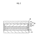
- the dye-sensitized solar cell of the present invention is formed by using the photoelectric conversion element, and includes a conductive substrate. On the conductive substrate, a photosensitive layer that contains semiconductor particles supporting the metal complex dye represented by Formula (1) which will be described later, a charge transfer layer that contains an electrolyte, and a counter electrode are disposed in this order.
- Each of the layers may be constituted with a single layer or multiple layers, and if necessary, the dye-sensitized solar cell may further include layers other than each of the aforementioned layers.
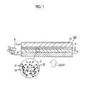
- the photoelectric conversion element and the dye-sensitized solar cell of the present invention can be in the form of the embodiment shown in Fig. 1 .
- a photoelectric conversion element 10 shown in Fig 1 includes a conductive substrate 1, a photosensitive layer 2 containing semiconductor particles that is disposed on the conductive substrate 1 and has been sensitized with a dye 21, a charge transfer layer 3, and a counter electrode 4.
- the conductive substrate 1, in which the photosensitive layer 2 is installed functions as a working electrode in the photoelectric conversion element 10.
- the photoelectric conversion element 10 is described in the form of a dye-sensitized solar cell system 100 which can be obtained when the photoelectric conversion element 10 is used as a battery that makes operating means MT work through an external circuit 6.
- a light-receiving electrode 5 is composed of the conductive substrate 1 and the photosensitive layer 2 that contains semiconductor particles 22 supporting (having adsorbed) the dye 21, and is provided on the conductive substrate 1 by coating.
- the photosensitive layer 2 is designed according to the purpose, and may be constituted with a single layer or multiple layers.
- a single photosensitive layer may contain one kind of the dye 21 or a mixture of plural kinds of the dye. However, at least one kind among the dyes used is the metal complex dye, which will be described later, used in the present invention.
- the light that has entered the photosensitive layer 2 excites the dye.
- the excited dye has electrons having high energy. The electrons are transferred to the conduction band of the semiconductor particles 22 from the dye 21 and then reach the semiconductor memory device 1 by diffusion.
- the metal complex dye has turned into an oxidized dye
- electrons on the electrode work in the external circuit 6 passes the counter electrode 4, and return to the photosensitive layer 2 in which the oxidized dye (metal complex dye) 21 and an electrolyte are present.
- the photoelectric conversion element functions as a solar cell.
- Fig. 1 is a view for schematically illustrating the embodiment of the present invention.
- the way the dye is adsorbed the constitution (single layer-multiple layers) of each layer, and the like are not limited to the constitution shown in Fig. 1 .
- the materials and methods for preparing each of the members that are generally used for photoelectric conversion elements and dye-sensitized solar cells may be adopted.
- US4927721A , US4684537A , US5084365A , US5350644A , US5463057A , US5525440A , JP1995-249790A ( JP-H07-249790A ), JP2004-220974A , and JP2008-135197A can be referred to.
- the photosensitive layer contains an electrolyte which will be described later. It is a layer containing semiconductor particles supporting a sensitizing dye including the metal complex dye used in the present invention that will be described later.
- a sensitizing dye is used for increasing photosensitivity of semiconductor particles by being supported on (adsorbed onto) the surface of the semiconductor particles.
- a metal complex dye represented by the following Formula (1) is used as the sensitizing dye.
- M is a central metal and represents a divalent or trivalent metalion.
- M is preferably a metal ion that can be coordinated with a tetradentate ligand or a hexadentate ligand.
- metal atoms of the metal ion include Ru, Fe, Os, Cu, W, Cr, Mo, Ni, Pd, Pt, Co, Ir, Rh, Re, Mn, and Zn.
- the metal ion is preferably Ru 2+ , Os 2+ , or Fe 2+ , particularly preferably Ru 2+ or Os 2+ , and most preferably Ru 2+ .
- the valency of the metal ion in a state of being incorporated into the photoelectric conversion element changes in some cases due to an oxidation-reduction reaction between M and the surrounding material.
- LA represents a tridentate ligand represented by the following Formula (2).
- Ad represents either a group (adsorptive group) that exhibits adsorptivity with respect to the surface of semiconductor particles or a group having the adsorptive group.
- the adsorptive group is selected from among -COOH, -SO 3 H -PO 3 H 2 , -OH, -SH, and salts of these.
- Ad is preferably the adsorptive group, and as Ad, -COOH or a salt thereof is suitable.
- the total number of Ad is preferably 1 to 3, and more preferably 2.
- each of two pyridine rings adjacent to each other preferably has one Ad, and the remaining pyridine ring preferably do not have Ad.
- R EWG represents an electron-withdrawing group selected from among -NO 2 , -SO 2 R, -SO 3 R, -F, -Cl, -Br, -I, -CN, -COR, and a perfluoroalkyl group.
- R represents a group selected from among an alkyl group, an aryl group, an alkenyl group, an alkynyl group, a heterocyclic group, and an amino group.
- the amino group includes an amino group, an alkylamino group, a N,N-dialkylamino group, an arylamino group, a N,N-diarylamino group, a N-alkyl-N-arylamino group, a heterocyclic amino group, a N,N-diheterocyclic amino group, a N-alkyl-N-heterocyclic amino group, and a N-aryl-N-heterocyclic amino group.
- ns represents an integer of equal to or greater than 0, but all n do not represent 0 at the same time.
- the total number of R EWG is preferably 1 to 3, more preferably 1 or 2, and even more preferably 1.
- Ad and R EWG it is preferable for Ad and R EWG to be present on different pyridine rings.
- R EWG is preferably -NO 2 , -SO 2 R, -COR, a perfluoroalkyl group, a cyano group, or a halogen atom, and more preferably a cyano group or a halogen atom.
- Ad is the group having the adsorptive group (a case in which Ad is the adsorptive group is not included in this case)
- Ad is a group selected from among an alkyl group and an amino group, and preferably has the adsorptive group as a substituent.
- LA Specific examples of LA will be shown below.
- Examples of LA also include a triethylamine salt and a tetrabutylammonium salt of the above specific examples, in addition to the above specific examples.
- LD represents a bidentate or tridentate ligand having an aryl group or a heterocyclic group.
- the ligand has one to three atoms that are coordinated with the central metal M by becoming an anion, and preferably has one or two such atoms.
- LD is a bidentate ligand
- it is preferably either a ligand represented by any of the following Formulae (2L-1) to (2L-4) or a ligand represented by Formula (2L-5) or (2L-6) which will be described later.
- a ligand represented by any of the following Formulae (2L-1) to (2L-4) is preferable, and a ligand represented by Formula (2L-1) or (2L-2) is more preferable.
- a 111 , A 121 , A 131 , and A 141 are coordinating atoms coordinated with the central metal M, and are selected from among a nitrogen atom or a carbon atom. However, all of them are anionic. That is, the nitrogen atom and the carbon atom becoming the coordinating atoms carry a negative (-) charge.
- a 111 , A 121 A 131 , and A 141 are preferably anionic nitrogen atoms.
- a 111 , A 121 , A 131 , and A 141 are ring-constituting atoms of a ring D.
- the ring D represents an aromatic hydrocarbon ring or a heterocyclic ring.
- the heterocyclic ring is preferably an aromatic heterocyclic ring.
- the aromatic hydrocarbon ring is preferably a 6-membered ring, and may be condensed, and examples thereof include a benzene ring and a naphthalene ring.
- the heterocyclic ring is preferably a 5-membered ring or a 6-membered ring, and hetero atoms constituting the ring may include an oxygen atom or a sulfur atom in addition to a nitrogen atom.
- the heterocyclic ring may be condensed with a benzene ring or a heterocyclic ring.
- the ring D include a pyrrole ring, an imidazole ring, a pyrazole ring, a triazole ring, a benzene ring, a furan ring, a thiophene ring, an oxazole ring, a thiazole ring, a benzolog (benzene condensate) of these, and the like.
- a pyrrole ring, n imidazole ring, a pyrazole ring, a triazole ring, and a benzene ring are preferable, and an imdazole ring, a pyrazole ring, and a benzene ring are particularly preferable.
- These rings may have a substituent, and examples of the substituent include substituents selected from a substituent group T which will be described later.
- substituents selected from a substituent group T which will be described later.
- an alkyl group is preferable, and a methyl group and a trifluoromethyl group are more preferable.
- each of R 111 to R 114 , R 121 to R 123 , R 131 to R 133 , and R 141 and R 142 independently represents a hydrogen atom or a substituent.
- the substituent include substituents selected from the substituent group T which will be described later.
- an alkyl group, an aryl group, an alkenyl group, an alkynyl group, and a heterocyclic ring are preferable, and an aryl group, an alkenyl group, and a heterocyclic ring are particularly preferable.
- the number of carbon atoms of the substituent is preferably an integer of 0 to 30, more preferably an integer of 0 to 25, even more preferably an integer of 0 to 20, and particularly preferably an integer of 0 to 10.
- R 111 to R 114 any one of R 121 to R 123 , any one of R 131 to R 133 , and any one of R 141 and R 142 is preferably a group represented by the following Formula (G).
- G represents a group represented by the following Formula (G-1).
- ng represents 0 or 1.
- X G represents an oxygen atom, a sulfur atom, N(R g1 ), C(R g1 )(R g2 ), or Si(R g1 )(R g2 ).
- each of R g1 and R g2 independently represents a hydrogen atom, an alkyl group, or an aryl group.
- Each of R G1 , R G2 , and R G3 independently represents a hydrogen atom or a substituent.
- R G1 and R G2 , and R G2 and R G3 may form a ring by binding to each other.
- ng is preferably 1.
- X G is preferably an oxygen atom, a sulfur atom, N(R g1 ), or C(R g1 )(R g2 ), more preferably an oxygen atom, a sulfur atom, or C(R g1 )(R g2 ), and particularly preferably a sulfur atom.
- ALogP value of G is preferably 3.0 to 20.0.
- LogP refers to a common logarithm of a partition coefficient P. It is a value of physical properties showing how a certain chemical substance is partitioned in two-phase system including oil (generally, 1-octanol) and water that are in a state of equilibrium, by a quantitative numerical value.
- C oil represents molar concentration in an oil phase
- C water represents a molar concentration in a water phase.
- the LogP value is calculated by ChemDrawPro ver. 12.0 manufactured by CambridgeSoft.
- the LogP value is preferably 3.5 to 15.0, more preferably 4.0 to 14.0, even more preferably 4.2 to 12.0, particularly preferably 4.3 to 10.0, and most preferably 4.4 to 9.0.
- G (group represented by Formula (G-1)) is preferably any of the following Embodiment A to Embodiment C, more preferably Embodiment A or Embodiment B, and even more preferably Embodiment A.
- R G1 and R G2 is any of a hydrogen atom, an alkyl group, an amino group, an alkylthio group, an arylthio group, an alkenyl group, and an alkynyl group.
- R G3 represents any of a hydrogen atom, an alkyl group, an alkylamino group, an arylamio group, an alkoxy group, an aryloxy group, an alkylthio group, an arylthio group, an alkenyl group, a heteroaryl group, an alkenyl group, and an alkynyl group.
- R G3 is any of a hydrogen atom, an alkylamino group, an arylamino group, an alkoxy group, an aryloxy group, an alkylthio group, an arylthio group, an alkenyl group, a heteroaryl group, an alkenyl group, and an alkynyl group.
- Each of R G1 and R G2 is preferably a hydrogen atom, an alkyl group, an alkylthio group, an arylthio group, an alkenyl group, or an alkynyl group, more preferably a hydrogen atom, an alkyl group, an alkylthio group, or an arylthio group, and even more preferably a hydrogen atom, an alkyl group, or an alkylthio group.
- R G3 is preferably a hydrogen atom, an alkyl group, an alkoxy group, an aryloxy group, an alkylthio group, an arylthio group, an alkenyl group, or a heteroaryl group, more preferably a hydrogen atom, an alkyl group, an alkylthio group, an arylthio group, an alkenyl group, or a heteroaryl group, even more preferably a hydrogen atom, an alkyl group, an alkylthio group, an arylthio group, or a heteroaryl group, and particularly preferably a hydrogen atom, an alkyl group, an alkylthio group, or a heteroaryl group.
- R G1 is a substituent
- R G2 is preferably a hydrogen atom
- R G3 is preferably a hydrogen atom, an alkoxy group, an alkylthio group, an arylthio group, or a heteroaryl group, and more preferably a hydrogen atom or a heteroaryl group.
- R G2 is a substituent
- each of R G1 and R G3 is preferably a hydrogen atom.
- G binds to a pyridine ring, a pyrimidine ring, a pyrazine ring, or a triazine ring of LD in Formula (1) substituted with the ring D.
- Each of R G1 and R G2 is any of a hydrogen atom, an alkyl group, an amino group, an alkylthio group, and an arylthio group, and R G3 is an aryl group.
- Each of R G1 and R G2 is preferably any of a hydrogen atom, an alkyl group, an alkylthio group, and an arylthio group, and R G3 is preferably an aryl group.
- Each of R G1 and R G2 is more preferably any of a hydrogen atom and an alkyl group, and R G3 is more preferably an aryl group.
- R G1 and R G2 are a chain-like alkoxy group or an aryloxy group
- R G3 is any of a hydrogen atom, an alkyl group, an alkylamino group, an arylamino group, an alkoxy group, an aryloxy group, an alkylthio group, an arylthio group, an alkenyl group, an aryl group, and a heteroaryl group.
- the chain-like alkoxy group or aryloxy group represented by each of R G1 and R G2 is preferably a substituted or unsubstituted linear or branched alkyl group having 6 to 30 carbon atoms, a substituted or unsubstituted aryl group having 6 to 30 carbon atoms, a substituted or unsubstituted linear or branched alkyl group having 6 to 20 carbon atoms, or a substituted or unsubstituted aryl group having 6 to 20 carbon atoms, and more preferably a substituted or unsubstituted linear or branched alkyl group having 6 to 15 carbon atoms or a substituted or unsubstituted aryl group having 6 to 15 carbon atoms.
- LD is a bidentate ligand
- a ligand represented by the following Formula (2L-5) or (2L-6) is also preferable.
- * represents a position in which the ligand is coordinated with M.
- a ring D 2 represents an aromatic hydrocarbon ring or a heterocyclic aromatic ring.
- Each of A 12 and A 13 independently represents N - R L , O - , or S - .
- Each of A 1 to A 4 independently represents C(R LD ) or N, and at least one of A 1 to A 4 represents N.
- R L and R LD independently represents a hydrogen atom or a substituent.
- the ring D 2 represents an aromatic hydrocarbon ring or a heterocyclic ring.
- the ring D 2 has the same definition as the ring D in Formulae (2L-1) to (2L-4), and preferable range thereof is also the same.
- R L and R LD examples include the substituents T which will be described later.
- Me is methyl
- t-Bu is t-butyl
- ph is phenyl
- the ligand is preferably a ligand represented by any of the following Formulae (3L-1) to (3L-6).
- R B represents a substituent.
- the substituent include substituents selected from the substituent group T which will be described later.
- a substituent selected from among an alkyl group, an aryl group, a heterocyclic group, an alkyloxy group, an aryloxy group, an arylthio group, an alkylthio group, a halogen atom, and an amino group is preferable;
- a substituent selected from among an alkyl group, an aryl group, a heterocyclic group, an alkyloxy group, an aryloxy group, and a halogen atom is more preferable; and a substituent selected from among an alkyl group, an aryl group, a heterocyclic group, and a halogen atom is even more preferable.
- the number of carbon atoms of the substituent is preferably an integer of 0 to 30, more preferably an integer of 0 to 25, even more preferably an integer of 0
- Each of a2 and a3 independently represents an integer of equal to or greater than 0, preferably represents an integer of 0 to 4, and more preferably represents an integer of 0 to 3.
- a4 represents an integer of 0 to 4.
- a5 represents an integer of 0 to 3.
- a6 represents an integer of 0 to 2.
- the plurality of R B S may form a ring by binding to each other.
- a ring A represents any of a pyrimidine ring, a pyrazine ring, a pyridazine ring, a triazine ring, a pyridine ring that is coordinated with M through a carbon atom, a thiophene ring that is coordinated with M through a carbon atom, a furan ring that is coordinated with M through a carbon atom, an imidazole ring, an oxazole ring, a thiazole ring, an oxadiazole ring, a thiadiazole ring, an isoxazole ring, an isothiazole ring, a triazole ring, a pyrazole ring, a pyrrole ring, and a benzene ring.
- the ring A is preferably an imidazole ring, a tirazole ring, a pyrazole ring, a pyrrole ring, a pyridine ring that is coordinated with M through a carbon atom, or a thiophene ring that is coordinated with M through a carbon atom, and more preferably a pyrazole ring, a pyrrole ring, a pyridine ring that is coordinated with M through a carbon atom, or a thiophene ring that is coordinated with M through a carbon atom.
- two ring As present in Formula (3L-1) may be the same as or different from each other.
- ring A examples of the ring A will be shown below, but the present invention is not limited thereto.
- * represents a position in which the ring A binds to a ring B.
- pr-1 to pr-6, pz-1 to pz-6, im-1 to im-3, and tz-1 to tz-3 are coordinated with M through a nitrogen atom having undergone proton dissociation.
- tz-1 to tz-3 may be coordinated with M through other nitrogen atoms in the form of an tautomer.
- hc-1 to hc-10 are coordinated with M through a carbon atom.
- a ring A' represents a ring structure selected from among a pyrimidine ring that is coordinated with M through a carbon atom, a pyrazine ring that is coordinated with M through a carbon atom, a pyridazine ring that is coordinated with M through a carbon atom, a pyridine ring that is coordinated with M through a carbon atom, a thiophene ring that is coordinated with M through a carbon atom, a furan ring that is coordinated with M through a carbon atom, an imidazole ring, an oxazole ring that is coordinated with M through a carbon atom, a thiazole ring that is coordinated with M through a carbon atom, an oxadiazole ring that is coordinated with M through a carbon atom, a thiadiazole ring that is coordinated with M through a carbon atom, an isoxazole ring that is coordinated with M through a carbon atom, an isothiazole ring
- the ring A' is preferably an imidazole ring, a triazole ring, a pyrazole ring, a pyrrole ring, a pyridine ring that is coordinated with M through a carbon atom, or a thiophene ring that is coordinated with M through a carbon atom, and more preferably a pyrazole ring, a pyrrole ring, an imidazole ring, or a triazole ring.
- Examples of the ring A' include the rings exemplified for the ring A.
- a ring A" represents a pyrazole ring.
- a ring B represents a ring structure selected from among a pyrimidine ring, a triazine ring, an imidazole ring, an oxazole ring, a thiazole ring, an oxadiazole ring, a thiadiazole ring, a triazole ring, a pyrazole ring, a pyrrole ring, and a benzene ring.
- the ring B is preferably a pyrimidine ring, a triazine ring, a thiazole ring, an oxazole ring, an imidazole ring, a pyrrole ring, a benzene ring, or a triazole ring, and more preferably a pyrrole ring, a benzene ring, an imidazole ring, or a triazole ring.
- a ring B' represents a ring structure selected from among a pyrimidine ring that is coordinated with M through a carbon atom, an imidazole ring, an oxazole ring that is coordinated with M through a carbon atom, a thiazole ring that is coordinated with M through a carbon atom, an oxadiazole ring that is coordinated with M through a carbon atom, a thiadiazole ring that is coordinated with M through a carbon atom, a triazole ring, a pyrazole ring, a pyrrole ring, and a benzene ring.
- the ring B' is preferably a triazole ring that is coordinated with M through a nitrogen atom, an imidazole ring, a pyrrole ring, or a benzene ring that is coordinated with M through a carbon atom.
- ring B and the ring B' will be shown below, but the present invention is not limited thereto.
- * represents a position in which the ring B or the ring B' binds to the ring A or a pyridine ring.
- 5N-6, 5N-8, and 5N-10 bind to M through a nitrogen atom having undergone proton dissociation.
- 5N-7 binds to M through a carbon atom (carbene).
- pm-7 binds to M through a carbon anion.
- Examples of the ring B include pm-1 to pm-7, ta-1 to ta-6, and 5N-1 to 5N-10, and examples of the ring B' include pm-7, 5N-6 to 5N-8, and SN-10.
- a ring D' represents an aromatic hydrocarbon ring or a heterocyclic ring.
- the ring D' has the same definition as the ring D in Formulae (2L-1) to (2L-4), and a preferable range thereof is also the same.
- two ring D's present in Formula (3L-6) may be the same as or different from each other.
- Each of Ax and Ay independently represents a nitrogen atom, an oxygen atom, or a sulfur atom.
- at least one of Ax and Ay is an anion.
- Each of Ax and Ay is particularly preferably a residue remaining after active hydrogen is removed from a (substituted) amino group, a hydroxyl group, or a thiol group among functional groups in an aromatic carbon ring and a nitrogen-containing aromatic heterocyclic ring.
- the ligand LD is more preferably a ligand represented by any of Formulae (3L-4) and (3L-5).
- the ligand LD is more preferably a ligand represented by Formula (3L-1).
- the ligand LD is more preferably a ligand represented by Formula (3L-3).
- the ligand LD is more preferably a ligand represented by any of Formulae (2L-1) to (2L-4).
- LD in Formula (1) Specific examples of LD in Formula (1) will be shown below, but the present invention is not limited thereto.
- “*” represents a linking site
- “Me” represents methyl
- “Et” represents ethyl.
- LD which is a tridentate ligand having three ring structures including a coordinating atom as a ring-constituting atom and has two pyridine ring structures, in which the pyridine ring structures are adjacent to each other> LD No R 103 R 101 R 102 LD-1-1 H H LD-1-2 H H LD-1-3 H H LD-1-4 H H LD-1-5 H H LD-1-6 H H LD-1-7 H H H LD-1-8 H H LD-1-9 CH 3 CH 3 LD-1-10 H LD-1-11 CH 3
- LD which is a tridentate ligand having three ring structures including a coordinating atom as a ring-constituting atom and has one pyridine ring structure, in which the pyridine ring structure is positioned in the middle of the three ring structure>
- LD which is a tridentate ligand having three ring structures including a coordinating atom as a ring-constituting atom, in which a 5-membered ring structure containing a heteroatom or a benzene ring structure is positioned in the middle of the three ring structures>
- X represents a monodentate ligand.
- X represents an anion, which is selected from the group consisting of an acyloxy anion, an acylthio anion, a thioacyloxy anion, a thioacylthio anion, an acylaminooxy anion, a thiocarbamate anion, a dithiocarbamate anion, a thiocarbonate anion, a dithiocarbonate anion, a trithiocarbonate anion, an acyl anion, a thiocyanate anion, an isothiocyanate anion, a cyanate anion, an isocyanate anion, a cyano anion, an alkylthio anion, an arylthio anion, an alkoxy anion, and an aryloxy anion, or a monodentate ligand coordinated through these groups.
- X represents a monodentate ligand selected from the group of anions, atoms, or compounds (including compounds in which a hydrogen atom has been substituted with an anion) consisting of a halogen atom, cyano, carbonyl, dialkylketone, carbonamide, thiocarbonamide, and thiourea.
- ligand X has an alkyl group, an alkenyl group, an alkynyl group, an alkylene group, and the like, these may be linear or branched or may be substituted or unsubstituted.
- X has an aryl group, a heterocyclic group, a cycloalkyl group, and the like, these may be linear or branched or may be a monocyclic ring or a condensed ring.
- X is preferably a cyanate anion, an isocyanate anion, a thioisocyanate anion, an isothiocyanate anion, a selenocyanate anion, or an isoselenocyanate anion, more preferably an isocyanate anion, an isothiocyanate anion, or an isoselenocyanate anion, and particularly preferably an isothiocyanate anion.
- m 0 or 1.
- CI represents a counter ion used when the counter ion is required for neutralizing a charge.
- the dye is a cation or an anion or whether a dye carries net ionic charge depends on the metal, ligand, and substituent in the metal complex dye.
- the metal complex dye represents Formula (1) may be dissociated and carry negative charge. In this case, the charge of the entire metal complex dye represented by Formula (1) becomes electrically neutral due to CI.
- the counter ion CI is a positive counter ion
- the counter ion CI is, for example, an inorganic or organic ammonium ion (such as a tetraalkylammonium ion, a pyridinium ion, or the like), a phosphonium ion (such as a tetraalkylphosphonium ion, alkyltriphenyl phosphonium ion, or the like), an alkali metal ion, a metal complex ion, or a proton.
- an inorganic or organic ammonium ion such as a tetraalkylammonium ion, a pyridinium ion, or the like
- a phosphonium ion such as a tetraalkylphosphonium ion, alkyltriphenyl phosphonium ion, or the like
- an alkali metal ion such as a metal complex
- the counter ion CI may be an inorganic anion or an organic anion.
- examples thereof include a halogen anion (such as a fluoride ion, a chloride ion, a bromide ion, or an iodide ion), a substituted or unsubstituted arylsulfonate ion (such as a p-toluenesulfonate ion or a p-chlorobenzenesulfonate ion), an aryldisulfonate ion (such as a 1,3-benzenedisulfonate ion, a 1,5-naphthalenedisulfoante ion, or a 2,6-naphthalenedisulfonate ion), an alkylsulfate ion (such as methylsulfate ion), a sulfate ion,
- charge balancing counter ion either an ionic polymer or other dyes carrying charge opposite to the charge of the dye may be used.
- a metal complex ion such as bisbenzene-1,2-dithiolatonickel (III)
- CI is preferably an inorganic or organic ammonium ion, and particularly preferably a tetrabutyl ammonium ion, a sodium ion, or a proton.
- the structure of the metal complex dye used in the present invention can be represented by Ru II (LA)(LD).
- LA a metal complex dye in which LA is LA-1-1 and LD is LD-2-1 is denoted as Ru II (LA-1-1)(LD-2-1).
- Ru II (LA-1-1)(LD-2-1) The structure of Ru II (LA-1-1)(LD-2-1) will be shown below.
- the cation is additionally denoted.
- the dye is denoted as [Ru II (LA-1-1)(LD-2-1)]N+Bu 4 .
- the structure of [Ru II (LA-1-1)(LD-2-1)] - N + Bu 4 will be shown below.
- Bu in the structural formula represents butyl.
- a counter ion is additionally denoted.
- a metal complex dye in which LA is LA-1-1 and LD is LD-1-1 is denoted by [Ru II (LA-1-1)(LD-1-1)]Cl.
- CI represents a chlorine ion.
- the structure of [Ru II (LA-1-1)(LD-1-1)]Cl will be shown below.
- the structure of the metal complex dye used in the present invention can be represented by Ru II (LA)(LD)(X).
- a metal complex dye in which LA is LA-1-1, LD is LD-6-1, and X is an isothiocyanate, is denoted by Ru II (LA-1-1)(LD-6-1)(NCS). The structure of such a dye will be shown below.
- Ru II (LA-1-1)(LD-1-1)Cl Ru II (LA-1-1)(LD-2-1) Ru II (LA-1-1)(LD-2-3) Ru II (LA-1-1)(LD-2-5) Ru II (LA-1-5)(LD-2-1) Ru II (LA-1-16)(LD-2-1) Ru II (LA-1-10)(LD-2-1) Ru II (LA-1-3)(LD-2-1) Ru II (LA-1-1)(LD-3-1)Cl Ru II (LA-1-4)(LD-3-2)Cl Ru II (LA-1-19)(LD-3-15)(n-Bu) 4 N + Ru II (LA-1-1)(LD-6-1)(NCS) Ru II (LA-1-1)(LD-6-10)(NCS) Ru II (LA-1-1)(LD-6-13)(NCS) Ru II (LA-1-1)(LD-4-16)(NCS) Ru II (LA-1-11)(LD-4-16)(NCS) Ru II (LA-1-11)(LD-4-16)(NCS) Ru II (LA-1-1)(LD-4-16)
- the metal complex dye used in the present invention may be concurrently used with other dyes.
- Examples of the concurrently used dyes include the Ru complex dyes descried in JP1995-500630A ( JP-H07-500630A ) (particularly, the dyes synthesized in Examples 1 to 19 described in the 5 th line of left lower column on page 5 to the 7 th line of right upper column on page 7), the Ru complex dyes described in JP2002-512729A (particularly, the dyes synthesized in Examples 1 to 16 described in the 3 rd line from the bottom of page 20 to the 23 rd line on page 29), the Ru complex dyes described in JP2001-59062A (particularly, the dyes described in paragraphs [0087] to [0104]), the Ru complex dyes described in JP2001-6760A (particularly, the dyes described in paragraphs [0093] to [0102]), the Ru complex dyes described in JP2001-253894A (particularly, the dyes described in paragraphs [0009] and [0010]), the Ru complex dyes described in JP2003-212851A (particularly, the dyes described
- the concurrently used dyes include Ru complex dyes, squarylium cyanine dyes, and organic dyes.
- a mass ratio of the metal complex dye used in the present invention/other dyes is preferably 95/5 to 10/90, more preferably 95/5 to 50/50, even more preferably 95/5 to 60/40, particularly preferably 95/5 to 65/35, and most preferably 95/5 to 70/30.
- the semiconductor particles are preferably particles of chalcogenide (such as an oxide, a sulfide, or selenide) of a metal or particles of Perovskite.
- chalcogenide of a metal include titanium, tin, zinc, tungsten, zirconium, hafnium, strontium, indium, cerium, yttrium, lanthanum, vanadium, niobium, an oxide of tantalum, cadmium sulfide, cadmium selenide, and the like.
- Perovskite include strontium titanate, calcium titanate, and the like. Among these, titanium oxide (titania), zinc oxide, tin oxide, and tungsten oxide are particularly preferable.
- Examples of the crystal structure of titania includes an anatase type, a Brukite-type, and a rutile-type, and among these, an anatase-type and a Brukite-type are preferable.
- Titania nanotubes, titania nanowires, or titania rods may be mixed with titania particles or used as a semiconductor electrode.
- the particle size of the semiconductor particles is a mean particle size obtained by using a diameter determined when the projected area of the particles is converted into a circle.
- the particle size is preferably 0.001 ⁇ m to 1 ⁇ m in terms of a primary particle size, and preferably 0.01 ⁇ m to 100 ⁇ m in terms of a mean particle size of a dispersion.
- Examples of the method of coating the conductive substrate with semiconductor particles include a wet method, a dry method, and other methods.
- the semiconductor particles In order to prevent reverse current caused by direct contact between the electrolyte and the electrode, it is preferable to form a short circuit-preventing layer between the transparent conductive film and the semiconductor layer (photosensitive layer). Furthermore, a light-scattering layer may be provided. Moreover, in order to prevent contact between the photoelectrode and the counter electrode, it is preferable to use a spacer or a separator. It is preferable for the semiconductor particles to have a large surface area such that the particles can adsorb a large amount of dye. For example, in a state in which the support is coated with the semiconductor particles, the surface area is preferably not less than 10 times the projected area, and more preferably not less than 100 times the projected area.
- the upper limit thereof is not particularly limited, but usually, the surface area is about 5,000 times the projected area.
- the greater the thickness of the layer containing the semiconductor particles the larger the amount of the dye that can be loaded per unit area, and consequentially, light absorption efficiency is improved.
- the thickness of the photosensitive layer is preferably 0.1 ⁇ m to 100 ⁇ m, although the thickness varies with the use of the element.
- the thickness is preferably 1 ⁇ m to 50 ⁇ m, and more preferably 3 ⁇ m to 30 ⁇ m.
- the firing conditions can be set to be 100°C to 800°C and 10 minutes to 10 hours.
- the temperature at which the photosensitive layer is formed is not particularly limited. However, for example, when glass is used as the conductive substrate, it is preferable to form the layer at 60°C to 400°C.
- the amount of the semiconductor particles used for coating is preferably 0.5 g to 500 g and more preferably 5 g to 100 g per 1 m 2 of the support.
- the amount of the dye used is preferably 0.01 mmol to 100 mmol, more preferably 0.1 mmol to 50 mmol, and particularly preferably 0.1 mmol to 10 mmol per 1 m 2 of the support.
- the amount of the metal complex dye used in the present invention is preferably equal to or greater than 5 mol%, more preferably 60 mol% to 100 mol%, and even more preferably 85 mol% to 100 mol% with respect to the total amount of the dye.
- the dye other than the metal complex dye used in the present invention a dye that functions alone as a sensitizing dye of a dye-sensitized solar cell is preferable.
- the amount of the dye adsorbed onto the semiconductor particles is preferably 0.001 mmol to 1 mmol and more preferably 0.1 mmol to 0.5 mmol with respect to 1 g of the semiconductor particles. If the amount of the dye is within the above range, a sensitizing effect in the semiconductor particles is sufficiently obtained.
- the counter ion of the aforementioned specific metal complex dye is not particularly limited, and examples of the counter ion include an alkali metal ion, a quaternary ammonium ion, and the like.
- a dye solution containing a dye for causing a dye to be adsorbed onto the semiconductor particles, it is preferable to use a dye solution containing a dye as described later.
- a dye solution containing a dye for example, by dipping a semiconductor electrode, in which a semiconductor layer (photosensitive layer) is formed on a support, into a dye solution obtained by dissolving a dye, the dye can be adsorbed onto the semiconductor particles.
- the surface of the semiconductor particles may be treated with amines.
- the amines include pyridines (such as 4-tert-butylpyridine and polyvinylpyridine) and the like.
- the amines When the amines are in the form of a liquid, they may be used as is or may be used by being dissolved in an organic solvent.
- a coadsorbent is preferably used together with the metal complex dye used in the present invention or the dye that is concurrently used if necessary.
- coadsorbents having one or more acidic groups are preferable, and examples thereof include fatty acids and compounds having a steroid skeleton.
- the fatty acid may be saturated fatty acids or unsaturated fatty acids, and examples thereof include butanoic acid, hexanoic acid, octanoic acid, decanoic acid, hexadecanoic acid, dodecanoic acid, palmitic acid, stearic acid, oleic acid, linoleic acid, linolenic acid, and the like.
- Examples of the compounds having a steroid skeleton include cholic acid, glycocholic acid, chenodeoxycholic acid, hyocholic acid, deoxycholic acid, lithocholic acid, ursodeoxycholic acid, and the like.
- cholic acid, deoxycholic acid, and chenodeoxycholic acid are preferable, and chenodeoxycholic acid is more preferable.
- a compound represented by the following Formula (CA) is preferable as the coadsorbent.
- R A1 represents a substituent having the adsorptive group (that is, the adsorptive group or a substituent having the adsorptive group);
- R A2 represents a substituent; and
- nA representing the number of R A2 represents an integer of equal to or greater than 0.
- the adsorptive group has the same definition as the aforementioned adsorptive group, and a preferable range thereof is also the same.
- nA is preferably 2 to 4.
- R A1 preferably represents an alkyl group substituted with a carboxyl group, a sulfo group, or a salt thereof, and more preferably represents -CH(CH 3 )CH 2 CH 2 CO 2 H and -CH(CH 3 )CH 2 CH 2 CONHCH 2 CH 2 SO 3 H.
- R A2 examples include the substituents T which will be described later.
- substituents T an alkyl group, a hydroxy group, an acyloxy group, and an alkylaminocarbonyloxy group, an arylaminocarbonyloxy group are preferable, and an alkyl group, a hydroxy group, and an acyloxy group are more preferable.
- Examples of these specific compounds include the compounds exemplified as the compounds having a steroid skeleton.
- the coadsorbent used in the present invention is adsorbed onto the semiconductor particles, and in this way, the coadsorbent exerts an effect of inhibiting inefficient intermixing of dyes and an effect of preventing electrons from moving back to the redox system in the electrolyte from the surface of the semiconductor particles.
- the amount of the coadsorbent used is not particularly limited. However, from the viewpoint of making the coadsorbent excellently exert the aforementioned effects, the amount thereof is preferably 1 mol to 200 mol, more preferably 10 mol to 150 mol, and particularly preferably 20 mol to 50 mol, with respect to 1 mol of the sensitizing dye.
- the conductive substrate is preferably a metal support having conductivity. Alternatively, it is preferably a glass or plastic support having a conductive film layer on the surface. Examples of the plastic support include the transparent polymer film described in paragraph [0153] of JP2001-291534A . As the support, in addition to glass or plastic, ceramics ( JP2005-135902A ) and conductive resins ( JP2001-160425A ) may be used. A light management function may be added to the surface of the conductive substrate.
- the conductive substrate may have an antireflection film described in JP2003-123859A that is obtained by alternately laminating a high-refractive index film and a low-refractive index oxide film, or may have a light guide function described in JP2002-260746A .
- the thickness of the conductive film layer is preferably 0.01 ⁇ m to 30 ⁇ m, more preferably 0.03 ⁇ m to 25 ⁇ m, and particularly preferably 0.05 ⁇ m to 20 ⁇ m.
- the conductive substrate is substantially transparent. If the conductive substrate is "substantially transparent", it means that the light transmittance thereof is equal to or greater than 10%. The light transmittance is preferably equal to or greater than 50%, and particularly preferably equal to or greater than 80%.
- a support obtained by coating glass or plastic with a conductive metal oxide is preferable.
- the metal oxide tin oxide is preferable, and indium tin oxide and a fluorine-doped oxide are particularly preferable.
- the amount of the conductive metal oxide used for coating is preferably 0.1 g to 100 g per 1 m 2 of the glass or plastic support. When the transparent conductive substrate is used, it is preferable to allow light to enter from the support side.
- the charge transfer layer used in the photoelectric conversion element of the present invention is a layer that functions to supply electrons to the oxidized dye and is disposed between the light-receiving electrode and the counter electrode.
- the charge transfer layer contains an electrolyte.
- the electrolytes include a liquid electrolyte obtained by dissolving redox pairs in an organic solvent, so-called a gel electrolyte obtained by impregnating a polymer matrix with a solution obtained by dissolving redox pairs in an organic solvent, molten salts containing redox pairs, and the like. In order to improve the photoelectric conversion efficiency, it is preferable to use a liquid electrolyte.
- nitrile compounds As the solvent of the liquid electrolyte, nitrile compounds, ether compounds, ester compounds, and the like are used. Among these, nitrile compounds are preferable, and acetonitrile and methoxypropionitrile are particularly preferable.
- Examples of the redox pairs include a combination of iodine and an iodide (preferably an iodide salt or iodized ionic liquid including lithium iodide, tetrabutylammonium iodide, tetrapropylammonium iodide, and methyl propylimidazolium iodide), a combination of alkylviologen (such as methylviologen chloride, hexylviologen bromide, or benzylviologen tetrafluoroborate) and a reduced product thereof, a combination of polyhydroxybenzenes (such as hydroquinone and naphthohydroquinone) and a reduced product thereof, a combination of a divalent iron complex and a trivalent iron complex (such as a combination of potassium ferricyanide and potassium ferrocyanide), a combination of a divalent cobalt complex and a trivalent cobalt complex, and the like.
- the cobalt complex is particularly preferably a complex represented by the following Formula (CC). Co(LL)ma(X)mb ⁇ CI Formula (CC)
- LL represents a bidentate or tridentate ligand
- X represents a monodentate ligand
- ma represents an integer of 0 to 3
- mb represents an integer of 0 to 6
- CI represents a counter ion used when a counter ion is required for neutralizing a charge.
- CI has the same definition as CI in Formula (1), and a preferable range thereof is also the same.
- LL is preferably a ligand represented by the following Formula (LC).
- each of X LC1 and X LC3 independently represents a carbon atom or a nitrogen atom.
- X LC1 N
- X LC3 N
- X LC3 N
- X LC1 N
- X LC3 N
- X LC1 N
- X LC3 N
- X LC1 N
- X LC1 N
- X LC3 N
- X LC1 N
- the bond between X LC1 and a N atom is a single bond
- Each of Z LC1 , Z LC2 , and Z LC3 independently represents a non-metallic atomic group necessary for forming a 5- or 6-membered ring.
- Z LC1 , Z LC2 , and Z LC3 may have a substituent and may form a closed ring via the substituent against a ring adjacent thereto.
- q represents 0 or 1. Examples of the substituent include the substituents T which will be described later.
- a hydrogen atom or a substituent other than a heterocyclic group formed by Z LC3 binds to a carbon atom in a position in which X LC3 binds to the 5- or 6-membered ring formed by Z LC2 .
- X is preferably a halogen ion.
- the ligand represented by Formula (LC) is more preferably a ligand represented by the following Formulae (LC-1) to (LC-4).
- Each of R LC1 to R LC11 independently represents a substituent.
- Each of q1, q2, q6, and q7 independently represents an integer of 0 to 4.
- Each of q3, q5, q10, and q11 independently represents an integer of 0 to 3.
- q4 represents an integer of 0 to 2.
- substituents represented by R LC1 to R LC11 in Formulae (LC-1) to (LC-4) include an aliphatic group, an aromatic group, a heterocyclic group, and the like.
- substituents include an alkyl group, an alkoxy group, an alkylthio group, an aryl group, an aryloxy group, an arylthio group, a heterocyclic group, and the like.
- Preferable examples thereof include an alkyl group (such as methyl, ethyl, n-butyl, n-hexyl, isobutyl, sec-butyl, t-butyl, n-dodecyl, cyclohexyl, or benzyl), an aryl group (such as phenyl, tolyl, or naphthyl), an alkoxy group (such as methoxy, ethoxy, isopropoxy, or butoxy), an alkylthio group (such as methylthio, n-butylthio, n-hexylthio, or 2-ethylhexylthio), an aryloxy group (such as phenoxy or naphtoxy), and arylthio group (such as phenylthio, nahthylthio, or 2-thienylthio), and a heterocyclic group (such as 2-thienyl or 2-furyl).
- cobalt complex having the ligand represented by Formula (LC) include the following compounds.
- an iodine salt of a nitrogen-containing aromatic cation of a 5- or 6-membered ring it is preferable to concurrently use an iodine salt of a nitrogen-containing aromatic cation of a 5- or 6-membered ring.
- an iodine salt such as a pyridinium salt, an imidazolium salt, and a triazolium salt described in WO95/18456A , JP1996-259543A ( JP-H08-259543A ), Electrochemistry, Vol. 65, No. 11, p.923 (1997 ), and the like.
- nonprotonic polar solvents such as acetonitrile, propylene carbonate, ethylene carbonate, dimethyl formamide, dimethyl sulfoxide, sulfolane, 1,3-dimethyl imidazolinone, and 3-methyl oxazolidionone
- polymer used as the matrix of a gel electrolyte include polyacrylonitrile, polyvinylidene fluoride, and the like.
- molten salt include those obtained by mixing polyethylene oxide with lithium iodide and at least one kind of another lithium salt (such as lithium acetate or lithium perchlorate) such that the resultant exhibit fluidity at room temperature.
- the amount of the polymer added is 1% by mass to 50% by mass.
- the electrolytic solution may contain ⁇ -butyrolactone, and in this case, the iodide ion is more efficiently diffused, hence the conversion efficiency is improved.
- an aminopyridine-based compound, a benzimidazole-based compound, an aminotriazole-based compound, an aminothiazole-based compound, an imidazole-based compound, an aminotriazine-based compound, a urea derivative, an amide compound, a pyrimidine-based compound, and a heterocyclic not containing nitrogen can be added to the electrolyte, in addition to the aforementioned 4-tert-butylpyridine.
- a method of controlling water content in the electrolyte may be adopted.
- the method of controlling water content include a method of controlling concentration and a method of adding a dehydrating agent to the electrolyte.
- a clathrate compound of urea and cyclodextrin may be used, or a method of consistently supplying water may be used.
- cyclic amidine may be used, or an antioxidant, a hydrolysis inhibitor, a stabilizing agent, or zinc iodide may be added.
- Molten salts may be used as the electrolyte, and examples of preferable molten salts include an ionic liquid containing imidazolium or a triazolium-type cation, an oxazolium-based molten salt, a pyridinium-based molten salt, a guanidium-based molten salt, and a combination of these. These cationic molten salts may be combined with a specific anion. Furthermore, additives may be added to these molten salts, and the molten salts may have a liquid crystalline substituent. Moreover, quaternary ammonium salt-based molten salts may be used.
- molten salts other than the above include those obtained by missing polyethylene oxide to lithium iodide and at least one kind of another lithium salt (such as lithium acetate or lithium perchlorate) such that the resultant exhibits fluidity at room temperature.
- a gellant may be added to the electrolytic solution composed of the electrolyte and a solvent so as to cause gelation and make the electrolyte into a quasi-solid.
- the gellant include an organic compound having a molecular weight of equal to or less than 1,000, a Si-containing compound having a molecular weight within a range of 500 to 5,000, an organic salt formed of specific acidic compound and basic compound, a sorbitol derivative, and polyvinylpyridine.
- a method of trapping a matrix polymer, a crosslinked polymer compound or monomer, a crosslinking agent, an electrolyte, and a solvent in a polymer may be used.
- the matrix polymer include polymers having a nitrogen-containing heterocyclic ring in a repeating unit of a main chain or a side chain, crosslinked polymers obtained by reacting the aforementioned polymers with an electrophilic compound, polymers having a triazine structure, polymers having a uride structure, polymers containing a liquid crystalline compound, polymers having an ether bond, polyvinylidene fluoride-based polymers, polymers based on methacrylate or acrylate, thermosetting resins, crosslinked polysiloxane, PVA, clathrate compounds of polyalkylene glycol, dextrin, and the like, polymers to which a oxygen-containing polymer or a sulfur-containing polymer has been added, natural polymers, and the like.
- an alkali-swellable polymer a polymer having a compound that can form a charge carrier complex composed of a cationic moiety and iodine in a single polymer, and the
- polymers including a crosslinked polymer which is obtained by reacting isocyanate having two or more functional groups with a functional group such as a hydroxyl group, an amino group, or a carboxyl group, may be used.
- a crosslinked polymer composed of a hydrosilyl group and a compound having a double bond may be used.
- a crosslinking method in which polysulfonic acid, polycarboxylic acid, or the like is reacted with a metallic ion compound having two or more functional groups may be used.
- a method of keeping a solution of liquid electrolyte in a solid electrolyte membrane or in small pores include methods using a conductive polymer film, a fibrous solid, or a cloth-like solid such as a filter.
- a solid charge transport layer such as a p-type semiconductor or a hole transport material, for example, CuI, CuNSC, or the like can be used.
- the electrolyte described in Nature, vol. 486, p.487 (2012 ) and the like may be used.
- an organic hole transport material may be used as the solid charge transport layer.
- the hole transport layer include conductive polymers such as polythiophene, polyaniline, polypyrrole, and polysilane; spiro compounds in which two rings share a central element such as C or Si that forms a tetrahedral structure, aromatic amine derivatives such as triaryl amine, triphenylene derivatives, nitrogen-containing heterocyclic derivatives, and liquid crystalline cyano derivatives.
- conductive polymers such as polythiophene, polyaniline, polypyrrole, and polysilane
- aromatic amine derivatives such as triaryl amine, triphenylene derivatives, nitrogen-containing heterocyclic derivatives, and liquid crystalline cyano derivatives.
- the redox pairs become electron carriers. Therefore, the total concentration thereof is preferably equal to or greater than 0.01 mol/L, more preferably equal to or greater than 0.1 mol/L, and particularly preferably equal to or greater than 0.3 mol/L.
- the upper limit of the total concentration of the redox pairs is not particularly limited, but is generally about 5 mol/L.
- the counter electrode functions as a positive electrode of the dye-sensitized solar cell (photoelectrochemical cell).
- the counter electrode generally has the same definition as the aforementioned conductive substrate, the support is not essentially required when the solar cell is constituted to sufficiently maintain the strength. It is preferable for the counter electrode to have a structure exerting a high current-collecting effect. In order to allow light to reach the photosensitive layer, at least one of the conductive substrate and the counter electrode should be substantially transparent. In the dye-sensitized solar cell of the present invention, it is preferable to make the conductive substrate transparent and to cause sunlight to enter from the side of the support. In this case, it is more preferable for the counter electrode to have a property of reflecting the light.
- glass or plastic onto which a metal or a conductive oxide has been vapor-deposited is preferable, and glass onto which platinum has been vapor-deposited is particularly preferable.
- the photoelectric conversion element and the dye-sensitized solar cell of the present invention in order to prevent evaporation of constituents thereof, it is preferable to seal the lateral surface of the cell side by using a polymer, an adhesive, or the like.
- the present invention can be applied to the photoelectric conversion elements and the dye-sensitized solar cells described in JP4260494B , JP2004-146425A , JP2000-340269A , JP2002-289274A , JP2004-152613A , and JP1997-27352A ( JP-H09-27352A ).
- the present invention can be applied to the photoelectric conversion elements and the dye-sensitized solar cells described in JP2004-152613A , JP2000-90989A , JP2003-217688A , JP2002-367686A , JP2003-323818A , JP2001-43907A , JP2000-340269A , JP2005-85500A , JP2004-273272A , JP2000-323190A , JP2000-228234A , JP2001-266963A , JP2001-185244A , JP2001-525108A , JP2001-203377A , JP2000-100483A , JP2001-210390A , JP2002-280587A , JP2001-273937A , JP2000-285977A , JP2001-320068A , and the like.
- dye-adsorbed electrodes (a photoelectrode and a dye-adsorbed conductor electrode) by using a dye solution containing the metal complex dye used in the present invention.
- the metal complex dye used in the present invention is dissolved in a solvent, and if necessary, the dye solution may contain a coadsorbent or other components.
- the solvent examples include the solvents described in JP2001-291534A , but the solvent is not particularly limited.
- an organic solvent is preferable, and alcohols, amides, nitriles, hydrocarbons, and a mixed solvent consisting of two or more kinds of these are more preferable.
- the mixed solvent is preferably a mixed solvent obtained by mixing alcohols with a solvent selected from among amides, nitriles, or hydrocarbons, more preferably a mixed solvent consisting of alcohols and amides or consisting of alcohols and hydrocarbons, and particularly preferably a mixed solvent consisting of alcohols and amides.
- methanol, ethanol, propanol, butanol, dimethylformamide, and dimethylacetamide are preferable.
- the dye solution preferably contains a coadsorbent.
- a coadsorbent the aforementioned coadsorbetns are preferable, and among these, the compound represented by Formula (CA) is preferable.
- the concentration of the metal complex dye or the coadsorbent in the dye solution used in the present invention it is preferable to adjust the concentration of the metal complex dye or the coadsorbent in the dye solution used in the present invention, such that the solution can be used as is for manufacturing the photoelectric conversion element or the dye-sensitized solar cell.
- the dye solution preferably contains the metal complex dye used in the present invention, in an amount of 0.001% by mass to 0.1% by mass with respect to the total mass of the dye solution..
- the water content in the dye solution it is particularly preferable to adjust the water content in the dye solution. Therefore, in the present invention, it is preferable to adjust the water content to be 0% by mass to 0.1% by mass.
- the water content of the electrolyte in the photoelectric conversion element or the dye-sensitized solar cell it is preferable to adjust the water content of the electrolyte to be 0% by mass to 0.1% by mass. It is particularly preferable to use the dye solution to prepare the electrolytic solution.
- a "compound (including a complex and dye)" means not only the compound itself but also a salt, a complex, and an ion thereof. Furthermore, within a range that brings about intended effects, it also means a derivative obtained by changing a predetermined portion of the compound.
- a substituent when there is no description regarding whether or not a substituent is substituted or unsubstituted, it means that the substituent may have any substituent (the same will applied to a linking group and a ligand). Similarly, when there is not description regarding whether or not a compound is substituted or unsubstituted, the compound may have any substituent. Examples of preferable substituents include the following substituent group T.
- Examples of the substituent group T include the following.
- An alkyl group (preferably having 1 to 20 carbon atoms, for example, methyl, ethyl, isopropyl, t-butyl, pentyl, heptyl, 1-ethylpentyl, benzyl, 2-ethoxyethyl, 1-carboxymethyl, or trifluoromethyl), an alkenyl group (preferably having 2 to 20 carbon atoms, for example, vinyl, allyl, or oleyl), an alkynyl group (preferably having 2 to 20 carbon atoms, for example, ethynyl, butadienyl, or phenylethynyl), a cycloalkyl group (preferably having 3 to 20 carbon atoms, for example, cyclopropyl, cyclopentyl, cyclohexyl, or 4-methylcyclohexyl), a cycloalkenyl group (preferably having 5 to 20 carbon atoms, for example, cyclopentenyl or
- an alkoxycarbonyl group (preferably having 2 to 20 carbon atoms, for example, ethoxycarbonyl or 2-ethylhexyloxycarbonyl), a cycloalkoxycarbonyl group (preferably having 4 to 20 carbon atoms, for example, cyclopropyloxycarbonyl, cyclopentyloxycarbonyl, or cyclohexyloxycarbonyl), an aryloxycarbonyl group (preferably having 6 to 20 carbon atoms, for example, phenyloxycarbonyl or naphthyloxycarbonyl), an amino group (preferably having 0 to 20 carbon atoms, including an alkylamino group, an alkenylamino group, an alkynylamino group, a cycloalkylamino group, a cycloalkenylamino group, an arylamino group, and a heterocyclic amino group, for example, amino, N,N-dimethylamino, N,N-dieth
- an acylamino group (preferably an acylamino group having 1 to 20 carbon atoms, for example, acetylamino, cyclohexylcarbonylamino, or benzoylamino), a sulfonamide group (preferably having 0 to 20 carbon atoms; the sulfonamide group is preferably a sulfonamide group of alkyl, cycloalkyl, or aryl, for example, methanesulfonamide, benzenesulfonamide, N-methylmethanesulfonamide, N-cyclohexylsulfonamide, or N-ethylbenzenesulfonamide), an alkylthio group (preferably having 1 to 20 carbon atoms, for example, methylthio, ethylthio, isopropylthio, or benzylthio), a cycloalkylthio group (preferably having 3 to 20 carbon atoms, for example,
- a silyl group (preferably having 1 to 20 carbon atoms; the silyl group is preferably a silyl group substituted with alkyl, aryl, alkoxy, and aryloxy, for example, triethylsilyl, triphenylsilyl, diethylbenzylsilyl, or dimethylphenylsilyl), a silyloxy group (preferably having 1 to 20 carbon atoms; the silyloxy group is preferably a silyloxy group substituted with alkyl, aryl, alkoxy, and aryloxy, for example, triethylsilyloxy, triphenylsilyloxy, diethylbenzylsilyloxy, or dimethylphenylsilyloxy), a hydroxyl group, a cyano group, a nitro group, a halogen atom (such as a fluorine atom, a chlorine atom, a bromine atom, or an iodine atom),
- a compound, a substituent, and the like When a compound, a substituent, and the like have an alkyl group, an alkenyl group, and the like, these may be linear or branched or may be substituted or unsubstituted. Furthermore, when a compound, a substituent, and the like have an aryl group, a heterocyclic group, and the like, these may be monocyclic or polycyclic or may be substituted or unsubstituted.
- a substrate in an amount of about 5 g substituted with halogen, bistributyltin in a molar quantity 1.2 times greater than that of the substrate, and tetrakis triphenylphosphine palladium in a molar quantity 0.05 times greater than that of the substrate were subjected to reflux in 100 ml of toluene in a nitrogen atmosphere.
- reflux 100 ml of toluene in a nitrogen atmosphere.
- the obtained crude product was subjected to separation purification by using a fractionation column chromatography instrument (AI-580 manufactured by YAMAZEN CORPORATION) and a mixed solvent consisting of n-hexane, ethyl acetate, and methanol as an eluent, in a state in which the concentration gradient thereof was being controlled.
- a fractionation column chromatography instrument AI-580 manufactured by YAMAZEN CORPORATION
- a mixed solvent consisting of n-hexane, ethyl acetate, and methanol as an eluent
- reaction liquid was filtered, cooled to room temperature, and then concentrated.
- the obtained crude product was separation purification by using the same fractionation column chromatography instrument and eluent as described above. By concentrating a target fraction, a target substance was obtained.
- LA-1-5Me as a dimethyl ester of LA-1-5 was obtained in the same manner as in Synthesis of LA-1-1Me, except that 5 g of 2-bromo-6-cyanopyridine as a raw material in Synthesis of LA-1-1Me was replaced with equimolar 2-bromo-3,5-dichloropyridine.
- LA-1-16Me as a dimethyl ester of LA-1-16 was obtained in the same manner as in Synthesis of LA-1-1Me, except that 5 g of 2-bromo-6-cyanopyridine as a raw material in Synthesis of LA-1-1Me was replaced with equimolar 2-bromo-5-trifluoromethylpyridine.
- LA-1-10Me as a dimethyl ester of LA-1-10 was obtained in the same manner as in Synthesis of LA-1-1Me, except that 5 g of 2-bromo-6-cyanopyridine in Synthesis of LA-1-1Me was replaced with equimolar 2-bromo-5-methylsulfonylpyridine.
- LA-1-3Me as a dimethyl ester of LA-1-3 was obtained in the same manner as in Synthesis of LA-1-1Me, except that 5 g of 2-bromo-6-cyanopyridine in Synthesis of LA-1-1Me was replaced with equimolar 2-bromo-5-nitropyridine.
- LA-1-4Me as a dimethyl ester of LA-1-4 was obtained in the same manner as in Synthesis of LA-1-1Me, except that 5 g of 2-bromo-6-cyanopyridine in Synthesis of LA-1-1Me was replaced with equimolar 2-bromo-6-acetylpyridine.
- LA-1-24Me as a dimethyl ester of LA-1-24 was obtained in the same manner as in Synthesis of LA-1-1Me, except that 5 g of 2-bromo-6-cyanopyridine in Synthesis of LA-1-1Me was replaced with equimolar 2-bromo-5-fluoropyridine.
- LD-1-1A as an intermediate of LD-1 was obtained.
- an aqueous hydrazine solution at a moar ratio of 1.1 with respect to the LD-1-1A and 50 ml of ethanol were added, and the resultant was heated for 12 hours under reflux.
- the reaction liquid was cooled, water was added thereto, and the resultant was subjected to extraction using methylene chloride and concentrated.
- the resultant was purified in the same manner as described above by using the fractionation column chromatography instrument, thereby obtaining a ligand LD-1-1.
- a ligand LD-2-1 was obtained in the same manner as in Synthesis of LD-1-1, except that 5g of 6-acetyl-2,2'-bipyridine in Synthesis of LD-1-1 was replaced with 2,6-diacetylpyridine in a molar quantity 0.5 times greater than that of the above compound.
- LD-2-3A To the obtained LD-2-3A, an aqueous hydrazine solution in a molar quantity 1.1 times greater than that of LD-2-3A and 50 ml of ethanol were added, and the resultant was heated for 12 hours under reflux. After the reaction liquid was cooled, water was added thereto, and the resultant was subjected to extraction using methylene chloride and concentrated. The obtained crude product was then purified in the same manner as described above by using the fractionation column chromatography instrument, thereby obtaining an intermediate LD-2-3B. 2g of the obtained LD-2-3B was subjected to the aforementioned stannylation reaction, thereby obtaining a stannylated product.
- a ligand LD-2-5 was obtained in the same manner as in Synthesis of LD-2-3, except that 2-bromo-5-n-hexylthiophene in Synthesis of LD-2-3 was replaced with equimolar 1-bromo-4-n-octyloxybenzene.
- LD-3-15A an aqueous hydrazine solution in a molar quantity 1.1 times greater than that of LD-3-15A and 50 ml of ethanol were added, and the resultant was heated for 12 hours under reflux. After being cooled, the reaction liquid was purified in the same manner as described above by using the fractionation column chromatography instrument, thereby obtaining a lagnd LD-3-15.
- a ligand LD-6-1 was obtained in the same manner as in Synthesis of LD-1-1, except that 5 g of 6-acetyl-2,2'-bipyridine in Synthesis of ligand LD-1-1 was replaced with equimolar 2-acetylpyridine.
- a ligand LD-6-10 was obtained in the same manner as in Synthesis of LD-2-3, except that 5 g of 4-chloro-2,6-pyridinedicarboxylic acid methyl ester in Synthesis of ligand LD-2-3 was replaced with 4-bromo-2-pyridinecarboxylic acid methyl ester in a molar quantity 2 times greater than that of the above compound.
- a ligand LD-6-13 was obtained in the same manner as in Synthesis of LD-2-3, except that, in Synthesis of ligand LD-2-3, 5 g of 4-chloro-2,6-pyridinedicarboxylic acid methyl ester was replaced with 4-bromo-2-pyridinecarboxylic acid methyl ester in a molar quantity 2 times greater than that of the above compound, and 2-bromo-5-n-hexylthiophene was replaced with equimolar 1-bromo-4-n-octyloxybenzene.
- the complexes synthesized as below were purified by using a fractionation column chromatography instrument (AI-580 manufactured by YAMAZEN CORPORATION) and a mixed solvent consisting of n-hexane, ethyl acetate, and methanol as an eluent, in a state in which the concentration gradient thereof was being controlled. By concentrating a target fraction, a purified complex was obtained. The complex was subjected to 1H-NMR spectrometry and mass spectrometery, and a peak corresponding to the molecular weight thereof was observed, thereby identifying the complex.
- AI-580 manufactured by YAMAZEN CORPORATION
- the ligand LA-1-1Me in a molar quantity 1 time greater than that of the above compounds were added, and the resultant was heated and stirred for 3 hours at 80°C in nitrogen in a state of being protected from light. Thereafter, to the resultant, the equimolar ligand LD-1-1 and tributylamine in a molar quantity 10 times greater than that of the resultant were added, and the resultant was heated and stirred for 8 hours at 140°C in nitrogen in a state of being protected from light.
- the reaction liquid was diluted with methylene chloride, washed with purified water, and concentrated.
- Ru II (LA-1-5)(LD-2-1) was synthesized in the same manner as in Synthesis of Ru II (LA-1-1)(LD-2-1), except that LA-1-1Me in Synthesis of Ru II (LA-1-1)(LD-2-1) was replaced with LA-1-5Me.
- Ru II (LA-1-16)(LD-2-1) was synthesized in the same manner as in Synthesis of Ru II (LA-1-1)(LD-2-1), except that LA-1-1Me in Synthesis of Ru II (LA-1-1)(LD-2-1) was replaced with LA-1-16Me.
- Ru II (LA-1-10)(LD-2-1) was synthesized in the same manner as in Synthesis of Ru II (LA-1-1)(LD-2-1), except that LA-1-1Me in Synthesis of Ru II (LA-1-1)(LD-2-1) was replaced with LA-1-10Me.
- Ru II (LA-1-3)(LD-2-1) was synthesized in the same manner as in Synthesis of Ru(LA-1-1)(LD-2-1), except that LA-1-1Me in Synthesis of Ru II (LA-1-1)(LD-2-1) was replaced with LA-1-3Me.
- Ru II (LA-1-1)(LD-2-3) was synthesized in the same manner as in Synthesis of Ru(LA-1-1)(LD-2-1), except that LD-2-1 in Synthesis of Ru II (LA-1-1)(LD-2-1) was replaced with LD-2-3.
- Ru II (LA-1-1)(LD-2-5) was synthesized in the same manner as in Synthesis of Ru(LA-1-1)(LD-2-1), except that LD-2-1 in Synthesis of Ru II (LA-1-1)(LD-2-1) was replaced with LD-2-5.
- Ru II (LA-1-1)(LD-3-1)Cl was synthesized in the same manner as in Synthesis of Ru(LA-1-1)(LD-1-1)Cl, except that LD-1-1 in Synthesis of Ru(LA-1-1)(LD-1-1)Cl was replaced with LD-3-1.
- Ru II (LA-1-4)(LD-3-2)Cl was obtained in the same manner as in Synthesis of Ru(LA-1-1)(LD-1-1)Cl, except that, in Synthesis of Ru II (LA-1-1)(LD-1-1)Cl, LA-1-1Me was replaced with LA-1-4Me, and LD-1-1 was replaced with LD-3-2.
- the reaction liquid was diluted with methylene chloride, washed with purified water, and concentrated. Then the residue was dispersed in 20 ml of methanol, and a 10% tetrabutylammonium hydroxide methanol solution in a molar quantity 10 times greater than that of the resultant was added thereto, and the resultant was stirred overnight at room temperature. The solution was concentrated, and the obtained solids were separated by filtration and purified in the aforementioned manner, thereby obtaining Ru II (LA-1-19)(LD-3-15)(n-Bu) 4 N + .
- the ligand LA-1-1Me in a molar quantity 1 time greater than that of the above compounds were added, and the resultant was heated and stirred for 4 hours at 80°C in nitrogen in a state of being protected from light. Thereafter, to the resultant, the equimolar ligand LD-6-1 and tributylamine in a molar quantity 10 times greater than that of the resultant were added, and the resultant was heated and stirred overnight at 140°C in nitrogen in a state of being protected from light.
- Ru II (LA-1-1)(LD-6-10)(NCS) was synthesized in the same manner as in Synthesis of Ru(LA-1-1)(LD-6-1)(NCS), except that LD-6-1 in Synthesis of Ru II (LA-1-1)(LD-6-1)(NCS), LD-6-1 was replaced with LD-6-10.
- Ru II (LA-1-1)(LD-6-13)(NCS) was synthesized in the same manner as in Ru (LA-1-1)(LD-6-1)(NCS), except that LD-6-1 in Synthesis of Ru II (LA-1-1)(LD-6-1)(NCS), LD-6-1 was replaced with LD-6-13.
- Spherical TiO 2 particles (anatase; mean particle size: 25 nm; hereinafter, referred to as "spherical TiO 2 particles A") were added to a nitric acid solution, and the solution was stirred, thereby preparing titania slurry. Then a cellulose-based binder was added as a thickener to the titania slurry, and the resultant was kneaded, thereby preparing a paste A.
- a photoelectrode was prepared which had the same constitution as the photoelectrode 12 shown in Fig. 5 described in JP2002-289274A . Furthermore, by using the photoelectrode, a 10 mm ⁇ 10 mm dye-sensitized solar cell 1 was prepared which had the same constitution as the dye-sensitized solar cell 20 except for the photoelectrode shown in Fig. 3 of the same document. The specific constitution thereof is shown in Fig. 2 . In Fig.
- a fluorine-doped SnO 2 conductive film (film thickness: 500 nm) was formed on a glass substrate, thereby preparing a transparent electrode. Thereafter, the paste 1 was printed on the SnO 2 conductive film by screen printing and then dried. Then the resultant was calcined under the conditions of 450°C under an atmosphere. In addition, the screen printing and calcining were repeated twice by using the paste 1, and the screen printing and calcining were repeated by using the paste 2.
- a semiconductor electrode (area of light-receiving surface: 10 mm ⁇ 10 mm; layer thickness: 10 ⁇ m, thickness of the semiconductor layer (resulting from paste 1): 6 ⁇ m; thickness of the light-scattering layer (resulting from paste 2): 2 ⁇ m; amount of the rod-shaped TiO 2 particles C contained in the light-scattering layer: 30% by mass) having the same constitution as the semiconductor electrode 42 shown in Fig. 2 was formed on the SnO 2 conductive film.
- the metal complex dye used in the present invention was adsorbed onto the semiconductor electrode.
- a mixture containing anhydrous t-butanol, which was dehydrated over magnesium ethoxide, and dimethylformamide at a ratio of 1:1 (volume ratio) was used as a solvent, and the metal complex dyes listed in the following Table 1 were dissolved in the solvent such that the concentration became 3 ⁇ 10 -4 mol/L.
- an equimolar mixture of chenodeoxyglycholic acid and cholic acid was added to the solution, in an amount of 20 mol with respect to 1 mol of each of the metal complex dyes, thereby preparing dye solutions.
- the semiconductor electrode was dipped in each of the dye solutions under conditions of 10 hours at 40°C, pulled up, and then dried at 50°C. In this way, photoelectrodes 40 were completed in which the dye was adsorbed onto the semiconductor electrode in a proportion of about 2 ⁇ 10 -7 mol/cm 2 .
- a platinum electrode (thickness of thin Pt film: 100 nm) having the same size and shape as the aforementioned photoelectrode was prepared, and as an electrolyte, a iodide-based redox propionitrile solution containing 0.1 M of iodide, 0.05 M of lithium iodide, and 0.25 M of 4-t-butylpyridine was prepared. Moreover, a spacer S (trade name: "Surlyn”) manufactured by DuPont having a shape matching with the size of the semiconductor electrode was prepared.
- the photoelectrode 40 and the counter electrode CE were caused to face each other across the spacer S and subjected to thermocompression, and the inside thereof was filled with the electrolyte.
- the electrolyte inlet thereof was sealed with a cut thin glass plate, by using a resin XNR-5516 manufactured by Nagese ChemteX Corporation.
- the periphery of the cell was also sealed by using the aforementioned resin and cured. In this way, dye-sensitized solar cells (specimen Nos. 101 to 114 and c11 and c12) were completed.
- the dye-sensitized solar cells prepared as above were subjected to the following test, and the performance thereof was evaluated.
- the prepared dye-sensitized solar cells were subjected to a light fastness test by being put into a merry-go-round type light fastness tester (manufactured by Eagle Engineering Inc., Cell Tester III, equipped with WG320 filter manufactured by SCHOTT AG).
- the dye-sensitized solar cells having not yet been subjected to the light fastness test and the dye-sensitized solar cells left for 168 hours after the light fastness test were evaluated in terms of current.
- the decrease in a current value after the light fastness test was divided by a current value before the light fastness test, and the thus obtained value was used as a rate of deterioration for evaluation.
- the prepared dye-sensitized solar cells were subjected to a heat resistance test by being put into a thermostatic bath at 60°C.
- the dye-sensitized solar cells having not yet been subjected to the heat resistance test and the dye-sensitized solar cells left for 12 hours after the heat resistance test were evaluated in terms of current.
- the decrease in a current value after the heat resistance test was divided by a current value before the heat resistance test, and the thus obtained value was taken as a rate of deterioration.
- the prepared dye-sensitized solar cells were repeatedly cooled and heated by being alternately put into a freezer at -20°C and then into a thermostatic bath at 40°C every two hours. In this way, a heat cycle test was performed.
- the dye-sensitized solar cells having not yet been subjected to the heat cycle test and the dye-sensitized solar cell left for 24 hours after the heat cycle test were evaluated in terms of current.
- the decrease in a current value after the heat cycle test was divided by a current value before the heat cycle test, and the obtained value was taken as a rate of deterioration.
- the photoelectric conversion element and the dye-sensitized solar cell of the present invention has an excellent photoelectric conversion efficiency, and exhibits excellent durability under various conditions.
Landscapes
- Chemical & Material Sciences (AREA)
- Organic Chemistry (AREA)
- Engineering & Computer Science (AREA)
- Materials Engineering (AREA)
- Power Engineering (AREA)
- Microelectronics & Electronic Packaging (AREA)
- Crystallography & Structural Chemistry (AREA)
- Inorganic Chemistry (AREA)
- Hybrid Cells (AREA)
- Photovoltaic Devices (AREA)
- Plural Heterocyclic Compounds (AREA)
Applications Claiming Priority (3)
| Application Number | Priority Date | Filing Date | Title |
|---|---|---|---|
| JP2012218754 | 2012-09-28 | ||
| JP2013156800A JP5913222B2 (ja) | 2012-09-28 | 2013-07-29 | 光電変換素子および色素増感太陽電池 |
| PCT/JP2013/074295 WO2014050528A1 (fr) | 2012-09-28 | 2013-09-10 | Élément de conversion photoélectrique et cellule solaire à colorant |
Publications (2)
| Publication Number | Publication Date |
|---|---|
| EP2903077A1 true EP2903077A1 (fr) | 2015-08-05 |
| EP2903077A4 EP2903077A4 (fr) | 2016-06-08 |
Family
ID=50387936
Family Applications (1)
| Application Number | Title | Priority Date | Filing Date |
|---|---|---|---|
| EP13842001.3A Withdrawn EP2903077A4 (fr) | 2012-09-28 | 2013-09-10 | Élément de conversion photoélectrique et cellule solaire à colorant |
Country Status (4)
| Country | Link |
|---|---|
| EP (1) | EP2903077A4 (fr) |
| JP (1) | JP5913222B2 (fr) |
| TW (1) | TWI562436B (fr) |
| WO (1) | WO2014050528A1 (fr) |
Families Citing this family (4)
| Publication number | Priority date | Publication date | Assignee | Title |
|---|---|---|---|---|
| JP6154177B2 (ja) * | 2013-04-12 | 2017-06-28 | 富士フイルム株式会社 | 光電変換素子、色素増感太陽電池、金属錯体色素、色素溶液、色素吸着電極および色素増感太陽電池の製造方法 |
| JP6300334B2 (ja) * | 2014-09-29 | 2018-03-28 | 富士フイルム株式会社 | 光電変換素子、色素増感太陽電池、金属錯体色素および色素溶液 |
| CN114478648B (zh) * | 2021-12-22 | 2024-01-30 | 中南大学 | 一种类吡啶吡咯钌配合物及其制备方法和作为电催化氨氧化催化剂的应用 |
| CN115528307A (zh) * | 2022-10-09 | 2022-12-27 | 珠海冠宇电池股份有限公司 | 一种电解液及包括该电解液的电池 |
Family Cites Families (66)
| Publication number | Priority date | Publication date | Assignee | Title |
|---|---|---|---|---|
| EP0179823B1 (fr) | 1984-04-30 | 1989-07-12 | Stiftung, R. E. | Procede de sensibilisation d'un photo-catalyseur d'oxydo-reduction et photo-catalyseur ainsi obtenu |
| CH674596A5 (fr) | 1988-02-12 | 1990-06-15 | Sulzer Ag | |
| ES2080313T3 (es) | 1990-04-17 | 1996-02-01 | Ecole Polytech | Celulas fotovoltaicas. |
| DE4207659A1 (de) | 1992-03-11 | 1993-09-16 | Abb Patent Gmbh | Verfahren zur herstellung einer photoelektrochemischen zelle sowie eine demgemaess hergestellte zelle |
| GB9217811D0 (en) | 1992-08-21 | 1992-10-07 | Graetzel Michael | Organic compounds |
| EP0737358B1 (fr) | 1993-12-29 | 1999-02-03 | Ecole Polytechnique Federale De Lausanne | Pile photo-electrochimique et electrolyte pour cette pile |
| JP3579078B2 (ja) | 1994-03-11 | 2004-10-20 | 石原産業株式会社 | 光電変換材料用半導体 |
| EP0718288B8 (fr) | 1994-12-21 | 2005-10-26 | Hydro Quebec | Sels liquides hydrophobes, leur préparation et leur application en électrochimie |
| JP3599859B2 (ja) | 1994-12-29 | 2004-12-08 | 石原産業株式会社 | 多孔性物質−高分子固体電解質複合体およびその製造方法ならびにそれを用いた光電変換素子 |
| DE19711713A1 (de) | 1997-03-20 | 1998-10-01 | Hoechst Ag | Photovoltaische Zelle |
| JP4298799B2 (ja) | 1997-05-07 | 2009-07-22 | エコール ポリテクニーク フェデラル ドゥ ローザンヌ | 金属複合体光増感剤および光起電力セル |
| JP4148374B2 (ja) | 1997-07-18 | 2008-09-10 | 富士フイルム株式会社 | 光電変換素子および光電気化学電池 |
| JP4024942B2 (ja) | 1998-09-16 | 2007-12-19 | 株式会社東芝 | 色素増感型光化学電池 |
| JP2000100483A (ja) | 1998-09-22 | 2000-04-07 | Sharp Corp | 光電変換素子及びその製造方法及びこれを用いた太陽電池 |
| JP4360569B2 (ja) | 1999-02-05 | 2009-11-11 | 富士フイルム株式会社 | 光電変換素子および光電気化学電池 |
| JP2000340269A (ja) | 1999-03-25 | 2000-12-08 | Showa Denko Kk | 色素増感型光電変換素子 |
| JP2000285977A (ja) | 1999-03-31 | 2000-10-13 | Fuji Photo Film Co Ltd | 光電変換素子および光電池 |
| JP4285671B2 (ja) | 1999-06-14 | 2009-06-24 | 富士フイルム株式会社 | 光電変換素子および光電気化学電池ならびに金属錯体色素 |
| JP4363553B2 (ja) | 1999-05-14 | 2009-11-11 | 富士フイルム株式会社 | 電解質組成物、光電変換素子および光電気化学電池 |
| JP4077594B2 (ja) | 1999-05-27 | 2008-04-16 | 触媒化成工業株式会社 | 光電気セルおよび金属酸化物半導体膜形成用塗布液、光電気セル用金属酸化物半導体膜の製造方法 |
| JP4162106B2 (ja) | 1999-06-17 | 2008-10-08 | 富士フイルム株式会社 | 光電変換素子および光電気化学電池ならびに金属錯体色素 |
| JP2001160425A (ja) | 1999-12-02 | 2001-06-12 | Japan Gore Tex Inc | 光半導体電極及びその製造方法 |
| JP4414036B2 (ja) | 1999-12-27 | 2010-02-10 | シャープ株式会社 | 色素増感型太陽電池の作製方法 |
| JP4477729B2 (ja) | 2000-01-19 | 2010-06-09 | シャープ株式会社 | 光電変換素子及びそれを用いた太陽電池 |
| JP3982968B2 (ja) | 2000-01-26 | 2007-09-26 | シャープ株式会社 | 高分子電解質を用いた色素増感型太陽電池およびその作製方法 |
| JP4874454B2 (ja) | 2000-01-31 | 2012-02-15 | 富士フイルム株式会社 | 光電変換素子および光電池 |
| JP3430254B2 (ja) | 2000-03-13 | 2003-07-28 | 独立行政法人産業技術総合研究所 | β−ジケトナートを有する金属錯体及びその製法、光電変換素子並びに、光化学電池 |
| JP4443713B2 (ja) | 2000-03-24 | 2010-03-31 | 富士フイルム株式会社 | 半導体微粒子、光電変換素子および光電池 |
| JP4638973B2 (ja) | 2000-03-27 | 2011-02-23 | 富士フイルム株式会社 | 光電変換素子および光電池 |
| JP2001320068A (ja) | 2000-05-01 | 2001-11-16 | Fuji Photo Film Co Ltd | 透明光電変換素子、及びこれを用いた光電池、光センサー並びに窓ガラス |
| JP2002105346A (ja) * | 2000-07-25 | 2002-04-10 | Fuji Photo Film Co Ltd | 金属錯体色素、光電変換素子および光電池 |
| JP4185285B2 (ja) | 2002-01-18 | 2008-11-26 | シャープ株式会社 | 色素増感型光電変換素子およびそれを用いた太陽電池 |
| JP4213355B2 (ja) | 2001-02-28 | 2009-01-21 | 株式会社豊田中央研究所 | 色素増感型太陽電池及び色素増感型太陽電池モジュール |
| JP4617014B2 (ja) | 2001-03-21 | 2011-01-19 | 富士フイルム株式会社 | 光電変換素子の製造方法 |
| JP4812956B2 (ja) | 2001-03-27 | 2011-11-09 | 株式会社豊田中央研究所 | 光電極及びこれを備えた色素増感型太陽電池 |
| JP5050301B2 (ja) | 2001-06-12 | 2012-10-17 | アイシン精機株式会社 | 色素増感型太陽電池及びその製造方法 |
| JP2003123859A (ja) | 2001-10-19 | 2003-04-25 | Bridgestone Corp | 有機色素増感型金属酸化物半導体電極及びこの半導体電極を有する太陽電池 |
| JP3985040B2 (ja) | 2002-01-22 | 2007-10-03 | 独立行政法人産業技術総合研究所 | 増感剤として有用なルテニウム錯体、酸化物半導体電極及びそれを用いた太陽電池 |
| JP4260494B2 (ja) | 2002-02-26 | 2009-04-30 | 株式会社フジクラ | 透明電極用基材の製法、光電変換素子の製法、及び色素増感太陽電池の製法 |
| JP4187476B2 (ja) | 2002-07-29 | 2008-11-26 | 三菱製紙株式会社 | 光電変換材料、半導体電極、並びにそれを用いた光電変換素子 |
| JP4503226B2 (ja) | 2002-10-22 | 2010-07-14 | 株式会社フジクラ | 電極基板、光電変換素子、並びに色素増感太陽電池 |
| JP2004152613A (ja) | 2002-10-30 | 2004-05-27 | Toyota Central Res & Dev Lab Inc | 色素増感型太陽電池 |
| JP4423857B2 (ja) | 2003-01-16 | 2010-03-03 | 東洋インキ製造株式会社 | 光機能材料 |
| JP4235728B2 (ja) | 2003-03-07 | 2009-03-11 | 独立行政法人産業技術総合研究所 | ベンズイミダゾール系化合物を含む電解質溶液を用いた光電変換素子及びそれを用いた色素増感型太陽電池 |
| JP3671183B2 (ja) | 2003-09-04 | 2005-07-13 | 司 吉田 | 色素増感型太陽電池の製造方法 |
| JP2005135902A (ja) | 2003-10-06 | 2005-05-26 | Ngk Spark Plug Co Ltd | 色素増感型太陽電池 |
| JP2005123033A (ja) | 2003-10-16 | 2005-05-12 | Mitsubishi Paper Mills Ltd | 光電変換材料、半導体電極並びにそれを用いた光電変換素子 |
| US7812251B2 (en) * | 2003-10-17 | 2010-10-12 | Sharp Kabushiki Kaisha | Photosensitizing transition metal complex and its use for photovoltaic cell |
| US8106198B2 (en) | 2006-02-08 | 2012-01-31 | Shimane Prefectural Government | Photosensitizer dye |
| JP4925224B2 (ja) | 2006-03-31 | 2012-04-25 | 独立行政法人産業技術総合研究所 | 有機化合物及びそれを用いた半導体薄膜電極、光電変換素子、光電気化学太陽電池 |
| US8653279B2 (en) | 2006-04-17 | 2014-02-18 | Samsung Sdi Co., Ltd. | Dye for dye-sensitized solar cell, and solar cell prepared from same |
| JP5185518B2 (ja) | 2006-09-14 | 2013-04-17 | 三菱製紙株式会社 | 光電変換材料、半導体電極並びにそれを用いた光電変換素子 |
| JP5135777B2 (ja) | 2006-11-27 | 2013-02-06 | コニカミノルタビジネステクノロジーズ株式会社 | 色素増感型光電変換素子及び色素増感型太陽電池 |
| EP2036955B1 (fr) * | 2007-09-17 | 2012-05-16 | JSR Corporation | Colorants, pile solaire sensibilisée aux colorants et son procédé de fabrication |
| WO2009131183A1 (fr) * | 2008-04-24 | 2009-10-29 | シャープ株式会社 | Complexe métallique de type pyridine, photoélectrode comprenant le complexe métallique, et cellule solaire à colorant comprenant la photoélectrode |
| JP5620314B2 (ja) | 2010-05-31 | 2014-11-05 | 富士フイルム株式会社 | 光電変換素子、光電気化学電池、光電変換素子用色素及び光電変換素子用色素溶液 |
| JP4980479B2 (ja) | 2010-06-02 | 2012-07-18 | 富士フイルム株式会社 | 金属錯体色素、光電変換素子及び色素増感太陽電池 |
| JP5572029B2 (ja) | 2010-08-03 | 2014-08-13 | 富士フイルム株式会社 | 金属錯体色素、光電変換素子及び光電気化学電池 |
| JP5649368B2 (ja) * | 2010-08-03 | 2015-01-07 | 富士フイルム株式会社 | 光電変換素子及び光電気化学電池 |
| JP5620316B2 (ja) | 2010-09-09 | 2014-11-05 | 富士フイルム株式会社 | 光電変換素子、光電気化学電池及び色素 |
| TWI419878B (zh) * | 2010-09-28 | 2013-12-21 | Nat Univ Tsing Hua | 雜配、雙三芽釕錯合物以及敏化染料太陽能電池製備 |
| KR101173248B1 (ko) | 2010-10-06 | 2012-08-13 | 고려대학교 산학협력단 | 염료감응 태양전지용 루테늄계 염료 |
| CN102485731B (zh) * | 2010-12-02 | 2014-12-24 | 季昀 | 杂配、双三齿钌配合物以及敏化染料太阳能电池制备 |
| JP5245001B2 (ja) | 2011-09-29 | 2013-07-24 | 富士フイルム株式会社 | 光電変換素子、光電気化学電池およびこれに用いる金属錯体色素 |
| JP5881578B2 (ja) * | 2011-12-15 | 2016-03-09 | 富士フイルム株式会社 | 金属錯体色素、光電変換素子、色素増感太陽電池および色素溶液 |
| JP5925541B2 (ja) * | 2012-03-16 | 2016-05-25 | 富士フイルム株式会社 | 光電変換素子用金属錯体色素、光電変換素子、色素増感太陽電池、色素増感太陽電池用色素吸着組成液、色素増感太陽電池用半導体電極および色素増感太陽電池の製造方法 |
-
2013
- 2013-07-29 JP JP2013156800A patent/JP5913222B2/ja active Active
- 2013-09-10 WO PCT/JP2013/074295 patent/WO2014050528A1/fr not_active Ceased
- 2013-09-10 EP EP13842001.3A patent/EP2903077A4/fr not_active Withdrawn
- 2013-09-27 TW TW102134902A patent/TWI562436B/zh not_active IP Right Cessation
Also Published As
| Publication number | Publication date |
|---|---|
| TW201414051A (zh) | 2014-04-01 |
| JP5913222B2 (ja) | 2016-04-27 |
| WO2014050528A1 (fr) | 2014-04-03 |
| JP2014082188A (ja) | 2014-05-08 |
| EP2903077A4 (fr) | 2016-06-08 |
| TWI562436B (en) | 2016-12-11 |
Similar Documents
| Publication | Publication Date | Title |
|---|---|---|
| JP6047513B2 (ja) | 金属錯体色素、光電変換素子、色素増感太陽電池および金属錯体色素を含有する色素溶液 | |
| EP3168848B1 (fr) | Élément de conversion photoélectrique, cellule solaire sensibilisée par colorant, colorant à complexe métallique, solution de colorant, et composé de terpyridine ou produit d'estérification de celui-ci | |
| EP2903077A1 (fr) | Élément de conversion photoélectrique et cellule solaire à colorant | |
| EP2903079A1 (fr) | Élément de conversion photoélectrique, cellule solaire à colorant, colorant à complexe métallique, et solution de colorant fabriquée par dissolution de colorant à complexe métallique | |
| EP2903080A1 (fr) | Élément de conversion photoélectrique et cellule solaire sensibilisée aux colorants | |
| EP2933875B1 (fr) | Élément de conversion photoélectrique, cellule solaire sensibilisée aux colorants, colorant complexe métallique, solution de colorant, électrode à colorant adsorbé et procédé de fabrication de cellule solaire sensibilisée aux colorants | |
| EP2903078B1 (fr) | Colorant à complexe métallique, élément de conversion photoélectrique, cellule solaire à colorant, solution de colorant, et électrode à colorant adsorbé | |
| JP6026236B2 (ja) | 金属錯体色素、光電変換素子、色素増感太陽電池、色素溶液、色素吸着電極及び色素増感太陽電池の製造方法 | |
| JP6154177B2 (ja) | 光電変換素子、色素増感太陽電池、金属錯体色素、色素溶液、色素吸着電極および色素増感太陽電池の製造方法 | |
| WO2014156953A1 (fr) | Élément de conversion photoélectrique, cellule solaire à colorant, et colorant complexe métallique utilisé dans ceux-ci | |
| US9947482B2 (en) | Photoelectric conversion element, dye-sensitized solar cell, and metal complex dye used in same | |
| JP2015029074A (ja) | 光電変換素子、色素増感太陽電池、金属錯体色素、配位子、色素溶液、色素吸着電極および色素増感太陽電池の製造方法 | |
| WO2016052196A1 (fr) | Élément de conversion photoélectrique, cellule solaire à colorant, colorant à complexe métallique, solution de colorant, et composé terpyridine ou produit d'estérification de celui-ci | |
| WO2014168119A1 (fr) | Élément de conversion photoélectrique, cellule solaire à colorant, et colorant complexe métallique utilisé dedans | |
| WO2015033698A1 (fr) | Élément de conversion photovoltaïque, cellule photovoltaïque sensibilisée par colorant et inhibiteur de transfert d'électrons inverse pour un élément de conversion photovoltaïque |
Legal Events
| Date | Code | Title | Description |
|---|---|---|---|
| PUAI | Public reference made under article 153(3) epc to a published international application that has entered the european phase |
Free format text: ORIGINAL CODE: 0009012 |
|
| 17P | Request for examination filed |
Effective date: 20150226 |
|
| AK | Designated contracting states |
Kind code of ref document: A1 Designated state(s): AL AT BE BG CH CY CZ DE DK EE ES FI FR GB GR HR HU IE IS IT LI LT LU LV MC MK MT NL NO PL PT RO RS SE SI SK SM TR |
|
| AX | Request for extension of the european patent |
Extension state: BA ME |
|
| RAP1 | Party data changed (applicant data changed or rights of an application transferred) |
Owner name: FUJIFILM CORPORATION |
|
| DAX | Request for extension of the european patent (deleted) | ||
| RA4 | Supplementary search report drawn up and despatched (corrected) |
Effective date: 20160510 |
|
| RIC1 | Information provided on ipc code assigned before grant |
Ipc: C07J 9/00 20060101ALI20160503BHEP Ipc: C09B 57/00 20060101ALI20160503BHEP Ipc: C09B 57/10 20060101ALI20160503BHEP Ipc: C09B 67/44 20060101ALI20160503BHEP Ipc: C07F 15/00 20060101ALI20160503BHEP Ipc: H01G 9/20 20060101AFI20160503BHEP Ipc: C09B 23/14 20060101ALI20160503BHEP Ipc: H01L 51/00 20060101ALI20160503BHEP Ipc: C09B 23/10 20060101ALI20160503BHEP Ipc: C09B 23/01 20060101ALI20160503BHEP |
|
| STAA | Information on the status of an ep patent application or granted ep patent |
Free format text: STATUS: THE APPLICATION HAS BEEN WITHDRAWN |
|
| 18W | Application withdrawn |
Effective date: 20191224 |