EP2903086B1 - Dispositif de lecture RFID pour la détection de l'occupation d'étagères - Google Patents
Dispositif de lecture RFID pour la détection de l'occupation d'étagères Download PDFInfo
- Publication number
- EP2903086B1 EP2903086B1 EP14153736.5A EP14153736A EP2903086B1 EP 2903086 B1 EP2903086 B1 EP 2903086B1 EP 14153736 A EP14153736 A EP 14153736A EP 2903086 B1 EP2903086 B1 EP 2903086B1
- Authority
- EP
- European Patent Office
- Prior art keywords
- antenna
- rfid reading
- reading apparatus
- hollow profile
- rfid
- Prior art date
- Legal status (The legal status is an assumption and is not a legal conclusion. Google has not performed a legal analysis and makes no representation as to the accuracy of the status listed.)
- Active
Links
Images


Classifications
-
- G—PHYSICS
- G06—COMPUTING OR CALCULATING; COUNTING
- G06K—GRAPHICAL DATA READING; PRESENTATION OF DATA; RECORD CARRIERS; HANDLING RECORD CARRIERS
- G06K7/00—Methods or arrangements for sensing record carriers, e.g. for reading patterns
- G06K7/10—Methods or arrangements for sensing record carriers, e.g. for reading patterns by electromagnetic radiation, e.g. optical sensing; by corpuscular radiation
- G06K7/10009—Methods or arrangements for sensing record carriers, e.g. for reading patterns by electromagnetic radiation, e.g. optical sensing; by corpuscular radiation sensing by radiation using wavelengths larger than 0.1 mm, e.g. radio-waves or microwaves
- G06K7/10366—Methods or arrangements for sensing record carriers, e.g. for reading patterns by electromagnetic radiation, e.g. optical sensing; by corpuscular radiation sensing by radiation using wavelengths larger than 0.1 mm, e.g. radio-waves or microwaves the interrogation device being adapted for miscellaneous applications
- G06K7/10415—Methods or arrangements for sensing record carriers, e.g. for reading patterns by electromagnetic radiation, e.g. optical sensing; by corpuscular radiation sensing by radiation using wavelengths larger than 0.1 mm, e.g. radio-waves or microwaves the interrogation device being adapted for miscellaneous applications the interrogation device being fixed in its position, such as an access control device for reading wireless access cards, or a wireless ATM
-
- H—ELECTRICITY
- H01—ELECTRIC ELEMENTS
- H01Q—ANTENNAS, i.e. RADIO AERIALS
- H01Q1/00—Details of, or arrangements associated with, antennas
- H01Q1/12—Supports; Mounting means
- H01Q1/22—Supports; Mounting means by structural association with other equipment or articles
- H01Q1/2208—Supports; Mounting means by structural association with other equipment or articles associated with components used in interrogation type services, i.e. in systems for information exchange between an interrogator/reader and a tag/transponder, e.g. in Radio Frequency Identification [RFID] systems
- H01Q1/2216—Supports; Mounting means by structural association with other equipment or articles associated with components used in interrogation type services, i.e. in systems for information exchange between an interrogator/reader and a tag/transponder, e.g. in Radio Frequency Identification [RFID] systems used in interrogator/reader equipment
-
- G—PHYSICS
- G06—COMPUTING OR CALCULATING; COUNTING
- G06K—GRAPHICAL DATA READING; PRESENTATION OF DATA; RECORD CARRIERS; HANDLING RECORD CARRIERS
- G06K7/00—Methods or arrangements for sensing record carriers, e.g. for reading patterns
- G06K7/10—Methods or arrangements for sensing record carriers, e.g. for reading patterns by electromagnetic radiation, e.g. optical sensing; by corpuscular radiation
- G06K7/10009—Methods or arrangements for sensing record carriers, e.g. for reading patterns by electromagnetic radiation, e.g. optical sensing; by corpuscular radiation sensing by radiation using wavelengths larger than 0.1 mm, e.g. radio-waves or microwaves
- G06K7/10316—Methods or arrangements for sensing record carriers, e.g. for reading patterns by electromagnetic radiation, e.g. optical sensing; by corpuscular radiation sensing by radiation using wavelengths larger than 0.1 mm, e.g. radio-waves or microwaves using at least one antenna particularly designed for interrogating the wireless record carriers
- G06K7/10336—Methods or arrangements for sensing record carriers, e.g. for reading patterns by electromagnetic radiation, e.g. optical sensing; by corpuscular radiation sensing by radiation using wavelengths larger than 0.1 mm, e.g. radio-waves or microwaves using at least one antenna particularly designed for interrogating the wireless record carriers the antenna being of the near field type, inductive coil
-
- H—ELECTRICITY
- H01—ELECTRIC ELEMENTS
- H01Q—ANTENNAS, i.e. RADIO AERIALS
- H01Q1/00—Details of, or arrangements associated with, antennas
- H01Q1/36—Structural form of radiating elements, e.g. cone, spiral, umbrella; Particular materials used therewith
- H01Q1/38—Structural form of radiating elements, e.g. cone, spiral, umbrella; Particular materials used therewith formed by a conductive layer on an insulating support
Definitions
- the invention relates to an RFID reading device with an antenna for shelf occupancy detection according to the preamble of claim 1.
- RFID reading systems are used for the automatic identification of objects. For this purpose, RFID tags attached to the objects are read out and, if necessary, information is written back into the transponder. The collected information is used to record the whereabouts, destination or other characteristics of the objects, thereby controlling the storage and flow of goods and products.
- RFID transponders can be active, ie have their own power supply, or can be passive. Regardless of whether they are active or passive components, RFID transponders which operate according to the backscatter principle are characterized in that they reflect the transmission signal of the reading device and thereby change the amplitude by modulation. They do not generate their own high-frequency signal. In practice, however, active transponders are less suitable for the applications considered here because the unit prices of such transponders can not reach the low level required for the mass market due to the energy supply. Therefore, passive transponders are usually used without their own power supply. In both cases, the transponder for emitting the stored information is excited by electromagnetic radiation of the reading device, wherein passive transponders obtain the necessary energy from the transmission energy of the reading system. In the established ultra-high frequency standard (UHF) ISO 18000-6, passive transponders are read out using the backscatter method.
- UHF ultra-high frequency standard
- transponders are frequently stacked in an orderly manner, especially during storage, and arranged in several planes or rows.
- the typical example of this is a shelf with compartments or rows of containers.
- the RFID reading system should meet the requirement to record the current shelf occupancy, so what subjects are occupied or whether a container is at a certain shelf position and what the respective tray or container currently contains.
- Transponders can be located both on the respective compartments or containers and on the individual objects stored therein.
- An application for the automatic registration of the rack occupancy is the production process control, where the stock keeping can be reduced considerably by knowledge of the local stocks and the current demand of starting materials and intermediates measured at the withdrawal (Kanban principle).
- RFID systems for shelf occupancy detection have to cope with the small distances between compartments and metallic versions of the shelves or objects. If container rows are provided instead of shelves, it is also necessary that the containers are also often made of metal and also vary in their dimensions and positions within the rows.
- RFID systems used in the prior art for shelf occupancy detection use remote antennas per shelf level, container row or even container.
- the actual RFID reading device is mounted, for example, laterally on the shelf.
- This requires a considerable effort to install the antennas and especially their wiring.
- This effort is not only a one-off, but again for maintenance or changes to the shelf, for example, when using other containers.
- An example of this is the EP 2 234 043 which discloses a movable shelving system for a library with an RFID system which reads transponders on the individual books.
- UHF antennas are provided at the individual shelf levels. From the US 7,757,947 B2 or the US 2009 0322486 A1 in each case a storage rack is known, the storage containers are each provided with an antenna.
- Antennas are mounted between bars of the shelf and then covered.
- a device with a near-field antenna is known, whose antenna structures each have two adjacent loops with two central Have power contacts.
- a printed circuit board with several adjacent such antenna structures can be placed on a support plate and closed with a cover upwards.
- the WO 2009/011601 A1 discloses a panel antenna with a printed circuit board on which antenna patches are provided.
- a metal frame is bent around the circuit board to provide mechanical stability and to suppress unwanted effects from inactive areas of the conductive layers.
- an RFID reading device with an antenna for shelf occupancy detection according to claim 1.
- the invention is based on the basic idea of forming the housing of the antenna like a rod. In this way, it can be very easily connected or integrated in the desired position with the shelf construction.
- An elongated hollow profile meets this requirement and allows it to accommodate an antenna board. This is inserted, for example, from the front side, or the hollow profile is bent slightly on its longitudinal side, whereupon it springs back after insertion of the antenna conductor card in its original shape and securely holds the antenna card.
- the hollow profile preferably has, independently of the type of mounting of the antenna conductor card, a guide rail or guide groove suitable for holding the antenna conductor card.
- the invention has the advantage that a particularly compact and robust design with integrated antennas is achieved with a high antenna density in a housing. There is virtually no cabling overhead.
- the hollow profile offers a large number of geometric degrees of freedom with simple production.
- the antenna board supports a modular design and offers numerous options for the antenna design.
- the hollow profile element preferably has the same cross section over its entire length. This facilitates the manufacture and handling. In addition, antennas of almost any length can be produced in this way.
- the hollow profile element is preferably an extruded profile. This technique is suitable to easily produce a hollow profile with desired cross section in different lengths.
- the antenna conductor card preferably has a slot structure or an antenna patch.
- the slot structure or the antenna patch form an antenna radiator, for example, from an additionally inserted into the hollow profile element Kopplerleiter badge is stimulated or vice versa.
- the antenna conductor card in a sandwich construction itself can take over the function of Kopplerleiter badge.
- the hollow profile element preferably has in cross section a folded outer contour with a plurality of indentations and / or projections.
- the outer contour of the housing itself serves as an antenna structure.
- the hollow profile is not simply round or rectangular shaped, but often folded into a two-dimensional pattern. This leaves over dents or projections a ramified metal structure.
- very compact size of the hollow profile element reaches the outer contour of the folds required for the antenna structure and the desired resonant frequency length.
- the antenna card only has to fulfill the function of the infeed here.
- a multiplicity of antenna conductor cards are inserted side by side in the hollow profile element and in this way a multiplicity of antenna modules are formed.
- a hollow profile element of variable length can be equipped and realized in a uniform concept, a variety of variants with different antenna sizes with little manufacturing effort.
- Each of the antenna conductor cards can already carry a plurality of individual antennas, preferably for reducing components, each antenna card the same number of individual antennas.
- the antenna modules are preferably individually or combined controllable to read with the antenna transponder at a particular antenna section. If an antenna circuit card comprises a plurality of individual antennas, preferably the individual antennas can also be addressed individually or in combination.
- the antenna section corresponds to a specific reading area along the hollow profile element, for example a shelf or shelf section or a container stored there.
- the RFID reading device is preferably designed to assign antenna modules and shelf sections to one another. In the case of antenna conductor cards with several individual antennas, the assignment can also be made on the level of individual antennas instead of antenna modules. Functionally, one antenna per shelf section, shelf or container is created.
- the antenna preferably has display elements associated with the antenna modules. This gives the user visual, site-specific feedback.
- the Display can be inserted via the antenna conductor card or another printed circuit board in the hollow profile element by appropriate openings are provided in the hollow profile element to the outside for viewing the display. Very small openings suffice to let a light source such as an LED or even its light come out. Flashing sequences or colors can also be used to display various information with an LED.
- the antenna conductor card preferably has adaptation elements for adapting the antenna properties.
- An environmental adjustment happens for example via controllable capacity.
- unused antennas are detuned and not even stimulated, or achieved a better directivity perpendicular to the longitudinal extent of the hollow profile element to detect transponders in a particular shelf section.
- the hollow profile element is preferably arranged parallel to shelf elements or used as a shelf element.
- the hollow profile element itself is part of the shelf, serves to stabilize it or is at least so installed in the shelf that it does not interfere with any processes unlike a conventional wiring.
- the hollow profile element can be mounted horizontally or vertically to detect selectively arranged corresponding to each other shelf sections or containers.
- At least one system circuit card with components of the RFID reading device is preferably used in the hollow profile element.
- the hollow profile element to the housing not only the antenna, but also other system components, in particular a functional RFID reader.
- the system board contains circuitry for driving the antenna and for processing RFID signals received with the antenna.
- the further elements of the RFID reading device are at least partially separated, so that the hollow profile element comprises only the antenna or only part of the further circuits of the RFID reading device. It is also conceivable to use a plurality of hollow profile elements, which partially comprise a system board and in some cases not so as to extend the reading range by additional antennas.
- the system board is preferably at the same time a Kopplerleiter read for the antenna. This is depending on the configuration of the antenna conductor card and the outer contour of the hollow profile element required to complete the antenna.
- the RFID reading device is also modular in this respect and can be easily adapted to different lengths.
- the system ladder cards do not necessarily have to be similar to each other.
- different system boards can serve as mere connectors only the forwarding of signals, feed the antenna, control a local display or preprocessing RFID signals.
- the system ladder cards make each relevant section a separate RFID reader module, so that the system cards form a modular, networked reading system with each other.
- the RFID reading device preferably has a sensor for detecting the presence of objects.
- This sensor is, for example, an optoelectronic sensor, such as a light barrier or a light sensor, but can also be based on another physical principle, such as an ultrasonic sensor or mechanically designed as a button.
- the additional sensor has, for example, the task of triggering the triggering of a transponder.
- the additional sensor may be integrated in the housing of the antenna or arranged offset.
- the antenna itself assumes the function of the additional sensor.
- the adaptation of the antenna is interrogated repeatedly to detect in this way a change in the environment.
- the antenna adjusts itself to an additional box placed on the shelf and at the same time takes this as a trigger for a read operation at this position.
- FIG. 1 shows an overview of a shelf 10 with a plurality of compartments for containers 12, in particular Kanban container.
- containers 12 not shown objects are stored.
- the compartments may be separated or objects may be stored without containers 12.
- the containers 12 and / or the objects located therein are provided with transponders 14.
- a plurality of elongate antennas are mounted with a plurality of individual antennas 16.
- the antennas each have a housing as an elongated hollow section 18, are inserted into the printed circuit boards.
- the exact structure of the antennas will be explained in detail below.
- the antennas are part of an RFID reading device 20, which in FIG. 1 is shown as a remote block. Alternatively, however, it is possible to integrate the RFID reading device 20 at least partially or completely into the hollow profiles 18.
- the RFID reader 20 reads the transponder 14 in a conventional manner. As a result, objects and containers 12 are detected and assigned to specific storage locations, ie positions in the rack 10.
- a higher-level system Warehouse Management, ERP
- the usual term RFID reading device 20 by no means preclude transponders 14 being described as well, although reading is generally the more important task.
- the containers 12 or the corresponding shelf sections can be assigned to the hollow section 18 in FIG. 1 not shown display or control elements may be provided approximately in the form of liquid crystal displays, touchpads or simple LEDs.
- Application examples are error messages, indication of the occupancy state, presence display of a container 12, input of a filling or removal, displays to be taken or refilled objects ("pick-to-light", "put-to-light”), displaying state information of the antenna including a current distribution of individual antennas 16 to shelf sections or the display of information read from the transponder 14 information. To display most of this information, simple flashing or color codes from low-cost LEDs are sufficient.
- the actual identification of containers 12 and objects located therein via RFID readings may be useful to determine only the presence of containers 12 or objects independent of RFID readings. This is used, for example, to locate read RFID information, that is to assign specific objects, or to trigger an RFID reading.
- one or more additional sensors may be provided, such as light barriers, which detect whether or not a container 12 is located at a respective position. The setting of a container 12 can then be used as a trigger of an RFID reading process, so that the possible container positions must be queried specifically and not blind, for example in a time-division multiplex method. Likewise, removal and addition of objects can be detected.
- the respective additional sensor can be integrated into the hollow profile 18. Alternatively, remote sensors are mounted on possible container positions.
- the individual antennas 16 themselves act as additional sensors.
- the containers 12 or objects affect the antenna characteristics, and this can be detected by the driving of the individual antennas 16, without actually reading RFID information.
- the individual antennas 16 are repeatedly polled to detect changes in their environment.
- the RFID reading device 20 measures a change in the fitting of a single antenna 16, re-adjusts this single antenna 16 and at the same time takes this event as the trigger for an RFID reading, since a new container 12 may have been used at a previously empty position of the shelf 10 or otherwise transponder 14 have entered the reading area.
- FIG. 2 shows a cross-sectional view of the hollow profile 18, which serves as an antenna housing.
- the hollow section 18 preferably has the same cross-section over its entire length and is produced, for example, by extrusion. This creates a hollow profile 18 in the required length, or it is sawn out a part in the required length of a several meters long blank. It is also conceivable to arrange and connect a plurality of hollow sections 18 in succession.
- lateral indentation 18 guide grooves or guide rails 21 are formed in the hollow profile, which carry printed circuit boards or push-in boards, which are inserted or inserted into the hollow section 18.
- the hollow section 18 is closed by a cover 22.
- An antenna conductor card 24 gives the hollow profile 18 the desired antenna properties.
- the antenna conductor card 24 has one or more patch antennas or another ceramic-based compact antenna design as individual antennas 16.
- a system conductor card 26 is provided, on which circuits of the RFID reading device 20 for controlling the individual antennas 16 are accommodated.
- the system board 26 can carry a display, an LED and their control. If the system control card 26 is dispensed with, the hollow profile 18 with the antenna conductor card 24 serves as a pure antenna.
- FIG. 3 shows a cross-sectional view of another embodiment of the hollow profile 1.
- the antenna is a slot radiator, for which the antenna conductor card 24 has a slot structure and an additional Kopplerleiter badge 28 is provided to the power supply.
- FIG. 4 shows a cross-sectional view of a hollow profile 18, the outer contour itself serves as an antenna structure.
- the outer contour is folded several times and thus forms a plurality of recesses 30 and projections 32. This creates a branched structure, so that the required for a desired resonant frequency length of a slot radiator is achieved despite very compact design.
- the antenna board 24 acts as Kopplerleiter certification for antenna feed. It can also form a system card for circuits of the system electronics of the RFID reading device 20 in a dual function.
- FIG. 5 is the hollow profile 18 according to FIG. 4 shown again three-dimensionally.
- FIG. 6 shows a plan view of a modular arrangement of a plurality of antenna conductor cards 24a-c, which are inserted one behind the other in the hollow section
- Each antenna board 24a-c may itself have one or more individual antennas 16.
- the hollow profile 18 should preferably cover with its length typical shelf widths. As mentioned several times, it is easily possible to produce hollow sections 18 in almost any required length. However, this would still result in a high number of variants for the antenna conductor cards 24.
- the modular design according to FIG. 6 with several antenna conductor cards 24a-c in succession reduces this effort considerably, because the number of individual antennas 16 can be chosen so practically arbitrary. Different device variants thus contain a corresponding number of identical antenna conductor cards 24a-c, depending on the length of the hollow profile 18.
- the individual antennas 16 are addressed both individually and in combination, so formed, for example, switchable.
- the compact antenna structures can be influenced by changes in the environment, such as through the shelf 10, in which the hollow sections 18 are installed. Also container 12 and therein objects and contents can detune the individual antennas 16. With sufficient spatial proximity, the antenna structures also influence each other. Therefore, it is advantageous to compensate for such effects by adjustments. This is achieved by intelligent dynamic adaptation of the antenna properties, for example by means of controllable capacitances on the antenna circuit board 24. A change in the capacity causes a shift in the resonant frequency of the antenna. By skillful control or detuning of the individual antennas 16 is achieved that the unused individual antennas 16 are not excited because they are not in resonance at the time. This increases the robustness to environmental changes and achieves a decoupling of the individual antennas 16 with each other.
- the distribution of the width of the shelf 10 in widths of the containers 12 varies as needed and is defined by the containers 12 actually used.
- the division may also change during operation at least a few times a year. This conventionally requires retrofitting with new wiring.
- the adaptation can be carried out with identical hardware and only very little effort to adapt the RFID reading device 20 to a different division of the shelf 10 in positions for container 12.
- the individual antennas 16 can be controlled individually or in combination. Therefore, the adaptation to the new split only requires a change in software parameters.
- the sensor can be adapted very specific to the container row width and concrete Tranponderposition, and by combining individual antennas 16 also gives the opportunity to increase the directivity and profit of the individual antennas 16. Even otherwise poorly read transponder 14 are thus detected more secure.
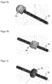
- FIG. 7 illustrates this adaptation of the antenna characteristics and shows the beam characteristics 34 when operating various individual antennas 18 or combinations of individual antennas 16.
- FIGS. 7a and 7b In each case a single antenna is operated at the edge or in the middle of the hollow profile 18. Obviously, a localization to a certain portion of the hollow profile 18 and thus already achieved an essential step.
- FIG. 7c shows FIG. 7c in that the beam characteristic and directivity can be significantly improved by the combined operation of a plurality of individual antennas 16 in order to really detect only transponders 14 in the desired section and to be particularly sensitive to such transponders 14.
Landscapes
- Engineering & Computer Science (AREA)
- Health & Medical Sciences (AREA)
- Toxicology (AREA)
- Physics & Mathematics (AREA)
- Computer Networks & Wireless Communication (AREA)
- Electromagnetism (AREA)
- General Health & Medical Sciences (AREA)
- Artificial Intelligence (AREA)
- Computer Vision & Pattern Recognition (AREA)
- General Physics & Mathematics (AREA)
- Theoretical Computer Science (AREA)
- Variable-Direction Aerials And Aerial Arrays (AREA)
Claims (14)
- Dispositif de lecture RFID (20) avec une antenne (16, 18, 24) pour la reconnaissance d'occupation d'étagères, dans lequel l'antenne (16, 18, 24) comprend un boîtier étiré en longueur (18) et une carte à circuits d'antenne (24) agencée dans le boîtier (18),
caractérisé en ce que
le boîtier (18) comprend un élément profilé creux (18) dans lequel sont réalisés, par enfoncement latéral, des gorges de guidage ou des rails de guidage pour porter des cartes à circuits (24, 26), et en ce que la carte à circuits d'antenne (24) et en supplément au moins une carte à circuits de système (26) avec des circuits du dispositif de lecture RFID (20) pour le pilotage de l'antenne (16, 18, 24) et pour le traitement de signaux RFID reçus avec l'antenne (16, 18, 24) sont mises en place dans le profilé creux (18). - Dispositif de lecture RFID (20) selon la revendication 1,
dans lequel l'élément profilé creux (18) présente sur la totalité de sa longueur la même section transversale, et est en particulier un profilé extrudé. - Dispositif de lecture RFID (20) selon l'une des revendications précédentes,
dans lequel la carte à circuits d'antenne (24) comprend une structure à fentes ou une structure en patch d'antenne. - Dispositif de lecture RFID (20) selon l'une des revendications 1 à 3, dans lequel l'élément profilé creux (18) présente en section transversale un contour extérieur replié avec une pluralité de creux (30) et/ou de saillies (32).
- Dispositif de lecture RFID (20) selon l'une des revendications précédentes,
dans lequel une pluralité de cartes à circuits d'antenne (24a-c) sont mises en place les unes à côté des autres dans l'élément profilé creux (18) et, de cette manière, il est formé une pluralité de modules d'antenne (24a-c, 16). - Dispositif de lecture RFID (20) selon la revendication 6,
dans lequel les modules d'antenne (24a-c, 16) sont susceptibles d'être pilotés individuellement ou en combinaison, afin de lire avec l'antenne des transpondeurs (14) au niveau d'un tronçon déterminé de l'antenne. - Dispositif de lecture RFID (20) selon la revendication 5 ou 6,
qui est réalisé pour associer les uns aux autres des modules d'antenne (24a-c, 16) et des tronçons d'étagères. - Dispositif de lecture RFID (20) selon l'une des revendications 5 à 7, dans lequel l'antenne comprend des éléments d'affichage associés aux modules d'antenne (24a-c, 16).
- Dispositif de lecture RFID (20) selon l'une des revendications précédentes,
dans lequel la carte à circuits d'antenne (24) comprend des éléments d'ajustement pour ajuster les propriétés de l'antenne. - Dispositif de lecture RFID (20) selon l'une des revendications précédentes,
dans lequel l'élément profilé creux (18) est agencé parallèlement aux éléments d'étagères (10) ou est utilisé comme élément d'étagère (10). - Dispositif de lecture RFID selon l'une des revendications précédentes,
dans lequel la carte à circuits de système (26) est simultanément une carte à circuits de couplage (28) pour l'antenne. - Dispositif de lecture RFID (20) selon l'une des revendications précédentes,
dans lequel une pluralité de cartes à circuits de système (26) sont mises en place les unes à côté des autres dans l'élément profilé creux (18). - Dispositif de lecture RFID (20) selon l'une des revendications précédentes,
qui comprend un capteur pour la détection de la présence d'objets, et dans lequel l'antenne (16, 18, 24) fait en particulier office de capteur. - Utilisation d'un dispositif de lecture RFID (20) selon l'une des revendications précédentes pour lire des transpondeurs RFID (14) sur des casiers d'étagères ou des objets dans les casiers d'étagères pour la reconnaissance d'occupation des étagères.
Priority Applications (5)
| Application Number | Priority Date | Filing Date | Title |
|---|---|---|---|
| ES14153736.5T ES2568804T3 (es) | 2014-02-04 | 2014-02-04 | Dispositivo de lectura RFID para la detección de la ocupación de estanterías |
| EP14153736.5A EP2903086B1 (fr) | 2014-02-04 | 2014-02-04 | Dispositif de lecture RFID pour la détection de l'occupation d'étagères |
| DK14153736.5T DK2903086T3 (da) | 2014-02-04 | 2014-02-04 | RFID-læseanordning til detektion af reolindhold |
| US14/601,298 US9323968B2 (en) | 2014-02-04 | 2015-01-21 | RFID reading apparatus for shelf occupancy detection |
| CN201510042469.6A CN104820811B (zh) | 2014-02-04 | 2015-01-28 | 用于识别货架占用情况的rfid读取装置 |
Applications Claiming Priority (1)
| Application Number | Priority Date | Filing Date | Title |
|---|---|---|---|
| EP14153736.5A EP2903086B1 (fr) | 2014-02-04 | 2014-02-04 | Dispositif de lecture RFID pour la détection de l'occupation d'étagères |
Publications (2)
| Publication Number | Publication Date |
|---|---|
| EP2903086A1 EP2903086A1 (fr) | 2015-08-05 |
| EP2903086B1 true EP2903086B1 (fr) | 2016-02-03 |
Family
ID=50068821
Family Applications (1)
| Application Number | Title | Priority Date | Filing Date |
|---|---|---|---|
| EP14153736.5A Active EP2903086B1 (fr) | 2014-02-04 | 2014-02-04 | Dispositif de lecture RFID pour la détection de l'occupation d'étagères |
Country Status (5)
| Country | Link |
|---|---|
| US (1) | US9323968B2 (fr) |
| EP (1) | EP2903086B1 (fr) |
| CN (1) | CN104820811B (fr) |
| DK (1) | DK2903086T3 (fr) |
| ES (1) | ES2568804T3 (fr) |
Cited By (1)
| Publication number | Priority date | Publication date | Assignee | Title |
|---|---|---|---|---|
| US20250329231A1 (en) * | 2022-06-02 | 2025-10-23 | Checkpoint Systems, Inc. | Integrated product surveillance system using eas antenna |
Families Citing this family (21)
| Publication number | Priority date | Publication date | Assignee | Title |
|---|---|---|---|---|
| US10586205B2 (en) | 2015-12-30 | 2020-03-10 | Walmart Apollo, Llc | Apparatus and method for monitoring stock information in a shopping space |
| DE102016207713A1 (de) * | 2016-05-04 | 2017-11-09 | Würth Elektronik Ics Gmbh & Co. Kg | Lagerlogistik Verfahren |
| US9940494B2 (en) | 2016-05-31 | 2018-04-10 | Sick Ag | RFID reading apparatus for shelf occupancy detection |
| DE102016210802A1 (de) * | 2016-06-16 | 2017-12-21 | Ifm Electronic Gmbh | Verfahren zum Betreiben eines Bestückungs- oder Kommissionierungssystems |
| DE202016103887U1 (de) | 2016-07-18 | 2017-10-19 | Sick Ag | RFID-Lesevorrichtung zur Fachbelegungserkennung in einem Regal |
| DE102016113205A1 (de) | 2016-07-18 | 2018-01-18 | Sick Ag | RFID-Lesevorrichtung und Verfahren zur Fachbelegungserkennung in einem Regal |
| EP3291144B1 (fr) | 2016-08-29 | 2018-07-25 | Sick Ag | Dispositif rfid et procede de reconnaissance d'occupation de casier |
| US10586206B2 (en) | 2016-09-22 | 2020-03-10 | Walmart Apollo, Llc | Systems and methods for monitoring conditions on shelves |
| US10417595B2 (en) | 2017-05-05 | 2019-09-17 | DeHart Consulting, LLC | Time-based, demand-pull production |
| CN108682936B (zh) * | 2018-05-03 | 2021-02-02 | Oppo广东移动通信有限公司 | 天线组件、壳体组件及电子设备 |
| WO2020064306A1 (fr) * | 2018-09-27 | 2020-04-02 | Bayer Aktiengesellschaft | Récepteur rfid pour système de suivi d'actifs |
| EP3629219A1 (fr) * | 2018-09-27 | 2020-04-01 | Bayer AG | Récepteur rfid pour système de suivi d'actifs |
| GB201900653D0 (en) * | 2019-01-17 | 2019-03-06 | Ocado Innovation Ltd | RFID tags |
| EP3761216B1 (fr) * | 2019-07-02 | 2022-07-27 | Stanley Black & Decker MEA FZE | Dispositif d'identification ou de suivi d'outils |
| EP3761217B1 (fr) * | 2019-07-02 | 2022-07-27 | Stanley Black & Decker MEA FZE | Dispositif d'identification ou de suivi d'outils |
| DE102019135341A1 (de) * | 2019-12-20 | 2021-06-24 | Bayerische Motoren Werke Aktiengesellschaft | Verfahren zur Überprüfung eines Kommissioniervorgangs |
| WO2021129933A1 (fr) * | 2019-12-23 | 2021-07-01 | Ses-Imagotag Gmbh | Système d'étiquettes électroniques de rayonnage à sous-système de rails de rayonnage |
| CN112163659A (zh) * | 2020-09-09 | 2021-01-01 | 北京智芯微电子科技有限公司 | 微型电子标签以及微型电子标签的制备方法 |
| DE102021107606A1 (de) | 2021-03-25 | 2022-09-29 | Aesculap Ag | Doppelcodierungseinrichtung für in- und außenseitige Containercodierung |
| DE102022202595A1 (de) | 2022-03-16 | 2023-09-21 | Adolf Würth GmbH & Co. KG | Lagerregal und Verfahren zum Verwalten des Inhalts eines Lagerregals |
| CN116902468B (zh) * | 2023-07-25 | 2024-02-20 | 国网江苏省电力有限公司泰州供电分公司 | 一种用于电力物资的仓库识别系统 |
Family Cites Families (17)
| Publication number | Priority date | Publication date | Assignee | Title |
|---|---|---|---|---|
| EP1668741A2 (fr) * | 2003-05-09 | 2006-06-14 | MeadWestvaco Corporation | Appareil et procede permettant d'utiliser une antenne de proximite immediate |
| DE202004003810U1 (de) | 2004-03-11 | 2004-05-13 | Sick Ag | Schutzeinrichtung, insbesondere Lichtgitter |
| US20070090957A1 (en) | 2005-10-25 | 2007-04-26 | M/A-Com, Inc. | RFID antenna rack assembly |
| US7757947B2 (en) | 2006-03-17 | 2010-07-20 | Siemens Aktiengesellschaft | R.F.I.D. enabled storage bin and method for tracking inventory |
| US7310070B1 (en) * | 2006-08-23 | 2007-12-18 | Goliath Solutions, Llc | Radio frequency identification shelf antenna with a distributed pattern for localized tag detection |
| CN101254640A (zh) * | 2007-03-01 | 2008-09-03 | 黄胜昌 | 无线射频辨识模内成型制法及制品 |
| DE102007013237A1 (de) | 2007-03-15 | 2008-09-18 | Joint Analytical Systems Gmbh | Lagersystem |
| US7525487B2 (en) * | 2007-05-17 | 2009-04-28 | Yeon Technologies Co., Ltd. | RFID shelf antennas |
| JP5065780B2 (ja) * | 2007-07-03 | 2012-11-07 | 株式会社日立製作所 | Rfidタグ実装基板 |
| WO2009011601A1 (fr) * | 2007-07-18 | 2009-01-22 | Times-7 Holdings Limited | Antenne à panneau, et procédé de réalisation d'une antenne à panneau |
| US8289163B2 (en) * | 2007-09-27 | 2012-10-16 | 3M Innovative Properties Company | Signal line structure for a radio-frequency identification system |
| KR100942120B1 (ko) * | 2008-02-05 | 2010-02-12 | 엘에스산전 주식회사 | 무선인식(rfid) 리더기 안테나 및 이를 이용한 물품관리 장치 |
| US7986280B2 (en) * | 2008-02-06 | 2011-07-26 | Powerwave Technologies, Inc. | Multi-element broadband omni-directional antenna array |
| JP2010142572A (ja) * | 2008-12-22 | 2010-07-01 | Toshiba Tec Corp | 商品陳列位置アラートシステム及び商品陳列位置アラートプログラム |
| KR20100108124A (ko) | 2009-03-27 | 2010-10-06 | 엘에스산전 주식회사 | 도서관용 모빌랙 및 이를 구비하는 도서관용 rfid 시스템 |
| FR2946169B1 (fr) * | 2009-05-28 | 2013-07-05 | Ingenico Sa | Activation d'un dispositif sans contact par un dispositif capacitif. |
| NL2004775C2 (nl) * | 2009-06-25 | 2010-12-28 | Nedap Nv | Schapantenneconfiguratie. |
-
2014
- 2014-02-04 ES ES14153736.5T patent/ES2568804T3/es active Active
- 2014-02-04 DK DK14153736.5T patent/DK2903086T3/da active
- 2014-02-04 EP EP14153736.5A patent/EP2903086B1/fr active Active
-
2015
- 2015-01-21 US US14/601,298 patent/US9323968B2/en active Active
- 2015-01-28 CN CN201510042469.6A patent/CN104820811B/zh not_active Expired - Fee Related
Cited By (1)
| Publication number | Priority date | Publication date | Assignee | Title |
|---|---|---|---|---|
| US20250329231A1 (en) * | 2022-06-02 | 2025-10-23 | Checkpoint Systems, Inc. | Integrated product surveillance system using eas antenna |
Also Published As
| Publication number | Publication date |
|---|---|
| DK2903086T3 (da) | 2016-03-21 |
| CN104820811B (zh) | 2017-11-17 |
| US9323968B2 (en) | 2016-04-26 |
| ES2568804T3 (es) | 2016-05-04 |
| EP2903086A1 (fr) | 2015-08-05 |
| CN104820811A (zh) | 2015-08-05 |
| US20150220764A1 (en) | 2015-08-06 |
Similar Documents
| Publication | Publication Date | Title |
|---|---|---|
| EP2903086A1 (fr) | Dispositif de lecture RFID pour la détection de l'occupation d'étagères | |
| EP3291144B1 (fr) | Dispositif rfid et procede de reconnaissance d'occupation de casier | |
| DE102009009639B4 (de) | Schaltschrank oder Rack | |
| EP2399438B1 (fr) | Armoire de commande ou baie | |
| EP3376909B1 (fr) | Dispositif de stockage d'un produit en vrac et procédé associé | |
| EP2087455B1 (fr) | Dispositif et procédé d'acquisition de données | |
| EP1449064B1 (fr) | Systeme et procede permettant de detecter et de recompenser le retour d'un chariot de supermarche ou d'un chariot a bagages pris sur un site de rangement | |
| EP3452966B1 (fr) | Procédé de logistique de stockage | |
| EP3657123B1 (fr) | Etagère inclinée et système de controle pour une etagère inclinée | |
| EP3657993B1 (fr) | Palier pour dispositif de stockage avec une barre de capteurs pouvant être disposée sur la face inférieure pour la détection optique d'articles à stocker sur la face supérieure | |
| EP2399437A1 (fr) | Armoire de commande ou baie | |
| EP2580716B1 (fr) | Surveillance du stock de magasins de transit rfid | |
| EP2479719A2 (fr) | Système et procédé de stockage et de surveillance de marchandises à l'aide de la technologie RFID | |
| DE102007018058A1 (de) | RFID-Antennen-System | |
| EP2500850B1 (fr) | Procédé et système destinés à la surveillance d'objets | |
| EP3273382B1 (fr) | Dispositif de lecture rfid et procédé de reconnaissance d'occupation de casier sur une étagère | |
| EP2012263A1 (fr) | Etagère intelligente | |
| WO2022223131A1 (fr) | Appareil de présentation de produit doté d'une structure de rayonnage pour le dépôt d'articles, et doté d'un capteur pour la détection du stock | |
| DE202016103887U1 (de) | RFID-Lesevorrichtung zur Fachbelegungserkennung in einem Regal | |
| EP2479720B1 (fr) | Système et procédé de stockage et de surveillance de marchandises à l'aide de la technologie RFID | |
| AT521357B1 (de) | Warenausgabeautomat | |
| EP3276552A1 (fr) | Système de communication rfid pour la surveillance électronique d'un entrepôt de stockage dynamique | |
| EP4542443A1 (fr) | Dispositif de détection pour récipients remplissables et systèmes d'étagères |
Legal Events
| Date | Code | Title | Description |
|---|---|---|---|
| PUAI | Public reference made under article 153(3) epc to a published international application that has entered the european phase |
Free format text: ORIGINAL CODE: 0009012 |
|
| 17P | Request for examination filed |
Effective date: 20141008 |
|
| AK | Designated contracting states |
Kind code of ref document: A1 Designated state(s): AL AT BE BG CH CY CZ DE DK EE ES FI FR GB GR HR HU IE IS IT LI LT LU LV MC MK MT NL NO PL PT RO RS SE SI SK SM TR |
|
| AX | Request for extension of the european patent |
Extension state: BA ME |
|
| GRAP | Despatch of communication of intention to grant a patent |
Free format text: ORIGINAL CODE: EPIDOSNIGR1 |
|
| INTG | Intention to grant announced |
Effective date: 20150915 |
|
| GRAS | Grant fee paid |
Free format text: ORIGINAL CODE: EPIDOSNIGR3 |
|
| GRAA | (expected) grant |
Free format text: ORIGINAL CODE: 0009210 |
|
| AK | Designated contracting states |
Kind code of ref document: B1 Designated state(s): AL AT BE BG CH CY CZ DE DK EE ES FI FR GB GR HR HU IE IS IT LI LT LU LV MC MK MT NL NO PL PT RO RS SE SI SK SM TR |
|
| REG | Reference to a national code |
Ref country code: GB Ref legal event code: FG4D Free format text: NOT ENGLISH |
|
| REG | Reference to a national code |
Ref country code: AT Ref legal event code: REF Ref document number: 774071 Country of ref document: AT Kind code of ref document: T Effective date: 20160215 Ref country code: CH Ref legal event code: EP |
|
| REG | Reference to a national code |
Ref country code: IE Ref legal event code: FG4D Free format text: LANGUAGE OF EP DOCUMENT: GERMAN |
|
| REG | Reference to a national code |
Ref country code: DE Ref legal event code: R096 Ref document number: 502014000327 Country of ref document: DE |
|
| REG | Reference to a national code |
Ref country code: DK Ref legal event code: T3 Effective date: 20160317 |
|
| REG | Reference to a national code |
Ref country code: FR Ref legal event code: PLFP Year of fee payment: 3 |
|
| REG | Reference to a national code |
Ref country code: NL Ref legal event code: FP |
|
| REG | Reference to a national code |
Ref country code: ES Ref legal event code: FG2A Ref document number: 2568804 Country of ref document: ES Kind code of ref document: T3 Effective date: 20160504 |
|
| REG | Reference to a national code |
Ref country code: LT Ref legal event code: MG4D |
|
| PG25 | Lapsed in a contracting state [announced via postgrant information from national office to epo] |
Ref country code: NO Free format text: LAPSE BECAUSE OF FAILURE TO SUBMIT A TRANSLATION OF THE DESCRIPTION OR TO PAY THE FEE WITHIN THE PRESCRIBED TIME-LIMIT Effective date: 20160503 Ref country code: FI Free format text: LAPSE BECAUSE OF FAILURE TO SUBMIT A TRANSLATION OF THE DESCRIPTION OR TO PAY THE FEE WITHIN THE PRESCRIBED TIME-LIMIT Effective date: 20160203 Ref country code: HR Free format text: LAPSE BECAUSE OF FAILURE TO SUBMIT A TRANSLATION OF THE DESCRIPTION OR TO PAY THE FEE WITHIN THE PRESCRIBED TIME-LIMIT Effective date: 20160203 Ref country code: GR Free format text: LAPSE BECAUSE OF FAILURE TO SUBMIT A TRANSLATION OF THE DESCRIPTION OR TO PAY THE FEE WITHIN THE PRESCRIBED TIME-LIMIT Effective date: 20160504 |
|
| PG25 | Lapsed in a contracting state [announced via postgrant information from national office to epo] |
Ref country code: LV Free format text: LAPSE BECAUSE OF FAILURE TO SUBMIT A TRANSLATION OF THE DESCRIPTION OR TO PAY THE FEE WITHIN THE PRESCRIBED TIME-LIMIT Effective date: 20160203 Ref country code: LT Free format text: LAPSE BECAUSE OF FAILURE TO SUBMIT A TRANSLATION OF THE DESCRIPTION OR TO PAY THE FEE WITHIN THE PRESCRIBED TIME-LIMIT Effective date: 20160203 Ref country code: RS Free format text: LAPSE BECAUSE OF FAILURE TO SUBMIT A TRANSLATION OF THE DESCRIPTION OR TO PAY THE FEE WITHIN THE PRESCRIBED TIME-LIMIT Effective date: 20160203 Ref country code: BE Free format text: LAPSE BECAUSE OF NON-PAYMENT OF DUE FEES Effective date: 20160229 Ref country code: SE Free format text: LAPSE BECAUSE OF FAILURE TO SUBMIT A TRANSLATION OF THE DESCRIPTION OR TO PAY THE FEE WITHIN THE PRESCRIBED TIME-LIMIT Effective date: 20160203 Ref country code: PT Free format text: LAPSE BECAUSE OF FAILURE TO SUBMIT A TRANSLATION OF THE DESCRIPTION OR TO PAY THE FEE WITHIN THE PRESCRIBED TIME-LIMIT Effective date: 20160603 Ref country code: PL Free format text: LAPSE BECAUSE OF FAILURE TO SUBMIT A TRANSLATION OF THE DESCRIPTION OR TO PAY THE FEE WITHIN THE PRESCRIBED TIME-LIMIT Effective date: 20160203 Ref country code: IS Free format text: LAPSE BECAUSE OF FAILURE TO SUBMIT A TRANSLATION OF THE DESCRIPTION OR TO PAY THE FEE WITHIN THE PRESCRIBED TIME-LIMIT Effective date: 20160603 |
|
| PG25 | Lapsed in a contracting state [announced via postgrant information from national office to epo] |
Ref country code: EE Free format text: LAPSE BECAUSE OF FAILURE TO SUBMIT A TRANSLATION OF THE DESCRIPTION OR TO PAY THE FEE WITHIN THE PRESCRIBED TIME-LIMIT Effective date: 20160203 |
|
| REG | Reference to a national code |
Ref country code: DE Ref legal event code: R097 Ref document number: 502014000327 Country of ref document: DE |
|
| PG25 | Lapsed in a contracting state [announced via postgrant information from national office to epo] |
Ref country code: SM Free format text: LAPSE BECAUSE OF FAILURE TO SUBMIT A TRANSLATION OF THE DESCRIPTION OR TO PAY THE FEE WITHIN THE PRESCRIBED TIME-LIMIT Effective date: 20160203 Ref country code: SK Free format text: LAPSE BECAUSE OF FAILURE TO SUBMIT A TRANSLATION OF THE DESCRIPTION OR TO PAY THE FEE WITHIN THE PRESCRIBED TIME-LIMIT Effective date: 20160203 Ref country code: RO Free format text: LAPSE BECAUSE OF FAILURE TO SUBMIT A TRANSLATION OF THE DESCRIPTION OR TO PAY THE FEE WITHIN THE PRESCRIBED TIME-LIMIT Effective date: 20160203 Ref country code: CZ Free format text: LAPSE BECAUSE OF FAILURE TO SUBMIT A TRANSLATION OF THE DESCRIPTION OR TO PAY THE FEE WITHIN THE PRESCRIBED TIME-LIMIT Effective date: 20160203 |
|
| REG | Reference to a national code |
Ref country code: IE Ref legal event code: MM4A |
|
| PLBE | No opposition filed within time limit |
Free format text: ORIGINAL CODE: 0009261 |
|
| STAA | Information on the status of an ep patent application or granted ep patent |
Free format text: STATUS: NO OPPOSITION FILED WITHIN TIME LIMIT |
|
| 26N | No opposition filed |
Effective date: 20161104 |
|
| PG25 | Lapsed in a contracting state [announced via postgrant information from national office to epo] |
Ref country code: IE Free format text: LAPSE BECAUSE OF NON-PAYMENT OF DUE FEES Effective date: 20160204 |
|
| REG | Reference to a national code |
Ref country code: FR Ref legal event code: PLFP Year of fee payment: 4 |
|
| PG25 | Lapsed in a contracting state [announced via postgrant information from national office to epo] |
Ref country code: BG Free format text: LAPSE BECAUSE OF FAILURE TO SUBMIT A TRANSLATION OF THE DESCRIPTION OR TO PAY THE FEE WITHIN THE PRESCRIBED TIME-LIMIT Effective date: 20160503 Ref country code: SI Free format text: LAPSE BECAUSE OF FAILURE TO SUBMIT A TRANSLATION OF THE DESCRIPTION OR TO PAY THE FEE WITHIN THE PRESCRIBED TIME-LIMIT Effective date: 20160203 |
|
| PG25 | Lapsed in a contracting state [announced via postgrant information from national office to epo] |
Ref country code: MT Free format text: LAPSE BECAUSE OF FAILURE TO SUBMIT A TRANSLATION OF THE DESCRIPTION OR TO PAY THE FEE WITHIN THE PRESCRIBED TIME-LIMIT Effective date: 20160203 |
|
| REG | Reference to a national code |
Ref country code: CH Ref legal event code: PL |
|
| PG25 | Lapsed in a contracting state [announced via postgrant information from national office to epo] |
Ref country code: CH Free format text: LAPSE BECAUSE OF NON-PAYMENT OF DUE FEES Effective date: 20170228 Ref country code: LI Free format text: LAPSE BECAUSE OF NON-PAYMENT OF DUE FEES Effective date: 20170228 |
|
| REG | Reference to a national code |
Ref country code: FR Ref legal event code: PLFP Year of fee payment: 5 |
|
| PG25 | Lapsed in a contracting state [announced via postgrant information from national office to epo] |
Ref country code: HU Free format text: LAPSE BECAUSE OF FAILURE TO SUBMIT A TRANSLATION OF THE DESCRIPTION OR TO PAY THE FEE WITHIN THE PRESCRIBED TIME-LIMIT; INVALID AB INITIO Effective date: 20140204 |
|
| PGFP | Annual fee paid to national office [announced via postgrant information from national office to epo] |
Ref country code: TR Payment date: 20180131 Year of fee payment: 5 |
|
| PG25 | Lapsed in a contracting state [announced via postgrant information from national office to epo] |
Ref country code: LU Free format text: LAPSE BECAUSE OF NON-PAYMENT OF DUE FEES Effective date: 20160204 Ref country code: MC Free format text: LAPSE BECAUSE OF FAILURE TO SUBMIT A TRANSLATION OF THE DESCRIPTION OR TO PAY THE FEE WITHIN THE PRESCRIBED TIME-LIMIT Effective date: 20160203 Ref country code: CY Free format text: LAPSE BECAUSE OF FAILURE TO SUBMIT A TRANSLATION OF THE DESCRIPTION OR TO PAY THE FEE WITHIN THE PRESCRIBED TIME-LIMIT Effective date: 20160203 Ref country code: MK Free format text: LAPSE BECAUSE OF FAILURE TO SUBMIT A TRANSLATION OF THE DESCRIPTION OR TO PAY THE FEE WITHIN THE PRESCRIBED TIME-LIMIT Effective date: 20160203 |
|
| PG25 | Lapsed in a contracting state [announced via postgrant information from national office to epo] |
Ref country code: AL Free format text: LAPSE BECAUSE OF FAILURE TO SUBMIT A TRANSLATION OF THE DESCRIPTION OR TO PAY THE FEE WITHIN THE PRESCRIBED TIME-LIMIT Effective date: 20160203 |
|
| PGFP | Annual fee paid to national office [announced via postgrant information from national office to epo] |
Ref country code: GB Payment date: 20190221 Year of fee payment: 6 Ref country code: ES Payment date: 20190319 Year of fee payment: 6 |
|
| PGFP | Annual fee paid to national office [announced via postgrant information from national office to epo] |
Ref country code: SE Payment date: 20190311 Year of fee payment: 18 |
|
| REG | Reference to a national code |
Ref country code: AT Ref legal event code: MM01 Ref document number: 774071 Country of ref document: AT Kind code of ref document: T Effective date: 20190204 |
|
| PG25 | Lapsed in a contracting state [announced via postgrant information from national office to epo] |
Ref country code: AT Free format text: LAPSE BECAUSE OF NON-PAYMENT OF DUE FEES Effective date: 20190204 |
|
| REG | Reference to a national code |
Ref country code: DK Ref legal event code: EBP Effective date: 20200229 |
|
| GBPC | Gb: european patent ceased through non-payment of renewal fee |
Effective date: 20200204 |
|
| PG25 | Lapsed in a contracting state [announced via postgrant information from national office to epo] |
Ref country code: DK Free format text: LAPSE BECAUSE OF NON-PAYMENT OF DUE FEES Effective date: 20200229 Ref country code: GB Free format text: LAPSE BECAUSE OF NON-PAYMENT OF DUE FEES Effective date: 20200204 |
|
| PG25 | Lapsed in a contracting state [announced via postgrant information from national office to epo] |
Ref country code: ES Free format text: LAPSE BECAUSE OF NON-PAYMENT OF DUE FEES Effective date: 20200205 |
|
| PGFP | Annual fee paid to national office [announced via postgrant information from national office to epo] |
Ref country code: NL Payment date: 20220216 Year of fee payment: 9 |
|
| PG25 | Lapsed in a contracting state [announced via postgrant information from national office to epo] |
Ref country code: TR Free format text: LAPSE BECAUSE OF NON-PAYMENT OF DUE FEES Effective date: 20190204 |
|
| REG | Reference to a national code |
Ref country code: NL Ref legal event code: MM Effective date: 20230301 |
|
| PG25 | Lapsed in a contracting state [announced via postgrant information from national office to epo] |
Ref country code: NL Free format text: LAPSE BECAUSE OF NON-PAYMENT OF DUE FEES Effective date: 20230301 |
|
| PGFP | Annual fee paid to national office [announced via postgrant information from national office to epo] |
Ref country code: IT Payment date: 20240229 Year of fee payment: 11 Ref country code: FR Payment date: 20240222 Year of fee payment: 11 |
|
| PGFP | Annual fee paid to national office [announced via postgrant information from national office to epo] |
Ref country code: DE Payment date: 20250218 Year of fee payment: 12 |
|
| PG25 | Lapsed in a contracting state [announced via postgrant information from national office to epo] |
Ref country code: FR Free format text: LAPSE BECAUSE OF NON-PAYMENT OF DUE FEES Effective date: 20250228 Ref country code: IT Free format text: LAPSE BECAUSE OF NON-PAYMENT OF DUE FEES Effective date: 20250204 |