EP2903153A1 - Analyse des vibrations et des bruits d'une machine électrique alimentée par un convertisseur - Google Patents
Analyse des vibrations et des bruits d'une machine électrique alimentée par un convertisseur Download PDFInfo
- Publication number
- EP2903153A1 EP2903153A1 EP14153083.2A EP14153083A EP2903153A1 EP 2903153 A1 EP2903153 A1 EP 2903153A1 EP 14153083 A EP14153083 A EP 14153083A EP 2903153 A1 EP2903153 A1 EP 2903153A1
- Authority
- EP
- European Patent Office
- Prior art keywords
- electric machine
- spectrum
- voltage
- control device
- inverter
- Prior art date
- Legal status (The legal status is an assumption and is not a legal conclusion. Google has not performed a legal analysis and makes no representation as to the accuracy of the status listed.)
- Granted
Links
Images




Classifications
-
- H—ELECTRICITY
- H02—GENERATION; CONVERSION OR DISTRIBUTION OF ELECTRIC POWER
- H02P—CONTROL OR REGULATION OF ELECTRIC MOTORS, ELECTRIC GENERATORS OR DYNAMO-ELECTRIC CONVERTERS; CONTROLLING TRANSFORMERS, REACTORS OR CHOKE COILS
- H02P23/00—Arrangements or methods for the control of AC motors characterised by a control method other than vector control
- H02P23/04—Arrangements or methods for the control of AC motors characterised by a control method other than vector control specially adapted for damping motor oscillations, e.g. for reducing hunting
-
- G—PHYSICS
- G05—CONTROLLING; REGULATING
- G05B—CONTROL OR REGULATING SYSTEMS IN GENERAL; FUNCTIONAL ELEMENTS OF SUCH SYSTEMS; MONITORING OR TESTING ARRANGEMENTS FOR SUCH SYSTEMS OR ELEMENTS
- G05B19/00—Program-control systems
-
- H—ELECTRICITY
- H02—GENERATION; CONVERSION OR DISTRIBUTION OF ELECTRIC POWER
- H02P—CONTROL OR REGULATION OF ELECTRIC MOTORS, ELECTRIC GENERATORS OR DYNAMO-ELECTRIC CONVERTERS; CONTROLLING TRANSFORMERS, REACTORS OR CHOKE COILS
- H02P23/00—Arrangements or methods for the control of AC motors characterised by a control method other than vector control
- H02P23/14—Estimation or adaptation of motor parameters, e.g. rotor time constant, flux, speed, current or voltage
Definitions
- mechanical oscillation is taken to mean both a vibration of an element of the electrical machine (for example a housing or a laminated core) and an acoustic oscillation in the air surrounding the electrical machine.
- mechanical vibration is always used below as a generic term, which includes both a vibration of an element of the electric machine and an acoustic vibration. If only one oscillation of an element of the electrical machine is meant, the term vibration is used below.
- Acoustic vibrations are referred to as such.
- corresponding transfer functions are also referred to as mechanical, vibratory or acoustic transfer functions.
- the present invention further relates to a converter for an electrical machine, via which the electric machine is connected to an electrical supply network, wherein the converter has a control device.
- the present invention further relates to a control program for a software programmable control device of such an inverter, wherein the control program comprises machine code which is directly executable by the control device and whose execution by the control device determines the operation of the inverter.
- additional noises are produced, which are caused by the harmonics of the current.
- the harmonics of the current cause radial force waves in the air gap of the electric machine, that is to say force waves in which the respective force acts in the radial direction of the electric machine.
- the radial force waves are the actual cause of the additional noise.
- the additional noise depends to a large extent on the characteristics of the modulation of the converter, such as the pulse frequency. The additional noise occurs regardless of whether the electric machine is operated as a motor or as a generator.
- the additional noise is mainly due to the fact that the voltage pulsed by the inverter in the winding of the electric machine causes currents which have a high content of harmonics. This results in higher frequency magnetic fields in the air gap of the electric machine, which lead to magnetically caused noises. The higher-frequency magnetic fields also lead to deformations of the laminated core of the electric machine in the radial direction and thereby make it vibrate. These Vibrations are the cause of the additional noise emissions. Often the additional noise occurs to a considerable extent in a frequency range between 1 kHz and 5 kHz. Especially for this frequency range, the human ear is particularly sensitive.
- the acoustic transfer function of the electrical machine can be calculated, for example, with known excitation by the radial force waves by measurements of the sound pressure level taking into account distance of the microphone from the electrical machine and other environmental conditions or even better by direct measurement of sound power - possibly in conjunction with measurements of the sound pressure level ,
- the vibratory transfer function is usually measured by a so-called modal analysis.
- the housing of the electric machine is excited to vibrate by means of a so-called modal hammer.
- the excited vibrations are measured in the prior art by means of vibration sensors.
- the radial force wave with the difference frequency is a pulsating force wave.
- the radial force wave with the sum frequency is a rotating power source having an atomic number equal to twice the number of pole pairs of the fundamental.
- the method proposed in the thesis requires an additional device with power amplifiers, capacitors, inductances, etc. for the superposition of the harmonics that are not present in sine mode. Furthermore, in the overwhelming majority of cases, the method proposed in the thesis can only be realized in a pure test environment, because in practical applications the electrical machines are not sinusoidally fed, but rather are converter-fed. However, the converter feed itself already has higher-frequency components which can overlap with the excitations. As a result, the method of the dissertation in practice is difficult to apply, especially not on site in an already installed system with inverter and electrical machine. In addition, the method proposed in the thesis is laborious.
- the object of the present invention is to provide opportunities to be able to determine the electrical and the mechanical transfer function in a converter-fed electrical machine in a simple and reliable manner.
- the mechanical transfer function may alternatively be a vibratory or an acoustic transfer function.
- the electric machine is designed in three phases.
- harmonics whose frequency corresponds to a divisible by 3 integer multiples of the fundamental frequency can not occur due to the principle.
- those harmonics whose frequency is an odd multiple of the fundamental frequency are of particular importance.
- m is preferably in particular greater than 3, greater than 4 and very particularly preferably greater than 6.
- m may also have larger values, for example 8, 10 or 12. This results in a particularly clean separation of the individual excited vibrations.
- the radial force spectrum in the air gap of the electric machine comprises pulsating and rotating radial force waves.
- each of its own mechanical transfer function is determined for the pulsating and for the rotating radial force waves.
- the mechanical vibration course may be a vibration of an element of the electrical machine and / or a sound radiation.
- the corresponding investigation procedure will be performed in a test environment.
- the determination process is performed by a controller of the inverter in a detection mode of the inverter. This makes it possible in particular to carry out the investigation on site.
- the discovery process can be re-executed each time the system comprising the converter and the electrical machine is connected to one another, ie when a first connection between the converter and the electrical machine takes place or when either the converter or the electrical machine is replaced.
- Inverters thus a two-dimensional field with respective optimized voltage curves as a function of the frequency and the Aus Kunststoffgrades is deposited.
- the modulation method of the converter for example, its switching frequency and the switching pattern can be varied.
- Parameters of the determination method may be, for example, a frequency range for the fundamental of the voltage or components of harmonics of the voltage.
- the optimization method is executed by a controller of the inverter in an optimization mode of the inverter.
- the control device reads out and uses the optimized voltage profiles stored in the converter in the optimization mode.
- execution of the optimization method on site is possible in particular.
- the optimization method can be executed again each time when the system comprising the converter and the electrical machine is connected to one another, ie when a first connection of the converter and the electrical machine takes place or if either the converter or the electrical machine is replaced ,
- an inverter of the aforementioned type is configured in that the control device operates the converter in a normal mode or in a determination mode, that the control device executes a determination method according to the invention in the determination mode and that the control device reads out and uses voltage profiles stored in the converter in the normal mode.
- the control device preferably executes the determination mode in the context of an optimization mode.
- the control device executes an optimization method according to the invention in the optimization mode.
- it reads out and uses the optimized voltage profiles stored in the inverter in the optimization mode.
- control device is designed as a software programmable device.
- control program having the features of claim 14. According to the invention causes the execution of the machine code, that the inverter is designed according to the invention.
- the control program can be supplied to the control device in any way, for example via a computer-computer connection such as a LAN or the Internet. Other interfaces are possible, such as a Profibus interface. Alternatively, it is possible to supply the control program to the control device via a (mobile) data carrier on which the control program is stored in machine-readable form, in particular in electronic form. Regardless of how the control program is supplied to the control device, however, it is stored within the control device in a permanently or temporarily assigned to the control device data carrier.
- an electrical machine 1 is connected via an inverter 2 to an electrical supply network 3.
- the converter 2 consists on the one hand of a power converter 4 and on the other hand of a control device 5 for the power converter 4.
- the supply network 3 is usually a three-phase three-phase network.
- the electric machine 1 is a three-phase machine.
- the converter 2 is designed as a DC link converter.
- by means of the power converter 4 is a three-phase power supply of the electric machine 1. In principle, however, feeds with more than three phases are possible.
- the control device 5 is usually designed as a software programmable device. It therefore has internally on the one hand a processor 6, which executes a control program 7. On the other hand, the control device 5 has a program memory 8, in which the control program 7 is stored in machine-readable form.
- the control program 8 comprises machine code 9, which is directly executable by the control device 5 - more precisely by its processor 6.
- the execution of the machine code 9 by the controller 5 determines the operation of the inverter 2.
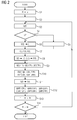
- the execution of the machine code 9 causes the converter 2 to be designed such that it has at least one preliminary method, as related to below FIG. 2 is explained in more detail, preferably also an optimization method, as described below in connection with FIG. 5 and, more preferably, an operating method as described below in connection with FIG. 6 is explained performs.
- the electrical transfer function GE indicates to what extent and possibly also with which phase angle when excited with a (sinusoidal) voltage U with a specific frequency f in the electric machine 1 a current I of the same frequency f is excited.
- the mechanical transfer functions GMP, GMR indicate the extent to which a mechanical oscillation S of the same frequency f is excited in the electrical machine 1 in the case of a (sinusoidal) radial force in the air gap of the electric machine 1, which has a specific frequency f.
- the mechanical vibration S may be, for example, a vibration of a mechanical element of the electric machine 1 or a sound radiation.
- the radial force in the air gap of the electric machine 1 can alternatively be designed as a pulsating radial force wave, as a rotating radial force wave or as a linear combination of a pulsating and a rotating radial force wave.
- the radial force spectrum in the air gap of the electric machine 1 can therefore comprise both pulsating and rotating radial force waves.
- a rotating radial force wave may result in a different stimulation of a mechanical vibration than a pulsating radial force wave of the same frequency. It is therefore necessary to distinguish between a mechanical transfer function GMP for pulsating radial force waves and a mechanical transfer function GMR for rotating radial force waves.
- FIG. 3 shows purely by way of example such a desired voltage spectrum U (f).
- F nf1
- F is the frequency of the considered harmonic
- n a natural number.
- the number m is a natural number.
- FIG. 3 shows at the same time two preferred embodiments of the voltage spectrum U (f).
- the two preferred embodiments can be implemented independently of each other. Preferably however, as shown in FIG. 3 combined together.
- a preferred embodiment is that for immediately successive harmonics of the voltages, the relationship F2 - F1> 2f1 applies.
- F1 and F2 in the above relationship are the frequencies of the two considered harmonics.
- F (6 m +1) f 1
- there is no harmonic contained in the voltage spectrum U (f) which satisfies the condition F for the same value of the number m (6 m -1) f 1 satisfied.
- the reverse exclusion condition applies.
- the other preferred embodiment is that the condition applies to the harmonics that m is greater than 1.
- the number m may, for example, have the value 2, the value 3 or the value 4. Even larger values for the number m are possible, for example, m greater than 6 or m greater than 10. Regardless of the concrete value of the number m, however, occur at least the 4th and 6th harmonic (whose frequencies are equal to five times or seven times the fundamental frequency f1) in the voltage spectrum U (f) are not on.
- the switching angles also define a corresponding temporal voltage curve U (t).
- FIG. 4 shows - purely by way of example - a possible voltage curve U (t).
- the optimum switching times are determined, so that the resulting temporal voltage curve U (t) as far as possible with the desired voltage spectrum U (f) corresponds.
- the converter 2 is activated in a step S6.
- the control device 5 thus controls the power converter 4 in step S6 accordingly.
- the electrical machine 1 is acted upon at the respective frequency f1 by the corresponding voltage curve U (t).
- the control of the converter 2 has the consequence that the electric machine 1 rotates at a speed which depends linearly on the fundamental frequency f1.
- a resulting corresponding respective temporal current profile I (t) is detected in a step S7.
- the detected current profile I (t) can be supplied to the control device 5, for example.
- corresponding vibration sensors 11, 12 a resulting corresponding mechanical vibration course S (t) is detected.
- a vibration sensor 11, 12 is for example a sensor 11 in question, by means of which directly a vibration of a mechanical element of the electric machine 1 is detected.
- the detected mechanical vibration curve S (t) is a vibration of this element of the electric machine 1.
- the detected mechanical vibration course S (t) is a sound radiation of the electric machine 1.
- vibration sensors 11, 12 only one is present. Equally, however, both vibration sensors 11, 12 may be present. Furthermore, optionally in addition to the current waveform I (t) and the waveform S (t) and the voltage curve U (t) can be detected.
- a corresponding respective current spectrum I (f) is determined, for example by Fourier transformation, on the basis of the detected current profile I (t). If, as part of step S7, the voltage curve U (t) is also detected, the (actual) voltage spectrum U (f) is furthermore determined on the basis of the detected voltage curve U (t).
- the electrical transfer function GE is then determined-for example by quotient formation-based on the respective current spectrum I (f) and the respective voltage spectrum U (f) at at least one of the predetermined harmonics of the respective fundamental frequency f1. If, for example, as shown in FIG.
- the voltage spectrum U (f) contains, in addition to the fundamental frequency f1 (among others) the proportion a11 of the tenth harmonic, the electrical transfer function GE can be determined for this frequency, that is to say for the fundamental frequency f1. Analogous procedures are also possible for other harmonics which are contained in the voltage spectrum U (f), for example the 16th or the 22nd harmonic.
- the harmonics in the current spectrum I (f) cause in conjunction with the fundamental in accordance with FIG. 3 in the air gap of the electric machine 1 in each case a rotating radial force shaft FRR and a pulsating radial force wave FRP.
- One of the two radial force waves FRR, FRP occurs at the sum of the frequency of the respective harmonic and the fundamental frequency f1 and at the difference between these two frequencies.
- this harmonic has the inverse direction of rotation compared to the fundamental.
- this harmonic causes, for example, a rotating radial force wave FRR at ten times the fundamental frequency f1 and a pulsating radial force wave FRP at twelve times the fundamental frequency f1.
- this harmonic has the same direction of rotation compared to the fundamental.
- this harmonic for example, a rotating radial force wave FRR at fourteen times the fundamental frequency f1 and a pulsating radial force wave FRP at twelve times the fundamental frequency f1.
- the rotating radial force waves FRR and the pulsating radial force waves FRP are detected in a step S10.
- the determination of the radial force waves FRR, FRP is known to those skilled in the art.
- the determination of the radial force waves FRR, FRP thus takes place on the basis of the respective current spectrum I (f).
- the totality of the determined radial force waves FRR, FRP corresponds to a radial force spectrum FRR (f), FRP (f) in the air gap of the electric machine 1.
- the radial force waves FRR, FRP are, as already mentioned, the actual cause of the magnetically induced mechanical oscillations S of the electrical Machine 1.
- a corresponding respective oscillation spectrum S (f) is determined on the basis of the detected respective mechanical oscillation profile S (t).
- the vibration spectrum S (f) contains the same frequencies as the radial force spectrum FRR (f), FRP (f). It is therefore possible to determine a mechanical transfer function GMP, GMR of the electric machine 1 in a step S12 on the basis of the respective radial force spectrum FRR (f), FRP (f) and the respective oscillation spectrum S (f) for at least one harmonic of the fundamental frequency f1. Again, the determination can be made again by forming the quotient.
- the fundamental frequency f1 corresponds, as already mentioned, with a rotational speed of the electric machine 1. Due to the turning on of the electric machine 1 to the electrical supply network 3 increases during the execution of steps S6 to S12, the rotational speed of the electric machine 1. This is in a Step S13, in which the fundamental frequency f1 is increased by a frequency change ⁇ f. It is possible that for this purpose, the current speed of the electric machine 1 is detected. However, other approaches are possible. The fundamental frequency f1 and hereby corresponding to the rotational speed of the electric machine 1 are thus gradually increased.
- a step S14 it is checked whether the fundamental frequency f1 has reached a final value fe. If this is not the case, the procedure returns to step S3. Otherwise the procedure is FIG. 2 completed. Thus, within the framework of the procedure of FIG. 2 a run-up of the electric machine 1 is performed from an initial speed to a final speed.
- an optimization of the electric machine 1 can be made as such.
- certain elements of the electric machine 1 can be dimensioned differently to mechanical To optimize oscillations of the electric machine 1 itself or a noise emission of the electric machine 1 (to minimize as a rule).
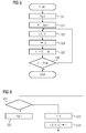
- an electrical and at least one mechanical transfer function GE, GMP, GMR of the electric machine 1 is first determined in a step S21.
- the step S21 corresponds to the entirety of the steps S1 to S14 of FIG. 2 ,
- a temporal voltage curve U (t) is determined for the fundamental frequency f1.
- the determination of step S23 is carried out using the transfer functions GE, GMP, GMR.
- the voltage curve U (t) is determined in such a way that on the one hand it effects the desired operation of the electrical machine 1 -for example at a specific rotational speed and a certain degree of modulation-and on the other hand it is optimized according to a predetermined optimization criterion OK.
- the optimization criterion OK can be determined as needed. As a rule, it will be determined in such a way that the mechanical oscillations S of the electric machine 1 are minimized, at least for certain frequencies.
- the optimized voltage profile U (t) (or those characteristic values such as switching times) determined in step S23 is stored in the converter 2 in a step S24.
- a deposit can take place in a memory 13 of the control device 5.
- the deposit takes place in a two-dimensional field, wherein each one dimension is the frequency corresponding to the speed and the Aus confusegrad.
- a step S25 the fundamental frequency f1 is increased by a frequency change ⁇ f.
- the frequency change ⁇ f of step S25 may correspond to the frequency change ⁇ f of step S11. In principle, however, it can be determined independently.
- a step S26 it is then checked whether the fundamental frequency f1 has reached a maximum frequency fmax. If this is not the case, the procedure returns to step S23. Otherwise the procedure is FIG. 5 completed.
- the optimization process is automated by a facility. It is possible that the parameters of the determination method and the optimization criterion OK of the device are fixed. Alternatively, it is as shown in FIG. 1 possible that the optimization criterion OK and / or parameters of the determination process of the device are specified from the outside. Parameters of the determination method may be, for example, the initial value fa and the final value fe of the fundamental frequency f1, the indication of the harmonics and their proportions ai. Within the scope of the optimization criterion OK, it is possible, for example, to specify specific frequencies or frequency ranges within which a minimization of oscillations S is to take place.
- the device which carries out the determination method and preferably also the optimization method is a special control device for the power converter 4, which is used exclusively for this purpose.
- the device is preferably the control device 5 of the converter 2, which is also used in the context of the normal control of the power converter 4.
- control device 5 can perform only a normal operation and the determination method according to the invention.
- the controller 5 alternately operates the inverter 2 in a detection mode or in a normal mode.
- the controller checks 15 according to FIG. 6 in a step S31, whether to execute the normal mode or the determination mode.
- the controller 5 may check in step S31 whether an appropriate mode is given by an operator (not shown). Under certain circumstances, the control device 5 can also recognize automatically whether it should execute the normal mode or the determination mode.
- step S32 corresponds to the determination mode.
- the control device 5 carries out the determination method according to the invention, which is described above in connection with FIG FIG. 2 was explained.
- Steps S33 and S34 correspond to the normal mode.
- the control device 5 determines - for example based on control commands that are given to the control device 5 by a superordinate device - a speed at which the electric machine 1 is to be operated, and thus a fundamental frequency f1.
- step S34 the control device 5 selects the associated optimized voltage curve U (t) for the corresponding fundamental frequency f1 and the modulation level G and reads this voltage curve U (t) from the memory 13 out.
- the read-out voltage curve U (t) is used by the control device 15 in step S34 for controlling the power converter 4.
- control device 5 of the converter 2 is preferably also able to carry out the optimization method according to the invention.
- control device 5 operates the inverter 2 according to FIG. 7 alternatively in an optimization mode or in normal mode.
- the controller 5 executes an optimization process (as explained above).
- the controller 5 executes the determination mode in the optimization mode.
- the controller 5 checks in a step S36 whether to execute the normal mode or the optimization mode.
- the controller 5 may check in step S31 whether an appropriate mode is given by an operator (not shown).
- the control device 5 can also recognize automatically when it is first connected to the electric machine 1. In this case, an execution of the optimization mode can be triggered automatically and also terminated.
- step S37 the controller 5 executes a procedure as described above in connection with FIG. 5 was explained. In particular, in the context of step S37, the storage of the optimized voltage profiles U (t) for the various fundamental frequencies f1 in the memory 13 takes place. If the control device 5 is to execute the normal mode, it proceeds to steps S33 and S34, which have already been mentioned above With FIG. 6 were explained.
- the present invention has many advantages.
- both the electrical transfer function GE and the mechanical transfer functions GMP, GMR can be measured quickly (in a few minutes) and reliably.
- no additional equipment is required for carrying out the determination method according to the invention and also for carrying out the optimization method according to the invention. Rather, it is possible to use the inverter 2 and its control device 5.
Landscapes
- Engineering & Computer Science (AREA)
- Power Engineering (AREA)
- Physics & Mathematics (AREA)
- General Physics & Mathematics (AREA)
- Automation & Control Theory (AREA)
- Control Of Ac Motors In General (AREA)
- Control Of Electric Motors In General (AREA)
Priority Applications (4)
| Application Number | Priority Date | Filing Date | Title |
|---|---|---|---|
| ES14153083T ES2729799T3 (es) | 2014-01-29 | 2014-01-29 | Análisis de las oscilaciones y los ruidos de una máquina eléctrica alimentada por un convertidor |
| DK14153083.2T DK2903153T3 (da) | 2014-01-29 | 2014-01-29 | Svingnings- og støjanalyse af en omformerforsynet elektrisk maskine |
| EP14153083.2A EP2903153B1 (fr) | 2014-01-29 | 2014-01-29 | Analyse des vibrations et des bruits d'une machine électrique alimentée par un convertisseur |
| CN201510043479.1A CN104808139B (zh) | 2014-01-29 | 2015-01-28 | 变频器供电的电机的振荡分析和噪声分析 |
Applications Claiming Priority (1)
| Application Number | Priority Date | Filing Date | Title |
|---|---|---|---|
| EP14153083.2A EP2903153B1 (fr) | 2014-01-29 | 2014-01-29 | Analyse des vibrations et des bruits d'une machine électrique alimentée par un convertisseur |
Publications (2)
| Publication Number | Publication Date |
|---|---|
| EP2903153A1 true EP2903153A1 (fr) | 2015-08-05 |
| EP2903153B1 EP2903153B1 (fr) | 2019-03-06 |
Family
ID=50002614
Family Applications (1)
| Application Number | Title | Priority Date | Filing Date |
|---|---|---|---|
| EP14153083.2A Active EP2903153B1 (fr) | 2014-01-29 | 2014-01-29 | Analyse des vibrations et des bruits d'une machine électrique alimentée par un convertisseur |
Country Status (4)
| Country | Link |
|---|---|
| EP (1) | EP2903153B1 (fr) |
| CN (1) | CN104808139B (fr) |
| DK (1) | DK2903153T3 (fr) |
| ES (1) | ES2729799T3 (fr) |
Cited By (3)
| Publication number | Priority date | Publication date | Assignee | Title |
|---|---|---|---|---|
| DE102018216327A1 (de) * | 2018-09-25 | 2020-03-26 | Robert Bosch Gmbh | Verfahren zum Betreiben einer elektrischen Antriebseinheit, vorzugsweise zum Verstellen eines Bauteils im Kraftfahrzeug, sowie eine Antriebseinheit zum Ausführen des Verfahrens |
| EP4325717A1 (fr) * | 2022-08-16 | 2024-02-21 | Wobben Properties GmbH | Procédé de commande d'un convertisseur |
| EP4531271A1 (fr) * | 2023-09-29 | 2025-04-02 | Siemens Aktiengesellschaft | Procédé de commande de systèmes d'entraînement et systèmes d'entraînement |
Families Citing this family (2)
| Publication number | Priority date | Publication date | Assignee | Title |
|---|---|---|---|---|
| CN109214125B (zh) * | 2018-10-22 | 2020-06-09 | 华中科技大学 | 一种电机电磁振动噪声的计算方法 |
| CN114355187A (zh) * | 2021-12-15 | 2022-04-15 | 武汉船用电力推进装置研究所(中国船舶重工集团公司第七一二研究所) | 一种电机振动力波测试提取分析方法 |
Citations (2)
| Publication number | Priority date | Publication date | Assignee | Title |
|---|---|---|---|---|
| DE102009056784A1 (de) * | 2009-12-03 | 2011-06-09 | Conti Temic Microelectronic Gmbh | Verfahren und Vorrichtung zum Betrieb eines Elektromotors |
| EP2421148A1 (fr) * | 2010-08-16 | 2012-02-22 | Baumüller Nürnberg GmbH | Dispositif et procédé d'identification des paramètres de référence mécaniques d'un moteur asynchrone triphasé sans utilisation d'encodeur de vitesse |
Family Cites Families (4)
| Publication number | Priority date | Publication date | Assignee | Title |
|---|---|---|---|---|
| PL2625540T3 (pl) * | 2010-10-07 | 2014-07-31 | Abb Research Ltd | Wykrywanie brakującego klina żłobkowego stojana w maszynie elektrycznej |
| ES2428240B1 (es) * | 2012-05-03 | 2015-03-10 | Gamesa Innovation & Tech Sl | Método y Módulo para medir la tasa de cambio de frecuencia de las formas de onda relacionadas con las unidades de convertidor de los aerogeneradores |
| CN202886567U (zh) * | 2012-11-08 | 2013-04-17 | 天津市詹佛斯科技发展有限公司 | 基于网络化虚拟仪器的特种电机测试装置 |
| CN103245913B (zh) * | 2013-04-19 | 2016-04-13 | 上海交通大学 | 大型发电机组次同步振荡信号检测与分析的方法及系统 |
-
2014
- 2014-01-29 EP EP14153083.2A patent/EP2903153B1/fr active Active
- 2014-01-29 DK DK14153083.2T patent/DK2903153T3/da active
- 2014-01-29 ES ES14153083T patent/ES2729799T3/es active Active
-
2015
- 2015-01-28 CN CN201510043479.1A patent/CN104808139B/zh active Active
Patent Citations (2)
| Publication number | Priority date | Publication date | Assignee | Title |
|---|---|---|---|---|
| DE102009056784A1 (de) * | 2009-12-03 | 2011-06-09 | Conti Temic Microelectronic Gmbh | Verfahren und Vorrichtung zum Betrieb eines Elektromotors |
| EP2421148A1 (fr) * | 2010-08-16 | 2012-02-22 | Baumüller Nürnberg GmbH | Dispositif et procédé d'identification des paramètres de référence mécaniques d'un moteur asynchrone triphasé sans utilisation d'encodeur de vitesse |
Cited By (4)
| Publication number | Priority date | Publication date | Assignee | Title |
|---|---|---|---|---|
| DE102018216327A1 (de) * | 2018-09-25 | 2020-03-26 | Robert Bosch Gmbh | Verfahren zum Betreiben einer elektrischen Antriebseinheit, vorzugsweise zum Verstellen eines Bauteils im Kraftfahrzeug, sowie eine Antriebseinheit zum Ausführen des Verfahrens |
| EP4325717A1 (fr) * | 2022-08-16 | 2024-02-21 | Wobben Properties GmbH | Procédé de commande d'un convertisseur |
| EP4531271A1 (fr) * | 2023-09-29 | 2025-04-02 | Siemens Aktiengesellschaft | Procédé de commande de systèmes d'entraînement et systèmes d'entraînement |
| WO2025067801A1 (fr) * | 2023-09-29 | 2025-04-03 | Siemens Aktiengesellschaft | Procédé de commande de systèmes d'entraînement et systèmes d'entraînement |
Also Published As
| Publication number | Publication date |
|---|---|
| EP2903153B1 (fr) | 2019-03-06 |
| CN104808139A (zh) | 2015-07-29 |
| DK2903153T3 (da) | 2019-05-20 |
| ES2729799T3 (es) | 2019-11-06 |
| CN104808139B (zh) | 2019-01-15 |
Similar Documents
| Publication | Publication Date | Title |
|---|---|---|
| DE112011101711B4 (de) | Motorsteuerungsvorrichtung | |
| EP2421148B1 (fr) | Dispositif et procédé d'identification des paramètres de référence mécaniques d'un moteur asynchrone triphasé sans utilisation d'encodeur de vitesse | |
| EP2903153B1 (fr) | Analyse des vibrations et des bruits d'une machine électrique alimentée par un convertisseur | |
| DE102007039697A1 (de) | Verfahren und Vorrichtung zur Kompensation von Schwingungseffekten bei Netzunsymmetrie bei einer doppeltgespeisten Asynchronmaschine | |
| DE112014004230T5 (de) | Frequenzumrichtersteuerungsverfahren zum Unterdrücken von Stromoszillationen eines Induktionsmotors | |
| EP0800265A2 (fr) | Procédé et appareil pour la régulation directe de couple d'une machine à champs tournant | |
| EP3370046A1 (fr) | Procédé et dispositif de détermination de vitesse de rotation de machine | |
| DE102005017073B4 (de) | Steuerverfahren für magnetisch bedingte Geräusche von rotierenden Wechselstrommaschinen | |
| WO2021151950A1 (fr) | Procédé et dispositif de commande d'une machine électrique | |
| EP2757384A2 (fr) | Procédé et dispositif de détection de fautes dans une machine électrique | |
| EP2283572B1 (fr) | Procédé de commande ou de régulation pour un convertisseur | |
| DE112012000323T5 (de) | Umrichtersteuerungssystem | |
| EP2001123A1 (fr) | Procédé de fonctionnement d'une machine rotative triphasée électrique et dispositif d'exécution du procédé | |
| DE102015001147A1 (de) | Motorsteuervorrichtung zur Korrektur eines Interpolationsfehlers einer Positionserfassungseinrichtung | |
| EP3724476B1 (fr) | Procédé et dispositif de détermination d'une position d'angle de rotation d'un vilebrequin d'un moteur à combustion interne | |
| DE102023102396B4 (de) | Regelung einer elektrischen Maschine, insbesondere einer permanenterregten Synchronmaschine, zur Reduktion von Drehmomentschwankungen | |
| EP2816721A1 (fr) | Procédé de fonctionnement d'un dispositif de commande d'entraînement, dispositif doté de moyens pour la réalisation du procédé et dispositif de commande d'entraînement doté d'un tel dispositif | |
| WO2021104753A1 (fr) | Procédé et dispositif d'étalonnage de la commande d'une machine électrique | |
| EP3907568A1 (fr) | Procédé et systèmes de fourniture d'un modèle de simulation d'une machine électrique rotative | |
| DE102020201203A1 (de) | Verfahren und Vorrichtung zur Drehzahlregelung einer elektrischen Maschine für den Antrieb eines Kompressors einer Wärmpepumpe | |
| DE102022212690A1 (de) | Verfahren und Vorrichtung zur Ansteuerung einer elektrischen Maschine | |
| WO2023094352A1 (fr) | Procédé de réduction sonore pendant le fonctionnement d'un moteur électrique, et dispositif de commande de moteur pour commander le fonctionnement d'un moteur électrique impliquant une réduction sonore | |
| WO2022117615A2 (fr) | Procédé pour déterminer une information de correction, procédé pour commander une machine électrique, appareil, dispositif d'entraînement électrique, pompe à chaleur | |
| EP3043467A1 (fr) | Réglage d'un dispositif d'entraînement | |
| DE102019218544A1 (de) | Verfahren und Vorrichtung zur Regelung einer elektrischen Maschine |
Legal Events
| Date | Code | Title | Description |
|---|---|---|---|
| PUAI | Public reference made under article 153(3) epc to a published international application that has entered the european phase |
Free format text: ORIGINAL CODE: 0009012 |
|
| 17P | Request for examination filed |
Effective date: 20140129 |
|
| AK | Designated contracting states |
Kind code of ref document: A1 Designated state(s): AL AT BE BG CH CY CZ DE DK EE ES FI FR GB GR HR HU IE IS IT LI LT LU LV MC MK MT NL NO PL PT RO RS SE SI SK SM TR |
|
| AX | Request for extension of the european patent |
Extension state: BA ME |
|
| 17P | Request for examination filed |
Effective date: 20160107 |
|
| RBV | Designated contracting states (corrected) |
Designated state(s): AL AT BE BG CH CY CZ DE DK EE ES FI FR GB GR HR HU IE IS IT LI LT LU LV MC MK MT NL NO PL PT RO RS SE SI SK SM TR |
|
| RAP1 | Party data changed (applicant data changed or rights of an application transferred) |
Owner name: SIEMENS AKTIENGESELLSCHAFT |
|
| GRAP | Despatch of communication of intention to grant a patent |
Free format text: ORIGINAL CODE: EPIDOSNIGR1 |
|
| STAA | Information on the status of an ep patent application or granted ep patent |
Free format text: STATUS: GRANT OF PATENT IS INTENDED |
|
| INTG | Intention to grant announced |
Effective date: 20181025 |
|
| GRAS | Grant fee paid |
Free format text: ORIGINAL CODE: EPIDOSNIGR3 |
|
| GRAA | (expected) grant |
Free format text: ORIGINAL CODE: 0009210 |
|
| STAA | Information on the status of an ep patent application or granted ep patent |
Free format text: STATUS: THE PATENT HAS BEEN GRANTED |
|
| AK | Designated contracting states |
Kind code of ref document: B1 Designated state(s): AL AT BE BG CH CY CZ DE DK EE ES FI FR GB GR HR HU IE IS IT LI LT LU LV MC MK MT NL NO PL PT RO RS SE SI SK SM TR |
|
| REG | Reference to a national code |
Ref country code: GB Ref legal event code: FG4D Free format text: NOT ENGLISH |
|
| REG | Reference to a national code |
Ref country code: AT Ref legal event code: REF Ref document number: 1105914 Country of ref document: AT Kind code of ref document: T Effective date: 20190315 Ref country code: CH Ref legal event code: EP |
|
| REG | Reference to a national code |
Ref country code: DE Ref legal event code: R096 Ref document number: 502014011003 Country of ref document: DE |
|
| REG | Reference to a national code |
Ref country code: IE Ref legal event code: FG4D Free format text: LANGUAGE OF EP DOCUMENT: GERMAN |
|
| REG | Reference to a national code |
Ref country code: CH Ref legal event code: NV Representative=s name: SIEMENS SCHWEIZ AG, CH |
|
| REG | Reference to a national code |
Ref country code: DK Ref legal event code: T3 Effective date: 20190516 |
|
| REG | Reference to a national code |
Ref country code: SE Ref legal event code: TRGR |
|
| REG | Reference to a national code |
Ref country code: NL Ref legal event code: MP Effective date: 20190306 |
|
| REG | Reference to a national code |
Ref country code: NO Ref legal event code: T2 Effective date: 20190306 |
|
| REG | Reference to a national code |
Ref country code: LT Ref legal event code: MG4D |
|
| PG25 | Lapsed in a contracting state [announced via postgrant information from national office to epo] |
Ref country code: LT Free format text: LAPSE BECAUSE OF FAILURE TO SUBMIT A TRANSLATION OF THE DESCRIPTION OR TO PAY THE FEE WITHIN THE PRESCRIBED TIME-LIMIT Effective date: 20190306 |
|
| PG25 | Lapsed in a contracting state [announced via postgrant information from national office to epo] |
Ref country code: GR Free format text: LAPSE BECAUSE OF FAILURE TO SUBMIT A TRANSLATION OF THE DESCRIPTION OR TO PAY THE FEE WITHIN THE PRESCRIBED TIME-LIMIT Effective date: 20190607 Ref country code: BG Free format text: LAPSE BECAUSE OF FAILURE TO SUBMIT A TRANSLATION OF THE DESCRIPTION OR TO PAY THE FEE WITHIN THE PRESCRIBED TIME-LIMIT Effective date: 20190606 Ref country code: LV Free format text: LAPSE BECAUSE OF FAILURE TO SUBMIT A TRANSLATION OF THE DESCRIPTION OR TO PAY THE FEE WITHIN THE PRESCRIBED TIME-LIMIT Effective date: 20190306 Ref country code: NL Free format text: LAPSE BECAUSE OF FAILURE TO SUBMIT A TRANSLATION OF THE DESCRIPTION OR TO PAY THE FEE WITHIN THE PRESCRIBED TIME-LIMIT Effective date: 20190306 Ref country code: RS Free format text: LAPSE BECAUSE OF FAILURE TO SUBMIT A TRANSLATION OF THE DESCRIPTION OR TO PAY THE FEE WITHIN THE PRESCRIBED TIME-LIMIT Effective date: 20190306 Ref country code: HR Free format text: LAPSE BECAUSE OF FAILURE TO SUBMIT A TRANSLATION OF THE DESCRIPTION OR TO PAY THE FEE WITHIN THE PRESCRIBED TIME-LIMIT Effective date: 20190306 |
|
| PG25 | Lapsed in a contracting state [announced via postgrant information from national office to epo] |
Ref country code: CZ Free format text: LAPSE BECAUSE OF FAILURE TO SUBMIT A TRANSLATION OF THE DESCRIPTION OR TO PAY THE FEE WITHIN THE PRESCRIBED TIME-LIMIT Effective date: 20190306 Ref country code: RO Free format text: LAPSE BECAUSE OF FAILURE TO SUBMIT A TRANSLATION OF THE DESCRIPTION OR TO PAY THE FEE WITHIN THE PRESCRIBED TIME-LIMIT Effective date: 20190306 Ref country code: AL Free format text: LAPSE BECAUSE OF FAILURE TO SUBMIT A TRANSLATION OF THE DESCRIPTION OR TO PAY THE FEE WITHIN THE PRESCRIBED TIME-LIMIT Effective date: 20190306 Ref country code: PT Free format text: LAPSE BECAUSE OF FAILURE TO SUBMIT A TRANSLATION OF THE DESCRIPTION OR TO PAY THE FEE WITHIN THE PRESCRIBED TIME-LIMIT Effective date: 20190706 Ref country code: SK Free format text: LAPSE BECAUSE OF FAILURE TO SUBMIT A TRANSLATION OF THE DESCRIPTION OR TO PAY THE FEE WITHIN THE PRESCRIBED TIME-LIMIT Effective date: 20190306 Ref country code: EE Free format text: LAPSE BECAUSE OF FAILURE TO SUBMIT A TRANSLATION OF THE DESCRIPTION OR TO PAY THE FEE WITHIN THE PRESCRIBED TIME-LIMIT Effective date: 20190306 |
|
| REG | Reference to a national code |
Ref country code: ES Ref legal event code: FG2A Ref document number: 2729799 Country of ref document: ES Kind code of ref document: T3 Effective date: 20191106 |
|
| PG25 | Lapsed in a contracting state [announced via postgrant information from national office to epo] |
Ref country code: PL Free format text: LAPSE BECAUSE OF FAILURE TO SUBMIT A TRANSLATION OF THE DESCRIPTION OR TO PAY THE FEE WITHIN THE PRESCRIBED TIME-LIMIT Effective date: 20190306 Ref country code: SM Free format text: LAPSE BECAUSE OF FAILURE TO SUBMIT A TRANSLATION OF THE DESCRIPTION OR TO PAY THE FEE WITHIN THE PRESCRIBED TIME-LIMIT Effective date: 20190306 |
|
| REG | Reference to a national code |
Ref country code: DE Ref legal event code: R097 Ref document number: 502014011003 Country of ref document: DE |
|
| PG25 | Lapsed in a contracting state [announced via postgrant information from national office to epo] |
Ref country code: IS Free format text: LAPSE BECAUSE OF FAILURE TO SUBMIT A TRANSLATION OF THE DESCRIPTION OR TO PAY THE FEE WITHIN THE PRESCRIBED TIME-LIMIT Effective date: 20190706 |
|
| PLBE | No opposition filed within time limit |
Free format text: ORIGINAL CODE: 0009261 |
|
| STAA | Information on the status of an ep patent application or granted ep patent |
Free format text: STATUS: NO OPPOSITION FILED WITHIN TIME LIMIT |
|
| 26N | No opposition filed |
Effective date: 20191209 |
|
| PG25 | Lapsed in a contracting state [announced via postgrant information from national office to epo] |
Ref country code: SI Free format text: LAPSE BECAUSE OF FAILURE TO SUBMIT A TRANSLATION OF THE DESCRIPTION OR TO PAY THE FEE WITHIN THE PRESCRIBED TIME-LIMIT Effective date: 20190306 |
|
| PG25 | Lapsed in a contracting state [announced via postgrant information from national office to epo] |
Ref country code: TR Free format text: LAPSE BECAUSE OF FAILURE TO SUBMIT A TRANSLATION OF THE DESCRIPTION OR TO PAY THE FEE WITHIN THE PRESCRIBED TIME-LIMIT Effective date: 20190306 |
|
| PGFP | Annual fee paid to national office [announced via postgrant information from national office to epo] |
Ref country code: FI Payment date: 20200122 Year of fee payment: 7 Ref country code: GB Payment date: 20200114 Year of fee payment: 7 Ref country code: SE Payment date: 20200113 Year of fee payment: 7 Ref country code: AT Payment date: 20191212 Year of fee payment: 7 Ref country code: DK Payment date: 20200123 Year of fee payment: 7 |
|
| PGFP | Annual fee paid to national office [announced via postgrant information from national office to epo] |
Ref country code: CH Payment date: 20200402 Year of fee payment: 7 Ref country code: ES Payment date: 20200422 Year of fee payment: 7 |
|
| PG25 | Lapsed in a contracting state [announced via postgrant information from national office to epo] |
Ref country code: MC Free format text: LAPSE BECAUSE OF FAILURE TO SUBMIT A TRANSLATION OF THE DESCRIPTION OR TO PAY THE FEE WITHIN THE PRESCRIBED TIME-LIMIT Effective date: 20190306 |
|
| REG | Reference to a national code |
Ref country code: BE Ref legal event code: MM Effective date: 20200131 |
|
| PG25 | Lapsed in a contracting state [announced via postgrant information from national office to epo] |
Ref country code: LU Free format text: LAPSE BECAUSE OF NON-PAYMENT OF DUE FEES Effective date: 20200129 |
|
| PG25 | Lapsed in a contracting state [announced via postgrant information from national office to epo] |
Ref country code: BE Free format text: LAPSE BECAUSE OF NON-PAYMENT OF DUE FEES Effective date: 20200131 |
|
| PG25 | Lapsed in a contracting state [announced via postgrant information from national office to epo] |
Ref country code: IE Free format text: LAPSE BECAUSE OF NON-PAYMENT OF DUE FEES Effective date: 20200129 |
|
| REG | Reference to a national code |
Ref country code: FI Ref legal event code: MAE |
|
| REG | Reference to a national code |
Ref country code: DK Ref legal event code: EBP Effective date: 20210131 |
|
| REG | Reference to a national code |
Ref country code: CH Ref legal event code: PL Ref country code: SE Ref legal event code: EUG |
|
| REG | Reference to a national code |
Ref country code: AT Ref legal event code: MM01 Ref document number: 1105914 Country of ref document: AT Kind code of ref document: T Effective date: 20210129 |
|
| GBPC | Gb: european patent ceased through non-payment of renewal fee |
Effective date: 20210129 |
|
| PG25 | Lapsed in a contracting state [announced via postgrant information from national office to epo] |
Ref country code: FI Free format text: LAPSE BECAUSE OF NON-PAYMENT OF DUE FEES Effective date: 20210129 Ref country code: AT Free format text: LAPSE BECAUSE OF NON-PAYMENT OF DUE FEES Effective date: 20210129 |
|
| PG25 | Lapsed in a contracting state [announced via postgrant information from national office to epo] |
Ref country code: LI Free format text: LAPSE BECAUSE OF NON-PAYMENT OF DUE FEES Effective date: 20210131 Ref country code: SE Free format text: LAPSE BECAUSE OF NON-PAYMENT OF DUE FEES Effective date: 20210130 Ref country code: GB Free format text: LAPSE BECAUSE OF NON-PAYMENT OF DUE FEES Effective date: 20210129 Ref country code: CH Free format text: LAPSE BECAUSE OF NON-PAYMENT OF DUE FEES Effective date: 20210131 |
|
| PG25 | Lapsed in a contracting state [announced via postgrant information from national office to epo] |
Ref country code: DK Free format text: LAPSE BECAUSE OF NON-PAYMENT OF DUE FEES Effective date: 20210131 |
|
| REG | Reference to a national code |
Ref country code: ES Ref legal event code: FD2A Effective date: 20220427 |
|
| PG25 | Lapsed in a contracting state [announced via postgrant information from national office to epo] |
Ref country code: MT Free format text: LAPSE BECAUSE OF FAILURE TO SUBMIT A TRANSLATION OF THE DESCRIPTION OR TO PAY THE FEE WITHIN THE PRESCRIBED TIME-LIMIT Effective date: 20190306 Ref country code: CY Free format text: LAPSE BECAUSE OF FAILURE TO SUBMIT A TRANSLATION OF THE DESCRIPTION OR TO PAY THE FEE WITHIN THE PRESCRIBED TIME-LIMIT Effective date: 20190306 |
|
| PG25 | Lapsed in a contracting state [announced via postgrant information from national office to epo] |
Ref country code: MK Free format text: LAPSE BECAUSE OF FAILURE TO SUBMIT A TRANSLATION OF THE DESCRIPTION OR TO PAY THE FEE WITHIN THE PRESCRIBED TIME-LIMIT Effective date: 20190306 |
|
| PG25 | Lapsed in a contracting state [announced via postgrant information from national office to epo] |
Ref country code: ES Free format text: LAPSE BECAUSE OF NON-PAYMENT OF DUE FEES Effective date: 20210130 |
|
| P01 | Opt-out of the competence of the unified patent court (upc) registered |
Effective date: 20230510 |
|
| REG | Reference to a national code |
Ref country code: DE Ref legal event code: R081 Ref document number: 502014011003 Country of ref document: DE Owner name: INNOMOTICS GMBH, DE Free format text: FORMER OWNER: SIEMENS AKTIENGESELLSCHAFT, 80333 MUENCHEN, DE |
|
| REG | Reference to a national code |
Ref country code: NO Ref legal event code: CHAD Owner name: LNNOMOTICS GMBH, DE |
|
| REG | Reference to a national code |
Ref country code: DE Ref legal event code: R081 Ref document number: 502014011003 Country of ref document: DE Owner name: INNOMOTICS GMBH, DE Free format text: FORMER OWNER: INNOMOTICS GMBH, 90441 NUERNBERG, DE |
|
| PGFP | Annual fee paid to national office [announced via postgrant information from national office to epo] |
Ref country code: DE Payment date: 20260128 Year of fee payment: 13 Ref country code: NO Payment date: 20260123 Year of fee payment: 13 |
|
| PGFP | Annual fee paid to national office [announced via postgrant information from national office to epo] |
Ref country code: IT Payment date: 20260126 Year of fee payment: 13 |
|
| PGFP | Annual fee paid to national office [announced via postgrant information from national office to epo] |
Ref country code: FR Payment date: 20260123 Year of fee payment: 13 |