EP2904151B1 - Système de transport d'objets par voie ferroviaire - Google Patents
Système de transport d'objets par voie ferroviaire Download PDFInfo
- Publication number
- EP2904151B1 EP2904151B1 EP13786486.4A EP13786486A EP2904151B1 EP 2904151 B1 EP2904151 B1 EP 2904151B1 EP 13786486 A EP13786486 A EP 13786486A EP 2904151 B1 EP2904151 B1 EP 2904151B1
- Authority
- EP
- European Patent Office
- Prior art keywords
- transport
- articles
- railroad
- track
- accordance
- Prior art date
- Legal status (The legal status is an assumption and is not a legal conclusion. Google has not performed a legal analysis and makes no representation as to the accuracy of the status listed.)
- Active
Links
Images

Classifications
-
- E—FIXED CONSTRUCTIONS
- E01—CONSTRUCTION OF ROADS, RAILWAYS, OR BRIDGES
- E01B—PERMANENT WAY; PERMANENT-WAY TOOLS; MACHINES FOR MAKING RAILWAYS OF ALL KINDS
- E01B27/00—Placing, renewing, working, cleaning, or taking-up the ballast, with or without concurrent work on the track; Devices therefor; Packing sleepers
Definitions
- the present invention relates to a system for the rail-bound transport of objects, for example for the transport to and from material to or from railway work vehicles, with several interconnectable railway carriages, each having at least one transport path on which the objects can be moved along the railway carriages and so It is designed that the transport tracks of coupled railway carriages connect to each other, transport bodies being provided for the objects which are designed to be movable along adjacent transport tracks from railway carriages to railway carriages.
- so-called material handling and silo units are available for the delivery and removal of overburden, gravel, sand and the like .
- These are mostly open railcars, the floors of which are equipped with conveyor belts to convey the materials mentioned.
- a transfer conveyor belt is also arranged at one end of these railway carriages, with which the material can be conveyed from carriage to carriage or, after the transfer conveyor belt has swung out, to the side.
- a disadvantage of these known MFS wagons is the use of conveyor belts only on the bottom of the wagons. As a result, considerable friction occurs between the material and the side walls of the wagon during the conveyance, which leads to a high loss of energy and wear due to abrasion. Large motors are therefore required to drive the conveyors. Due to the open design, dirt not only occurs on the car but also on the surroundings. Another disadvantage is that the extraction causes the materials to separate, which is undesirable in the case of materials for underground refurbishment or the new construction of a railroad track.
- transport bodies are provided for the objects, which are designed to be movable along adjacent transport tracks from car to car.
- the transport objects are moved on carriageways, roller conveyors, slideways, suspension railways, overhead conveyors, conveyor belts, conveyor chain conveyors or other conveyors.
- Much less friction occurs during material transport and the energy loss is also comparatively low.
- due to the use of transport bodies there is practically no segregation of the materials.
- Another advantage is that all types of materials, in particular water, small iron, sleepers and fuel can be transported in addition to road material and gravel. This means that these materials can be transported to and from the track in the same way as gravel and sand, and at the same time by filling different transport bodies with different materials.
- the EP 1 254 987 A2 discloses a method for ballast bed refurbishment, in which the removed material is poured from the clearing chain onto a conveyor belt and from there into a container.
- the container can be pushed out from under the conveyor belt by means of a floor conveyor, so that it can be gripped by a gantry crane and placed on the platform of another railroad car.
- DE 27 13 634 A1 discloses a system for removing bulk goods from a track processing machine.
- the bulk material is filled into transport containers by means of a conveyor belt and an unloading chute and then transported away from platform wagons along a train set using a gantry crane.
- the CN 101 475 003 A. discloses a system for track-bound gravel transport, which is an arrangement of two superimposed Includes taxiways for conveying ballast containers. At the end of the system consisting of coupled wagons, the ballast containers are emptied by tipping.
- GB 2 127 377 A discloses a method for ballast bed renewal, in which the overburden is removed from the work site by means of MFS wagons and new ballast is brought in containers to the track-laying machine.
- the containers filled with the new ballast are emptied onto conveyor belts using a gantry crane and then fed to the machine.
- Track construction sites are often designed in such a way that the materials to be installed and removed are transported by rail only over a relatively short distance and, moreover, are taken over by another non-rail-bound logistics system and / or transferred to such a logistics system. Temporary or permanent storage next to the track can also be considered, especially for bulk goods.
- the invention has for its object to provide a system of the type mentioned, which has expanded uses.
- At least one of the railway carriages has a transfer module with a removal device for removing the objects from the transport bodies.
- the contents of the transport bodies can be reloaded or decanted within the transfer module by means of the removal device, so that further transport or further use of the materials in question is possible without carrying the associated transport bodies for this purpose.
- the transfer module has a buffer device for temporarily receiving the objects removed from the transport bodies, wherein a depositing device of the transfer module is preferably designed to remove the objects from the buffer device and to place them next to or behind the railroad car on the ground.
- the objects can be stored in the buffer device, for example a bunker arranged within the transfer module, until e.g. a work machine has processed the material located in the buffer device and the buffer device can thus take up new material again.
- the removal device is capable of removing transport bodies from the transport track and emptying them by tipping them into a bunker which is provided on a lower frame of the railroad car.
- the removal device is designed to empty the transport body away from the transport path. Particularly when the transported objects are bulk goods such as gravel, gravel or sand, emptying the corresponding transport body makes it particularly easy and quick to remove the goods from it.
- the removal device can be designed to tilt the transport body for emptying.
- the transport body is only to be positioned at a desired location, for example above a storage location, and then rotated about a horizontal axis. This can e.g. be accomplished with an automatic handling device.
- the removal device could also be designed to open a flap in the bottom of the transport body for emptying it.
- the removal device can also comprise a gripper which is able to remove objects from a transport body placed at a predetermined access location or to place objects on or in this.
- Transport bodies that are to be emptied as well as loaded can be driven on the transport path to the access point and parked there, so that the gripper can remove or deposit objects.
- the transfer module comprises a pick-up device for picking up objects from the ground or a conveyor device of another railroad car and for inserting the objects into transport bodies located on the transport path.
- a pick-up device for picking up objects from the ground or a conveyor device of another railroad car and for inserting the objects into transport bodies located on the transport path.
- materials can be picked up from a stockpile or from a road vehicle at the storage location and introduced into the transport body of the transport system.
- a further embodiment of the invention provides that a conveying device of the transfer module is designed to transport the objects after removal from the transport bodies to a transfer point which is distant from the transport track and is preferably located outside the railroad car.
- the conveyor device can in particular be a belt conveyor. If necessary, the conveying device can be designed such that it can transfer the objects to further rail vehicles or to road vehicles. Alternatively or additionally, the conveyor device can also be designed to take over objects from a further rail vehicle or from a road vehicle. The conveyor thus enables a particularly quick and easy change between different transport systems.
- the conveying device is designed to transfer the objects to a standard track construction wagon, in particular to a material conveying and silo unit as mentioned above, or to receive them.
- a material conveying and silo unit as mentioned above, or to receive them.
- This takes into account the fact that many known railway work vehicles such as ballast bed cleaning machines and underground renovation machines are unable to take over or deliver materials in transport bodies. Rather, common railway work vehicles mostly have interfaces that are adapted to MFS units.
- a so-called machine transfer module which forms an interface between transport tracks and MFS units, makes it possible to use common track-laying machines in conjunction with a transport system-based logistics system. In this way, complex special developments can be avoided.
- the transfer module is advantageously used on the track construction site between a track construction machine with an MFS interface and the wagon train of the transport body-based one Logistics system arranged.
- the transfer module is thus the link between the MFS interface of the railroad work vehicle, which is designed in a conventional manner, and a train based on transport bodies made of railroad cars.
- the transfer module can also have a plurality of conveying devices arranged next to one another or one above the other, in order, for example, to enable simultaneous forwarding of different material flows.
- a plurality of conveying devices arranged next to one another or one above the other, in order, for example, to enable simultaneous forwarding of different material flows.
- multiple conveyors multiple streams of different materials, such as crushed stone and grain mix, can be transferred simultaneously. It is also possible to transfer various substances such as crushed stone and grain mixture in batches using a conveyor.
- a special embodiment of the invention provides that the conveyor device is designed to transport the objects transversely to the direction of travel of the railroad cars. This makes it possible to transport the objects to a storage location or road vehicle located next to the track. If larger distances are to be bridged here, the conveyor can be designed as a supported boom. It is further preferred that the conveyor device is pivotable.
- the transfer module can be composed of several separable units.
- one of the units can commute with the other railway wagons of the transport system between the construction site and the storage area, while another unit remains at the storage area.
- one of the separable units can be equipped with a receiving device for receiving materials required at the construction site.
- the transfer module has a power supply for the coupled railway carriages.
- the transfer module can have a control station, from which all processes on the transfer module, on the transport tracks of the coupled railway carriages and, if appropriate, the associated railway work vehicle can be controlled and monitored.
- the application requires it, some or all of the processes on the transfer module, the coupled railway wagons of the transport system and, if applicable, on the associated railway work vehicle can be remotely controlled.
- the construction time and the blocking period required for this can be shortened as a result.
- the invention also relates to a system for the rail-bound transport of objects, for example for the transport to and from material to or from railway work vehicles, with a plurality of interconnectable railway carriages, each of which has at least one transport path on which the objects can be moved along the railway carriages and so It is designed that the transport tracks of coupled railway carriages connect to one another, transport bodies being provided for the objects which are designed to be movable along adjacent transport tracks from railway carriages to railway carriages.
- at least one of the railway carriages has a transfer module with a receiving device for receiving objects from the ground or a conveyor device of another railway carriage and for introducing the objects into transport bodies located on the transport path.
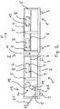
- the in Fig. 1 The train I shown comprises a plurality of railway wagons coupled together, of which only a first railway wagon 1 shown in the picture on the left and a second railway wagon 1 ′ coupled to the right thereof is shown. Depending on the particular application, further railway carriages are connected to the second railway carriage 1 '.
- Each of the railway carriages 1, 1 ' comprises a lower frame 2 with two wheel sets 3.
- an upper frame 4 is provided which is connected to the lower frame 2 via vertical struts 5.
- a transport path 6 is formed on the upper frame 4, on which transport bodies 8 can be moved.
- the transport bodies 8 can be closed boxes, open transport bodies, such as containers or pallets, or machines that are provided on their underside with wheels 9 that roll on the transport track 6.
- the transport body 8 can be moved automatically on the transport track 6.
- the transport bodies 8 are machine-readable Coding 10 provided.
- the method can also be carried out remotely.
- Fig. 1 It can be seen that the transport tracks 6 of the railway carriages 1, 1 'adjoin one another without a paragraph and run horizontally.
- transport rail connections 11 are provided between the railway carriages 1, 1 '.
- the transport bodies 8 can be moved from railway carriages 1, 1 'to railway carriages 1, 1'.
- transport tracks 6 with rollers or the like and transport bodies without wheels 9 such transport track connections 11 can also be dispensed with.
- a transport path could also be formed on the lower frame 2, on which transport bodies 8 can be moved.
- the transport bodies 8 can preferably be moved in both directions on the transport path 6 and optionally on the further transport path of the lower frame 2.
- the first railway carriage 1 comprises a transfer module 13 with a removal device 14.
- the removal device 14 is able to remove transport bodies 8 from the transport track 6 by means of an automatic handling arm 15 and by tipping them into one to empty the bunker 17 provided on the lower frame 2, a flap 19 of the transport body 8 in question possibly being opened.
- the content of the transport body 8 thus reaches the bunker 17, in which it is temporarily stored if necessary.
- the transfer module 13 also has a conveyor 21 in the form of a belt conveyor, which is designed to transport materials located in the bunker 17 out of the bunker 17 and to a storage location 25 on or next to the track. Different from in
- the conveyor 21 could also be designed to transport the materials transversely to the direction of travel F of the train I.
- Fig. 2 shows an alternative embodiment of the invention, which is designed in principle similar to that in Fig. 1 shown train I.
- the conveyor 21 ' is in the embodiment according to Fig. 2 but designed to be MFS compatible.
- the conveying device 21 ' is designed to transfer the materials located in the bunker 17 to a material conveying and silo unit, or to receive them therefrom. This makes it possible in particular to couple a common track-laying machine adapted for the MFS system to the train I from the left and thus to use it with the transport system according to the invention.
- the transfer module 13 could also include a pick-up device for picking up materials from the floor or from a conveyor device of another railroad car and for inserting the objects into transport bodies 8 located on the transport track 6.
- the transfer module 13 can also be designed to discharge liquids such as water or diesel fuel from the transport bodies 8 and to transfer them to a railway work vehicle simultaneously or at different times with the other materials.
- the transfer module 13 enables both the complete supply and the complete disposal of a railway work vehicle such as a ballast and planum-processing machine. Likewise, the transfer module 13 enables the logistical support of a quick conversion machine, eg by supplying new sleepers and disposing of old sleepers.
- the invention also enables the supply and disposal of combination machines, such as a track renewal machine with integrated ballast bed cleaning, also known under the name of quick rebuild cleaning machine, to be carried out in a simple manner.
- combination machines such as a track renewal machine with integrated ballast bed cleaning, also known under the name of quick rebuild cleaning machine, to be carried out in a simple manner.
- new sleepers are brought in and old sleepers are transported away on the transport tracks.
- the screened overburden from the ballast bed cleaning is removed in transport bodies and, if necessary, new ballast is fed in.
Landscapes
- Engineering & Computer Science (AREA)
- Architecture (AREA)
- Civil Engineering (AREA)
- Structural Engineering (AREA)
- Machines For Laying And Maintaining Railways (AREA)
Claims (12)
- Système pour le transport d'objets par voie ferrée, par exemple pour la livraison et l'évacuation de matériel à destination ou en provenance de véhicules de travail ferroviaires, comportant plusieurs wagons de chemin de fer (1, 1') pouvant être accouplés entre eux, qui présentent chacun au moins une piste de transport (6) sur laquelle les objets peuvent être déplacés le long des wagons de chemin de fer (1, 1') et qui est réalisée de telle sorte que les pistes de transport (6) de wagons de chemin de fer (1, 1') accouplés sont adjacentes les unes aux autres, des corps de transport (8) étant prévus pour les objets, qui sont réalisés pour pouvoir être déplacés le long de pistes de transport adjacentes (6) d'un wagon de chemin de fer (1) à un autre wagon de chemin de fer (1'),
dans lequel
l'un au moins des wagons de chemin de fer (1) comprend un module de transfert (13) pourvu d'un dispositif d'enlèvement (14) pour enlever les objets des corps de transport (8),
caractérisé en ce que
le module de transfert (13) comporte un dispositif tampon (17) pour la réception temporaire des objets enlevés des corps de transport (8), le dispositif d'enlèvement (14) étant capable d'enlever les corps de transport (8) de la piste de transport (6) et de les vider dans une cuve (17) en les basculant, ladite cuve étant disposée sur un châssis inférieur (2) du wagon de chemin de fer (1). - Système selon la revendication 1,
caractérisé en ce que
le dispositif d'enlèvement (14) est réalisé pour vider les corps de transport (8) à l'écart de la piste de transport (6). - Système selon la revendication 2,
caractérisé en ce que
le dispositif d'enlèvement (14) est réalisé pour basculer les corps de transport (8) afin de les vider. - Système selon l'une au moins des revendications précédentes,
caractérisé en ce que
le dispositif d'enlèvement (14) comprend un préhenseur capable d'enlever des objets d'un corps de transport (8) placé à un endroit d'accès prédéterminé ou de déposer des objets sur ou dans ledit corps de transport. - Système selon l'une au moins des revendications précédentes,
caractérisé en ce que
le module de transfert (13) comprend un dispositif de réception pour recevoir des objets depuis le sol ou depuis un dispositif de convoyage d'un autre wagon de chemin de fer et pour introduire les objets dans des corps de transport (8) situés sur la piste de transport (6). - Système selon l'une au moins des revendications précédentes,
caractérisé en ce que
un dispositif de dépôt (21) du module de transfert (13) est réalisé pour enlever les objets du dispositif tampon (17) et pour les déposer sur le sol à côté ou derrière le wagon de chemin de fer (1'). - Système selon l'une au moins des revendications précédentes,
caractérisé en ce que
un dispositif de convoyage (21, 21') du module de transfert (11) est réalisé pour transporter les objets, une fois qu'ils sont enlevés des corps de transport (8), jusqu'à un emplacement de transfert éloigné de la piste de transport (6) et situé de préférence à l'extérieur du wagon de chemin de fer (1'). - Système selon la revendication 7,
caractérisé en ce que
le dispositif de convoyage (21') est réalisé pour transférer les objets vers ou les recevoir d'un wagon de construction de voie ferrée, en particulier d'une unité de convoyage et de stockage de matériel. - Système selon la revendication 7 ou 8,
caractérisé en ce que
le module de transfert (13) comprend plusieurs dispositifs de convoyage (21, 21') juxtaposés ou superposés. - Système selon l'une des revendications 7 à 9,
caractérisé en ce que
le dispositif de convoyage (21, 21') est réalisé pour transporter les objets transversalement à la direction de circulation (F) des wagons de chemin de fer (1). - Système selon l'une au moins des revendications précédentes,
caractérisé en ce que
le module de transfert (13) est composé de plusieurs unités séparables. - Système pour le transport d'objets par voie ferrée, par exemple pour la livraison et l'évacuation de matériel à destination ou en provenance de véhicules de travail ferroviaires, comportant plusieurs wagons de chemin de fer (1, 1') pouvant être accouplés entre eux, qui présentent chacun au moins une piste de transport (6) sur laquelle les objets peuvent être déplacés le long des wagons de chemin de fer (1, 1') et qui est réalisée de telle sorte que les pistes de transport (6) de wagons de chemin de fer (1, 1') accouplés sont adjacentes les unes aux autres, des corps de transport (8) étant prévus pour les objets, qui sont réalisés pour pouvoir être déplacés le long de pistes de transport adjacentes (6) d'un wagon de chemin de fer (1) à un autre wagon de chemin de fer (1'),
caractérisé en ce que
l'un au moins des wagons de chemin de fer (1) comprend un module de transfert (13) pourvu d'un dispositif de réception pour recevoir des objets depuis le sol ou depuis un dispositif de convoyage d'un autre wagon de chemin de fer et pour introduire les objets dans des corps de transport (8) situés sur la piste de transport (6).
Applications Claiming Priority (2)
| Application Number | Priority Date | Filing Date | Title |
|---|---|---|---|
| DE102012220877.1A DE102012220877A1 (de) | 2012-11-15 | 2012-11-15 | System zum gleisgebundenen Transport von Gegenständen |
| PCT/EP2013/073101 WO2014075960A1 (fr) | 2012-11-15 | 2013-11-06 | Système de transport d'objets par voie ferroviaire |
Publications (2)
| Publication Number | Publication Date |
|---|---|
| EP2904151A1 EP2904151A1 (fr) | 2015-08-12 |
| EP2904151B1 true EP2904151B1 (fr) | 2020-05-20 |
Family
ID=49546408
Family Applications (1)
| Application Number | Title | Priority Date | Filing Date |
|---|---|---|---|
| EP13786486.4A Active EP2904151B1 (fr) | 2012-11-15 | 2013-11-06 | Système de transport d'objets par voie ferroviaire |
Country Status (3)
| Country | Link |
|---|---|
| EP (1) | EP2904151B1 (fr) |
| DE (1) | DE102012220877A1 (fr) |
| WO (1) | WO2014075960A1 (fr) |
Family Cites Families (6)
| Publication number | Priority date | Publication date | Assignee | Title |
|---|---|---|---|---|
| AT351584B (de) * | 1976-05-31 | 1979-08-10 | Plasser Bahnbaumasch Franz | Zugsverband zur aufnahme, abgabe und zum transport von schuettgut |
| DE3312492A1 (de) * | 1982-09-23 | 1984-03-29 | Franz Plasser Bahnbaumaschinen-Industriegesellschaft mbH, 1010 Wien | Schuettgutverladewagen, insbesondere zur abraumverladung von einer schotterbett-reinigungsmaschine |
| AT375982B (de) * | 1982-12-29 | 1984-09-25 | Plasser Bahnbaumasch Franz | Gleisverfahrbare foerderanlage fuer schuettgut |
| AT4763U3 (de) * | 2001-05-03 | 2002-03-25 | Plasser Bahnbaumasch Franz | Verfahren zur erneuerung einer schotterbettung sowie maschine |
| EP1775190A3 (fr) * | 2005-10-17 | 2007-06-20 | VolkerRail Nederland BV | Renouvellement du lit de ballast d'une voie ferrée |
| CN101475003B (zh) * | 2009-01-19 | 2010-11-10 | 武汉理工大学 | 铁路路基铺设抢险石料自卸列车 |
-
2012
- 2012-11-15 DE DE102012220877.1A patent/DE102012220877A1/de not_active Withdrawn
-
2013
- 2013-11-06 EP EP13786486.4A patent/EP2904151B1/fr active Active
- 2013-11-06 WO PCT/EP2013/073101 patent/WO2014075960A1/fr not_active Ceased
Non-Patent Citations (1)
| Title |
|---|
| None * |
Also Published As
| Publication number | Publication date |
|---|---|
| DE102012220877A1 (de) | 2014-05-15 |
| EP2904151A1 (fr) | 2015-08-12 |
| WO2014075960A1 (fr) | 2014-05-22 |
Similar Documents
| Publication | Publication Date | Title |
|---|---|---|
| AT505403B1 (de) | Maschine zur aufnahme und lagerung von kleineisen eines gleises sowie verfahren | |
| EP2709893B1 (fr) | Système, procédé et wagon pour le transport sur rails d'objets | |
| CH703859B1 (de) | Umschlagvorrichtung für einen Horizontal-Umschlag bei einem Container-Transportsystem | |
| DE19623940B4 (de) | Speicherwagen zur Speicherung von Schüttgut | |
| EP1539619B1 (fr) | Procede pour charger et decharger | |
| DE2713634A1 (de) | Fahrbare maschinenanordnung zum transport von schuettgut | |
| EP2602215B1 (fr) | Système logistique pour le transport combiné de marchandises, ainsi que véhicule sur rail et station de transmission pour celui-ci | |
| EP1249535A2 (fr) | Wagon pour transporter et stocker, méthode pour enlever, stocker et distribuer des matériaux | |
| DE10107306A1 (de) | Verfahren und Vorrichtung zum Ver- bzw. Entladen von auf Paletten angeordnetem, großvolumigem Frachtgut von der Straße auf die Schiene und umgekehrt | |
| DE102010045068B3 (de) | Sanierverfahren für den mehrschichtigen Unterbau bei Bahnstrecken sowie Kopfarbeitswagen | |
| EP2904151B1 (fr) | Système de transport d'objets par voie ferroviaire | |
| DE202020102392U1 (de) | Schienengebundener Plattformwagen mit Förderband und Ladefläche | |
| EP2789519B1 (fr) | Dispositif destiné au transport de matériaux dans la pose de voie | |
| WO2012065841A1 (fr) | Dispositif de manipulation d'unités de transport transmodal | |
| EP3122669B1 (fr) | Procédé pour commander l'alimentation de ballast pendant la rénovation du lit de ballast d'une voie ferrée | |
| EP1254987B1 (fr) | Méthode pour renouveler le ballast et machine | |
| DE3420836A1 (de) | Eisenbahnbauzug zur einbringung einer neuen bettung bei gleisanlagen | |
| EP2022896A1 (fr) | Wagon ferroviaire de chargement de matières en vrac | |
| EP2906753B1 (fr) | Système pour le transport par rail d'objets | |
| DE4339833C2 (de) | Baumaschine für den Neu- bzw. Ausbau oder Rückbau von befestigten Verkehrswegen | |
| EP1249536B1 (fr) | Méthode pour alimenter un chantier en matériaux de construction | |
| DE10128374B4 (de) | Verfahren zur Versorgung einer Linienbaustelle mit Baumaterialien und zugehörige Transport- oder Förderkette, sowie hierbei einsetzbare Klassifizier- und Fraktioniereinrichtung | |
| EP4360983B1 (fr) | Procédé pour effectuer des travaux de voie ferrée | |
| AT507755A1 (de) | Verfahren zum um- bzw. verladen von mindestens einer ladeeinheit | |
| DE3313512A1 (de) | Verfahren und vorrichtung zur bergeentsorgung von bergwerken, insbesondere von steinkohlenaufbereitungen |
Legal Events
| Date | Code | Title | Description |
|---|---|---|---|
| PUAI | Public reference made under article 153(3) epc to a published international application that has entered the european phase |
Free format text: ORIGINAL CODE: 0009012 |
|
| 17P | Request for examination filed |
Effective date: 20150507 |
|
| AK | Designated contracting states |
Kind code of ref document: A1 Designated state(s): AL AT BE BG CH CY CZ DE DK EE ES FI FR GB GR HR HU IE IS IT LI LT LU LV MC MK MT NL NO PL PT RO RS SE SI SK SM TR |
|
| AX | Request for extension of the european patent |
Extension state: BA ME |
|
| DAX | Request for extension of the european patent (deleted) | ||
| STAA | Information on the status of an ep patent application or granted ep patent |
Free format text: STATUS: EXAMINATION IS IN PROGRESS |
|
| 17Q | First examination report despatched |
Effective date: 20181129 |
|
| GRAP | Despatch of communication of intention to grant a patent |
Free format text: ORIGINAL CODE: EPIDOSNIGR1 |
|
| STAA | Information on the status of an ep patent application or granted ep patent |
Free format text: STATUS: GRANT OF PATENT IS INTENDED |
|
| INTG | Intention to grant announced |
Effective date: 20191205 |
|
| GRAS | Grant fee paid |
Free format text: ORIGINAL CODE: EPIDOSNIGR3 |
|
| GRAA | (expected) grant |
Free format text: ORIGINAL CODE: 0009210 |
|
| STAA | Information on the status of an ep patent application or granted ep patent |
Free format text: STATUS: THE PATENT HAS BEEN GRANTED |
|
| AK | Designated contracting states |
Kind code of ref document: B1 Designated state(s): AL AT BE BG CH CY CZ DE DK EE ES FI FR GB GR HR HU IE IS IT LI LT LU LV MC MK MT NL NO PL PT RO RS SE SI SK SM TR |
|
| REG | Reference to a national code |
Ref country code: GB Ref legal event code: FG4D Free format text: NOT ENGLISH |
|
| REG | Reference to a national code |
Ref country code: CH Ref legal event code: EP |
|
| REG | Reference to a national code |
Ref country code: DE Ref legal event code: R096 Ref document number: 502013014723 Country of ref document: DE |
|
| REG | Reference to a national code |
Ref country code: AT Ref legal event code: REF Ref document number: 1272667 Country of ref document: AT Kind code of ref document: T Effective date: 20200615 |
|
| REG | Reference to a national code |
Ref country code: CH Ref legal event code: NV Representative=s name: INTELLECTUAL PROPERTY SERVICES GMBH, CH |
|
| REG | Reference to a national code |
Ref country code: NL Ref legal event code: FP |
|
| REG | Reference to a national code |
Ref country code: LT Ref legal event code: MG4D |
|
| PG25 | Lapsed in a contracting state [announced via postgrant information from national office to epo] |
Ref country code: PT Free format text: LAPSE BECAUSE OF FAILURE TO SUBMIT A TRANSLATION OF THE DESCRIPTION OR TO PAY THE FEE WITHIN THE PRESCRIBED TIME-LIMIT Effective date: 20200921 Ref country code: LT Free format text: LAPSE BECAUSE OF FAILURE TO SUBMIT A TRANSLATION OF THE DESCRIPTION OR TO PAY THE FEE WITHIN THE PRESCRIBED TIME-LIMIT Effective date: 20200520 Ref country code: GR Free format text: LAPSE BECAUSE OF FAILURE TO SUBMIT A TRANSLATION OF THE DESCRIPTION OR TO PAY THE FEE WITHIN THE PRESCRIBED TIME-LIMIT Effective date: 20200821 Ref country code: FI Free format text: LAPSE BECAUSE OF FAILURE TO SUBMIT A TRANSLATION OF THE DESCRIPTION OR TO PAY THE FEE WITHIN THE PRESCRIBED TIME-LIMIT Effective date: 20200520 Ref country code: NO Free format text: LAPSE BECAUSE OF FAILURE TO SUBMIT A TRANSLATION OF THE DESCRIPTION OR TO PAY THE FEE WITHIN THE PRESCRIBED TIME-LIMIT Effective date: 20200820 Ref country code: IS Free format text: LAPSE BECAUSE OF FAILURE TO SUBMIT A TRANSLATION OF THE DESCRIPTION OR TO PAY THE FEE WITHIN THE PRESCRIBED TIME-LIMIT Effective date: 20200920 Ref country code: SE Free format text: LAPSE BECAUSE OF FAILURE TO SUBMIT A TRANSLATION OF THE DESCRIPTION OR TO PAY THE FEE WITHIN THE PRESCRIBED TIME-LIMIT Effective date: 20200520 |
|
| PG25 | Lapsed in a contracting state [announced via postgrant information from national office to epo] |
Ref country code: HR Free format text: LAPSE BECAUSE OF FAILURE TO SUBMIT A TRANSLATION OF THE DESCRIPTION OR TO PAY THE FEE WITHIN THE PRESCRIBED TIME-LIMIT Effective date: 20200520 Ref country code: RS Free format text: LAPSE BECAUSE OF FAILURE TO SUBMIT A TRANSLATION OF THE DESCRIPTION OR TO PAY THE FEE WITHIN THE PRESCRIBED TIME-LIMIT Effective date: 20200520 Ref country code: BG Free format text: LAPSE BECAUSE OF FAILURE TO SUBMIT A TRANSLATION OF THE DESCRIPTION OR TO PAY THE FEE WITHIN THE PRESCRIBED TIME-LIMIT Effective date: 20200820 Ref country code: LV Free format text: LAPSE BECAUSE OF FAILURE TO SUBMIT A TRANSLATION OF THE DESCRIPTION OR TO PAY THE FEE WITHIN THE PRESCRIBED TIME-LIMIT Effective date: 20200520 |
|
| PG25 | Lapsed in a contracting state [announced via postgrant information from national office to epo] |
Ref country code: AL Free format text: LAPSE BECAUSE OF FAILURE TO SUBMIT A TRANSLATION OF THE DESCRIPTION OR TO PAY THE FEE WITHIN THE PRESCRIBED TIME-LIMIT Effective date: 20200520 |
|
| PG25 | Lapsed in a contracting state [announced via postgrant information from national office to epo] |
Ref country code: SM Free format text: LAPSE BECAUSE OF FAILURE TO SUBMIT A TRANSLATION OF THE DESCRIPTION OR TO PAY THE FEE WITHIN THE PRESCRIBED TIME-LIMIT Effective date: 20200520 Ref country code: EE Free format text: LAPSE BECAUSE OF FAILURE TO SUBMIT A TRANSLATION OF THE DESCRIPTION OR TO PAY THE FEE WITHIN THE PRESCRIBED TIME-LIMIT Effective date: 20200520 Ref country code: RO Free format text: LAPSE BECAUSE OF FAILURE TO SUBMIT A TRANSLATION OF THE DESCRIPTION OR TO PAY THE FEE WITHIN THE PRESCRIBED TIME-LIMIT Effective date: 20200520 Ref country code: ES Free format text: LAPSE BECAUSE OF FAILURE TO SUBMIT A TRANSLATION OF THE DESCRIPTION OR TO PAY THE FEE WITHIN THE PRESCRIBED TIME-LIMIT Effective date: 20200520 Ref country code: CZ Free format text: LAPSE BECAUSE OF FAILURE TO SUBMIT A TRANSLATION OF THE DESCRIPTION OR TO PAY THE FEE WITHIN THE PRESCRIBED TIME-LIMIT Effective date: 20200520 Ref country code: IT Free format text: LAPSE BECAUSE OF FAILURE TO SUBMIT A TRANSLATION OF THE DESCRIPTION OR TO PAY THE FEE WITHIN THE PRESCRIBED TIME-LIMIT Effective date: 20200520 Ref country code: DK Free format text: LAPSE BECAUSE OF FAILURE TO SUBMIT A TRANSLATION OF THE DESCRIPTION OR TO PAY THE FEE WITHIN THE PRESCRIBED TIME-LIMIT Effective date: 20200520 |
|
| REG | Reference to a national code |
Ref country code: DE Ref legal event code: R097 Ref document number: 502013014723 Country of ref document: DE |
|
| PG25 | Lapsed in a contracting state [announced via postgrant information from national office to epo] |
Ref country code: PL Free format text: LAPSE BECAUSE OF FAILURE TO SUBMIT A TRANSLATION OF THE DESCRIPTION OR TO PAY THE FEE WITHIN THE PRESCRIBED TIME-LIMIT Effective date: 20200520 Ref country code: SK Free format text: LAPSE BECAUSE OF FAILURE TO SUBMIT A TRANSLATION OF THE DESCRIPTION OR TO PAY THE FEE WITHIN THE PRESCRIBED TIME-LIMIT Effective date: 20200520 |
|
| PLBE | No opposition filed within time limit |
Free format text: ORIGINAL CODE: 0009261 |
|
| STAA | Information on the status of an ep patent application or granted ep patent |
Free format text: STATUS: NO OPPOSITION FILED WITHIN TIME LIMIT |
|
| 26N | No opposition filed |
Effective date: 20210223 |
|
| PG25 | Lapsed in a contracting state [announced via postgrant information from national office to epo] |
Ref country code: SI Free format text: LAPSE BECAUSE OF FAILURE TO SUBMIT A TRANSLATION OF THE DESCRIPTION OR TO PAY THE FEE WITHIN THE PRESCRIBED TIME-LIMIT Effective date: 20200520 |
|
| PG25 | Lapsed in a contracting state [announced via postgrant information from national office to epo] |
Ref country code: MC Free format text: LAPSE BECAUSE OF FAILURE TO SUBMIT A TRANSLATION OF THE DESCRIPTION OR TO PAY THE FEE WITHIN THE PRESCRIBED TIME-LIMIT Effective date: 20200520 |
|
| GBPC | Gb: european patent ceased through non-payment of renewal fee |
Effective date: 20201106 |
|
| PG25 | Lapsed in a contracting state [announced via postgrant information from national office to epo] |
Ref country code: LU Free format text: LAPSE BECAUSE OF NON-PAYMENT OF DUE FEES Effective date: 20201106 |
|
| REG | Reference to a national code |
Ref country code: BE Ref legal event code: MM Effective date: 20201130 |
|
| PG25 | Lapsed in a contracting state [announced via postgrant information from national office to epo] |
Ref country code: IE Free format text: LAPSE BECAUSE OF NON-PAYMENT OF DUE FEES Effective date: 20201106 |
|
| PG25 | Lapsed in a contracting state [announced via postgrant information from national office to epo] |
Ref country code: GB Free format text: LAPSE BECAUSE OF NON-PAYMENT OF DUE FEES Effective date: 20201106 |
|
| PG25 | Lapsed in a contracting state [announced via postgrant information from national office to epo] |
Ref country code: TR Free format text: LAPSE BECAUSE OF FAILURE TO SUBMIT A TRANSLATION OF THE DESCRIPTION OR TO PAY THE FEE WITHIN THE PRESCRIBED TIME-LIMIT Effective date: 20200520 Ref country code: MT Free format text: LAPSE BECAUSE OF FAILURE TO SUBMIT A TRANSLATION OF THE DESCRIPTION OR TO PAY THE FEE WITHIN THE PRESCRIBED TIME-LIMIT Effective date: 20200520 Ref country code: CY Free format text: LAPSE BECAUSE OF FAILURE TO SUBMIT A TRANSLATION OF THE DESCRIPTION OR TO PAY THE FEE WITHIN THE PRESCRIBED TIME-LIMIT Effective date: 20200520 |
|
| PG25 | Lapsed in a contracting state [announced via postgrant information from national office to epo] |
Ref country code: MK Free format text: LAPSE BECAUSE OF FAILURE TO SUBMIT A TRANSLATION OF THE DESCRIPTION OR TO PAY THE FEE WITHIN THE PRESCRIBED TIME-LIMIT Effective date: 20200520 |
|
| PG25 | Lapsed in a contracting state [announced via postgrant information from national office to epo] |
Ref country code: BE Free format text: LAPSE BECAUSE OF NON-PAYMENT OF DUE FEES Effective date: 20201130 |
|
| PGFP | Annual fee paid to national office [announced via postgrant information from national office to epo] |
Ref country code: NL Payment date: 20221118 Year of fee payment: 10 Ref country code: FR Payment date: 20221129 Year of fee payment: 10 Ref country code: AT Payment date: 20221121 Year of fee payment: 10 |
|
| PGFP | Annual fee paid to national office [announced via postgrant information from national office to epo] |
Ref country code: CH Payment date: 20221114 Year of fee payment: 10 |
|
| PGFP | Annual fee paid to national office [announced via postgrant information from national office to epo] |
Ref country code: DE Payment date: 20230127 Year of fee payment: 10 |
|
| REG | Reference to a national code |
Ref country code: DE Ref legal event code: R119 Ref document number: 502013014723 Country of ref document: DE |
|
| REG | Reference to a national code |
Ref country code: CH Ref legal event code: PL |
|
| REG | Reference to a national code |
Ref country code: NL Ref legal event code: MM Effective date: 20231201 |
|
| REG | Reference to a national code |
Ref country code: AT Ref legal event code: MM01 Ref document number: 1272667 Country of ref document: AT Kind code of ref document: T Effective date: 20231106 |
|
| PG25 | Lapsed in a contracting state [announced via postgrant information from national office to epo] |
Ref country code: CH Free format text: LAPSE BECAUSE OF NON-PAYMENT OF DUE FEES Effective date: 20231130 |
|
| PG25 | Lapsed in a contracting state [announced via postgrant information from national office to epo] |
Ref country code: AT Free format text: LAPSE BECAUSE OF NON-PAYMENT OF DUE FEES Effective date: 20231106 |
|
| PG25 | Lapsed in a contracting state [announced via postgrant information from national office to epo] |
Ref country code: CH Free format text: LAPSE BECAUSE OF NON-PAYMENT OF DUE FEES Effective date: 20231130 Ref country code: AT Free format text: LAPSE BECAUSE OF NON-PAYMENT OF DUE FEES Effective date: 20231106 |
|
| PG25 | Lapsed in a contracting state [announced via postgrant information from national office to epo] |
Ref country code: NL Free format text: LAPSE BECAUSE OF NON-PAYMENT OF DUE FEES Effective date: 20231201 |
|
| PG25 | Lapsed in a contracting state [announced via postgrant information from national office to epo] |
Ref country code: NL Free format text: LAPSE BECAUSE OF NON-PAYMENT OF DUE FEES Effective date: 20231201 |
|
| PG25 | Lapsed in a contracting state [announced via postgrant information from national office to epo] |
Ref country code: DE Free format text: LAPSE BECAUSE OF NON-PAYMENT OF DUE FEES Effective date: 20240601 |
|
| PG25 | Lapsed in a contracting state [announced via postgrant information from national office to epo] |
Ref country code: FR Free format text: LAPSE BECAUSE OF NON-PAYMENT OF DUE FEES Effective date: 20231130 |
|
| PG25 | Lapsed in a contracting state [announced via postgrant information from national office to epo] |
Ref country code: FR Free format text: LAPSE BECAUSE OF NON-PAYMENT OF DUE FEES Effective date: 20231130 Ref country code: DE Free format text: LAPSE BECAUSE OF NON-PAYMENT OF DUE FEES Effective date: 20240601 |
|
| PG25 | Lapsed in a contracting state [announced via postgrant information from national office to epo] |
Ref country code: IS Free format text: LAPSE BECAUSE OF NON-PAYMENT OF DUE FEES Effective date: 20200920 |