EP2905151B1 - Pneu - Google Patents
Pneu Download PDFInfo
- Publication number
- EP2905151B1 EP2905151B1 EP15153786.7A EP15153786A EP2905151B1 EP 2905151 B1 EP2905151 B1 EP 2905151B1 EP 15153786 A EP15153786 A EP 15153786A EP 2905151 B1 EP2905151 B1 EP 2905151B1
- Authority
- EP
- European Patent Office
- Prior art keywords
- apex
- tire
- crosslinked rubber
- strip
- pneumatic tire
- Prior art date
- Legal status (The legal status is an assumption and is not a legal conclusion. Google has not performed a legal analysis and makes no representation as to the accuracy of the status listed.)
- Active
Links
Images

Classifications
-
- B—PERFORMING OPERATIONS; TRANSPORTING
- B60—VEHICLES IN GENERAL
- B60C—VEHICLE TYRES; TYRE INFLATION; TYRE CHANGING; CONNECTING VALVES TO INFLATABLE ELASTIC BODIES IN GENERAL; DEVICES OR ARRANGEMENTS RELATED TO TYRES
- B60C15/00—Tyre beads, e.g. ply turn-up or overlap
- B60C15/06—Flipper strips, fillers, or chafing strips and reinforcing layers for the construction of the bead
- B60C15/0603—Flipper strips, fillers, or chafing strips and reinforcing layers for the construction of the bead characterised by features of the bead filler or apex
-
- B—PERFORMING OPERATIONS; TRANSPORTING
- B60—VEHICLES IN GENERAL
- B60C—VEHICLE TYRES; TYRE INFLATION; TYRE CHANGING; CONNECTING VALVES TO INFLATABLE ELASTIC BODIES IN GENERAL; DEVICES OR ARRANGEMENTS RELATED TO TYRES
- B60C15/00—Tyre beads, e.g. ply turn-up or overlap
- B60C15/0009—Tyre beads, e.g. ply turn-up or overlap features of the carcass terminal portion
-
- B—PERFORMING OPERATIONS; TRANSPORTING
- B60—VEHICLES IN GENERAL
- B60C—VEHICLE TYRES; TYRE INFLATION; TYRE CHANGING; CONNECTING VALVES TO INFLATABLE ELASTIC BODIES IN GENERAL; DEVICES OR ARRANGEMENTS RELATED TO TYRES
- B60C15/00—Tyre beads, e.g. ply turn-up or overlap
- B60C15/0009—Tyre beads, e.g. ply turn-up or overlap features of the carcass terminal portion
- B60C15/0054—Tyre beads, e.g. ply turn-up or overlap features of the carcass terminal portion with ply turn-up portion parallel and adjacent to carcass main portion
-
- B—PERFORMING OPERATIONS; TRANSPORTING
- B60—VEHICLES IN GENERAL
- B60C—VEHICLE TYRES; TYRE INFLATION; TYRE CHANGING; CONNECTING VALVES TO INFLATABLE ELASTIC BODIES IN GENERAL; DEVICES OR ARRANGEMENTS RELATED TO TYRES
- B60C15/00—Tyre beads, e.g. ply turn-up or overlap
- B60C15/06—Flipper strips, fillers, or chafing strips and reinforcing layers for the construction of the bead
- B60C15/0603—Flipper strips, fillers, or chafing strips and reinforcing layers for the construction of the bead characterised by features of the bead filler or apex
- B60C15/0607—Flipper strips, fillers, or chafing strips and reinforcing layers for the construction of the bead characterised by features of the bead filler or apex comprising several parts, e.g. made of different rubbers
-
- B—PERFORMING OPERATIONS; TRANSPORTING
- B60—VEHICLES IN GENERAL
- B60C—VEHICLE TYRES; TYRE INFLATION; TYRE CHANGING; CONNECTING VALVES TO INFLATABLE ELASTIC BODIES IN GENERAL; DEVICES OR ARRANGEMENTS RELATED TO TYRES
- B60C15/00—Tyre beads, e.g. ply turn-up or overlap
- B60C15/0009—Tyre beads, e.g. ply turn-up or overlap features of the carcass terminal portion
- B60C2015/009—Height of the carcass terminal portion defined in terms of a numerical value or ratio in proportion to section height
-
- B—PERFORMING OPERATIONS; TRANSPORTING
- B60—VEHICLES IN GENERAL
- B60C—VEHICLE TYRES; TYRE INFLATION; TYRE CHANGING; CONNECTING VALVES TO INFLATABLE ELASTIC BODIES IN GENERAL; DEVICES OR ARRANGEMENTS RELATED TO TYRES
- B60C15/00—Tyre beads, e.g. ply turn-up or overlap
- B60C15/06—Flipper strips, fillers, or chafing strips and reinforcing layers for the construction of the bead
- B60C15/0603—Flipper strips, fillers, or chafing strips and reinforcing layers for the construction of the bead characterised by features of the bead filler or apex
- B60C2015/061—Dimensions of the bead filler in terms of numerical values or ratio in proportion to section height
-
- B—PERFORMING OPERATIONS; TRANSPORTING
- B60—VEHICLES IN GENERAL
- B60C—VEHICLE TYRES; TYRE INFLATION; TYRE CHANGING; CONNECTING VALVES TO INFLATABLE ELASTIC BODIES IN GENERAL; DEVICES OR ARRANGEMENTS RELATED TO TYRES
- B60C15/00—Tyre beads, e.g. ply turn-up or overlap
- B60C15/06—Flipper strips, fillers, or chafing strips and reinforcing layers for the construction of the bead
- B60C2015/0614—Flipper strips, fillers, or chafing strips and reinforcing layers for the construction of the bead characterised by features of the chafer or clinch portion, i.e. the part of the bead contacting the rim
-
- B—PERFORMING OPERATIONS; TRANSPORTING
- B60—VEHICLES IN GENERAL
- B60C—VEHICLE TYRES; TYRE INFLATION; TYRE CHANGING; CONNECTING VALVES TO INFLATABLE ELASTIC BODIES IN GENERAL; DEVICES OR ARRANGEMENTS RELATED TO TYRES
- B60C15/00—Tyre beads, e.g. ply turn-up or overlap
- B60C15/06—Flipper strips, fillers, or chafing strips and reinforcing layers for the construction of the bead
- B60C2015/0617—Flipper strips, fillers, or chafing strips and reinforcing layers for the construction of the bead comprising a cushion rubber other than the chafer or clinch rubber
Definitions
- the present invention relates to a pneumatic tire, more specifically to a pneumatic tire to be mounted on a passenger car.
- a pair of beads is provided for a tire.
- a carcass is set to bridge the beads on both sides.
- a bead has a core and an apex extending from the core in a radially outward direction.
- a carcass ply of the carcass is usually turned up around the core from the axially inner side toward the outer side. Due to such a structure, the carcass ply is divided into a main portion and a turn-up portion.
- the bead portion of a tire is fixed onto a rim. When a car is running, the bead portion receives a greater load. Thus, the durability of the bead portion is important.
- JP2005-255047A discloses an example of such studies.
- Document EP 1 844 956 A2 shows a tire comprising the features of the preamble of independent claim 1.
- a clinch is provided for the axially outer side of a bead.
- a clinch abuts the flange of a rim.
- the aforementioned turn-up portion is positioned between the clinch and the bead.
- a turn-up portion is positioned between the clinch and the bead.
- warping tends to concentrate on the turn-up portion.
- ply loose may occur in the portion.
- a clinch may be made thicker so as to provide a greater flexural rigidity at the bead portion.
- tuning of rigidity adversely affects the steering stability of the tire.
- Providing greater flexural rigidity to the bead portion affects the longitudinal rigidity of a tire.
- a greater longitudinal rigidity not only decreases riding comfort but also increases noise in a frequency range of 80 ⁇ 100 Hz. The quietness of a tire may decrease.
- the above-described thicker clinch increases the mass of a tire. A greater mass adversely affects the rolling resistance of a tire. Thus, such a tire may lower the fuel efficiency of the vehicle.
- the objective of the present invention is to provide a pneumatic tire that exhibits enhanced durability but does not lower steering stability.
- a pneumatic tire includes a tread having an outer surface setting a tread surface, a pair of sidewalls extending from tread edges approximately in a radially inward direction, respectively, a pair of clinches extending from sidewall edges approximately in the radially inward direction, respectively, a pair of beads positioned on axially inner sides of the clinches, respectively, a carcass spreading along an inner side of the tread and sidewalls such that the carcass bridges one of the beads on one side and the other one of the beads on the other side, and a pair of strips extending from the beads along the carcass approximately in a radially outward direction, respectively
- Each of the beads includes a core, a first apex extending from the core in the radially outward direction, and a second apex positioned on an axially outer side of the first apex
- the carcass includes a carcass ply which is turned up around the core from the axially inner side toward an outer side such that the carcass
- a second apex is positioned between the clinch and the turn-up portion of the carcass ply.
- the turn-up portion of the tire is disposed further on an axially inner side than is the turn-up portion of a conventional tire.
- Such positioning suppresses concentration of deformation on the turn-up portion. Since ply loose is suppressed, excellent durability of the tire is achieved.
- the inner edge of the strip of the tire is positioned between the main portion and the turn-up portion, while its outer edge is positioned at the point of maximum width, or on the inner side of such a point, in a radial direction.
- the strip, together with the second apex contributes to planar torsional rigidity of the tire.
- a pneumatic tire according to the present invention has enhanced durability without lowering steering stability.
- FIG 1 shows pneumatic tire 2.
- vertical directions correspond to radial directions of tire 2
- lateral directions correspond to axial directions of tire 2
- directions perpendicular to the drawing sheet are circumferential directions of tire 2.
- Dotted line (CL) in FIG 1 indicates the equatorial plane of tire 2. Except for the tread patterns, tire 2 is shaped to be substantially symmetrical at the equatorial plane.
- Tire 2 includes tread 4, penetrating portion 6, sidewall 8, clinch 10, bead 12, carcass 14, belt 16, edge band 18, inner liner 20, chafer 22 and strip 24.
- Tire 2 is a tubeless tire.
- Tire 2 is for equipping on a passenger car.
- (Pb) in FIG. 1 is a point on the inner surface of tire 2.
- the width of tire 2 reaches its maximum, measured in an axial direction shown on the internal profile.
- the maximum width of tire 2 is measured at point (Pb) to be the length in an axial direction between both sides (outer surfaces of sidewalls 8). In other words, point (Pb) is the point of maximum width of tire 2.
- Tread 4 is in a convex shape in a radially outward direction. Tread 4 forms tread surface 26, which makes contact with the road surface. Grooves 28 are formed in tread 4 and shape a tread pattern. Tread 4 is made up of base layer 30 and cap layer 32. Cap layer 32 is disposed on the radially outer side of base layer 30. Cap layer 32 is laminated on base layer 30. Base layer 30 is made of a crosslinked rubber with excellent adhesiveness. The typical rubber material for base layer 30 is natural rubber. Cap layer 32 is made of a crosslinked rubber with excellent wear resistance, heat resistance and grip capability.
- Penetrating portion 6 penetrates through tread 4. One end of penetrating portion 6 is exposed on tread surface 26. The other end of penetrating portion 6 is in contact with belt 16. Penetrating portion 6 extends along the tire circumference. In other words, penetrating portion 6 is shaped to be a ring. However, instead of a ring shape, it is an option for tire 2 to have multiple penetrating portions 6 separated from each other. Penetrating portion 6 is made of a conductive crosslinked rubber.
- Sidewall 8 extends from the edge of tread 4 in an approximately radially inward direction.
- the radially outer edge of sidewall 8 is bonded to tread 4.
- the radially inner edge of sidewall 8 is bonded to clinch 10.
- Sidewall 8 is made of a crosslinked rubber with excellent cut resistance and weather resistance. Sidewall 8 prevents damage to carcass 14.
- Clinch 10 is positioned on the approximately radially inner side of sidewall 8. Clinch 10 is positioned on the axially outer side of bead 12 and carcass 14. Clinch 10 is made of a crosslinked rubber with excellent wear resistance. Clinch 10 abuts the flange of a rim.
- Bead 12 is positioned on the axially inner side of clinch 10.
- Bead 12 is formed with core 34, first apex 36 and second apex 38.
- Core 34 is in a ring shape, and includes a wound non-stretchable wire. The typical material for the wire is steel.
- First apex 36 extends from core 34 in a radially outward direction.
- First apex 36 tapers in a radially outward direction.
- Second apex 38 is disposed on the axially outer side of first apex 36.
- second apex 38 extends from first apex 36 in a radially outward direction.
- outer edge 40 of second apex 38 is positioned on the radially outer side of outer edge 42 of first apex 36.
- Outer edge 40 of second apex 38 may be positioned on the radially inner side of outer edge 42 of first apex 36.
- First apex 36 of tire 2 is produced by crosslinking a rubber composition.
- first apex 36 is made of a crosslinked rubber.
- a preferred base rubber for the rubber composition is a diene-based rubber.
- diene-based rubbers are natural rubber (NR), polyisoprene (IR), polybutadiene (BR), acrylonitrile-butadiene copolymer (NBR) and polychloroprene (CR). Those rubbers may be used in combination of two or more.
- the rubber composition for forming first apex 36 is preferred to contain sulfur.
- Sulfur causes rubber molecules to crosslink. Together with sulfur or instead of sulfur, another crosslinking aide may be used. Alternatively, electron beams may be used to cause crosslinking.
- the rubber composition for forming first apex 36 is preferred to contain sulfur and a vulcanization accelerator.
- a vulcanization accelerator examples are sulfenamide-based, guanidine-based, thiazole-based, thiuram-based, or dithiocarbamate-based vulcanization accelerators.
- the rubber composition for forming first apex 36 contains reinforcing material.
- Typical reinforcing material is carbon black.
- carbon blacks with fast extruding furnace (FEF), general purpose furnace (GPF), high abrasion furnace (HAF), super abrasion furnace (SAF) and intermediate SAF (ISAF) grades may be used.
- FEF fast extruding furnace
- GPF general purpose furnace
- HAF high abrasion furnace
- SAF super abrasion furnace
- ISAF intermediate SAF
- the amount of carbon black is preferred to be no less than 5 parts by mass based on 100 parts by mass of base rubber material.
- the amount of carbon black is preferred to be no greater than 50 parts by mass.
- silica may be used. In such a case, dry silica or wet silica is used.
- the rubber composition for forming first apex 36 contains a softening agent.
- softening agents are paraffinic, naphthenic, and aromatic processing oils.
- the amount of a softening agent is preferred to be no less than 10 parts by mass based on 100 parts by mass of rubber base.
- the amount of a softening agent is preferred to be no greater than 40 parts by mass.
- Stearic acid, zinc oxide, antiaging agents, wax, crosslinking aides or the like may be added to the rubber composition, if necessary, to form first apex 36.
- Second apex 38 of tire 2 is produced by crosslinking a rubber composition.
- a preferred rubber base for the rubber composition is a diene-based rubber.
- diene-based rubbers are natural rubber (NR), polyisoprene (IR), polybutadiene (BR), acrylonitrile-butadiene copolymer (NBR) and polychloroprene (CR) rubbers. Those rubbers may be used in combination of two or more.
- the rubber composition for forming second apex 38 is preferred to contain sulfur.
- Sulfur causes rubber molecules to crosslink. Together with sulfur or instead of sulfur, another crosslinking aide may be used. Alternatively, electron beams may be used to cause crosslinking.
- the rubber composition for forming second apex 38 is preferred to contain sulfur and a vulcanization accelerator.
- a vulcanization accelerator examples are sulfenamide-based, guanidine-based, thiazole-based, thiuram-based, or dithiocarbamate-based vulcanization accelerators.
- the rubber composition for forming second apex 38 contains reinforcing material.
- Typical reinforcing material is carbon black.
- carbon blacks with FEF, GPF, HAF, ISAF and SAF grades may be used.
- the amount of carbon black is preferred to be no less than 5 parts by mass based on 100 parts by mass of base rubber.
- the amount of carbon black is preferred to be no greater than 50 parts by mass.
- silica may be used. In such a case, dry silica or wet silica is used.
- the rubber composition for forming second apex 38 contains a softening agent.
- softening agents are paraffinic, naphthenic, and aromatic processing oils.
- the amount of a softening agent is preferred to be no less than 10 parts by mass based on 100 parts by mass of base rubber.
- the amount of a softening agent is preferred to be no greater than 40 parts by mass.
- Stearic acid, zinc oxide, antiaging agents, wax, crosslinking aides or the like may be added to the rubber composition, when applicable, to form second apex 38.
- Carcass 14 is formed with carcass ply 44.
- Carcass ply 44 is bridged between beads 12 on both sides.
- Carcass ply 44 is formed along the inner side of tread 4 and sidewalls 8.
- Carcass ply 44 is turned up around core 34 from the axially inner side toward the outer side. Because of such a turned-up structure, carcass ply 44 is divided into main portion 46 and turn-up portion 48.
- edge 50 of turn-up portion 48 is positioned on the radially inner side of point (Pb) of maximum width.
- Edge 50 of turn-up portion 48 is positioned on the radially inner side of outer edge 52 of clinch 10.
- Edge 50 of turn-up portion 48 is positioned between inner edge 54 and outer edge 40 of second apex 38 in a radial direction.
- Carcass 14 has a so-called "low turn-up structure.”
- Carcass ply 44 is made of multiple cords arranged parallel to each other and of topping rubber. The absolute value of the angle each cord makes with respect to the equatorial plane is 75 ⁇ 90 degrees. In other words, carcass 14 has a radial structure.
- Cords are made of organic fibers. Preferred examples of organic fibers are polyester fibers, nylon fibers, rayon fibers, polyethylene naphthalate fibers, and aramid fibers.
- Carcass 14 may be formed with two or more sheets of carcass ply 44. However, carcass 14 is preferred to be formed with one sheet of carcass ply 44, considering the impact on the tire mass.
- Belt 16 is disposed on the radially inner side of tread 4.
- Belt 16 is laminated on carcass 14.
- Belt 16 reinforces carcass 14.
- Belt 16 is made up of inner layer 56 and outer layer 58.
- the width of inner layer 56 is slightly greater than the width of outer layer 58 in an axial direction.
- inner layer 56 and outer layer 58 are each made of multiple cords arranged parallel to each other and of topping rubber. Each cord inclines to the equatorial plane.
- the absolute value of the inclination angle is at least 10 degrees but no greater than 35 degrees.
- the inclination direction of cords in inner layer 56 is opposite the inclination direction of cords in outer layer 58.
- the preferred material of cords is steel. Alternatively, organic fibers may be used for cords.
- the width in an axial direction of belt 16 is preferred to be at least 0.7 times the maximum width of tire 2. It is an option for belt 16 to have three or more layers.
- Edge band 18 is disposed on the radially outer side of belt 16 and near the edge of belt 16.
- edge band 18 is made of cords and topping rubber.
- the cords are helically wound.
- the band has a so-called jointless structure.
- the cords extend in substantially a circumferential direction of the tire.
- the angle of the cords with respect to the circumference is 5 degrees or less, preferably 2 degrees or less. Since the edge of belt 16 is bound by the cords, lifting is suppressed at belt 16.
- the cords are made of organic fibers. Preferred examples of organic fibers are nylon fibers, polyester fibers, rayon fibers, polyethylene naphthalate fibers and aramid fibers.
- Inner liner 20 is disposed on the inner side of carcass 14. Inner liner 20 is bonded to the inner surface of carcass 14. Inner liner 20 is made of a crosslinked rubber with excellent air shielding properties.
- the typical base rubber for inner liner 20 is butyl rubber or halogenated butyl rubber. Inner liner 20 retains the inflation pressure of tire 2.
- Chafer 22 is disposed near bead 12. When tire 22 is mounted on a rim, chafer 22 abuts the rim. Because of such a structure, the vicinity of bead 12 is protected.
- chafer 22 is made of cloth and rubber impregnated in the cloth. It is an option for chafer 22 to be integrated with clinch 10. In such a case, the material for chafer 22 is the same as that for clinch 10.
- Strip 24 is disposed on the axially outer side of main portion 46 of carcass ply 44. Strip 24 extends from bead 12 along main portion 46 in an approximately radially outward direction.
- the outer edge 60 of strip 24 is positioned on the radially outer side of outer edge 52 of clinch 10.
- the inner edge 62 of strip 24 is positioned on the radially inner side of outer edge 40 of second apex 38.
- Strip 24 of tire 2 is produced by cross-linking a rubber composition.
- a preferred base rubber for the rubber composition is a diene-based rubber.
- diene-based rubbers are natural rubber (NR), polyisoprene (IR), polybutadiene (BR), acrylonitrile-butadiene copolymer (NBR) and polychloroprene (CR) rubbers. Those rubbers may be used in combination of two or more.
- the rubber composition for forming strip 24 is preferred to contain sulfur.
- Sulfur causes rubber molecules to crosslink. Together with sulfur or instead of sulfur, another crosslinking aide may be used. Alternatively, electron beams may be used to cause crosslinking.
- the rubber composition for forming strip 24 is preferred to contain sulfur and a vulcanization accelerator.
- a vulcanization accelerator examples are sulfenamide-based, guanidine-based, thiazole-based, thiuram-based, or dithiocarbamate-based vulcanization accelerators.
- the rubber composition for forming strip 24 contains reinforcing material.
- Typical reinforcing material is carbon black.
- carbon blacks such as FEF, GPF, HAF, ISAF and SAF grade carbon black may be used.
- the amount of carbon black is preferred to be no less than 5 parts by mass based on 100 parts by mass of base rubber.
- the amount of carbon black is preferred to be no greater than 50 parts by mass.
- silica may be used. In such a case, dry silica or wet silica is used.
- the rubber composition for forming strip 24 contains a softening agent.
- softening agents are paraffinic, naphthenic and aromatic processing oils.
- the amount of a softening agent is preferred to be no less than 10 parts by mass based on 100 parts by mass of base rubber.
- the amount of a softening agent is preferred to be no greater than 40 parts by mass.
- Stearic acid, zinc oxide, antiaging agents, wax, crosslinking aides or the like may be added to the rubber composition for forming strip 24.
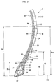
- FIG 2 is a view showing part of tire 2 in FIG 1 .
- FIG 2 shows the vicinity of bead 12 of tire 2.
- vertical directions correspond to the radial directions of tire 2
- lateral directions correspond to the axial directions of tire 2
- directions perpendicular to the drawing sheet correspond to circumferential directions of tire 2.
- second apex 38 is disposed between clinch 10 and turn-up portion 48 of carcass ply 44.
- Turn-up portion 48 of tire 2 is positioned further on an axially inner side than is the turn-up portion of a conventional tire.
- Such a structure suppresses concentration of deformation on turn-up portion 48. Accordingly, since ply loose is suppressed from occurring, durability of tire 2 is excellent.
- the inner edge 62 of strip 24 in tire 2 is positioned between main portion 46 and turn-up portion 48 of carcass ply 44.
- strip 24 extends from bead 12 along main portion 46 in an approximately radially outward direction.
- the position of outer edge 60 of strip 24 corresponds to point (Pb) of maximum width of tire 2, or the position is located on the inner side of point (Pb) of maximum width, in a radial direction.
- strip 24 contributes to the planar torsional rigidity of tire 2. Since outer edge 40 of second apex 38 of tire 2 is positioned on the radially inner side of outer edge 60 of strip 24, strip 24 and second apex 38 properly contribute to the planar torsional rigidity of tire 2.
- the steering stability of tire 2 is properly maintained by strip 24 and second apex 38. Abnormal deformation of tire 2 is suppressed by strip 24 and second apex 38. Strip 24 and second apex 38 contribute to the durability of tire 2. According to an embodiment of the present invention, a pneumatic tire with enhanced durability is obtained without lowering steering stability.
- the position of outer edge 60 of strip 24 corresponds to point (Pb) of maximum width of tire 2, or the position is located on the inner side of point (Pb) of maximum width, in a radial direction. Due to such a position, strip 24 has less impact on rolling resistance. Since the rolling resistance is properly adjusted, tire 2 contributes to lowering the fuel consumption of the vehicle.
- outer edge 42 of first apex 36 is preferred to be on the radially inner side of outer edge 40 of second apex 38.
- a smaller first apex 36 is achieved.
- a smaller first apex 36 provides carcass ply 44 with a proper outline (also referred to as a case line). More specifically, in a cross section perpendicular to the circumference of tire 22, the outline of carcass ply 44 comes closer to a single arc. Such an outline suppresses concentration of deformation.
- a smaller first apex 36 contributes to enhancing durability.
- the entire portion of sidewall 8 warps properly. Sidewall 8 as a whole contributes effectively to the rigidity of tire 2. Such warping contributes to the steering stability of tire 2.
- a smaller first apex 36 reduces volume in the vicinity of bead 12. A smaller volume makes the portion of bead 12 softer. A softer structure affects the longitudinal rigidity of tire 2. Since a decrease in the longitudinal rigidity reduces vibration, noise decreases in tire 2. Especially, a smaller first apex 36 is effective in reducing noise in a frequency range of 80 ⁇ 100 Hz. Thus, tire 2 exhibits excellent quietness. Moreover, a smaller first apex 36 decreases the mass of tire 2. A smaller mass of tire 2 lowers the rolling resistance of tire 2. Tire 2 with less rolling resistance contributes to lowering the fuel consumption of the vehicle.
- the complex elastic modulus (E2) of second apex 38 is at least 60 MPa but no greater than 70 MPa in tire 2.
- modulus (E2) is set at 60 MPa or greater, second apex 38 contributes to planar torsional rigidity.
- Tire 2 exhibits excellent steering stability.
- modulus (E2) is set at 70 MPa or less, second apex 38 has less impact on the rigidity of tire 2. The riding comfort of the vehicle is properly maintained.
- the loss tangent (T2) of second apex 38 in tire 2 is preferred to be 0.18 or lower.
- loss tangent (T2) is set at 0.18 or lower, heat generation is suppressed in second apex 38.
- Second apex 38 contributes to durability. Since less heat generation in tire 2 lowers rolling resistance, tire 2 contributes to a decrease in the fuel consumption of the vehicle. From that viewpoint, loss tangent (T2) is more preferred to be 0.14 or lower. Since a smaller loss tangent (T2) is preferred, a lower limit is not set for loss tangent (T2).
- complex elastic modulus (E2) and loss tangent (T2) of second apex 38 are measured according to the standards in "JIS K 6394.”
- the measurement conditions are as follows.
- the later-described complex elastic modulus (E1) and loss tangent (T1) of first apex 36, as well as the complex elastic modulus (Es) and loss tangent (Ts) of strip 24, are also measured the same as complex elastic modulus (E2) and loss tangent (T2).
- VESF-3 visco-elastic spectrometer
- the complex elastic modulus (E1) of first apex 36 in tire 2 is preferred to be at least 60 MPa but no greater than 70 MPa.
- first apex 36 contributes to supporting tire 2.
- Tire 2 exhibits excellent steering stability.
- modulus (E1) is set at 70 MPa or less, first apex 36 has less impact on the rigidity of tire 2. The riding comfort of the vehicle is properly maintained.
- the loss tangent (T1) of first apex 36 in tire 2 is preferred to be 0.18 or lower.
- loss tangent (T1) is set at 0.18 or lower, heat generation is suppressed in first apex 36.
- First apex 36 contributes to durability. Since less heat generation lowers the rolling resistance of tire 2, tire 2 contributes to a decrease in the fuel consumption of the vehicle. From that viewpoint, loss tangent (T1) is more preferred to be 0.14 or lower. Since a lower loss tangent (T1) is preferred, a lower limit is not set for loss tangent (T1).
- the complex elastic modulus (Es) of strip 24 is at least 60 MPa but no greater than 70 MPa in tire 2.
- modulus (Es) is at 60 MPa or greater, strip 24 contributes to planar torsional rigidity.
- Tire 2 exhibits excellent steering stability.
- modulus (Es) is set at 70 MPa or less, strip 24 has less impact on the rigidity of tire 2. The riding comfort of the vehicle is properly maintained when it is equipped with tire 2.
- the loss tangent (Ts) of strip 24 in tire 2 is preferred to be 0.18 or lower.
- Ts loss tangent
- Strip 24 contributes to durability. Since less heat generation lowers the rolling resistance of tire 2, tire 2 contributes to a decrease in the fuel consumption of the vehicle. From that viewpoint, loss tangent (Ts) is more preferred to be 0.14 or lower. Since a lower loss tangent (Ts) is preferred, a lower limit is not set for loss tangent (Ts).
- first apex 36, second apex 38 and strip 24 in tire 2 are each made of a crosslinked rubber.
- first apex 36 is preferred to be made of a crosslinked rubber with the same properties as that of second apex 38.
- strip 24 is preferred to be made of a crosslinked rubber with the same properties as that of second apex 38.
- first apex 36 and strip 24 are both made of a crosslinked rubber with the same properties as that of second apex 38. Namely, first apex 36, second apex 38 and strip 24 are preferred to be formed by crosslinking the same rubber composition.
- two-way arrow (L1) indicates the length of first apex 36. Length (L1) is measured from the axially central point on the bottom of first apex 36 (denoted as (Pc) in FIG 1 ) to its outer edge 42. Two-way arrow (L2) indicates the length of second apex 38. Length (L2) is measured in a radial direction from inner edge 54 to outer edge 40 of second apex 38. Two-way arrow (Ls) indicates the length of strip 24. Length (Ls) is measured from inner edge 62 to outer edge 60 of strip 24. Length (Ls) is measured along strip 24. Two-way arrow (t2) is the thickness of second apex 38. Two-way arrow (ts) is the thickness of strip 24. Thicknesses (t2, ts) each indicate their respective maximum thicknesses.
- length (L1) is preferred to be at least 5 mm but no greater than 40 mm.
- first apex 36 contributes effectively to lateral rigidity.
- Tire 2 exhibits excellent steering stability.
- length (L1) is set at 40 mm or less, carcass 14 achieves a proper outline.
- Carcass 14 contributes to the durability of tire 2.
- the entire portion of sidewall 8 warps properly. Since the entire portion of sidewall 8 contributes effectively to rigidity, the steering stability of tire 2 is excellent.
- a smaller first apex 36 contributes to reducing noise as described above. From those viewpoints, length (L1) is more preferred to be 20 mm or less, even more preferably 15 mm or less. If length (L1) is less than 5 mm, it may be hard to produce tire 2 and its production cost may increase.
- length (L2) is preferred to be at least 15 mm but no greater than 40 mm.
- second apex 38 contributes to planar torsional rigidity.
- Tire 2 exhibits excellent steering stability.
- outer edge 40 of second apex 38 is positioned on the radially outer side of the flange of a rim (not shown) onto which tire 2 is mounted, the collapse of bead 12 is effectively prevented.
- the height of the flange of a normal rim is 20 mm.
- length (L2) is more preferred to be 20 mm or greater.
- length (L2) is set at 40 mm or less, the production cost of tire 2 is properly maintained. From those viewpoints, length (L2) is more preferred to be 35 mm or less.
- An especially preferred range of length (L2) is 25 mm to 30 mm.
- length (Ls) is preferred to be at least 40 mm but no greater than 70 mm.
- strip 24 contributes to planar torsional rigidity.
- Tire 2 exhibits excellent steering stability. From that viewpoint, length (Ls) is more preferred to be 50 mm or greater.
- length (Ls) is set at 70 mm or less, strip 24 has less impact on the rigidity of tire 2. The riding comfort of the vehicle is properly maintained.
- Thickness (t2) is preferred to be at least 1 mm but no greater than 4 mm in tire 2.
- second apex 38 contributes to planar torsional rigidity.
- Tire 2 exhibits excellent steering stability.
- thickness (t2) is set at 4 mm or less, the volume of second apex 38 is properly maintained. Heat is less likely to be generated in bead 12, and ply loose is effectively suppressed at edge 50 of turn-up portion 48.
- Tire 2 exhibits excellent durability.
- thickness (ts) is preferred to be 0.5 mm or greater but no greater than 2 mm.
- strip 24 contributes to planar torsional rigidity.
- Tire 2 exhibits excellent steering stability.
- thickness (ts) is set at 2 mm or less, strip 24 is less likely to affect the tire mass. Since the mass of tire 2 is at a proper level, rolling resistance and cost will not increase.
- solid line (BBL) indicates the bead base line.
- the bead base line regulates the rim diameter (see JATMA) of a rim (not shown) on which tire 2 is mounted.
- the bead base line extends in an axial direction.
- Two-way arrow (Hb) indicates the height measured in a radial direction from the bead base line to point (Pb) of maximum width.
- Height (Hb) indicates the base height in the embodiments of the present invention.
- Two-way arrow (Hss) indicates the height measured in a radial direction from the bead base line to inner edge 62 of strip 24.
- Two-way arrow (Hsu) indicates the height measured in a radial direction from the bead base line to outer edge 60 of strip 24.
- Two-way arrow (H2) indicates the height measured in a radial direction from the bead base line to outer edge 40 of second apex 38.
- Two-way arrow (Hc) indicates the height measured in a radial direction from the bead base line to edge 50 of turn-up portion 48. Since carcass 14 of tire 2 has a low turn-up structure, base height (Hb) and height (Hc) are set to have a ratio (Hb/Hc) of 0.3 to 0.4.
- the position of outer edge 60 of strip 24 corresponds to point (Pb) of maximum width of tire 2, or the position is located on the inner side of point (Pb) of maximum width, in a radial direction. Therefore, the ratio of height (Hsu) to base height (Hb) is no greater than 1. Accordingly, strip 24 has less impact on rolling resistance. From the viewpoint of obtaining sufficient planar torsional rigidity, the ratio is preferred to be 0.7 or greater.
- carcass 14 of tire 2 has a low turn-up structure, and the ratio of height (Hc) to base height (Hb) is in a range of 0.3 to 0.4.
- the ratio of height (Hss) to base height (Hb) is preferred to be 0.3 or lower.
- inner edge 62 of strip 24 is disposed between main portion 46 and turn-up portion 48 of carcass ply 44.
- Strip 24 of tire 2 contributes effectively to planar torsional rigidity. From the viewpoint of properly maintaining production cost, the ratio is preferred to be 0.1 or greater.
- the ratio of height (H2) to base height (Hb) is preferred to be in a range of 0.1 to 0.6.
- second apex 38 effectively contributes to planar torsional rigidity. From that viewpoint, the ratio is more preferred to be 0.2 or greater.
- the ratio is set at 0.6 or lower, the production cost is properly maintained. From that viewpoint, the ratio is more preferred to be 0.5 or lower.
- the measurements and angles of each portion of tire 2 are obtained when the tire is mounted on a normal rim and air is filled in the tire at a normal inflation pressure. No load is exerted on tire 2 at the time of measurement.
- a normal rim indicates a rim regulated by a regulatory system that includes standards for tire 2. Normal rims are "Normal Rim” in JATMA regulations, "Design Rim” in TRA regulations and “Measuring Rim” in ETRTO regulations.
- a normal inflation pressure indicates the air pressure regulated by a regulatory system that includes standards for tire 2.
- a pneumatic tire was prepared for Example 1 to have a basic structure as shown in FIG. 1 and the specifications described in Table 1 below.
- the tire size was 195/65R15.
- the first apex, the second apex and the strip were formed by crosslinking the same rubber composition.
- complex elastic modulus (E1) of the first apex, complex elastic modulus (E2) of the second apex, and complex elastic modulus (Es) of the strip are all the same.
- Loss tangent (T1) of the first apex, loss tangent (T2) of the second apex and loss tangent (Ts) of the strip are all the same.
- a tire was prepared for Comparative Example 1 the same as in Example 1 except that neither a second apex nor a strip was provided therein.
- a tire was prepared for Comparative Example 2 the same as in Example 1 except that a strip was not provided therein.
- a tire was prepared for Example 2 the same as in Example 1 except that elastic moduli (E1, E2, Es) and loss tangents (T1, T2, Ts) were set as shown in Table 1 below by changing the rubber composition for forming a first apex, second apex and strip.
- elastic moduli E1, E2, Es
- loss tangents T1, T2, Ts
- Tires were prepared for Examples 3 ⁇ 7 the same as in Example 1 except that length (L1) of a first apex for each tire was set as shown in Table 2 below.
- a tire was prepared for Example 8 the same as in Example 1 except that loss tangents (T1, T2, Ts) were set as shown in Table 2 below by changing the rubber composition for forming a first apex, second apex and strip, and that length (L1) of the first apex was set as shown in Table 2.
- Tires were prepared for Examples 9 ⁇ 13 the same as in Example 1 except that length (L2) of a second apex for each tire was set as shown in Table 3 below to change the ratio (H2/Hb) of height (H2) to base height (Hb).
- Tires were prepared for Examples 14 ⁇ 16 the same as in Example 1 except that thickness (t2) of a second apex for each tire was set as shown in Table 4.
- Tires were prepared for Examples 17 ⁇ 20 and Comparative Example 3 the same as in Example 1 except that length (Ls) of a strip for each tire was set as shown in Table 5 below to change the ratio (Hsu/Hb) of height (Hsu) to base height (Hb).
- Tires were prepared for Examples 21 ⁇ 24 and Comparative Example 4 the same as in Example 1 except that length (Ls) of a strip for each tire was set as shown in Table 6 below to change the ratio (Hss/Hb) of height (Hss) to base height (Hb).
- Tires were prepared for Examples 25 ⁇ 28 the same as in Example 1 except that thickness (ts) of a strip for each tire was set as shown in Table 7 below.
- Tires were prepared for Example 29 and Comparative Examples 5 ⁇ 6 the same as in Example 1 except that elastic moduli (E1, E2, Es) were set as shown in Table 8 below by changing the rubber composition for forming a first apex, second apex and strip.
- elastic moduli E1, E2, Es
- Planar torsional rigidity and cornering power were measured using a flat-belt type 6-component force measuring instrument under the following conditions.
- a tire was mounted on a rim of 6.0 JJ and air was filled at an inflation pressure of 210 kPa.
- the tire was equipped on a passenger car with a displacement of 1800 cc.
- a driver drove the car on a racing circuit and evaluated the steering stability and riding comfort.
- Steering stability was evaluated near N (neutral position), at the time of lane change, and when turning on a dry course (DRY turning). The results are shown as indices in Tables 1 ⁇ 8. The greater the value, the more preferable the result.
- a tire was mounted on a normal rim and air was filled in the tire at an inflation pressure of 250 kPa.
- the tire was mounted on a drum-type driving tester with a drum radius of 1.7 meters.
- a vertical load of 8.15 kN was exerted on the tire and the tire was driven at 100 km/h for a distance until damage was observed.
- the results in examples and comparative examples are shown as indices respectively in Tables 1 ⁇ 8 below. The greater the value, the more preferable the result.
- Tires were each mounted on a rim with a size of 6.0 JJ and air was filled at an inflation pressure of 210 kPa. Those tires were equipped on a passenger car with a displacement of 1800 cc, which was driven at a speed of 60 km/h on an asphalt road with a rough surface.
- the noise level (dB) in the 100-Hz bandwidth detected at the driver's seat was measured using a directional microphone. Based on the noise value obtained in comparative example 1 being set at 100, the values in examples and comparative examples are shown as indices respectively in Tables 1 ⁇ 8 below. The smaller the value, the less the road noise.
- the rolling resistance of each tire was measured using a rolling resistance tester under the following conditions.
- example 2 example 1 example 2 1st apex length L1 [mm] 35 35 35 35 35 elastic modulus E1 [MPa] 60 60 40 loss tangent T1 [-] 0.18 0.18 0.18 0.14 2nd apex ratio (H2/Hb) [-] - 0.54 0.54 0.54 length L2 [mm] - 30 30 30 thickness t2 [mm] - 2.0 2.0 2.0 elastic modulus E2 [MPa] - 60 60 40 loss tangent T2 [-] - 0.18 0.18 0.14 strip ratio (Hsu/Hb) [-] - - 0.99 0.99 length Ls [mm] - - 60 60 ratio (Hss/Hb) [-] - - 0.18 0.18 thickness ts [mm] - - 1.0 1.0 elastic modulus Es [MPa] - - 60 40 loss tangent Ts [-] - - - 0.18 0.14 planar torsional rigidity [-] 100 101 110 107 cornering power [-] 100
- example 4 example 21 example 22 example 23 example 24 1st apex length L1 [mm] 35 35 35 35 35 35 elastic modulus E1 [MPa] 60 60 60 60 60 loss tangent T1 [-] 0.18 0.18 0.18 0.18 0.18 0.18 2nd apex ratio (H2/Hb) [-] 0.54 0.54 0.54 0.54 0.54 length L2 [mm] 30 30 30 30 30 30 30 30 thickness t2 [mm] 2.0 2.0 2.0 2.0 2.0 2.0 2.0 2.0 2.0 elastic modulus E2 [MPa] 60 60 60 60 60 60 loss tangent T2 [-] 0.18 0.18 0.18 0.18 0.18 0.18 strip ratio (Hsu/Hb) [-] 0.99 0.99 0.99 0.99 length Ls [mm] 40 45 50 65 70 ratio (Hss/Hb) [-] 0.41 0.33 0.28 0.10 0.03 thickness ts [mm] 1.0 1.0 1.0 1.0 1.0 1.0 1.0 1.0 1.0 1.0 1.0 elastic modulus Es [MPa] 60 60 60 60 loss tang
- example 5 example 29 comp. example 6 length L1 [mm] 35 35 35 35 1st apex elastic modulus E1 [MPa] 40 70 80 loss tangent T1 [-] 0.18 0.18 0.18 ratio (H2/Hb) [-] 0.54 0.54 0.54 length L2 [mm] 30 30 30 2nd apex thickness t2 [mm] 2.0 2.0 2.0 elastic modulus E2 [MPa] 40 70 80 loss tangent T2 [-] 0.18 0.18 0.18 ratio (Hsu/Hb) [-] 0.99 0.99 0.99 length Ls [mm] 60 60 60 strip ratio (Hss/Hb) [-] 0.18 0.18 0.18 thickness ts [mm] 1.0 1.0 1.0 1.0 elastic modulus Es [MPa] 40 70 80 loss tangent Ts [-] 0.18 0.18 0.18 planar torsional rigidity [-] 109 111 113 cornering power [-] 105 106 106 lateral rigidity [-] 101 102 102 near N [-] 6.0
- the pneumatic tires described above can be equipped on various types of vehicles.
- the pneumatic tires described above can be equipped on various types of vehicles.
- a pneumatic tire includes a tread, sidewalls, clinches, beads, a carcass, and strips.
- Each bead includes a core, a first apex and a second apex
- the carcass includes a carcass ply which is turned up around the core from the axially inner side toward outer side such that the carcass ply is divided into a main portion and a turn-up portion
- each strip has radially inner edge positioned between the main and turn-up portions
- the second apex is positioned between the turn-up portion and each clinch
- each strip has outer edge positioned to correspond to or on inner side of a point of maximum width of the tire in radial direction
- the second apex has outer edge positioned on radially inner side of the outer edge of each strip
- the second apex includes crosslinked rubber and has complex elastic modulus in range of from 60 MPa to 70 MPa.
Landscapes
- Engineering & Computer Science (AREA)
- Mechanical Engineering (AREA)
- Tires In General (AREA)
Claims (10)
- Pneu (2), comprenant :une bande de roulement (4) ayant une surface extérieure établissant une surface de bande de roulement (26) ;une paire de flancs (8) s'étendant depuis des bords de bande de roulement approximativement dans une direction radialement vers l'intérieur, respectivement ;une paire de coussins de jante (10) s'étendant depuis des bords de flanc approximativement dans une direction radialement vers l'intérieur, respectivement ;une paire de talons (12) positionnée sur des côtés axialement intérieurs des coussins de jante (10), respectivement ;une carcasse (14) s'étalant le long d'un côté intérieur de la bande de roulement (4) et des flancs (8) de telle manière que la carcasse (14) fait un pont entre l'un des talons (12) sur un côté et l'autre des talons (12) sur l'autre côté ; etune paire de bandes (24) s'étendant depuis les talons (12) le long de la carcasse (14) approximativement dans une direction radialement vers l'extérieur, respectivement,dans lequel chacun des talons (12) inclut une tringle (34), un premier apex (36) s'étendant depuis la tringle (34) dans la direction radialement vers l'extérieur, la carcasse (14) inclut un pli de carcasse (44) qui est retourné autour de la tringle (34) depuis le côté axialement intérieur vers un côté extérieur de telle manière que le pli de carcasse (44) est divisé en une partie principale (46) et une partie de retournement (48), chacune des bandes (24) comporte un bord radialement vers l'intérieur (62) positionné entre la partie principale (46) et la partie de retournement (48), caractérisé en ce que chacun des talons (12) inclut un second apex (38) positionné sur un côté axialement extérieur du premier apex (36),le second apex (38) est positionné entre la partie de retournement (48) et chacun des coussins de jante (10), chacune des bandes (24) a un bord extérieur (60) positionné pour correspondre à ou sur un côté intérieur d'un point de largeur maximum du pneu (2) dans une direction radiale, le second apex (38) a un bord extérieur (40) positionné sur un côté radialement intérieur du bord extérieur (60) de chacune des bandes (24), et le second apex (38) comprend un caoutchouc réticulé et a un module élastique complexe dans une plage de 60 MPa à 70 MPa.
- Pneu (2) selon la revendication 1, dans lequel chacune des bandes (24) comprend un caoutchouc réticulé, et le caoutchouc réticulé du second apex (38) et le caoutchouc réticulé de chacune des bandes (24) ont les mêmes propriétés.
- Pneu (2) selon la revendication 1 ou 2, dans lequel chacune des bandes (24) a une épaisseur qui est établie dans une plage de 0,5 mm à 2 mm.
- Pneu (2) selon l'une quelconque des revendications 1 à 3, dans lequel le second apex (38) a une épaisseur qui est établie dans une plage de 1 mm à 4 mm.
- Pneu (2) selon l'une quelconque des revendications 1 à 4, dans lequel le premier apex (36) a une longueur qui est établie dans une plage de 5 mm à 40 mm.
- Pneu (2) selon l'une quelconque des revendications 1 à 5, dans lequel le premier apex (36) comprend un caoutchouc réticulé, et le caoutchouc réticulé du premier apex (36) et le caoutchouc réticulé du second apex (38) ont les mêmes propriétés.
- Pneu (2) selon l'une quelconque des revendications 1 à 5, dans lequel le second apex (38) est fait du caoutchouc réticulé, chacune des bandes (24) est faite d'un caoutchouc réticulé, et le caoutchouc réticulé du second apex (38) et le caoutchouc réticulé de chacune des bandes (24) ont les mêmes propriétés.
- Pneu (2) selon la revendication 1, dans lequel le second apex (38) est fait du caoutchouc réticulé, et chacune des bandes (24) a une épaisseur qui est établie dans une plage de 0,5 mm à 2 mm.
- Pneu (2) selon la revendication 1, dans lequel le second apex (38) est fait du caoutchouc réticulé, le second apex (38) a une épaisseur qui est établie dans une plage de 1 mm à 4 mm, et le premier apex (36) a une longueur qui est établie dans une plage de 5 mm à 40 mm.
- Pneu (2) selon la revendication 1, dans lequel le second apex (38) est fait du caoutchouc réticulé, le premier apex (36) est fait d'un caoutchouc réticulé, et le caoutchouc réticulé du premier apex (36) et le caoutchouc réticulé du second apex (38) ont les mêmes propriétés.
Applications Claiming Priority (1)
| Application Number | Priority Date | Filing Date | Title |
|---|---|---|---|
| JP2014020866A JP6249522B2 (ja) | 2014-02-06 | 2014-02-06 | 空気入りタイヤ |
Publications (2)
| Publication Number | Publication Date |
|---|---|
| EP2905151A1 EP2905151A1 (fr) | 2015-08-12 |
| EP2905151B1 true EP2905151B1 (fr) | 2016-10-19 |
Family
ID=52440620
Family Applications (1)
| Application Number | Title | Priority Date | Filing Date |
|---|---|---|---|
| EP15153786.7A Active EP2905151B1 (fr) | 2014-02-06 | 2015-02-04 | Pneu |
Country Status (4)
| Country | Link |
|---|---|
| US (1) | US9931895B2 (fr) |
| EP (1) | EP2905151B1 (fr) |
| JP (1) | JP6249522B2 (fr) |
| CN (1) | CN104827832B (fr) |
Families Citing this family (19)
| Publication number | Priority date | Publication date | Assignee | Title |
|---|---|---|---|---|
| CN106029404B (zh) * | 2014-02-26 | 2018-09-14 | 住友橡胶工业株式会社 | 充气轮胎 |
| DE102014205697A1 (de) * | 2014-03-27 | 2015-10-01 | Continental Reifen Deutschland Gmbh | Fahrzeugluftreifen |
| JP6607045B2 (ja) * | 2016-01-07 | 2019-11-20 | 住友ゴム工業株式会社 | 空気入りタイヤ |
| JP6672892B2 (ja) * | 2016-03-03 | 2020-03-25 | 住友ゴム工業株式会社 | 空気入りタイヤ |
| JP6790606B2 (ja) * | 2016-09-01 | 2020-11-25 | 住友ゴム工業株式会社 | 空気入りタイヤ |
| JP6753248B2 (ja) * | 2016-09-28 | 2020-09-09 | 住友ゴム工業株式会社 | 空気入りタイヤ |
| JP6812291B2 (ja) * | 2017-03-30 | 2021-01-13 | 株式会社ブリヂストン | タイヤ |
| CN108081878A (zh) * | 2017-12-18 | 2018-05-29 | 安徽佳通乘用子午线轮胎有限公司 | 一种具有双三角胶的充气轮胎 |
| JP7099087B2 (ja) * | 2018-06-28 | 2022-07-12 | 住友ゴム工業株式会社 | 空気入りタイヤ |
| JP7067356B2 (ja) * | 2018-08-10 | 2022-05-16 | 住友ゴム工業株式会社 | 空気入りタイヤ |
| US20200114701A1 (en) | 2018-10-16 | 2020-04-16 | The Goodyear Tire & Rubber Company | Pneumatic tire |
| KR102204855B1 (ko) | 2019-04-16 | 2021-01-20 | 한국타이어앤테크놀로지 주식회사 | 다중고무층이 적용된 비드필러를 구비한 공기입 타이어 |
| JP7299745B2 (ja) * | 2019-04-26 | 2023-06-28 | Toyo Tire株式会社 | タイヤ |
| CN110722935A (zh) * | 2019-11-13 | 2020-01-24 | 中国化工集团曙光橡胶工业研究设计院有限公司 | 一种耐高速疲劳的子午线航空轮胎胎圈结构 |
| JP7494497B2 (ja) * | 2020-03-11 | 2024-06-04 | 住友ゴム工業株式会社 | 空気入りタイヤ |
| JP7484507B2 (ja) * | 2020-07-08 | 2024-05-16 | 住友ゴム工業株式会社 | 空気入りタイヤ |
| JP7654950B2 (ja) * | 2020-10-02 | 2025-04-02 | 住友ゴム工業株式会社 | 空気入りタイヤ |
| JP2023017529A (ja) * | 2021-07-26 | 2023-02-07 | 株式会社ブリヂストン | タイヤ、タイヤの製造方法、及び生タイヤ |
| US12220948B1 (en) * | 2023-12-07 | 2025-02-11 | The Goodyear Tire & Rubber Company | Pneumatic tire bead and sidewall construction |
Family Cites Families (20)
| Publication number | Priority date | Publication date | Assignee | Title |
|---|---|---|---|---|
| DE2345387A1 (de) * | 1973-09-08 | 1975-03-27 | Continental Gummi Werke Ag | Fahrzeugluftreifen |
| JPH03253411A (ja) * | 1990-03-01 | 1991-11-12 | Bridgestone Corp | 建設車両用空気入りラジアルタイヤ |
| JP3706181B2 (ja) * | 1994-12-09 | 2005-10-12 | 株式会社ブリヂストン | 空気入りラジアルタイヤ |
| JP3332330B2 (ja) * | 1997-06-27 | 2002-10-07 | 住友ゴム工業株式会社 | 空気入りタイヤ及びその製造方法 |
| US6318431B1 (en) * | 1997-07-01 | 2001-11-20 | Sumitomo Rubber Industries, Ltd. | Heavy load radial tire with specified carcass turnup |
| JP2001191764A (ja) * | 2000-01-14 | 2001-07-17 | Bridgestone Corp | 空気入りタイヤ |
| US6435239B1 (en) * | 2000-11-30 | 2002-08-20 | Bridgestone/Firestone North American Tire, Llc | Pneumatic tire having multiple element bead assembly |
| JP3934619B2 (ja) | 2004-03-12 | 2007-06-20 | 住友ゴム工業株式会社 | 空気入りタイヤ |
| US7523774B2 (en) * | 2005-01-19 | 2009-04-28 | The Goodyear Tire & Rubber Company | Pneumatic tire with high turnup, locked bead construction |
| JP4567482B2 (ja) * | 2005-02-14 | 2010-10-20 | 住友ゴム工業株式会社 | 空気入りタイヤ |
| JP2007176215A (ja) * | 2005-12-27 | 2007-07-12 | Sumitomo Rubber Ind Ltd | 空気入りタイヤ |
| JP2007276694A (ja) * | 2006-04-10 | 2007-10-25 | Sumitomo Rubber Ind Ltd | 空気入りタイヤ |
| FR2940187B1 (fr) * | 2008-12-22 | 2010-12-24 | Michelin Soc Tech | Pneumatique ayant des bourrelets perfectionnes |
| JP5280832B2 (ja) * | 2008-12-25 | 2013-09-04 | 住友ゴム工業株式会社 | 空気入りタイヤ |
| FR2953457B1 (fr) * | 2009-12-03 | 2011-12-09 | Michelin Soc Tech | Pneumatique ayant un bourrelet perfectionne |
| JP2012025280A (ja) * | 2010-07-23 | 2012-02-09 | Bridgestone Corp | 空気入りタイヤ |
| JP5732817B2 (ja) * | 2010-11-02 | 2015-06-10 | 横浜ゴム株式会社 | 空気入りランフラットタイヤ |
| US20120145302A1 (en) * | 2010-12-10 | 2012-06-14 | Serge Guillaume Feltes | Pneumatic tire |
| FR2994127B1 (fr) * | 2012-08-03 | 2014-08-22 | Michelin & Cie | Pneumatique ayant un bourrelet perfectionne. |
| JP5640057B2 (ja) * | 2012-09-24 | 2014-12-10 | 住友ゴム工業株式会社 | 空気入りタイヤ |
-
2014
- 2014-02-06 JP JP2014020866A patent/JP6249522B2/ja active Active
-
2015
- 2015-02-03 US US14/612,624 patent/US9931895B2/en active Active
- 2015-02-04 CN CN201510058883.6A patent/CN104827832B/zh active Active
- 2015-02-04 EP EP15153786.7A patent/EP2905151B1/fr active Active
Also Published As
| Publication number | Publication date |
|---|---|
| CN104827832B (zh) | 2018-04-03 |
| CN104827832A (zh) | 2015-08-12 |
| US9931895B2 (en) | 2018-04-03 |
| EP2905151A1 (fr) | 2015-08-12 |
| JP2015147483A (ja) | 2015-08-20 |
| US20150217605A1 (en) | 2015-08-06 |
| JP6249522B2 (ja) | 2017-12-20 |
Similar Documents
| Publication | Publication Date | Title |
|---|---|---|
| EP2905151B1 (fr) | Pneu | |
| EP3127717B1 (fr) | Pneumatique | |
| EP1872972B1 (fr) | Pneumatique poids-lourds | |
| EP3112189B1 (fr) | Bandage pneumatique | |
| US20200047562A1 (en) | Pneumatic Tire | |
| US20170197465A1 (en) | Passenger-vehicle pneumatic radial tire | |
| US11173756B2 (en) | Pneumatic tire | |
| US20220203769A1 (en) | Tire | |
| CN110654179B (zh) | 充气轮胎 | |
| EP2532537B1 (fr) | Pneu de motocyclette pour terrains non uniformes | |
| EP1640188B1 (fr) | Pneu | |
| JP6285751B2 (ja) | 空気入りタイヤ | |
| KR20110035875A (ko) | 공기 타이어 | |
| US11207929B2 (en) | Pneumatic tire | |
| EP3202599B1 (fr) | Pneumatique | |
| US20180236822A1 (en) | Tire for two-wheeled automotive vehicle | |
| US11279179B2 (en) | Pneumatic tire | |
| JP6363905B2 (ja) | 空気入りタイヤ | |
| JP6378598B2 (ja) | 空気入りタイヤ | |
| EP3922485B1 (fr) | Pneu pour kart | |
| JP6523138B2 (ja) | 自動二輪車用空気入りラジアルタイヤ | |
| JP6790547B2 (ja) | 空気入りタイヤ | |
| JP2024134189A (ja) | 空気入りタイヤ | |
| JP7263747B2 (ja) | 空気入りタイヤ | |
| US11667160B2 (en) | Pneumatic tire |
Legal Events
| Date | Code | Title | Description |
|---|---|---|---|
| PUAI | Public reference made under article 153(3) epc to a published international application that has entered the european phase |
Free format text: ORIGINAL CODE: 0009012 |
|
| AK | Designated contracting states |
Kind code of ref document: A1 Designated state(s): AL AT BE BG CH CY CZ DE DK EE ES FI FR GB GR HR HU IE IS IT LI LT LU LV MC MK MT NL NO PL PT RO RS SE SI SK SM TR |
|
| AX | Request for extension of the european patent |
Extension state: BA ME |
|
| 17P | Request for examination filed |
Effective date: 20160115 |
|
| RIC1 | Information provided on ipc code assigned before grant |
Ipc: B60C 15/00 20060101ALI20160530BHEP Ipc: B60C 15/06 20060101AFI20160530BHEP |
|
| GRAP | Despatch of communication of intention to grant a patent |
Free format text: ORIGINAL CODE: EPIDOSNIGR1 |
|
| INTG | Intention to grant announced |
Effective date: 20160713 |
|
| RAP1 | Party data changed (applicant data changed or rights of an application transferred) |
Owner name: SUMITOMO RUBBER INDUSTRIES, LTD. |
|
| GRAS | Grant fee paid |
Free format text: ORIGINAL CODE: EPIDOSNIGR3 |
|
| GRAA | (expected) grant |
Free format text: ORIGINAL CODE: 0009210 |
|
| AK | Designated contracting states |
Kind code of ref document: B1 Designated state(s): AL AT BE BG CH CY CZ DE DK EE ES FI FR GB GR HR HU IE IS IT LI LT LU LV MC MK MT NL NO PL PT RO RS SE SI SK SM TR |
|
| REG | Reference to a national code |
Ref country code: GB Ref legal event code: FG4D |
|
| REG | Reference to a national code |
Ref country code: CH Ref legal event code: EP |
|
| REG | Reference to a national code |
Ref country code: AT Ref legal event code: REF Ref document number: 838000 Country of ref document: AT Kind code of ref document: T Effective date: 20161115 |
|
| REG | Reference to a national code |
Ref country code: IE Ref legal event code: FG4D |
|
| REG | Reference to a national code |
Ref country code: DE Ref legal event code: R096 Ref document number: 602015000481 Country of ref document: DE |
|
| REG | Reference to a national code |
Ref country code: FR Ref legal event code: PLFP Year of fee payment: 3 |
|
| REG | Reference to a national code |
Ref country code: NL Ref legal event code: MP Effective date: 20161019 |
|
| REG | Reference to a national code |
Ref country code: LT Ref legal event code: MG4D |
|
| PG25 | Lapsed in a contracting state [announced via postgrant information from national office to epo] |
Ref country code: LV Free format text: LAPSE BECAUSE OF FAILURE TO SUBMIT A TRANSLATION OF THE DESCRIPTION OR TO PAY THE FEE WITHIN THE PRESCRIBED TIME-LIMIT Effective date: 20161019 |
|
| REG | Reference to a national code |
Ref country code: AT Ref legal event code: MK05 Ref document number: 838000 Country of ref document: AT Kind code of ref document: T Effective date: 20161019 |
|
| PG25 | Lapsed in a contracting state [announced via postgrant information from national office to epo] |
Ref country code: SE Free format text: LAPSE BECAUSE OF FAILURE TO SUBMIT A TRANSLATION OF THE DESCRIPTION OR TO PAY THE FEE WITHIN THE PRESCRIBED TIME-LIMIT Effective date: 20161019 Ref country code: GR Free format text: LAPSE BECAUSE OF FAILURE TO SUBMIT A TRANSLATION OF THE DESCRIPTION OR TO PAY THE FEE WITHIN THE PRESCRIBED TIME-LIMIT Effective date: 20170120 Ref country code: LT Free format text: LAPSE BECAUSE OF FAILURE TO SUBMIT A TRANSLATION OF THE DESCRIPTION OR TO PAY THE FEE WITHIN THE PRESCRIBED TIME-LIMIT Effective date: 20161019 Ref country code: NO Free format text: LAPSE BECAUSE OF FAILURE TO SUBMIT A TRANSLATION OF THE DESCRIPTION OR TO PAY THE FEE WITHIN THE PRESCRIBED TIME-LIMIT Effective date: 20170119 |
|
| PG25 | Lapsed in a contracting state [announced via postgrant information from national office to epo] |
Ref country code: PT Free format text: LAPSE BECAUSE OF FAILURE TO SUBMIT A TRANSLATION OF THE DESCRIPTION OR TO PAY THE FEE WITHIN THE PRESCRIBED TIME-LIMIT Effective date: 20170220 Ref country code: HR Free format text: LAPSE BECAUSE OF FAILURE TO SUBMIT A TRANSLATION OF THE DESCRIPTION OR TO PAY THE FEE WITHIN THE PRESCRIBED TIME-LIMIT Effective date: 20161019 Ref country code: IS Free format text: LAPSE BECAUSE OF FAILURE TO SUBMIT A TRANSLATION OF THE DESCRIPTION OR TO PAY THE FEE WITHIN THE PRESCRIBED TIME-LIMIT Effective date: 20170219 Ref country code: NL Free format text: LAPSE BECAUSE OF FAILURE TO SUBMIT A TRANSLATION OF THE DESCRIPTION OR TO PAY THE FEE WITHIN THE PRESCRIBED TIME-LIMIT Effective date: 20161019 Ref country code: ES Free format text: LAPSE BECAUSE OF FAILURE TO SUBMIT A TRANSLATION OF THE DESCRIPTION OR TO PAY THE FEE WITHIN THE PRESCRIBED TIME-LIMIT Effective date: 20161019 Ref country code: BE Free format text: LAPSE BECAUSE OF FAILURE TO SUBMIT A TRANSLATION OF THE DESCRIPTION OR TO PAY THE FEE WITHIN THE PRESCRIBED TIME-LIMIT Effective date: 20161019 Ref country code: PL Free format text: LAPSE BECAUSE OF FAILURE TO SUBMIT A TRANSLATION OF THE DESCRIPTION OR TO PAY THE FEE WITHIN THE PRESCRIBED TIME-LIMIT Effective date: 20161019 Ref country code: AT Free format text: LAPSE BECAUSE OF FAILURE TO SUBMIT A TRANSLATION OF THE DESCRIPTION OR TO PAY THE FEE WITHIN THE PRESCRIBED TIME-LIMIT Effective date: 20161019 Ref country code: FI Free format text: LAPSE BECAUSE OF FAILURE TO SUBMIT A TRANSLATION OF THE DESCRIPTION OR TO PAY THE FEE WITHIN THE PRESCRIBED TIME-LIMIT Effective date: 20161019 Ref country code: RS Free format text: LAPSE BECAUSE OF FAILURE TO SUBMIT A TRANSLATION OF THE DESCRIPTION OR TO PAY THE FEE WITHIN THE PRESCRIBED TIME-LIMIT Effective date: 20161019 |
|
| REG | Reference to a national code |
Ref country code: DE Ref legal event code: R097 Ref document number: 602015000481 Country of ref document: DE |
|
| PG25 | Lapsed in a contracting state [announced via postgrant information from national office to epo] |
Ref country code: SK Free format text: LAPSE BECAUSE OF FAILURE TO SUBMIT A TRANSLATION OF THE DESCRIPTION OR TO PAY THE FEE WITHIN THE PRESCRIBED TIME-LIMIT Effective date: 20161019 Ref country code: DK Free format text: LAPSE BECAUSE OF FAILURE TO SUBMIT A TRANSLATION OF THE DESCRIPTION OR TO PAY THE FEE WITHIN THE PRESCRIBED TIME-LIMIT Effective date: 20161019 Ref country code: RO Free format text: LAPSE BECAUSE OF FAILURE TO SUBMIT A TRANSLATION OF THE DESCRIPTION OR TO PAY THE FEE WITHIN THE PRESCRIBED TIME-LIMIT Effective date: 20161019 Ref country code: EE Free format text: LAPSE BECAUSE OF FAILURE TO SUBMIT A TRANSLATION OF THE DESCRIPTION OR TO PAY THE FEE WITHIN THE PRESCRIBED TIME-LIMIT Effective date: 20161019 Ref country code: CZ Free format text: LAPSE BECAUSE OF FAILURE TO SUBMIT A TRANSLATION OF THE DESCRIPTION OR TO PAY THE FEE WITHIN THE PRESCRIBED TIME-LIMIT Effective date: 20161019 |
|
| PLBE | No opposition filed within time limit |
Free format text: ORIGINAL CODE: 0009261 |
|
| STAA | Information on the status of an ep patent application or granted ep patent |
Free format text: STATUS: NO OPPOSITION FILED WITHIN TIME LIMIT |
|
| PG25 | Lapsed in a contracting state [announced via postgrant information from national office to epo] |
Ref country code: BG Free format text: LAPSE BECAUSE OF FAILURE TO SUBMIT A TRANSLATION OF THE DESCRIPTION OR TO PAY THE FEE WITHIN THE PRESCRIBED TIME-LIMIT Effective date: 20170119 Ref country code: IT Free format text: LAPSE BECAUSE OF FAILURE TO SUBMIT A TRANSLATION OF THE DESCRIPTION OR TO PAY THE FEE WITHIN THE PRESCRIBED TIME-LIMIT Effective date: 20161019 Ref country code: SM Free format text: LAPSE BECAUSE OF FAILURE TO SUBMIT A TRANSLATION OF THE DESCRIPTION OR TO PAY THE FEE WITHIN THE PRESCRIBED TIME-LIMIT Effective date: 20161019 |
|
| 26N | No opposition filed |
Effective date: 20170720 |
|
| PG25 | Lapsed in a contracting state [announced via postgrant information from national office to epo] |
Ref country code: MC Free format text: LAPSE BECAUSE OF FAILURE TO SUBMIT A TRANSLATION OF THE DESCRIPTION OR TO PAY THE FEE WITHIN THE PRESCRIBED TIME-LIMIT Effective date: 20161019 |
|
| REG | Reference to a national code |
Ref country code: IE Ref legal event code: MM4A |
|
| PG25 | Lapsed in a contracting state [announced via postgrant information from national office to epo] |
Ref country code: SI Free format text: LAPSE BECAUSE OF FAILURE TO SUBMIT A TRANSLATION OF THE DESCRIPTION OR TO PAY THE FEE WITHIN THE PRESCRIBED TIME-LIMIT Effective date: 20161019 |
|
| PG25 | Lapsed in a contracting state [announced via postgrant information from national office to epo] |
Ref country code: LU Free format text: LAPSE BECAUSE OF NON-PAYMENT OF DUE FEES Effective date: 20170204 |
|
| REG | Reference to a national code |
Ref country code: FR Ref legal event code: PLFP Year of fee payment: 4 |
|
| PG25 | Lapsed in a contracting state [announced via postgrant information from national office to epo] |
Ref country code: IE Free format text: LAPSE BECAUSE OF NON-PAYMENT OF DUE FEES Effective date: 20170204 |
|
| REG | Reference to a national code |
Ref country code: CH Ref legal event code: PL |
|
| PG25 | Lapsed in a contracting state [announced via postgrant information from national office to epo] |
Ref country code: MT Free format text: LAPSE BECAUSE OF NON-PAYMENT OF DUE FEES Effective date: 20170204 |
|
| PG25 | Lapsed in a contracting state [announced via postgrant information from national office to epo] |
Ref country code: LI Free format text: LAPSE BECAUSE OF NON-PAYMENT OF DUE FEES Effective date: 20180228 Ref country code: CH Free format text: LAPSE BECAUSE OF NON-PAYMENT OF DUE FEES Effective date: 20180228 |
|
| PG25 | Lapsed in a contracting state [announced via postgrant information from national office to epo] |
Ref country code: HU Free format text: LAPSE BECAUSE OF FAILURE TO SUBMIT A TRANSLATION OF THE DESCRIPTION OR TO PAY THE FEE WITHIN THE PRESCRIBED TIME-LIMIT; INVALID AB INITIO Effective date: 20150204 |
|
| GBPC | Gb: european patent ceased through non-payment of renewal fee |
Effective date: 20190204 |
|
| PG25 | Lapsed in a contracting state [announced via postgrant information from national office to epo] |
Ref country code: CY Free format text: LAPSE BECAUSE OF FAILURE TO SUBMIT A TRANSLATION OF THE DESCRIPTION OR TO PAY THE FEE WITHIN THE PRESCRIBED TIME-LIMIT Effective date: 20161019 |
|
| PG25 | Lapsed in a contracting state [announced via postgrant information from national office to epo] |
Ref country code: MK Free format text: LAPSE BECAUSE OF FAILURE TO SUBMIT A TRANSLATION OF THE DESCRIPTION OR TO PAY THE FEE WITHIN THE PRESCRIBED TIME-LIMIT Effective date: 20161019 |
|
| PG25 | Lapsed in a contracting state [announced via postgrant information from national office to epo] |
Ref country code: GB Free format text: LAPSE BECAUSE OF NON-PAYMENT OF DUE FEES Effective date: 20190204 |
|
| PG25 | Lapsed in a contracting state [announced via postgrant information from national office to epo] |
Ref country code: TR Free format text: LAPSE BECAUSE OF FAILURE TO SUBMIT A TRANSLATION OF THE DESCRIPTION OR TO PAY THE FEE WITHIN THE PRESCRIBED TIME-LIMIT Effective date: 20161019 |
|
| PG25 | Lapsed in a contracting state [announced via postgrant information from national office to epo] |
Ref country code: AL Free format text: LAPSE BECAUSE OF FAILURE TO SUBMIT A TRANSLATION OF THE DESCRIPTION OR TO PAY THE FEE WITHIN THE PRESCRIBED TIME-LIMIT Effective date: 20161019 |
|
| P01 | Opt-out of the competence of the unified patent court (upc) registered |
Effective date: 20230510 |
|
| PGFP | Annual fee paid to national office [announced via postgrant information from national office to epo] |
Ref country code: FR Payment date: 20251231 Year of fee payment: 12 |
|
| PGFP | Annual fee paid to national office [announced via postgrant information from national office to epo] |
Ref country code: DE Payment date: 20251230 Year of fee payment: 12 |