EP2905236B1 - Sac à fond croisé doté d'une poignée de transport, d'un verrou intérieur et de languettes de déchirage - Google Patents
Sac à fond croisé doté d'une poignée de transport, d'un verrou intérieur et de languettes de déchirage Download PDFInfo
- Publication number
- EP2905236B1 EP2905236B1 EP14179507.0A EP14179507A EP2905236B1 EP 2905236 B1 EP2905236 B1 EP 2905236B1 EP 14179507 A EP14179507 A EP 14179507A EP 2905236 B1 EP2905236 B1 EP 2905236B1
- Authority
- EP
- European Patent Office
- Prior art keywords
- sack
- bag
- cover sheet
- valve
- cross
- Prior art date
- Legal status (The legal status is an assumption and is not a legal conclusion. Google has not performed a legal analysis and makes no representation as to the accuracy of the status listed.)
- Active
Links
Images


Classifications
-
- B—PERFORMING OPERATIONS; TRANSPORTING
- B65—CONVEYING; PACKING; STORING; HANDLING THIN OR FILAMENTARY MATERIAL
- B65D—CONTAINERS FOR STORAGE OR TRANSPORT OF ARTICLES OR MATERIALS, e.g. BAGS, BARRELS, BOTTLES, BOXES, CANS, CARTONS, CRATES, DRUMS, JARS, TANKS, HOPPERS, FORWARDING CONTAINERS; ACCESSORIES, CLOSURES, OR FITTINGS THEREFOR; PACKAGING ELEMENTS; PACKAGES
- B65D33/00—Details of, or accessories for, sacks or bags
- B65D33/06—Handles
-
- B—PERFORMING OPERATIONS; TRANSPORTING
- B65—CONVEYING; PACKING; STORING; HANDLING THIN OR FILAMENTARY MATERIAL
- B65D—CONTAINERS FOR STORAGE OR TRANSPORT OF ARTICLES OR MATERIALS, e.g. BAGS, BARRELS, BOTTLES, BOXES, CANS, CARTONS, CRATES, DRUMS, JARS, TANKS, HOPPERS, FORWARDING CONTAINERS; ACCESSORIES, CLOSURES, OR FITTINGS THEREFOR; PACKAGING ELEMENTS; PACKAGES
- B65D31/00—Bags or like containers made of paper and having structural provision for thickness of contents
- B65D31/08—Bags or like containers made of paper and having structural provision for thickness of contents with block bottoms
-
- B—PERFORMING OPERATIONS; TRANSPORTING
- B65—CONVEYING; PACKING; STORING; HANDLING THIN OR FILAMENTARY MATERIAL
- B65D—CONTAINERS FOR STORAGE OR TRANSPORT OF ARTICLES OR MATERIALS, e.g. BAGS, BARRELS, BOTTLES, BOXES, CANS, CARTONS, CRATES, DRUMS, JARS, TANKS, HOPPERS, FORWARDING CONTAINERS; ACCESSORIES, CLOSURES, OR FITTINGS THEREFOR; PACKAGING ELEMENTS; PACKAGES
- B65D31/00—Bags or like containers made of paper and having structural provision for thickness of contents
- B65D31/14—Valve bags, i.e. with valves for filling
-
- B—PERFORMING OPERATIONS; TRANSPORTING
- B65—CONVEYING; PACKING; STORING; HANDLING THIN OR FILAMENTARY MATERIAL
- B65D—CONTAINERS FOR STORAGE OR TRANSPORT OF ARTICLES OR MATERIALS, e.g. BAGS, BARRELS, BOTTLES, BOXES, CANS, CARTONS, CRATES, DRUMS, JARS, TANKS, HOPPERS, FORWARDING CONTAINERS; ACCESSORIES, CLOSURES, OR FITTINGS THEREFOR; PACKAGING ELEMENTS; PACKAGES
- B65D33/00—Details of, or accessories for, sacks or bags
- B65D33/16—End- or aperture-closing arrangements or devices
- B65D33/1691—End- or aperture-closing arrangements or devices using adhesive applied to attached closure elements
-
- B—PERFORMING OPERATIONS; TRANSPORTING
- B65—CONVEYING; PACKING; STORING; HANDLING THIN OR FILAMENTARY MATERIAL
- B65D—CONTAINERS FOR STORAGE OR TRANSPORT OF ARTICLES OR MATERIALS, e.g. BAGS, BARRELS, BOTTLES, BOXES, CANS, CARTONS, CRATES, DRUMS, JARS, TANKS, HOPPERS, FORWARDING CONTAINERS; ACCESSORIES, CLOSURES, OR FITTINGS THEREFOR; PACKAGING ELEMENTS; PACKAGES
- B65D75/00—Packages comprising articles or materials partially or wholly enclosed in strips, sheets, blanks, tubes or webs of flexible sheet material, e.g. in folded wrappers
- B65D75/52—Details
- B65D75/58—Opening or contents-removing devices added or incorporated during package manufacture
- B65D75/66—Inserted or applied tearing-strings or like flexible elements
- B65D75/68—Inserted or applied tearing-strings or like flexible elements extending through wrapper closure or between wrapper layers
Definitions
- the application relates to a cross-bottom bag with handle, inner bar and tear strip and its manufacture and use.
- a paper bag with cross bottom with handle, inner bar and tear strip is from the EP 2 403 772 A1 known.
- the crosssoil bag described here additionally has a ground cover sheet, which is provided over its entire length with the tear strip. After tearing open the cover sheet by means of the tear strip of the paper bag is still completely closed by the inner bar. Only after removing the inner bar, the product is released.
- this paper bag is provided with a carrying handle, which runs parallel to the tear strip, wherein the tear strip is not arranged in the middle of the cover sheet in the case.
- the object of the present invention was to provide a bag, in particular paper bag, which does not have the disadvantages of the prior art.
- the handling, especially the tangibility of the bags as well as their opening should as simple as possible and can be done without technical aids or tools.
- the product should be protected against external influences and unintentional opening or damage of the bag should be avoided.
- the cross-bottom bag is a paper bag, particularly preferably a valve bag, in particular a valve bag with a cross bottom made of paper.
- the bag according to the invention consists in the filled state of a substantially rectangular bottom, a so-called. Standing floor and an opposite upper part, which is also substantially rectangular. Between the bottom and the upper part extends a tubular bag body with a substantially rectangular cross-section, each with two opposite wide or narrow wall parts.
- valve In the case of a valve bag, the valve is preferably in the upper part.
- the filling device comprises a thermo-valve. It is a valve, which is coated with plastic, so that after filling the paper bag, this can be thermally sealed.
- the filling device comprises a thermo-outer valve, that is, this protrudes outward with respect to the bottom impact and / or the side flaps.
- the cover sheet forms the outermost layer, or the conclusion of the bag or the bag closure.
- the cover sheet is firmly connected to the underlying, folded side flaps. In some areas, the connection can only be made at one point or, in one embodiment, one or more unlinked areas can be present between the cover page and the side flap.
- the cover sheet on the bottom of the valve is additionally firmly connected to the filling device, the valve.
- the cover sheet is formed or made of a tear and / or tensile material. Such a material is used in particular in the cover sheet with integrated carrying handle. The use of this material prevents tearing of the cover sheet when using the carrying handle. In addition, the material has a sufficiently high load capacity, which prevents tearing of the handle.
- the cover sheet is made of plastic reinforced paper or formed. This is a plastic layer, preferably made of polyethylene or polypropylene and / or in net form, which is incorporated in paper layers. The plastic net preferably lies between at least two paper layers (layers).
- the reinforced paper contains as a further layer a plastic film. It is preferably so-called ribbon fabric.
- the cover sheet is formed from at least two layers.
- the cross-bottom bag according to the invention has at least one cover sheet in which the carrying handle is integrated.
- the cover sheet containing the carrying handle is preferably adhesively bonded to the underlying side flaps.
- the cover sheet protrudes in the longitudinal direction beyond the folded side flaps and is in this area also with the side impact and optionally connected to the inner bar.
- On a transverse side of the cover sheet is in the region of the tear strip no connection with the inner bar, so that a slight picking up of the tear strip is made possible.
- the punched cuts or side edges can be straight, but also convex / concave.
- the handle hal a length in the direction of the longitudinal axis of the bag bottom of 40 cm, 30 cm, 25, cm, 20 cm, preferably 15 cm, 14 cm, 13 cm, more preferably 12.5 cm, 12 cm or shorter and a width in vertical Direction of 7 cm, 6 cm, preferably 5 cm, 4 cm, 3 cm, 2.5 cm, particularly preferably 3.5 cm or 3 cm at the widest point.
- the cover sheet with integrated carrying handle is preferably connected by means of adhesive to the underlying elements of the cross-bottom bag.
- the adhesive used is starch adhesive or dispersion adhesive.
- the cross bottom bag according to the invention has at least in the ground floor, opposite the upper part or valve bottom, an inner latch.
- the inner bar is a substantially rectangular sheet or piece of paper, preferably made of paper, which forms the bottom of the bag the bottom of the bag and has direct contact with the contents.
- the inner bar is connected all around with the side flaps and the ground covers.
- the inner latch has an envelope, that is to say a fold on a transverse side, that is to say in the region of a bottom impact toward the interior of the bag.
- the tear strip is mounted on the inner bar and connected thereto.
- the inner bar is connected to the above-mentioned bag elements so that the tear strip points to the interior of the bag.
- the tear strip preferably extends along the entire length of the inner bar along the stand.
- holes or other predetermined breaking points are attached, which allow easy tearing.
- these predetermined breaking points, in particular cuts can only be found at the edge of the inner bar.
- the folding may be 0.1-5 cm, preferably 0.5-3 cm, more preferably 0.5-2.5 cm.
- the predetermined breaking points extend over the region of the folding, preferably in a smaller range of 0.1-2.5, particularly preferably 0.1-2 cm, in particular 0.1-1 cm.
- the inner bar is folded together with the side straps.
- the inner bar extends in width to a maximum of the edge of the side flap.
- the side flaps are folded together with the inner bar so that the side edges are in abutment.
- the side flaps are folded together with the inner bar so that the side edges are at a distance which is at least equal to the width of the tear strip or equal to or 2%, 2.5%, 3%, 4%, 5%, 6%, 7%, 8%, 9%, 10%, 15% 20% is greater or less than the width of the tear strip.
- the superimposed folded surfaces of the inner bar are connected together. Likewise, the beyond projecting surfaces of the side flaps are firmly connected to the inner bar.
- the tear strip is located in the center of the inner bar, with the inner bar being mounted symmetrically to the longitudinal axis of the floor so that the tear strip is in the longitudinal axis of the floor.
- the side flaps are also formed symmetrically, so that after their folding in one embodiment, the free area is also in the longitudinal axis of the soil by the non-overlapping side edges of the side flaps.
- asymmetrical folds are also possible, wherein the tear-open thread is preferably to be found below a non-overlapping region of the side flaps, in particular parallel to the longitudinal axis of the base.
- the tear strip is formed from a material with higher tear and / or tensile strength than the inner bar. This ensures that the inner bar before the tear strip under use of tensile forces, as they are used when opening the bag breaks.
- the tear strip is made of plastic, in particular polypropylene.
- the tear strip may be formed in the form of a flat strip or else be round, for example in the form of a string or a thread.
- Another variant relates to the inventive cross-bottom bag, in which the tear strip and the carrying handle are arranged one above the other and centrally to the cover sheet.
- the cross-bottom bag according to the invention has at least one ventilation device.
- it is a cross-bottom bag with a handle on the floor and a ventilation device in the upper part or in the valve bottom.
- the cross-bottom bag is characterized in that the bag-facing surface of the valve is partially connected to the inside of the sack facing surface of the venting device of type A, so that a part of the inwardly facing surface of the venting device type A, the inner Bottom surface of the valve bag in this area forms and the venting device A forms a vent chamber along the bottom, wherein the vent chamber is closed on the side of the valve.
- the ventilation device (A) is designed as a tubular venting chamber.
- the inner surface of the breather chamber is completely or almost completely formed by a piece of air-permeable material, which is preferably referred to as a slip, which ensures only the passage of air or other similar gaseous substances.
- the air-permeable material is attached over the entire opening of the valve bottom, in particular glued, so that escape of the filler is not possible.
- the air-permeable material preferably has a rectangular shape and is on the side flaps (tabs) of the bag, preferably symmetrically mounted, in particular glued.
- the size of the slip of air-permeable material depends on the size of the tabs. In one embodiment of the invention depends on the size of the air-permeable material after the opening which form the tabs, so that along this tab from unpermitted by the air-permeable material strip from 0.1 to 5.0 cm, preferably 0.2 to 2.5 cm; 0.2 to 2.0 cm; 0.5 to 1.5 cm; more preferably 1.0 cm remains.
- the tabs are then folded and joined together so as to have an overlap, the inner surface of the venting chamber being formed almost entirely by a slip of air permeable material except for an air-permeable non-covered strip described above. This uncovered by the air-permeable material strip is the free edge of a tab.
- the overlap of the tabs in this embodiment also has an effect on the size of the tab, in particular on the width of the strip, not covered by the air-permeable material, of the second, outer tab. Accordingly, this strip must not be so wide that it is part of the inner surface of the venting chamber. Furthermore, in one embodiment of the invention, the label on the outer flap after
- the air-permeable material is larger than the opening formed by the tabs and protrudes beyond the edge of one or both tabs. After folding over and overlapping the tabs here is the inner surface of the breather chamber completely formed by the slip of air-permeable material.
- the slip of air-permeable material closes with the edge of one or both tabs.
- Essential to the venting device of type A is the tubular construction, which is closed at the end at which it is connected to the filling device and at the other end, towards the outside of the bag, open. Through the area of the venting chamber of type A forming the bag bottom, the air or gas escapes from the bag interior first into the chamber and then through the opening into the surrounding atmosphere.
- the slip of air and / or gas permeable material is positively connected with the side facing the outside of the bag filling device on the other side with the bottom impact.
- these are on one side, above the Filling, with the filling device and optionally with the underlying slip of the air and / or gas-permeable material, and optionally in the region of the overlap, firmly bonded together, preferably glued or glued.
- the folded parts of the air-permeable material are optionally firmly connected to one another at the edge of the filling device, preferably glued or glued.
- the opposite side remains open, so that the venting chamber according to the invention is formed. The valve floor mixing against the valve is thus not connected to the tabs.
- the crossfloor bag according to the invention has in a further embodiment, a venting device of the type B in the form of an open to the bag interior pocket between bottom impact and the two tabs formed from the side walls.
- the venting device B in the form of a bag open to the bag interior, which is arranged between the bottom flap and the two tabs.
- the breather B is connected to the bottom flap and the tabs, preferably glued.
- the breather B is completely or almost completely formed from a designated as a label or filter rectangular, air and / or gas-permeable material, which ensures only the passage of air or other similar gaseous substances. In an alternative, it is the same material from which the venting device A is formed.
- This piece of paper is folded parallel to a side edge, preferably in the middle. But also an asymmetric folding is possible.
- the two sides bordering the fold are closed at the edges perpendicular to the fold, preferably glued together, so that a pocket with three closed edges is formed, the fourth side being an opening parallel to the fold.
- the venting device B forms a pocket.
- the opening may extend over the entire length of the edges of the paper or only over a partial region, preferably in the middle.
- the border areas become then closed, preferably glued together.
- the upper and lower side of the bag is now connected to ground impact and tabs, preferably glued.
- the venting device B is arranged so that the opening facing the interior of the bag, or is located in the bag interior. Furthermore, it is important to ensure that the edge of the upper and lower outer surface of the breather B are completely connected to the bag elements, preferably glued. So the bulk material can not escape. Along the fold is thus an unbonded area, through which the air can escape from the bag interior and thus serves as a filter.
- Essential for the venting device of the type B is the pocket-like configuration, which has an opening to the bag interior and is closed to the outside of the bag. Through the opening, the air or gas escapes from the interior of the bag first in the bag of the breather B and then on the not connected to other elements of the valve bag portion of the air and / or gas-permeable material (ie corresponds to a bottom pocket) in the surrounding atmosphere ,
- the filling device and the ventilation device B are arranged one above the other, preferably the ventilation device B is arranged between the filling device and the bottom impact.
- the edge of the pointing into the bag interior surface of the filling device is connected to a surface of the breather B, preferably glued. That is, the edge of the venting device B is connected here with the filling device instead of the tabs.
- the other surface of the breather B is connected to the ground impact, preferably glued.
- venting devices A and B are arranged one above the other, preferably venting device B is arranged between venting device A and the interior of the bag or bottom flap.
- valve bag according to the invention comprises at least two ventilation devices B.
- a ventilation device B is then in the corner fold, in which the filling device is to be found and another venting device B, for example, in the corner fold with the venting device A or at the opposite end.
- another venting device B for example, in the corner fold with the venting device A or at the opposite end.
- three or four deaerators B are also possible.
- the folded slip of the breather B is folded at the side edges perpendicular to the first fold corresponding to the flaps of the valve bag. This second folding can also take place around the filling device or the valve or around the ventilation device A.
- the areas, at least the edges of these subregions of the booklet, are connected to one another and preferably to the filling device or the valve or venting device A and the tabs.
- filling device and venting device B are arranged in the same corner fold, the valve bag having no venting device A. Again, even more ventilation devices B are possible.
- valve bottom over the tabs can also be provided with an additional cover sheet.
- the connection preferably bonding, the overlap of the tab for the venting chamber and the connection takes place Side flap cover sheet in the region of the inner flap with respect to the overlap, preferably not continuously, to allow the air outlet over these adhesive-free areas. That is, in a range in imaginary extension of the opening of the venting device A, the cover sheet is not connected to the underlying side flap.
- the openings are sections of 10 cm, 9 cm, 8 cm, 7 cm, 6 cm, 5 cm, 4 cm, 3.5 cm, 3 cm, 2.5 cm, 2 cm, 1.5 cm, 1 cm, preferably in proportion to the length of the bag bottom, both with respect to the opening in the venting device A in the longitudinal direction of the bottom to the bag exterior and the opening between the cover sheet of the valve bottom and the underlying side flap.
- an adhesion to the overlapping areas of the tabs is not required, but can take place. If the tabs do not overlap, the non-continuous connection is on any side.
- the cover sheet is also firmly connected, preferably glued to the side facing the bag exterior surface of the filling and bag wall. This also causes a safe lifting of the bag bottom for automated opening of the valve for the filler neck.
- the opposite side of the cover sheet is not connected to the bag. As a result, the vent chamber remains open and the air outlet is not hindered. On this page, the cover page can be shortened compared to the opposite side, so not symmetrical to the bag center.
- Variants of the cross-bottom bag each have one of the venting devices A, B or C or any combination: A and B, A and C, or A and B and C. Further variants contain 2, 3 or 4 venting devices B and optionally additionally A and / or C.
- the cover sheet has on one or both sides an envelope on the side walls which form the tabs. Furthermore, the cover sheet may have a longitudinal impact.
- the above-described embodiments of the cross-bottom bag have the advantage that optimum ventilation is ensured. Because only air or other, similar gaseous substances can pass through the air-permeable material. On the other hand, the filter paper is protected by the airtight layer above it. Damage when handling the paper bag are thus largely prevented.
- the arrangement of the ventilation device directly in the region of the filling hose has the advantage that an optimized ventilation is ensured, even in airtight bags. A filling of the paper bag is thus considerably easier.
- conventional adhesives are used for bonding the outwardly facing surface of the elements of the cross-bottom sack, for example glue, starch adhesive, dispersion adhesive, etc.
- the paper bag according to the invention contains a barrier layer.
- This barrier layer is a foil or a coated material.
- the film may consist of one or two or more webs extending parallel to each other from the top to the bottom of the bag.
- One edge of a web can be attached to the inner or outer layer of paper, while each free edge can overlap a fixed edge.
- the film may also be glued along the longitudinal seam, whereby the bag would be hermetically sealed.
- the filling device and the venting device can be arranged at the top or bottom and be inserted left or right.
- the bags according to the invention are used for bulk goods, preferably fine-grained bulk material such as food, animal feed, gypsum, cement, granules, fertilizers, chemical precursors, etc., which are granulated, granulated, powdered or broken up as packaged goods.
- fine-grained bulk material such as food, animal feed, gypsum, cement, granules, fertilizers, chemical precursors, etc.
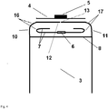
- the cross-bottom bag 1 is closed with wall parts 2 and 3 at one end by means of an inner bar 7 which is connected to side flaps 10, 11 and bottom cover 8, 9, so that no filling material can escape.
- Side flaps 10, 11 and inner bars are folded and glued along folds 16, 17 parallel to the longitudinal direction 14 of the bottom so that a gap between the side edges 12 and 13 of the side flaps remains above the tear strip. Then the cover sheet 4 is attached.
- Inner bar and cover sheet can be mounted independently of each other symmetrically or asymmetrically with respect to the longitudinal axis 14 or the transverse axis 15.
- the cover sheet 4 has the integrated carrying handle 5, which is formed between the cuts 5 '.
- At tear strip 6 can be opened by pulling the bag, wherein the inner bar 7 breaks and cover sheet 4 is detached without tearing.
Landscapes
- Engineering & Computer Science (AREA)
- Mechanical Engineering (AREA)
- Bag Frames (AREA)
Claims (15)
- Sac à fond croisé comportant une poignée de transport (5) intégrée dans une couverture (4) et comportant un verrou intérieur (7) avec une bande de déchirement (6) caractérisé en ce que la bande de déchirement est fixée sur la surface du verrou intérieur indiquant à l'intérieur du sac, le verrou intérieur et la poignée de transport, intégrée dans la couverture, étant dans le fond de support et la couverture étant faite d'une matière antidéchirure et robuste.
- Sac à fond croisé selon la revendication 1, caractérisé en ce que c'est un sac de papier.
- Sac à fond croisé selon l'une des revendications précédentes, caractérisé en ce que c'est un sac de valve.
- Sac à fond croisé selon la revendication précédente caractérisé en ce qu'une couverture est attachée au fond du valve.
- Sac à fond croisé selon la revendication 4, caractérisé en ce que le verrou intérieur comporte un pli au coté transversale indiquant à l' intérieur du sac.
- Sac à fond croisé selon la revendication 1, caractérisé en ce que dans la couverture, il y a deux coupures que forment les bords latéraux de la poignée de transport.
- Sac à fond croisé selon la revendication 1, caractérisé en ce que le verrou intérieur est plié avec les éclisses latérales (10,11) et en ce que les surfaces du verrou intérieur, pliés l'une sur l'autre, sont reliées l'une avec l'autre.
- Sac à fond croisé selon la revendication 7, caractérisé en ce que la couverture est formée du papier renforcé avec de matière plastique.
- Sac à fond croisé selon l'une des revendications précédentes 3 à 5, caractérisé en ce que la couverture est attachée par un adhésif de fécule avec les éclisses latérales et/ou pli latéral.
- Sac à fond croisé selon l'une des revendications précédentes caractérisé en ce que la bande de déchirement et la poignée de transport sont arrangés l'une sur l'autre centralement à la couverture.
- Sac à fond croisé selon l'une des revendications précédentes caractérisé en ce que ce comporte au moins un dispositif de désaération.
- Sac à fond croisé selon l'une des revendications précédentes caractérisé en ce que le sac- en face du fond avec la poignée de transport- a un fond avec une valve et au moins un dispositif de désaération A.
- Sac à fond croisé selon l'une des revendications précédentes caractérisé en ce que la surface de la valve, indiquant à l'extérieur du sac, est pour un part reliée avec le dispositif désaération A, indiquant à l intérieur du sac de telle sorte qu'un part de la surface du dispositif désaération A forme la surface du fond intérieur du sac de valve dans cette région et le dispositif de désaération forme une chambre de désaération le longue du fond pendant que la chambre de désaération est fermé sur le coté de la valve.
- Sac à fond croisé selon l'une des revendications précédentes caractérisé en ce que ce comporte un dispositif de désaération B en forme d'une poche- ouverte au l'intérieur du sac entre le pli du fond et les deux éclisses, formés par les bords latéraux.
- Sac à fond croisé selon l'une des revendications précédentes caractérisé en ce que ce comporte un dispositif de désaération C, comportant une ouverture dans le dispositif de désaération A le longue du fond et une ouverture entre la couverture du fond de valve et l'éclisse latérale sous-jacente.
Priority Applications (1)
| Application Number | Priority Date | Filing Date | Title |
|---|---|---|---|
| PL14179507T PL2905236T3 (pl) | 2014-02-11 | 2014-08-01 | Worek o dnie krzyżowym z uchwytem do noszenia, wykładziną wewnętrzną i paskiem do odrywania |
Applications Claiming Priority (1)
| Application Number | Priority Date | Filing Date | Title |
|---|---|---|---|
| DE202014100593.5U DE202014100593U1 (de) | 2014-02-11 | 2014-02-11 | Kreuzbodensack mit Tragegriff, Innenriegel und Aufreißstreifen |
Publications (2)
| Publication Number | Publication Date |
|---|---|
| EP2905236A1 EP2905236A1 (fr) | 2015-08-12 |
| EP2905236B1 true EP2905236B1 (fr) | 2017-10-04 |
Family
ID=51015422
Family Applications (1)
| Application Number | Title | Priority Date | Filing Date |
|---|---|---|---|
| EP14179507.0A Active EP2905236B1 (fr) | 2014-02-11 | 2014-08-01 | Sac à fond croisé doté d'une poignée de transport, d'un verrou intérieur et de languettes de déchirage |
Country Status (3)
| Country | Link |
|---|---|
| EP (1) | EP2905236B1 (fr) |
| DE (1) | DE202014100593U1 (fr) |
| PL (1) | PL2905236T3 (fr) |
Cited By (1)
| Publication number | Priority date | Publication date | Assignee | Title |
|---|---|---|---|---|
| EP4442583A3 (fr) * | 2020-02-17 | 2025-01-29 | Drylock Technologies NV | Emballage comprenant un sac et une pile d'articles absorbants et son procédé de fabrication |
Families Citing this family (2)
| Publication number | Priority date | Publication date | Assignee | Title |
|---|---|---|---|---|
| DE202018105191U1 (de) * | 2018-09-11 | 2019-12-12 | Dy-Pack Verpackungen Gustav Dyckerhoff Gmbh | Sack für Schüttgut |
| DE102020119749A1 (de) * | 2020-07-27 | 2022-01-27 | Dy-Pack Verpackungen Gustav Dyckerhoff Gmbh | Verpackungsbeutel und Verpackungsverfahren |
Family Cites Families (8)
| Publication number | Priority date | Publication date | Assignee | Title |
|---|---|---|---|---|
| DE4010822A1 (de) | 1990-04-04 | 1991-10-10 | Wilhelmstal Werke Gmbh | Kreuzbodensack |
| DE4021801A1 (de) | 1990-04-23 | 1991-10-24 | Windmoeller & Hoelscher | Sack oder beutel mit im gefuellten zustand rechteckigem boden und angeklebtem griffteil |
| DE10352109A1 (de) * | 2003-11-04 | 2005-06-16 | Korsnäs Wilhelmstal GmbH Papiersackfabriken | Papier- oder Kunststoffsack |
| DE202006006436U1 (de) | 2006-04-21 | 2006-06-22 | Dy-Pack Verpackungen Gustav Dyckerhoff Gmbh | Papiersack mit Deckblattauftrag |
| DE102007015099A1 (de) | 2007-03-29 | 2008-10-02 | Construction Research & Technology Gmbh | Papierventilsack mit Innenriegel |
| DE202009003080U1 (de) | 2009-03-04 | 2009-04-30 | Dy-Pack Verpackungen Gustav Dyckerhoff Gmbh | Papiersack |
| DE102010055777B4 (de) * | 2010-12-23 | 2012-11-22 | Mondi Ag | Sack |
| DE202013102644U1 (de) * | 2013-06-19 | 2013-07-24 | Papiersackfabrik Tenax Gmbh & Co. Kg | Ventilsack mit Entlüftungsvorrichtungen |
-
2014
- 2014-02-11 DE DE202014100593.5U patent/DE202014100593U1/de not_active Expired - Lifetime
- 2014-08-01 PL PL14179507T patent/PL2905236T3/pl unknown
- 2014-08-01 EP EP14179507.0A patent/EP2905236B1/fr active Active
Non-Patent Citations (1)
| Title |
|---|
| None * |
Cited By (1)
| Publication number | Priority date | Publication date | Assignee | Title |
|---|---|---|---|---|
| EP4442583A3 (fr) * | 2020-02-17 | 2025-01-29 | Drylock Technologies NV | Emballage comprenant un sac et une pile d'articles absorbants et son procédé de fabrication |
Also Published As
| Publication number | Publication date |
|---|---|
| DE202014100593U1 (de) | 2014-06-10 |
| EP2905236A1 (fr) | 2015-08-12 |
| PL2905236T3 (pl) | 2018-03-30 |
Similar Documents
| Publication | Publication Date | Title |
|---|---|---|
| DE4007649C1 (fr) | ||
| EP1858769B1 (fr) | Sachet en papier | |
| EP2132103B1 (fr) | Sac à valve en papier doté d'une bande de fermeture | |
| EP0494582A1 (fr) | Emballage sous forme de sachet avec un moyen facilitant l'ouverture | |
| EP2345595B1 (fr) | Sac d'aération doté d'un dispositif d'aération | |
| DE102006029119A1 (de) | Folienbeutel | |
| EP2752371B1 (fr) | Sac doté d'un dispositif de purge d'air | |
| EP2905236B1 (fr) | Sac à fond croisé doté d'une poignée de transport, d'un verrou intérieur et de languettes de déchirage | |
| DE102013008978B4 (de) | Mehrkammerbeutel, Beutelrolle damit, Folienbahn dafür und Verfahren zum Herstellen des Mehrkammerbeutels oder der Beutelrolle | |
| EP1600399A1 (fr) | Sac en plastique pour matériau en vrac | |
| DE1214598B (de) | Behaelter mit fluessigkeitsundurchlaessigem Innenbeutel | |
| EP2050689A1 (fr) | Sac d'emballage | |
| EP0767105A1 (fr) | Sac à valve à fond croisé ventilé | |
| EP2684813B1 (fr) | Sac d'aération doté de dispositifs d'aération | |
| DE102012007407B4 (de) | Sack mit einem Sackboden und Verfahren zum Öffnen eines solchen Sacks | |
| EP2186742A1 (fr) | Sac d'emballage en film, en particulier pour matière de remplissage poudreuse et poussiéreuse | |
| EP3107816B1 (fr) | Sac | |
| DE102012110145A1 (de) | Transportverpackung mit stabilem Boden | |
| EP2687456B1 (fr) | Récipient d'emballage avec fonction d'aération | |
| DE10325175B4 (de) | Verschlusssystem für flexible Verpackungen | |
| DE202011050182U1 (de) | Faltschachtel mit Innenlasche | |
| EP3858755B1 (fr) | Sachet à pliure latérale | |
| EP3812295A1 (fr) | Pochette d'expédition en matière plastique ainsi qu'utilisation de la pochette d'expédition en matière plastique | |
| DE202010008166U1 (de) | Papiersack mit Öffnungsvorrichtung | |
| DE19948191A1 (de) | Beutel aus Kunststoff-Folie |
Legal Events
| Date | Code | Title | Description |
|---|---|---|---|
| PUAI | Public reference made under article 153(3) epc to a published international application that has entered the european phase |
Free format text: ORIGINAL CODE: 0009012 |
|
| AK | Designated contracting states |
Kind code of ref document: A1 Designated state(s): AL AT BE BG CH CY CZ DE DK EE ES FI FR GB GR HR HU IE IS IT LI LT LU LV MC MK MT NL NO PL PT RO RS SE SI SK SM TR |
|
| AX | Request for extension of the european patent |
Extension state: BA ME |
|
| 17P | Request for examination filed |
Effective date: 20160211 |
|
| RBV | Designated contracting states (corrected) |
Designated state(s): AL AT BE BG CH CY CZ DE DK EE ES FI FR GB GR HR HU IE IS IT LI LT LU LV MC MK MT NL NO PL PT RO RS SE SI SK SM TR |
|
| 17Q | First examination report despatched |
Effective date: 20160614 |
|
| GRAP | Despatch of communication of intention to grant a patent |
Free format text: ORIGINAL CODE: EPIDOSNIGR1 |
|
| INTG | Intention to grant announced |
Effective date: 20170613 |
|
| GRAA | (expected) grant |
Free format text: ORIGINAL CODE: 0009210 |
|
| GRAS | Grant fee paid |
Free format text: ORIGINAL CODE: EPIDOSNIGR3 |
|
| AK | Designated contracting states |
Kind code of ref document: B1 Designated state(s): AL AT BE BG CH CY CZ DE DK EE ES FI FR GB GR HR HU IE IS IT LI LT LU LV MC MK MT NL NO PL PT RO RS SE SI SK SM TR |
|
| REG | Reference to a national code |
Ref country code: GB Ref legal event code: FG4D Free format text: NOT ENGLISH |
|
| REG | Reference to a national code |
Ref country code: CH Ref legal event code: EP |
|
| REG | Reference to a national code |
Ref country code: AT Ref legal event code: REF Ref document number: 933780 Country of ref document: AT Kind code of ref document: T Effective date: 20171015 |
|
| REG | Reference to a national code |
Ref country code: IE Ref legal event code: FG4D Free format text: LANGUAGE OF EP DOCUMENT: GERMAN |
|
| REG | Reference to a national code |
Ref country code: DE Ref legal event code: R096 Ref document number: 502014005656 Country of ref document: DE |
|
| REG | Reference to a national code |
Ref country code: NL Ref legal event code: FP |
|
| REG | Reference to a national code |
Ref country code: LT Ref legal event code: MG4D |
|
| PG25 | Lapsed in a contracting state [announced via postgrant information from national office to epo] |
Ref country code: FI Free format text: LAPSE BECAUSE OF FAILURE TO SUBMIT A TRANSLATION OF THE DESCRIPTION OR TO PAY THE FEE WITHIN THE PRESCRIBED TIME-LIMIT Effective date: 20171004 Ref country code: SE Free format text: LAPSE BECAUSE OF FAILURE TO SUBMIT A TRANSLATION OF THE DESCRIPTION OR TO PAY THE FEE WITHIN THE PRESCRIBED TIME-LIMIT Effective date: 20171004 Ref country code: ES Free format text: LAPSE BECAUSE OF FAILURE TO SUBMIT A TRANSLATION OF THE DESCRIPTION OR TO PAY THE FEE WITHIN THE PRESCRIBED TIME-LIMIT Effective date: 20171004 Ref country code: LT Free format text: LAPSE BECAUSE OF FAILURE TO SUBMIT A TRANSLATION OF THE DESCRIPTION OR TO PAY THE FEE WITHIN THE PRESCRIBED TIME-LIMIT Effective date: 20171004 Ref country code: NO Free format text: LAPSE BECAUSE OF FAILURE TO SUBMIT A TRANSLATION OF THE DESCRIPTION OR TO PAY THE FEE WITHIN THE PRESCRIBED TIME-LIMIT Effective date: 20180104 |
|
| PG25 | Lapsed in a contracting state [announced via postgrant information from national office to epo] |
Ref country code: GR Free format text: LAPSE BECAUSE OF FAILURE TO SUBMIT A TRANSLATION OF THE DESCRIPTION OR TO PAY THE FEE WITHIN THE PRESCRIBED TIME-LIMIT Effective date: 20180105 Ref country code: BG Free format text: LAPSE BECAUSE OF FAILURE TO SUBMIT A TRANSLATION OF THE DESCRIPTION OR TO PAY THE FEE WITHIN THE PRESCRIBED TIME-LIMIT Effective date: 20180104 Ref country code: IS Free format text: LAPSE BECAUSE OF FAILURE TO SUBMIT A TRANSLATION OF THE DESCRIPTION OR TO PAY THE FEE WITHIN THE PRESCRIBED TIME-LIMIT Effective date: 20180204 Ref country code: RS Free format text: LAPSE BECAUSE OF FAILURE TO SUBMIT A TRANSLATION OF THE DESCRIPTION OR TO PAY THE FEE WITHIN THE PRESCRIBED TIME-LIMIT Effective date: 20171004 Ref country code: LV Free format text: LAPSE BECAUSE OF FAILURE TO SUBMIT A TRANSLATION OF THE DESCRIPTION OR TO PAY THE FEE WITHIN THE PRESCRIBED TIME-LIMIT Effective date: 20171004 Ref country code: HR Free format text: LAPSE BECAUSE OF FAILURE TO SUBMIT A TRANSLATION OF THE DESCRIPTION OR TO PAY THE FEE WITHIN THE PRESCRIBED TIME-LIMIT Effective date: 20171004 |
|
| REG | Reference to a national code |
Ref country code: DE Ref legal event code: R097 Ref document number: 502014005656 Country of ref document: DE |
|
| PG25 | Lapsed in a contracting state [announced via postgrant information from national office to epo] |
Ref country code: CZ Free format text: LAPSE BECAUSE OF FAILURE TO SUBMIT A TRANSLATION OF THE DESCRIPTION OR TO PAY THE FEE WITHIN THE PRESCRIBED TIME-LIMIT Effective date: 20171004 Ref country code: SK Free format text: LAPSE BECAUSE OF FAILURE TO SUBMIT A TRANSLATION OF THE DESCRIPTION OR TO PAY THE FEE WITHIN THE PRESCRIBED TIME-LIMIT Effective date: 20171004 Ref country code: DK Free format text: LAPSE BECAUSE OF FAILURE TO SUBMIT A TRANSLATION OF THE DESCRIPTION OR TO PAY THE FEE WITHIN THE PRESCRIBED TIME-LIMIT Effective date: 20171004 Ref country code: EE Free format text: LAPSE BECAUSE OF FAILURE TO SUBMIT A TRANSLATION OF THE DESCRIPTION OR TO PAY THE FEE WITHIN THE PRESCRIBED TIME-LIMIT Effective date: 20171004 |
|
| PLBE | No opposition filed within time limit |
Free format text: ORIGINAL CODE: 0009261 |
|
| STAA | Information on the status of an ep patent application or granted ep patent |
Free format text: STATUS: NO OPPOSITION FILED WITHIN TIME LIMIT |
|
| REG | Reference to a national code |
Ref country code: FR Ref legal event code: PLFP Year of fee payment: 5 |
|
| PG25 | Lapsed in a contracting state [announced via postgrant information from national office to epo] |
Ref country code: SM Free format text: LAPSE BECAUSE OF FAILURE TO SUBMIT A TRANSLATION OF THE DESCRIPTION OR TO PAY THE FEE WITHIN THE PRESCRIBED TIME-LIMIT Effective date: 20171004 Ref country code: RO Free format text: LAPSE BECAUSE OF FAILURE TO SUBMIT A TRANSLATION OF THE DESCRIPTION OR TO PAY THE FEE WITHIN THE PRESCRIBED TIME-LIMIT Effective date: 20171004 |
|
| 26N | No opposition filed |
Effective date: 20180705 |
|
| PG25 | Lapsed in a contracting state [announced via postgrant information from national office to epo] |
Ref country code: MT Free format text: LAPSE BECAUSE OF FAILURE TO SUBMIT A TRANSLATION OF THE DESCRIPTION OR TO PAY THE FEE WITHIN THE PRESCRIBED TIME-LIMIT Effective date: 20171004 |
|
| PG25 | Lapsed in a contracting state [announced via postgrant information from national office to epo] |
Ref country code: SI Free format text: LAPSE BECAUSE OF FAILURE TO SUBMIT A TRANSLATION OF THE DESCRIPTION OR TO PAY THE FEE WITHIN THE PRESCRIBED TIME-LIMIT Effective date: 20171004 |
|
| REG | Reference to a national code |
Ref country code: DE Ref legal event code: R082 Ref document number: 502014005656 Country of ref document: DE Representative=s name: MEISSNER BOLTE PATENTANWAELTE RECHTSANWAELTE P, DE |
|
| PG25 | Lapsed in a contracting state [announced via postgrant information from national office to epo] |
Ref country code: MC Free format text: LAPSE BECAUSE OF FAILURE TO SUBMIT A TRANSLATION OF THE DESCRIPTION OR TO PAY THE FEE WITHIN THE PRESCRIBED TIME-LIMIT Effective date: 20171004 |
|
| REG | Reference to a national code |
Ref country code: CH Ref legal event code: PL |
|
| GBPC | Gb: european patent ceased through non-payment of renewal fee |
Effective date: 20180801 |
|
| PG25 | Lapsed in a contracting state [announced via postgrant information from national office to epo] |
Ref country code: LI Free format text: LAPSE BECAUSE OF NON-PAYMENT OF DUE FEES Effective date: 20180831 Ref country code: LU Free format text: LAPSE BECAUSE OF NON-PAYMENT OF DUE FEES Effective date: 20180801 Ref country code: CH Free format text: LAPSE BECAUSE OF NON-PAYMENT OF DUE FEES Effective date: 20180831 |
|
| REG | Reference to a national code |
Ref country code: IE Ref legal event code: MM4A |
|
| PG25 | Lapsed in a contracting state [announced via postgrant information from national office to epo] |
Ref country code: IE Free format text: LAPSE BECAUSE OF NON-PAYMENT OF DUE FEES Effective date: 20180801 |
|
| PG25 | Lapsed in a contracting state [announced via postgrant information from national office to epo] |
Ref country code: GB Free format text: LAPSE BECAUSE OF NON-PAYMENT OF DUE FEES Effective date: 20180801 |
|
| PG25 | Lapsed in a contracting state [announced via postgrant information from national office to epo] |
Ref country code: TR Free format text: LAPSE BECAUSE OF FAILURE TO SUBMIT A TRANSLATION OF THE DESCRIPTION OR TO PAY THE FEE WITHIN THE PRESCRIBED TIME-LIMIT Effective date: 20171004 |
|
| PG25 | Lapsed in a contracting state [announced via postgrant information from national office to epo] |
Ref country code: PT Free format text: LAPSE BECAUSE OF FAILURE TO SUBMIT A TRANSLATION OF THE DESCRIPTION OR TO PAY THE FEE WITHIN THE PRESCRIBED TIME-LIMIT Effective date: 20171004 |
|
| REG | Reference to a national code |
Ref country code: DE Ref legal event code: R082 Ref document number: 502014005656 Country of ref document: DE Representative=s name: MEISSNER BOLTE PATENTANWAELTE RECHTSANWAELTE P, DE |
|
| PG25 | Lapsed in a contracting state [announced via postgrant information from national office to epo] |
Ref country code: HU Free format text: LAPSE BECAUSE OF FAILURE TO SUBMIT A TRANSLATION OF THE DESCRIPTION OR TO PAY THE FEE WITHIN THE PRESCRIBED TIME-LIMIT; INVALID AB INITIO Effective date: 20140801 Ref country code: CY Free format text: LAPSE BECAUSE OF FAILURE TO SUBMIT A TRANSLATION OF THE DESCRIPTION OR TO PAY THE FEE WITHIN THE PRESCRIBED TIME-LIMIT Effective date: 20171004 Ref country code: MK Free format text: LAPSE BECAUSE OF NON-PAYMENT OF DUE FEES Effective date: 20171004 |
|
| PG25 | Lapsed in a contracting state [announced via postgrant information from national office to epo] |
Ref country code: AL Free format text: LAPSE BECAUSE OF FAILURE TO SUBMIT A TRANSLATION OF THE DESCRIPTION OR TO PAY THE FEE WITHIN THE PRESCRIBED TIME-LIMIT Effective date: 20171004 |
|
| REG | Reference to a national code |
Ref country code: AT Ref legal event code: MM01 Ref document number: 933780 Country of ref document: AT Kind code of ref document: T Effective date: 20190801 |
|
| PG25 | Lapsed in a contracting state [announced via postgrant information from national office to epo] |
Ref country code: AT Free format text: LAPSE BECAUSE OF NON-PAYMENT OF DUE FEES Effective date: 20190801 |
|
| P01 | Opt-out of the competence of the unified patent court (upc) registered |
Effective date: 20230601 |
|
| PGFP | Annual fee paid to national office [announced via postgrant information from national office to epo] |
Ref country code: NL Payment date: 20250825 Year of fee payment: 12 |
|
| PGFP | Annual fee paid to national office [announced via postgrant information from national office to epo] |
Ref country code: DE Payment date: 20250828 Year of fee payment: 12 |
|
| PGFP | Annual fee paid to national office [announced via postgrant information from national office to epo] |
Ref country code: PL Payment date: 20250708 Year of fee payment: 12 Ref country code: IT Payment date: 20250825 Year of fee payment: 12 |
|
| PGFP | Annual fee paid to national office [announced via postgrant information from national office to epo] |
Ref country code: BE Payment date: 20250825 Year of fee payment: 12 |
|
| PGFP | Annual fee paid to national office [announced via postgrant information from national office to epo] |
Ref country code: FR Payment date: 20250825 Year of fee payment: 12 |