EP2905355A1 - Inline-beschichtungsvorrichtung, inline-beschichtungsverfahren und separator - Google Patents
Inline-beschichtungsvorrichtung, inline-beschichtungsverfahren und separator Download PDFInfo
- Publication number
- EP2905355A1 EP2905355A1 EP13843240.6A EP13843240A EP2905355A1 EP 2905355 A1 EP2905355 A1 EP 2905355A1 EP 13843240 A EP13843240 A EP 13843240A EP 2905355 A1 EP2905355 A1 EP 2905355A1
- Authority
- EP
- European Patent Office
- Prior art keywords
- workpiece
- coating
- section
- faces
- workpieces
- Prior art date
- Legal status (The legal status is an assumption and is not a legal conclusion. Google has not performed a legal analysis and makes no representation as to the accuracy of the status listed.)
- Granted
Links
- 238000000576 coating method Methods 0.000 title claims abstract description 197
- 239000011248 coating agent Substances 0.000 title claims abstract description 173
- 239000000463 material Substances 0.000 claims abstract description 89
- 239000002245 particle Substances 0.000 claims abstract description 7
- 230000032258 transport Effects 0.000 claims description 62
- 239000011247 coating layer Substances 0.000 claims description 26
- 238000005520 cutting process Methods 0.000 claims description 4
- 238000011144 upstream manufacturing Methods 0.000 claims description 4
- 238000004519 manufacturing process Methods 0.000 abstract description 12
- 239000012212 insulator Substances 0.000 description 18
- 230000000694 effects Effects 0.000 description 10
- 239000010410 layer Substances 0.000 description 8
- 238000000034 method Methods 0.000 description 8
- 239000007789 gas Substances 0.000 description 5
- 229910052756 noble gas Inorganic materials 0.000 description 5
- 150000002500 ions Chemical class 0.000 description 4
- VYZAMTAEIAYCRO-UHFFFAOYSA-N Chromium Chemical compound [Cr] VYZAMTAEIAYCRO-UHFFFAOYSA-N 0.000 description 3
- 238000007733 ion plating Methods 0.000 description 3
- 229910052751 metal Inorganic materials 0.000 description 3
- 239000002184 metal Substances 0.000 description 3
- 239000011347 resin Substances 0.000 description 3
- 229920005989 resin Polymers 0.000 description 3
- 238000004544 sputter deposition Methods 0.000 description 3
- 239000010936 titanium Substances 0.000 description 3
- XKRFYHLGVUSROY-UHFFFAOYSA-N Argon Chemical compound [Ar] XKRFYHLGVUSROY-UHFFFAOYSA-N 0.000 description 2
- OKTJSMMVPCPJKN-UHFFFAOYSA-N Carbon Chemical compound [C] OKTJSMMVPCPJKN-UHFFFAOYSA-N 0.000 description 2
- XEEYBQQBJWHFJM-UHFFFAOYSA-N Iron Chemical compound [Fe] XEEYBQQBJWHFJM-UHFFFAOYSA-N 0.000 description 2
- RTAQQCXQSZGOHL-UHFFFAOYSA-N Titanium Chemical compound [Ti] RTAQQCXQSZGOHL-UHFFFAOYSA-N 0.000 description 2
- 229910052799 carbon Inorganic materials 0.000 description 2
- 230000002950 deficient Effects 0.000 description 2
- 239000000446 fuel Substances 0.000 description 2
- 238000012423 maintenance Methods 0.000 description 2
- 239000010955 niobium Substances 0.000 description 2
- 229910052719 titanium Inorganic materials 0.000 description 2
- 229910000640 Fe alloy Inorganic materials 0.000 description 1
- ZOKXTWBITQBERF-UHFFFAOYSA-N Molybdenum Chemical compound [Mo] ZOKXTWBITQBERF-UHFFFAOYSA-N 0.000 description 1
- 229910045601 alloy Inorganic materials 0.000 description 1
- 239000000956 alloy Substances 0.000 description 1
- 229910052782 aluminium Inorganic materials 0.000 description 1
- XAGFODPZIPBFFR-UHFFFAOYSA-N aluminium Chemical compound [Al] XAGFODPZIPBFFR-UHFFFAOYSA-N 0.000 description 1
- 229910052786 argon Inorganic materials 0.000 description 1
- 238000005452 bending Methods 0.000 description 1
- 238000005422 blasting Methods 0.000 description 1
- 238000005260 corrosion Methods 0.000 description 1
- 230000007797 corrosion Effects 0.000 description 1
- 238000010894 electron beam technology Methods 0.000 description 1
- 229910052735 hafnium Inorganic materials 0.000 description 1
- VBJZVLUMGGDVMO-UHFFFAOYSA-N hafnium atom Chemical compound [Hf] VBJZVLUMGGDVMO-UHFFFAOYSA-N 0.000 description 1
- 239000011261 inert gas Substances 0.000 description 1
- 229910052742 iron Inorganic materials 0.000 description 1
- 150000001247 metal acetylides Chemical class 0.000 description 1
- 229910052750 molybdenum Inorganic materials 0.000 description 1
- 239000011733 molybdenum Substances 0.000 description 1
- 229910052758 niobium Inorganic materials 0.000 description 1
- GUCVJGMIXFAOAE-UHFFFAOYSA-N niobium atom Chemical compound [Nb] GUCVJGMIXFAOAE-UHFFFAOYSA-N 0.000 description 1
- 150000004767 nitrides Chemical class 0.000 description 1
- 239000005518 polymer electrolyte Substances 0.000 description 1
- 238000005096 rolling process Methods 0.000 description 1
- 238000000638 solvent extraction Methods 0.000 description 1
- 239000000758 substrate Substances 0.000 description 1
- WFKWXMTUELFFGS-UHFFFAOYSA-N tungsten Chemical compound [W] WFKWXMTUELFFGS-UHFFFAOYSA-N 0.000 description 1
- 229910052721 tungsten Inorganic materials 0.000 description 1
- 239000010937 tungsten Substances 0.000 description 1
Images




Classifications
-
- C—CHEMISTRY; METALLURGY
- C23—COATING METALLIC MATERIAL; COATING MATERIAL WITH METALLIC MATERIAL; CHEMICAL SURFACE TREATMENT; DIFFUSION TREATMENT OF METALLIC MATERIAL; COATING BY VACUUM EVAPORATION, BY SPUTTERING, BY ION IMPLANTATION OR BY CHEMICAL VAPOUR DEPOSITION, IN GENERAL; INHIBITING CORROSION OF METALLIC MATERIAL OR INCRUSTATION IN GENERAL
- C23C—COATING METALLIC MATERIAL; COATING MATERIAL WITH METALLIC MATERIAL; SURFACE TREATMENT OF METALLIC MATERIAL BY DIFFUSION INTO THE SURFACE, BY CHEMICAL CONVERSION OR SUBSTITUTION; COATING BY VACUUM EVAPORATION, BY SPUTTERING, BY ION IMPLANTATION OR BY CHEMICAL VAPOUR DEPOSITION, IN GENERAL
- C23C14/00—Coating by vacuum evaporation, by sputtering or by ion implantation of the coating forming material
- C23C14/22—Coating by vacuum evaporation, by sputtering or by ion implantation of the coating forming material characterised by the process of coating
- C23C14/24—Vacuum evaporation
- C23C14/32—Vacuum evaporation by explosion; by evaporation and subsequent ionisation of the vapours, e.g. ion-plating
-
- C—CHEMISTRY; METALLURGY
- C23—COATING METALLIC MATERIAL; COATING MATERIAL WITH METALLIC MATERIAL; CHEMICAL SURFACE TREATMENT; DIFFUSION TREATMENT OF METALLIC MATERIAL; COATING BY VACUUM EVAPORATION, BY SPUTTERING, BY ION IMPLANTATION OR BY CHEMICAL VAPOUR DEPOSITION, IN GENERAL; INHIBITING CORROSION OF METALLIC MATERIAL OR INCRUSTATION IN GENERAL
- C23C—COATING METALLIC MATERIAL; COATING MATERIAL WITH METALLIC MATERIAL; SURFACE TREATMENT OF METALLIC MATERIAL BY DIFFUSION INTO THE SURFACE, BY CHEMICAL CONVERSION OR SUBSTITUTION; COATING BY VACUUM EVAPORATION, BY SPUTTERING, BY ION IMPLANTATION OR BY CHEMICAL VAPOUR DEPOSITION, IN GENERAL
- C23C14/00—Coating by vacuum evaporation, by sputtering or by ion implantation of the coating forming material
- C23C14/22—Coating by vacuum evaporation, by sputtering or by ion implantation of the coating forming material characterised by the process of coating
- C23C14/34—Sputtering
- C23C14/3435—Applying energy to the substrate during sputtering
- C23C14/345—Applying energy to the substrate during sputtering using substrate bias
-
- C—CHEMISTRY; METALLURGY
- C23—COATING METALLIC MATERIAL; COATING MATERIAL WITH METALLIC MATERIAL; CHEMICAL SURFACE TREATMENT; DIFFUSION TREATMENT OF METALLIC MATERIAL; COATING BY VACUUM EVAPORATION, BY SPUTTERING, BY ION IMPLANTATION OR BY CHEMICAL VAPOUR DEPOSITION, IN GENERAL; INHIBITING CORROSION OF METALLIC MATERIAL OR INCRUSTATION IN GENERAL
- C23C—COATING METALLIC MATERIAL; COATING MATERIAL WITH METALLIC MATERIAL; SURFACE TREATMENT OF METALLIC MATERIAL BY DIFFUSION INTO THE SURFACE, BY CHEMICAL CONVERSION OR SUBSTITUTION; COATING BY VACUUM EVAPORATION, BY SPUTTERING, BY ION IMPLANTATION OR BY CHEMICAL VAPOUR DEPOSITION, IN GENERAL
- C23C14/00—Coating by vacuum evaporation, by sputtering or by ion implantation of the coating forming material
- C23C14/22—Coating by vacuum evaporation, by sputtering or by ion implantation of the coating forming material characterised by the process of coating
- C23C14/34—Sputtering
- C23C14/3464—Sputtering using more than one target
-
- C—CHEMISTRY; METALLURGY
- C23—COATING METALLIC MATERIAL; COATING MATERIAL WITH METALLIC MATERIAL; CHEMICAL SURFACE TREATMENT; DIFFUSION TREATMENT OF METALLIC MATERIAL; COATING BY VACUUM EVAPORATION, BY SPUTTERING, BY ION IMPLANTATION OR BY CHEMICAL VAPOUR DEPOSITION, IN GENERAL; INHIBITING CORROSION OF METALLIC MATERIAL OR INCRUSTATION IN GENERAL
- C23C—COATING METALLIC MATERIAL; COATING MATERIAL WITH METALLIC MATERIAL; SURFACE TREATMENT OF METALLIC MATERIAL BY DIFFUSION INTO THE SURFACE, BY CHEMICAL CONVERSION OR SUBSTITUTION; COATING BY VACUUM EVAPORATION, BY SPUTTERING, BY ION IMPLANTATION OR BY CHEMICAL VAPOUR DEPOSITION, IN GENERAL
- C23C14/00—Coating by vacuum evaporation, by sputtering or by ion implantation of the coating forming material
- C23C14/22—Coating by vacuum evaporation, by sputtering or by ion implantation of the coating forming material characterised by the process of coating
- C23C14/56—Apparatus specially adapted for continuous coating; Arrangements for maintaining the vacuum, e.g. vacuum locks
- C23C14/568—Transferring the substrates through a series of coating stations
-
- H—ELECTRICITY
- H01—ELECTRIC ELEMENTS
- H01M—PROCESSES OR MEANS, e.g. BATTERIES, FOR THE DIRECT CONVERSION OF CHEMICAL ENERGY INTO ELECTRICAL ENERGY
- H01M8/00—Fuel cells; Manufacture thereof
- H01M8/02—Details
- H01M8/0202—Collectors; Separators, e.g. bipolar separators; Interconnectors
- H01M8/0204—Non-porous and characterised by the material
- H01M8/0223—Composites
- H01M8/0228—Composites in the form of layered or coated products
-
- H—ELECTRICITY
- H01—ELECTRIC ELEMENTS
- H01M—PROCESSES OR MEANS, e.g. BATTERIES, FOR THE DIRECT CONVERSION OF CHEMICAL ENERGY INTO ELECTRICAL ENERGY
- H01M8/00—Fuel cells; Manufacture thereof
- H01M8/02—Details
- H01M8/0202—Collectors; Separators, e.g. bipolar separators; Interconnectors
- H01M8/023—Porous and characterised by the material
- H01M8/0241—Composites
- H01M8/0245—Composites in the form of layered or coated products
-
- Y—GENERAL TAGGING OF NEW TECHNOLOGICAL DEVELOPMENTS; GENERAL TAGGING OF CROSS-SECTIONAL TECHNOLOGIES SPANNING OVER SEVERAL SECTIONS OF THE IPC; TECHNICAL SUBJECTS COVERED BY FORMER USPC CROSS-REFERENCE ART COLLECTIONS [XRACs] AND DIGESTS
- Y02—TECHNOLOGIES OR APPLICATIONS FOR MITIGATION OR ADAPTATION AGAINST CLIMATE CHANGE
- Y02E—REDUCTION OF GREENHOUSE GAS [GHG] EMISSIONS, RELATED TO ENERGY GENERATION, TRANSMISSION OR DISTRIBUTION
- Y02E60/00—Enabling technologies; Technologies with a potential or indirect contribution to GHG emissions mitigation
- Y02E60/30—Hydrogen technology
- Y02E60/50—Fuel cells
-
- Y—GENERAL TAGGING OF NEW TECHNOLOGICAL DEVELOPMENTS; GENERAL TAGGING OF CROSS-SECTIONAL TECHNOLOGIES SPANNING OVER SEVERAL SECTIONS OF THE IPC; TECHNICAL SUBJECTS COVERED BY FORMER USPC CROSS-REFERENCE ART COLLECTIONS [XRACs] AND DIGESTS
- Y02—TECHNOLOGIES OR APPLICATIONS FOR MITIGATION OR ADAPTATION AGAINST CLIMATE CHANGE
- Y02P—CLIMATE CHANGE MITIGATION TECHNOLOGIES IN THE PRODUCTION OR PROCESSING OF GOODS
- Y02P70/00—Climate change mitigation technologies in the production process for final industrial or consumer products
- Y02P70/50—Manufacturing or production processes characterised by the final manufactured product
Definitions
- the present invention relates to an in-line coating device, an in-line coating method, and a separator.
- Patent Literature 1 the inventors properly adjust the bias voltage to form a coating layer excellent in conduction and corrosion resistance on the surface of a fuel-cell separator.
- Patent Literature 1 Japanese Patent Application Publication No. 2010-272490
- Coating of workpieces with the bias voltage adjusted may be carried out in a batch system, but the inventors particularly examined in-line systems to improve the mass production.
- the invention was made as a result of the examination, and an object of the present invention is to provide an in-line coating device and an in-line coating method which are excellent in mass production and are capable of applying an appropriate bias voltage to workpieces.
- An in-line coating device to achieve the aforementioned object includes: a coating section configured to perform coating on a workpiece; and a transport section configured to transport a plurality of the workpieces in the coating section.
- the coating section is provided with a plurality of coating materials which are aligned.
- the transport section transports the workpieces such that the workpieces face the plurality of coating materials.
- the in-line coating device includes a voltage applying section configured to, when the workpiece is transported and faces each coating material, apply to the workpiece, a bias voltage to attract particles emitted from the coating material toward the workpiece.
- the bias voltages applied to the workpiece by the voltage applying section when the workpiece faces one of the coating materials can be different from that applied when the workpiece faces another one of the coating material.
- An in-line coating method to achieve the aforementioned object includes a coating step of transporting a plurality of workpieces such that the workpieces face a plurality of coating materials which are aligned while applying a bias voltage to the workpiece to attract particles emitted from each coating material toward the workpiece for coating when the workpiece faces the coating material.
- the bias voltage applied when the workpiece faces one of the coating materials is different from the bias voltage applied when the workpiece faces another one of the coating materials.
- a separator to achieve the aforementioned object includes: a thin plate-shaped base material having a rectangular shape; and a coating layer formed on the base material.
- One end face constituting a side of a periphery of the rectangular shape has a different characteristic from that of end faces constituting the other sides thereof.
- the in-line coating device and method having the aforementioned configurations continuously perform coating on the plurality of workpieces by transporting the plurality of workpieces such that the workpieces face the plural coating materials and therefore provide excellent mass production. Moreover, the in-line coating device and method having the aforementioned configurations can apply different bias voltages to each workpiece when the workpiece faces different coating materials. It is therefore possible to apply appropriate bias voltages corresponding to the coating materials.
- the separator having the aforementioned configuration is formed by transporting the plural thin plate-shaped base materials as the workpieces with the ends hooked on the linear member for coating such that the base materials are hung and arranged in the longitudinal direction of the linear member and removing the ends of the base materials hooked on the linear member.
- the linear member constituting the transport unit is covered with the ends of the base materials as the workpieces. This can prevent the coating materials from adhering to the linear member, reducing the trouble of maintenance. Accordingly, the mass production thereof is excellent.
- the ends of the base materials are hooked on the linear member, it is possible to apply appropriate bias voltages corresponding to the respective coating materials to the transported base materials through the ends of the based materials.
- an in-line coating device 10 of a first embodiment includes a belt conveyor 13 (transport section) capable of conveying plural workpieces W.
- the in-line coating device 10 includes: an oxide film removing section 11 in which oxide film on the surface of each workpiece W is removed by bombardment; and a coating section 12 in which each workpiece W is coated.
- the in-line coating device 10 includes a voltage applying section 14 configured to apply bias voltage to each workpiece W at the processes of bombardment and coating.
- Each workpiece W is a thin plate-shaped metallic base material.
- the workpieces W are subjected to coating and other processing to be formed into separators used in a fuel cell.
- the belt conveyor 13 includes: plural conducting portions 130 provided along the transport direction of the workpieces W so as to be spaced from one another; and insulating portions 131 provided between the conducting portions 130.
- the conducting portions 130 and insulating portions 131 constitute a belt of the belt conveyor 13.
- the conducting portions 130 are made of metal, for example.
- the insulating portions 131 are made of resin, for example.
- the belt conveyor 13 transports the workpieces W placed on the respective conducting portions 130. The workpieces W are in contact with the conducting portions 130 for electric connection therebetween.
- the oxide film removing section 11 includes: a chamber 110 in which a part of the belt conveyor 13 is placed; and an electrode 111 arranged facing each workpiece W.
- the chamber 110 communicates with a vacuum pump configured to exhaust the chamber 110 and a noble gas introducing portion configured to introduce noble gas into the chamber 110.
- the oxide film removing section 11 is provided upstream of the coating section 12 in the transport direction of the workpieces W.
- the coating section 12 includes a chamber 120 in which a part of the belt conveyor 13 is placed.
- the chamber 120 communicates with a vacuum pump configured to exhaust the chamber 120 and a noble gas introducing portion configured to introduce noble gas into the chamber 120.
- the chambers 110 and 120 are formed by partitioning a chamber capable of accommodating the entire belt conveyor 13.
- the noble gas introduced to the oxide film removing section 11 and coating section 12 is heavy inert gas such as argon, for example.
- the coating section 12 is provided with four targets 121, 122, 123, and 124 (coating materials) placed along the transport direction of the workpieces W so as to face the individual workpieces W.
- the number of targets is not limited to four.
- the targets 121 and 122 are made of chrome, for example, and the targets 123 and 124 are made of carbon, for example.
- the materials constituting the targets are not limited to these materials.
- a load lock chamber 15 accommodating the workpieces W is provided next to the chamber 110 upstream in the transport direction of the workpieces W.
- the plural workpieces W are accommodated in a box 150 provided within the load lock chamber 15.
- an industrial robot takes the workpieces W out of the box 150 and places the same on the respective conducting portions 130 of the belt conveyor 13, for example.
- the load lock chamber 15 communicates with a vacuum pump configured to exhaust the load lock chamber 15.
- a load lock chamber 16 accommodating the workpieces W is provided next to the chamber 120 downstream in the transport direction of the workpieces W.
- the coated workpieces W are transported by the belt conveyor 13 and are accommodated in a box 160 provided within the load lock chamber 16.
- the load lock chamber 16 communicates with a vacuum pump configured to exhaust the load lock chamber 16.
- a voltage applying section 14 includes power supplies 140, 141, 142, 143, and 144 which are configured to generate bias voltages.
- the bias voltages generated by the power supplies 140 to 144 are different from one another.
- the voltage applying section 14 includes a brush 145 which comes into sliding contact with the belt of the belt conveyor 13 at the position opposite to the electrode 111.
- the power supply 140 and brush 145 are electrically connected.
- the power supply 140 and electrode 111 are electrically connected.
- the voltage applying section 14 includes a brush 146 which comes into sliding contact with the belt of the belt conveyor 13 at the position opposite to the target 121.
- the power supply 141 and brush 146 are electrically connected.
- the power supply 141 and target 121 are electrically connected.
- the voltage applying section 14 includes a brush 147 which comes into sliding contact with the belt of the belt conveyor 13 at the position opposite to the target 122.
- the power supply 142 and brush 147 are electrically connected.
- the power supply 142 and target 122 are electrically connected.
- the voltage applying section 14 includes a brush 148 which comes into sliding contact with the belt of the belt conveyor 13 at the position opposite to the target 123.
- the power supply 143 and brush 148 are electrically connected.
- the power supply 143 and target 123 are electrically connected.
- the voltage applying section 14 includes a brush 149 which comes into sliding contact with the belt of the belt conveyor 13 at the position opposite to the target 124.
- the power supply 144 and brush 149 are electrically connected.
- the power supply 144 and target 124 are electrically connected.
- Each of the brushes 145 to 149 alternately comes into contact with the conducting portions 130 and the insulating portions 131 as the workpieces W are transported by the belt conveyor 13.
- the in-line coating method of the first embodiment includes: an oxide film removing step of removing oxide film on the surface of each workpiece W by bombardment; and a coating step of coating the workpiece W by sputtering after the oxide film removing step.
- the workpiece W and power supply 140 are electrically connected through the conducting portion 130, and the bias voltage generated by the power supply 140 is thereby applied to the workpiece W.
- the bias voltage generated by the power supply 140 is larger than the bias voltages generated by the power supplies 141 to 144.
- the bombardment may be performed on the workpiece W when the workpiece W faces the electrode 111 and is temporarily stopped.
- the mass production can be improved when bombardment is performed on the workpiece W while the workpiece W is transported without being stopped.
- the conducting portion 130 moves with the workpiece W and comes into contact with the brush 146 and the workpiece W faces the target 121, the workpiece W is subjected to coating.
- the bias voltage generated by the power supply 141 is applied to the workpiece W.
- the bias voltage generated by the power supply 141 is applied to the workpiece W, gas between the workpiece W and target 121 is ionized by the potential difference therebetween, and the gas ions are attracted by the target 121 to collide with the target 121.
- the material constituting the target 121 is ejected in the form of atoms or molecules.
- the ejected material constituting the target 121 in the form of atoms or molecules is attracted to the workpiece W to which the bias voltage is applied, so that the workpiece W is coated.
- the conducting portion 130 moves with the workpiece W and comes into contact with the brush 147 and the workpiece W faces the target 122, the workpiece W is subjected to coating.
- the conducting portion 130 moves apart from the brush 147, the coating is stopped.
- the conducting portion 130 moves with the workpiece W and comes into contact with the brush 148 and the workpiece W faces the target 123, the workpiece W is subjected to coating.
- the conducting portion 130 moves apart from the brush 148, the coating is stopped.
- the conducting portion 130 moves with the workpiece W and comes into contact with the brush 149 and the workpiece W faces the target 124, the workpiece W is subjected to coating.
- the conducting portion 130 moves apart from the brush 149, the coating is stopped.
- the workpiece W may be temporarily stopped for coating each time that the workpiece W faces the target 121, 122, 123, or 124.
- the mass production can be improved when coating is performed while the workpiece W is transported without being stopped.
- the coating layers formed on the workpiece W have different properties depending on the bias voltages of the power supplies 141 to 144. Even when the targets 121 and 122 are made of a same material, chrome, for example, the formed coating layers have different properties because of the difference between the bias voltages applied. The properties of each coating layer formed are varied because the crystalline structure of the formed coating layer depends on the bias voltage applied.
- the bias voltages of the power supplies 141 to 144 are set based on the desired properties given to the respective coating layers.
- the bias voltage generated by the power supply 141 for example, is applied to form part of the coating layers in contact with the surface of the workpiece W. Accordingly, in order to reduce the electrical resistance between the coating layer and workpiece W, the bias voltage generated by the power supply 141 is set so that the formed coating layer has high conductivity.
- the plural workpieces W are transported such that the plural workpieces W face the plural targets 121 to 124 for successively perform coating of the plural workpieces W.
- the in-line coating device 10 and in-line coating method of the first embodiment therefore provide high mass production.
- the bias voltage applied to the workpiece W at the process of bombardment of each workpiece W can be different from those applied when the workpiece W faces the targets 121 to 124. It is therefore possible to apply bias voltage appropriate for bombardment. By applying the bias voltage appropriate for bombardment, the oxide film on the surface of the workpiece W is surely removed.
- the application of bias voltages and the stop of the same are switched by electrically connecting the workpiece W and voltage applying section 14 through the conducting portion 130 and disconnecting the electrical connection between the workpiece W and voltage applying section 14 between the conducting portions 130, the connection and disconnection being implemented as the workpiece W is transported. Accordingly, the in-line coating device 10 and in-line coating method of the first embodiment can apply the bias voltages and stop the application of the bias voltages while transporting the workpiece W without stopping the same and therefore provide high mass production.
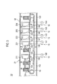
- an in-line coating device 20 of a second embodiment includes electrodes 211 and targets 221, 222, 223, and 224, which are arranged in a different manner from that of the first embodiment. Moreover, the second embodiment is different from the first embodiment in terms of the position of each workpiece W placed on the belt conveyor 13. The second embodiment is the substantially same as the first embodiment other than the above-described matters. In Figs. 2 and 3 , the same components as those of the first embodiment are given the same reference numerals, and an overlapping description is omitted.
- electrodes 211 are arranged on both sides of each workpiece W in the direction that intersects the transport direction of the workpieces W.
- the pairs of targets 221 to 224 are each arranged on both sides of the workpieces W in the direction that intersects the transport direction of the workpieces W.
- the materials constituting the targets 221 to 224 are the same as the materials constituting the targets 121 to 124 of the first embodiment, respectively.
- Each workpiece W is transported, standing such that the both surfaces thereof in the thickness direction face the electrodes 211 or targets 221 to 224.
- the jigs 23 are conductive.
- the jigs 23 electrically connect the respective workpieces W and conducting portions 130 of the belt conveyor 13.
- bias voltage is applied to the workpiece W so that the workpiece W is bombarded.
- the bias voltage is applied to the workpiece W through the conducting portion 130 and jig 23.
- the both surfaces of the workpiece W are bombarded.
- the oxide film on each surface of the workpiece W is removed.
- the conducting portion 130 moves with the workpiece W and jig 23 to come into contact with the brush 146 and the workpiece W faces the targets 221, the workpiece W is subjected to coating. Since the targets 221 face the both surfaces of the workpiece W, the both surfaces of the workpiece W are coated.
- the conducting portion 130 moves apart from the brush 146 and the subsequent insulating portion 131 comes into contact with the brush 146, the electrical connection between the workpiece W and power supply 141 is disconnected, and the coating of the workpiece W is thereby stopped.
- each workpiece W is coated by one transport from an end to the other end of the belt conveyor 13.
- the targets 221 to 224 are placed on both sides of each workpiece W in the direction that intersects the transport direction of the workpieces W, and this configuration allows the both surfaces of each workpiece W to be coated by one transport. Accordingly, the in-line coating device 20 and in-line coating method of the second embodiment exhibit an effect on further improving the mass production in addition to the effects of the first embodiment.
- the in-line coating device 20 and in-line coating method of the second embodiment exhibit an effect on further improving the mass production in addition to the effects of the first embodiment.
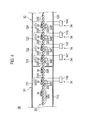
- an in-line coating device 30 of a third embodiment includes a roller conveyor 33 that includes rotating rollers to transport workpieces W as the transport section instead of the belt conveyor 13 of the first embodiment.
- the other components of the third embodiment are the substantially same as those of the first embodiment.
- the same components as those of the first embodiment are given the same reference numerals in Fig. 4 , and overlapping description is omitted.
- the roller conveyor 33 includes conductive rollers 330, 331, 332, 333, and 334 (conducting portions).
- the rollers 330 to 334 are made of metal, for example.
- the rollers 330 face the electrode 111.
- the rollers 331 face the target 121; the rollers 332 face the target 122; the rollers 333 face the target 123; and the rollers 334 face the target 124.
- the roller conveyor 33 includes insulating rollers 335.
- the rollers 335 are made of resin, for example. Some of the rollers 335 are arranged upstream of the rollers 330 in the transport direction of the workpieces W. Some of the rollers 335 are arranged between rollers 330 and rollers 331; some are arranged between the rollers 331 and rollers 332; some are arranged between the rollers 332 and rollers 333; and some are arranged between the rollers 333 and 334.
- the other rollers 335 are arranged downstream of the rollers 334 in the transport direction of the workpieces W.
- the rollers 330 to 335 are rotated by a motor.
- the voltage applying section 34 of the third embodiment includes: brushes 345 configured to come into sliding contact with the rollers 330; brushes 346 configured to come into sliding contact with the rollers 331; brushes 347 configured to come into contact with the rollers 332; brushes 348 configured to come into contact with the rollers 333; and brushes 349 configured to come into contact with the rollers 334.
- the workpiece W When the workpiece W is transported and reaches the rollers 331 and faces the target 121, the workpiece W is subjected to coating.
- the workpiece W comes into contact with the rollers 331 to be electrically connected to the rollers 331.
- the bias voltage is applied to the workpiece W through the rollers 331.
- the electrical connection between the workpiece W and power supply 141 is disconnected, and the coating of the workpiece W is thereby stopped.
- the workpiece W When the workpiece W is transported and reaches the rollers 332 and faces the target 122, the workpiece W is subjected to coating.
- the workpiece W comes into contact with the rollers 332 to be electrically connected to the rollers 332.
- the bias voltage is applied to the workpiece W through the rollers 332.
- the electrical connection between the workpiece W and power supply 142 is disconnected, and the coating of the workpiece W is thereby stopped.
- the workpiece W When the workpiece W is transported and reaches the rollers 333 and faces the target 123, the workpiece W is subjected to coating.
- the workpiece W comes into contact with the rollers 333 to be electrically connected to the rollers 333.
- the bias voltage is applied to the workpiece W through the rollers 333.
- the electrical connection between the workpiece W and power supply 143 is disconnected, and the coating of the workpiece W is thereby stopped.
- the workpiece W When the workpiece W is transported reaches the rollers 334 and faces the target 124, the workpiece W is subjected to coating.
- the workpiece W comes into contact with the rollers 334 to be electrically connected to the rollers 334.
- the bias voltage is applied to the workpiece W through the rollers 334.
- the electrical connection between the workpiece W and power supply 144 is disconnected, and the coating of the workpiece W is thereby stopped.
- the third embodiment is different from the first embodiment in that the roller conveyor 33 transports the workpieces W, but the roller conveyor 33 functions in a similar manner to the belt conveyor 13 of the first embodiment. Accordingly, the in-line coating device 30 and in-line coating method of the third embodiment exhibit the same effects as those of the first embodiment.
- an in-line coating device 40 of a fourth embodiment includes a chain conveyor 43 configured to transport the workpieces W which are hanging as the transport section instead of the belt conveyor 13 of the second embodiment.
- the other components of the fourth embodiment are the substantially same as those of the second embodiment.
- the same components as those of the second embodiment are given the same reference numerals in Fig. 5 , and overlapping description is omitted.
- the chain conveyor 43 includes: a rail 433; supporting members (conducting portions) 430 supporting the workpieces W such that the workpieces W can move relative to the rail 433; and a chain 434 connected to the supporting members 430.
- the supporting members 430 are isolated from the chain 434.
- the chain 434 links the supporting members 430 to one another.
- the chain 434 is pulled to move the supporting members 430 along the rail 433 and transport the workpieces W.
- the driving source to pull the chain 434 is a motor, for example.
- Each of the supporting members 430 includes a rail attachment 431 movably attached to the rail 433; and a hanging portion 432 which is connected to the rail attachment 431 and on which a workpiece W is hung.
- the rail attachment 431 is configured to be hooked on the rail 433 and includes wheels rolling along the rail 433, for example.
- the hanging portion 432 has a frame shape that fits on the edge of the workpiece W.
- the supporting member 430 is conductive.
- the supporting member 430 is electrically connected to the workpiece W.
- the voltage applying section 44 of the fourth embodiment includes brushes 445, 446, 447, 448, and 449 which come into sliding contact with each supporting member 430.
- the power supply 140 is electrically connected to the brush 445.
- the power supply 140 is electrically connected to the electrodes 211.
- the power supply 141 is electrically connected to the brush 446.
- the power supply 141 is electrically connected to the targets 221.
- the power supply 142 is electrically connected to the brush 447.
- the power supply 142 is electrically connected to the targets 222.
- the power supply 143 is electrically connected to the brush 448.
- the power supply 143 is electrically connected to the targets 223.
- the power supply 144 is electrically connected to the brush 449.
- the power supply 144 is electrically connected to the targets 224.
- each supporting member 430 moves along the rail 433 to come into contact with the brush 445 and the workpiece W faces the electrodes 211, the workpiece W is subjected to bombardment. Since the electrodes 211 are placed so as to face the both surfaces of the workpiece W, the both surfaces of the workpiece W are bombarded.
- the supporting member 430 is electrically connected to the brush 445. The bias voltage is applied to the workpiece W through the supporting member 430.
- the supporting member 430 moves apart from the brush 445, the electrical connection between the workpiece W and power supply 140 is disconnected between the supporting members 430, and the bombardment is thereby stopped.
- the supporting member 430 moves along the rail 433 to come into contact with the brush 446 and the workpiece W faces the electrodes 211, the workpiece W is subjected to coating. Since the targets 211 are placed so as to face the both surfaces of the workpiece W, the both surfaces of the workpiece W are coated.
- the supporting member 430 is electrically connected to the brush 446.
- the electrical connection between the workpiece W and power supply 140 is disconnected between the supporting members 430, and the coating is thereby stopped.
- the fourth embodiment is different from the second embodiment in that the chain conveyor 43 transports the workpieces W that are hanging.
- the chain conveyor 43 functions in a similar manner to the belt conveyor 13 and jigs 23 of the second embodiment. Accordingly, the in-line coating device 40 and in-line coating method of the fourth embodiment exhibit the same effects as those of the second embodiment.
- an in-line coating device 50 of a fifth embodiment transports hanging workpieces W2 while coating the same in a similar manner to the fourth embodiment but is different from that of the fourth embodiment in terms of the shape of the workpieces W2 and the configuration of the transport section to transport the workpieces W2.
- the same components as those of the fourth embodiment are given the same reference numerals in Fig. 6 .
- the transport section includes a linear member 53 extending in the transport direction of the workpieces W2.
- the linear member 53 is pulled by a driving device including a motor and the like, for example, to move in the longitudinal direction.
- the workpieces W2 move together with the liner member 53.
- the linear member 53 includes cables 530 on which the workpieces W2 are hung; and insulators 531 provided between the cables 530.
- the workpieces W2 adjacent to each other are isolated by each insulator 531.
- each workpiece W2 has a bent portion W21 (a hook portion), which is formed by bending an end of the workpiece W2.
- the workpiece W2 is hung with the bent portion W21 hooked on the cable 530.
- the bent portions W21 cover the cables 530 so that the cables 530 are not exposed to the targets 221 to 224.
- the voltage applying section 54 of the fifth embodiment includes brushes 545, 546, 547, 548, and 549 each of which alternately comes into sliding contact with the insulators 531 and bent portions W21.
- the electrodes 211, targets 221 to 224, power supplies 140 to 144 are the same as those of the fourth embodiment.
- the brushes 545 is electrically connected to the power supply 140, respectively.
- the brushes 546 is electrically connected to the power supply 141, respectively.
- the brushes 547 is electrically connected to the power supply 142, respectively.
- the brushes 548 is electrically connected to the power supply 143, respectively.
- the brushes 549 is electrically connected to the power supply 144, respectively.
- the targets 222 face the workpiece W2, and the brush 547 is electrically connected to the workpiece W2 to apply the bias voltage to the workpiece W2.
- the targets 224 face the workpiece W2, and the brush 549 is electrically connected to the workpiece W2 to apply the bias voltage to the workpiece W2.
- each workpiece W2 faces the electrodes 211 and faces the targets 221 to 224
- different bias voltages are applied to the workpiece W2.
- the both surfaces of the workpiece W2 are simultaneously bombarded when the workpiece W2 faces the electrodes 211.
- the both surfaces of the workpiece W2 are simultaneously coated when the workpiece W2 faces each pair of the targets 221 to 224.
- the bent portion W21 is unnecessary after coating and is removed, thus forming a separator S used in polymer electrolyte fuel cells.
- the bent portion W21 is removed by cutting using a blade B or a laser beam, for example.
- the separator S includes: a base material S1 as the workpiece W2; and coating layers S2 and S3 formed on the surface of the base material S1.
- Examples of the material constituting the coating layers S1 are iron, titanium, aluminum, and alloys thereof, for example.
- the iron alloys include stainless.
- the coating layer S2 is formed when the workpiece W2 passes between the targets 221 and then passes between the targets 222.
- the coating layer S2 includes a double-layer structure in which the layer formed when the workpiece W2 passes between the targets 222 is laid on the layer formed when the workpiece W2 passes between the targets 221.
- the properties of the two layers can be individually changed by changing the bias voltages.
- Examples of the material constituting the coating layer S2 are chrome (Cr), tungsten (W), titanium (Ti), molybdenum (Mo), niobium (Nb), and hafnium (Hf), nitrides thereof, carbides thereof, and carbonitrides thereof.
- the material constituting the coating layer S2 is not limited to these materials.
- the material constituting the coating layer S2 can be changed by changing the materials constituting the targets 221 and 222.
- the coating layer S3 is formed when the workpiece W2 passes between the targets 223 and passes between the targets 224.
- the coating layer S3 includes a double-layer structure in which the layer formed when the workpiece W2 passes between the targets 223 is laid on the layer formed when the workpiece W2 passes between the targets 224.
- the properties of the two layers, such as conductivity or hardness, for example, can be individually changed by changing the bias voltages.
- the coating layer S3 is made of diamond-like carbon (DLC), for example, but is not limited to DLC.
- DLC diamond-like carbon
- the material constituting the coating layer S3 can be changed by changing the materials constituting the targets 223 and 224.
- the base material S1 and separator S have a rectangular shape in a plan view illustrated in Fig. 9 .
- An end face S4 constituting one side in the periphery of the rectangular shape has a different characteristic from that of the end faces S5, S6, and S7.
- the end face S4 is a cut surface formed by cutting the bent portion W21 as an end of the base material S1 unlike the end faces S5 to S7.
- the coating materials adhere to the end faces S5 to S7 of the base material S1 during the process of coating.
- the proportion of an area in the end face S4 as cut surface, to which the coating materials do not adhere, that is, to which the substrate S1 is exposed is higher than those of the end faces S5 to S7.
- the configuration in which the end face S4 has a different characteristic from that of the end faces S5 to S7 constituting the other sides is not limited to the above-described configuration in which the end face S4 is different from the end faces S5 to S7 in terms of the proportion of the area to which the base material S1 is exposed.
- the configuration includes the configuration in which the end face S4 is not linear and has a different shape from that of the other end faces S5 to S7 in the plan view illustrated in Fig. 9 , for example.
- the workpieces W2 cover the cables 530 that face the targets 221 to 224 when the bias voltages are applied to the workpieces W2.
- This can prevent the coating materials from adhering to the transport section and therefore reduce the efforts of maintenance to remove the unnecessary coating materials adhering to the transport section by blasting or the like. Accordingly, the fifth embodiment exhibits the effect on further improving the mass production in addition to the effects of the fourth embodiment.
- the insulators 531 do not face the targets 221 to 224 when the bias voltage is applied to the workpiece W2, and the coating materials are not deposited on the insulators 531.
- the coating materials are prevented from adhering to the transport section, the coating materials are also prevented from peeling off and adhering to the workpieces W2 as foreign matters. This can improve the percentage of non-defective products.
- bent portions W21 are hooked on the cables 530, it is possible to apply appropriate bias voltages corresponding to the targets 221 to 224 to the transported workpieces W2 through the bent portions W21.
- the transport section does not need to include jigs to hang the workpieces W2, thus simplifying the configuration of the transport section. Moreover, there is no need for the trouble of setting the workpieces W2 to jigs to hang the workpieces W2, thus facilitating the operation.
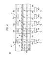
- an in-line coating device 60 of a sixth embodiment is different from that of the first embodiment in terms of the configuration of a belt conveyor 63 as the transport section and the position of each workpiece W on the belt conveyor 63.
- the other components of the sixth embodiment are the substantially same as those of the first embodiment.
- the same components in Fig. 10 as those of the first embodiment are given the same reference numerals.
- the belt conveyor 63 includes conducting portions 630 and insulators 631 which are alternately arranged in the transport direction.
- the conducting portions 630 and insulators 631 constitute a belt.
- the conducting portions 630 are made of metal, for example.
- the insulators 631 are made of resin, for example.
- the conducting portions 630 have a flat plate shape.
- the insulators 631 protrude in the thickness direction of the conducting portions 630.
- the conducting portions 630 adjacent to each other are isolated by each insulator 631.
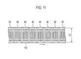
- Each workpiece W is arranged at an angle between adjacent ones of the insulators 631, which are spaced from one another in the transport direction, such that an end of the workpiece W abuts on a side of one of the adjacent insulators 631 and the other end is arranged on the other insulator 631.
- the workpieces W adjacent to each other are isolated by each insulator 631.
- the workpieces W are in contact with the conducting portions 630 and are electrically connected to the conducting portions 630.
- each conducting portion 630 moves and comes into contact with the brush 145, the bias voltage is applied to the workpiece W from the power supply 140 through the conducting portion 630, and the workpiece W is subjected to bombardment.
- the conducting portion 630 moves and comes into contact with the brush 146, the bias voltage is applied to the workpiece W from the power supply 141 through the conducting portion 630, and the workpiece W is subjected to coating.
- the conducting portion 630 moves and comes into contact with the brush 147, the bias voltage is applied to the workpiece W from the power supply 142 through the conducting portion 630, and the workpiece W is subjected to coating.
- the conducting portion 630 moves and comes into contact with the brush 148, the bias voltage is applied to the workpiece W from the power supply 143 through the conducting portion 630, and the workpiece W is subjected to coating.
- the conducting portion 630 moves and comes into contact with the brush 149, the bias voltage is applied to the workpiece W from the power supply 144 through the conducting portion 630, and the workpiece W is subjected to coating.
- the workpieces W cover the conducting portions 630 and insulators 631.
- the size in the transport direction, of the projection of each workpiece W projected in the direction orthogonal to the surface of the belt is substantially equal to a width L1 of the adjacent conducting portion 630 and insulator 631 in the transport direction.
- the size of the workpiece W in the direction which is orthogonal to the transport direction and parallel to the surface of the belt is equal to or more than a width L2 of the belt.
- the workpieces W cover the entire upper surface of the belt that faces the targets 121 to 124.
- the coating materials are therefore prevented from adhering to the belt conveyor 63 in the process of coating.
- the device similarly to the fifth embodiment, the device can be easily maintained, and the percentage of non-defective products is improved.
- the workpieces are coated by sputtering but are not limited to this case.
- the workpieces may be coated by another process of coating by applying bias voltage to the workpieces, such as ion plating, for example.
- bias voltage such as ion plating
- vapor sources which are heated using electron beams and the like to evaporate the coating materials and emit gas particles are used instead of the targets 121 to 124 and 221 and 224 of the above-described embodiments.
- the oxide film removing section it is only necessary to remove the oxide film on the surface of each workpiece by bombardment.
- the oxide film removing section may include an ion gun emitting accelerated ions toward the workpieces instead of the electrodes 111 and 211 of the aforementioned embodiments.
Landscapes
- Chemical & Material Sciences (AREA)
- Chemical Kinetics & Catalysis (AREA)
- Engineering & Computer Science (AREA)
- Materials Engineering (AREA)
- Mechanical Engineering (AREA)
- Metallurgy (AREA)
- Organic Chemistry (AREA)
- Life Sciences & Earth Sciences (AREA)
- Composite Materials (AREA)
- Manufacturing & Machinery (AREA)
- Sustainable Development (AREA)
- Sustainable Energy (AREA)
- Electrochemistry (AREA)
- General Chemical & Material Sciences (AREA)
- Physical Vapour Deposition (AREA)
- Fuel Cell (AREA)
- Coating Apparatus (AREA)
Applications Claiming Priority (3)
| Application Number | Priority Date | Filing Date | Title |
|---|---|---|---|
| JP2012219459 | 2012-10-01 | ||
| JP2013140834 | 2013-07-04 | ||
| PCT/JP2013/076570 WO2014054587A1 (ja) | 2012-10-01 | 2013-09-30 | インライン式コーティング装置、インライン式コーティング方法、およびセパレータ |
Publications (3)
| Publication Number | Publication Date |
|---|---|
| EP2905355A1 true EP2905355A1 (de) | 2015-08-12 |
| EP2905355A4 EP2905355A4 (de) | 2015-11-11 |
| EP2905355B1 EP2905355B1 (de) | 2018-05-09 |
Family
ID=50434914
Family Applications (1)
| Application Number | Title | Priority Date | Filing Date |
|---|---|---|---|
| EP13843240.6A Not-in-force EP2905355B1 (de) | 2012-10-01 | 2013-09-30 | Inline-beschichtungsvorrichtung und inline-beschichtungsverfahren |
Country Status (6)
| Country | Link |
|---|---|
| US (1) | US10941483B2 (de) |
| EP (1) | EP2905355B1 (de) |
| JP (1) | JP5999190B2 (de) |
| CN (1) | CN104704140B (de) |
| CA (1) | CA2886976C (de) |
| WO (1) | WO2014054587A1 (de) |
Cited By (1)
| Publication number | Priority date | Publication date | Assignee | Title |
|---|---|---|---|---|
| DE102018115404A1 (de) | 2018-06-27 | 2020-01-02 | Schaeffler Technologies AG & Co. KG | Verfahren und Vorrichtung zur Beschichtung eines Bauteils mittels physikalischer Gasphasenabscheidung |
Families Citing this family (8)
| Publication number | Priority date | Publication date | Assignee | Title |
|---|---|---|---|---|
| DE102015116738A1 (de) * | 2015-10-02 | 2017-04-06 | Von Ardenne Gmbh | Substratträger, Transportsystemanordnung und Substratbehandlungsanlage |
| JP6614482B2 (ja) * | 2015-10-06 | 2019-12-04 | 日産自動車株式会社 | 燃料電池の製造方法および燃料電池の製造装置 |
| JP6512579B2 (ja) * | 2015-10-06 | 2019-05-15 | 日産自動車株式会社 | 燃料電池の製造方法および燃料電池の製造装置 |
| JP6379318B1 (ja) * | 2017-06-14 | 2018-08-22 | 株式会社アルバック | 成膜装置及び成膜方法並びに太陽電池の製造方法 |
| EP3778982B1 (de) | 2019-08-14 | 2023-07-05 | IHI Hauzer Techno Coating B.V. | Verfahren zum beschichten einer oder mehrerer metallkomponenten eines brennstoffzellenstapels, komponente eines brennstoffzellenstapels und vorrichtung zum beschichten einer oder mehrerer komponenten eines brennstoffzellenstapels |
| JP7587937B2 (ja) * | 2020-08-07 | 2024-11-21 | 株式会社アルバック | 導電膜の形成方法、および、成膜装置 |
| CN117836463A (zh) * | 2021-09-28 | 2024-04-05 | 芝浦机械株式会社 | 表面处理装置 |
| DE102024106587A1 (de) * | 2024-03-07 | 2025-09-11 | VON ARDENNE Asset GmbH & Co. KG | Transportsystem, Vakuumanordnung und Substratträger |
Family Cites Families (22)
| Publication number | Priority date | Publication date | Assignee | Title |
|---|---|---|---|---|
| DE2844491C2 (de) * | 1978-10-12 | 1983-04-14 | Leybold-Heraeus GmbH, 5000 Köln | Vakuum-Beschichtungsanlage mit einer Einrichtung zum kontinuierlichen Substrattransport |
| JPS6389660A (ja) | 1986-10-01 | 1988-04-20 | Konica Corp | 蛍光体蒸着装置 |
| JPH07334843A (ja) | 1994-06-03 | 1995-12-22 | Fuji Electric Co Ltd | 磁気記録媒体の製造方法 |
| JP3732250B2 (ja) * | 1995-03-30 | 2006-01-05 | キヤノンアネルバ株式会社 | インライン式成膜装置 |
| JP3002632B2 (ja) * | 1995-06-22 | 2000-01-24 | ホーヤ株式会社 | 磁気記録媒体の製造方法及び基板ホルダ |
| US6726993B2 (en) * | 1997-12-02 | 2004-04-27 | Teer Coatings Limited | Carbon coatings, method and apparatus for applying them, and articles bearing such coatings |
| JP4227720B2 (ja) | 2000-06-21 | 2009-02-18 | キヤノンアネルバ株式会社 | 情報記録ディスク製造装置及び製造方法並びにプラズマアッシング方法 |
| US6886244B1 (en) | 2002-02-25 | 2005-05-03 | Seagate Technology Llc | Segmented pallet for disk-shaped substrate electrical biassing and apparatus comprising same |
| US7041202B2 (en) * | 2002-08-02 | 2006-05-09 | Seagate Technology Llc | Timing apparatus and method to selectively bias during sputtering |
| JP4671579B2 (ja) * | 2002-12-16 | 2011-04-20 | 株式会社アルバック | Ag合金反射膜およびその製造方法 |
| JP2005190968A (ja) * | 2003-12-26 | 2005-07-14 | Daido Steel Co Ltd | 燃料電池用金属セパレータ、燃料電池用金属セパレータの製造方法及び燃料電池 |
| US8088536B2 (en) * | 2004-09-10 | 2012-01-03 | Neomax Materials Co., Ltd. | Fuel cell separator and method for manufacturing the same |
| JP4657959B2 (ja) * | 2006-03-20 | 2011-03-23 | ダブリュディ・メディア・シンガポール・プライベートリミテッド | 成膜装置及び磁気ディスクの製造方法 |
| EP2044237B1 (de) * | 2006-07-13 | 2020-12-16 | Teer Coatings Limited | Verfahren zur beschichtung |
| US20080085439A1 (en) * | 2006-09-28 | 2008-04-10 | Hilliard Donald B | Solid oxide electrolytic device |
| JP5262150B2 (ja) | 2008-02-05 | 2013-08-14 | 日産自動車株式会社 | 燃料電池用金属セパレータの製造方法および製造装置 |
| DE102009004493B3 (de) | 2009-01-09 | 2010-06-10 | Sovello Ag | Vakuumbeschichtungsanlage und Verfahren zum Betrieb einer Vakuumbeschichtungsanlage |
| JP2010272490A (ja) | 2009-05-25 | 2010-12-02 | Nissan Motor Co Ltd | 燃料電池構成部品用表面処理部材ならびにその製造方法 |
| KR101242986B1 (ko) * | 2010-03-22 | 2013-03-12 | 현대하이스코 주식회사 | 연료전지용 금속 분리판 제조 방법 |
| JP5712518B2 (ja) | 2010-07-16 | 2015-05-07 | 日産自動車株式会社 | 導電部材の製造方法 |
| JP5656019B2 (ja) * | 2011-03-08 | 2015-01-21 | 日産自動車株式会社 | 被膜形成装置 |
| GB201203219D0 (en) * | 2012-02-24 | 2012-04-11 | Teer Coatings Ltd | Coating with conductive and corrosion resistance characteristics |
-
2013
- 2013-09-30 WO PCT/JP2013/076570 patent/WO2014054587A1/ja not_active Ceased
- 2013-09-30 CN CN201380051472.3A patent/CN104704140B/zh not_active Expired - Fee Related
- 2013-09-30 CA CA2886976A patent/CA2886976C/en not_active Expired - Fee Related
- 2013-09-30 US US14/432,645 patent/US10941483B2/en not_active Expired - Fee Related
- 2013-09-30 EP EP13843240.6A patent/EP2905355B1/de not_active Not-in-force
- 2013-09-30 JP JP2014539732A patent/JP5999190B2/ja not_active Expired - Fee Related
Cited By (2)
| Publication number | Priority date | Publication date | Assignee | Title |
|---|---|---|---|---|
| DE102018115404A1 (de) | 2018-06-27 | 2020-01-02 | Schaeffler Technologies AG & Co. KG | Verfahren und Vorrichtung zur Beschichtung eines Bauteils mittels physikalischer Gasphasenabscheidung |
| WO2020001676A1 (de) | 2018-06-27 | 2020-01-02 | Schaeffler Technologies AG & Co. KG | Verfahren und vorrichtung zur beschichtung eines bauteils mittels physikalischer gasphasenabscheidung |
Also Published As
| Publication number | Publication date |
|---|---|
| EP2905355B1 (de) | 2018-05-09 |
| CN104704140B (zh) | 2019-03-12 |
| US20150240346A1 (en) | 2015-08-27 |
| JP5999190B2 (ja) | 2016-09-28 |
| CN104704140A (zh) | 2015-06-10 |
| EP2905355A4 (de) | 2015-11-11 |
| US10941483B2 (en) | 2021-03-09 |
| JPWO2014054587A1 (ja) | 2016-08-25 |
| WO2014054587A1 (ja) | 2014-04-10 |
| CA2886976A1 (en) | 2014-04-10 |
| CA2886976C (en) | 2020-01-21 |
Similar Documents
| Publication | Publication Date | Title |
|---|---|---|
| EP2905355B1 (de) | Inline-beschichtungsvorrichtung und inline-beschichtungsverfahren | |
| CN114930490B (zh) | 溅射沉积设备和方法 | |
| CN114846575B (zh) | 溅射沉积设备和方法 | |
| US20200318233A1 (en) | Deposition apparatus, method of coating a flexible substrate and flexible substrate having a coating | |
| WO2021094731A1 (en) | Sputter deposition apparatus and method | |
| CN104294224B (zh) | 溅射装置和带薄膜的长条膜的制造方法 | |
| WO2011111712A1 (ja) | スパッタ装置 | |
| KR101386200B1 (ko) | 스퍼터 코팅 장치 및 진공 코팅 장치 | |
| WO2018113904A1 (en) | Sputter deposition source and method of depositing a layer on a substrate | |
| WO2017050350A1 (en) | Substrate carrier, and sputter deposition apparatus and method using the same | |
| WO2019105533A1 (en) | Deposition apparatus for coating a flexible substrate, method of coating a flexible substrate and flexible substrate having a coating | |
| JP5929835B2 (ja) | 長尺樹脂フィルムの表面処理装置及び表面処理方法、並びに該表面処理装置を備えたロールツーロール成膜装置 | |
| US10982321B2 (en) | Homogeneous HiPIMS coating method | |
| CN111699277B (zh) | 沉积设备、涂覆柔性基板的方法和具有涂层的柔性基板 | |
| WO2023089200A2 (en) | In-line coating apparatus for the manufacture of parts of a solid-state cell | |
| US10184171B2 (en) | Sputtering apparatus and method thereof | |
| EP3647457B1 (de) | Filmbehandlungsverfahren und filmherstellungsverfahren | |
| US20120045591A1 (en) | Plasma processing apparatus, deposition method, method of manufacturing metal plate having dlc film, method of manufacturing separator, and method of manufacturing article | |
| JP5095087B2 (ja) | 成膜装置及び成膜方法 | |
| KR20090088302A (ko) | 기판 처리를 위한 장치 | |
| JP4211757B2 (ja) | 金属膜形成方法 | |
| KR101732712B1 (ko) | 플라즈마 화학 기상 증착 장치 및 증착 방법 | |
| WO2013024641A1 (ja) | スパッタリング装置およびその成膜方法 | |
| KR20160130666A (ko) | 마그네트론 스퍼터링 증착 장치 및 증착 방법 |
Legal Events
| Date | Code | Title | Description |
|---|---|---|---|
| PUAI | Public reference made under article 153(3) epc to a published international application that has entered the european phase |
Free format text: ORIGINAL CODE: 0009012 |
|
| 17P | Request for examination filed |
Effective date: 20150416 |
|
| AK | Designated contracting states |
Kind code of ref document: A1 Designated state(s): AL AT BE BG CH CY CZ DE DK EE ES FI FR GB GR HR HU IE IS IT LI LT LU LV MC MK MT NL NO PL PT RO RS SE SI SK SM TR |
|
| AX | Request for extension of the european patent |
Extension state: BA ME |
|
| RA4 | Supplementary search report drawn up and despatched (corrected) |
Effective date: 20151012 |
|
| RIC1 | Information provided on ipc code assigned before grant |
Ipc: H01M 8/02 20060101ALI20151006BHEP Ipc: C23C 14/56 20060101AFI20151006BHEP |
|
| DAX | Request for extension of the european patent (deleted) | ||
| 17Q | First examination report despatched |
Effective date: 20170428 |
|
| GRAP | Despatch of communication of intention to grant a patent |
Free format text: ORIGINAL CODE: EPIDOSNIGR1 |
|
| INTG | Intention to grant announced |
Effective date: 20180109 |
|
| RAX | Requested extension states of the european patent have changed |
Extension state: BA Extension state: ME |
|
| GRAS | Grant fee paid |
Free format text: ORIGINAL CODE: EPIDOSNIGR3 |
|
| GRAA | (expected) grant |
Free format text: ORIGINAL CODE: 0009210 |
|
| AK | Designated contracting states |
Kind code of ref document: B1 Designated state(s): AL AT BE BG CH CY CZ DE DK EE ES FI FR GB GR HR HU IE IS IT LI LT LU LV MC MK MT NL NO PL PT RO RS SE SI SK SM TR |
|
| DAX | Request for extension of the european patent (deleted) | ||
| RAP1 | Party data changed (applicant data changed or rights of an application transferred) |
Owner name: NISSAN MOTOR CO., LTD. |
|
| REG | Reference to a national code |
Ref country code: GB Ref legal event code: FG4D |
|
| REG | Reference to a national code |
Ref country code: CH Ref legal event code: EP Ref country code: AT Ref legal event code: REF Ref document number: 997635 Country of ref document: AT Kind code of ref document: T Effective date: 20180515 |
|
| REG | Reference to a national code |
Ref country code: IE Ref legal event code: FG4D |
|
| REG | Reference to a national code |
Ref country code: DE Ref legal event code: R096 Ref document number: 602013037338 Country of ref document: DE |
|
| REG | Reference to a national code |
Ref country code: NL Ref legal event code: MP Effective date: 20180509 |
|
| REG | Reference to a national code |
Ref country code: FR Ref legal event code: PLFP Year of fee payment: 6 |
|
| REG | Reference to a national code |
Ref country code: LT Ref legal event code: MG4D |
|
| PG25 | Lapsed in a contracting state [announced via postgrant information from national office to epo] |
Ref country code: FI Free format text: LAPSE BECAUSE OF FAILURE TO SUBMIT A TRANSLATION OF THE DESCRIPTION OR TO PAY THE FEE WITHIN THE PRESCRIBED TIME-LIMIT Effective date: 20180509 Ref country code: LT Free format text: LAPSE BECAUSE OF FAILURE TO SUBMIT A TRANSLATION OF THE DESCRIPTION OR TO PAY THE FEE WITHIN THE PRESCRIBED TIME-LIMIT Effective date: 20180509 Ref country code: BG Free format text: LAPSE BECAUSE OF FAILURE TO SUBMIT A TRANSLATION OF THE DESCRIPTION OR TO PAY THE FEE WITHIN THE PRESCRIBED TIME-LIMIT Effective date: 20180809 Ref country code: SE Free format text: LAPSE BECAUSE OF FAILURE TO SUBMIT A TRANSLATION OF THE DESCRIPTION OR TO PAY THE FEE WITHIN THE PRESCRIBED TIME-LIMIT Effective date: 20180509 Ref country code: NO Free format text: LAPSE BECAUSE OF FAILURE TO SUBMIT A TRANSLATION OF THE DESCRIPTION OR TO PAY THE FEE WITHIN THE PRESCRIBED TIME-LIMIT Effective date: 20180809 Ref country code: ES Free format text: LAPSE BECAUSE OF FAILURE TO SUBMIT A TRANSLATION OF THE DESCRIPTION OR TO PAY THE FEE WITHIN THE PRESCRIBED TIME-LIMIT Effective date: 20180509 |
|
| PG25 | Lapsed in a contracting state [announced via postgrant information from national office to epo] |
Ref country code: GR Free format text: LAPSE BECAUSE OF FAILURE TO SUBMIT A TRANSLATION OF THE DESCRIPTION OR TO PAY THE FEE WITHIN THE PRESCRIBED TIME-LIMIT Effective date: 20180810 Ref country code: NL Free format text: LAPSE BECAUSE OF FAILURE TO SUBMIT A TRANSLATION OF THE DESCRIPTION OR TO PAY THE FEE WITHIN THE PRESCRIBED TIME-LIMIT Effective date: 20180509 Ref country code: RS Free format text: LAPSE BECAUSE OF FAILURE TO SUBMIT A TRANSLATION OF THE DESCRIPTION OR TO PAY THE FEE WITHIN THE PRESCRIBED TIME-LIMIT Effective date: 20180509 Ref country code: HR Free format text: LAPSE BECAUSE OF FAILURE TO SUBMIT A TRANSLATION OF THE DESCRIPTION OR TO PAY THE FEE WITHIN THE PRESCRIBED TIME-LIMIT Effective date: 20180509 Ref country code: LV Free format text: LAPSE BECAUSE OF FAILURE TO SUBMIT A TRANSLATION OF THE DESCRIPTION OR TO PAY THE FEE WITHIN THE PRESCRIBED TIME-LIMIT Effective date: 20180509 |
|
| REG | Reference to a national code |
Ref country code: AT Ref legal event code: MK05 Ref document number: 997635 Country of ref document: AT Kind code of ref document: T Effective date: 20180509 |
|
| PG25 | Lapsed in a contracting state [announced via postgrant information from national office to epo] |
Ref country code: AT Free format text: LAPSE BECAUSE OF FAILURE TO SUBMIT A TRANSLATION OF THE DESCRIPTION OR TO PAY THE FEE WITHIN THE PRESCRIBED TIME-LIMIT Effective date: 20180509 Ref country code: EE Free format text: LAPSE BECAUSE OF FAILURE TO SUBMIT A TRANSLATION OF THE DESCRIPTION OR TO PAY THE FEE WITHIN THE PRESCRIBED TIME-LIMIT Effective date: 20180509 Ref country code: DK Free format text: LAPSE BECAUSE OF FAILURE TO SUBMIT A TRANSLATION OF THE DESCRIPTION OR TO PAY THE FEE WITHIN THE PRESCRIBED TIME-LIMIT Effective date: 20180509 Ref country code: CZ Free format text: LAPSE BECAUSE OF FAILURE TO SUBMIT A TRANSLATION OF THE DESCRIPTION OR TO PAY THE FEE WITHIN THE PRESCRIBED TIME-LIMIT Effective date: 20180509 Ref country code: SK Free format text: LAPSE BECAUSE OF FAILURE TO SUBMIT A TRANSLATION OF THE DESCRIPTION OR TO PAY THE FEE WITHIN THE PRESCRIBED TIME-LIMIT Effective date: 20180509 Ref country code: RO Free format text: LAPSE BECAUSE OF FAILURE TO SUBMIT A TRANSLATION OF THE DESCRIPTION OR TO PAY THE FEE WITHIN THE PRESCRIBED TIME-LIMIT Effective date: 20180509 Ref country code: PL Free format text: LAPSE BECAUSE OF FAILURE TO SUBMIT A TRANSLATION OF THE DESCRIPTION OR TO PAY THE FEE WITHIN THE PRESCRIBED TIME-LIMIT Effective date: 20180509 |
|
| REG | Reference to a national code |
Ref country code: DE Ref legal event code: R097 Ref document number: 602013037338 Country of ref document: DE |
|
| PG25 | Lapsed in a contracting state [announced via postgrant information from national office to epo] |
Ref country code: SM Free format text: LAPSE BECAUSE OF FAILURE TO SUBMIT A TRANSLATION OF THE DESCRIPTION OR TO PAY THE FEE WITHIN THE PRESCRIBED TIME-LIMIT Effective date: 20180509 Ref country code: IT Free format text: LAPSE BECAUSE OF FAILURE TO SUBMIT A TRANSLATION OF THE DESCRIPTION OR TO PAY THE FEE WITHIN THE PRESCRIBED TIME-LIMIT Effective date: 20180509 |
|
| PLBE | No opposition filed within time limit |
Free format text: ORIGINAL CODE: 0009261 |
|
| STAA | Information on the status of an ep patent application or granted ep patent |
Free format text: STATUS: NO OPPOSITION FILED WITHIN TIME LIMIT |
|
| 26N | No opposition filed |
Effective date: 20190212 |
|
| PG25 | Lapsed in a contracting state [announced via postgrant information from national office to epo] |
Ref country code: MC Free format text: LAPSE BECAUSE OF FAILURE TO SUBMIT A TRANSLATION OF THE DESCRIPTION OR TO PAY THE FEE WITHIN THE PRESCRIBED TIME-LIMIT Effective date: 20180509 |
|
| REG | Reference to a national code |
Ref country code: CH Ref legal event code: PL |
|
| PG25 | Lapsed in a contracting state [announced via postgrant information from national office to epo] |
Ref country code: SI Free format text: LAPSE BECAUSE OF FAILURE TO SUBMIT A TRANSLATION OF THE DESCRIPTION OR TO PAY THE FEE WITHIN THE PRESCRIBED TIME-LIMIT Effective date: 20180509 |
|
| REG | Reference to a national code |
Ref country code: BE Ref legal event code: MM Effective date: 20180930 |
|
| REG | Reference to a national code |
Ref country code: IE Ref legal event code: MM4A |
|
| PG25 | Lapsed in a contracting state [announced via postgrant information from national office to epo] |
Ref country code: LU Free format text: LAPSE BECAUSE OF NON-PAYMENT OF DUE FEES Effective date: 20180930 |
|
| PG25 | Lapsed in a contracting state [announced via postgrant information from national office to epo] |
Ref country code: IE Free format text: LAPSE BECAUSE OF NON-PAYMENT OF DUE FEES Effective date: 20180930 |
|
| PG25 | Lapsed in a contracting state [announced via postgrant information from national office to epo] |
Ref country code: CH Free format text: LAPSE BECAUSE OF NON-PAYMENT OF DUE FEES Effective date: 20180930 Ref country code: LI Free format text: LAPSE BECAUSE OF NON-PAYMENT OF DUE FEES Effective date: 20180930 Ref country code: BE Free format text: LAPSE BECAUSE OF NON-PAYMENT OF DUE FEES Effective date: 20180930 |
|
| PG25 | Lapsed in a contracting state [announced via postgrant information from national office to epo] |
Ref country code: AL Free format text: LAPSE BECAUSE OF FAILURE TO SUBMIT A TRANSLATION OF THE DESCRIPTION OR TO PAY THE FEE WITHIN THE PRESCRIBED TIME-LIMIT Effective date: 20180509 |
|
| PG25 | Lapsed in a contracting state [announced via postgrant information from national office to epo] |
Ref country code: MT Free format text: LAPSE BECAUSE OF NON-PAYMENT OF DUE FEES Effective date: 20180930 |
|
| PG25 | Lapsed in a contracting state [announced via postgrant information from national office to epo] |
Ref country code: TR Free format text: LAPSE BECAUSE OF FAILURE TO SUBMIT A TRANSLATION OF THE DESCRIPTION OR TO PAY THE FEE WITHIN THE PRESCRIBED TIME-LIMIT Effective date: 20180509 |
|
| PG25 | Lapsed in a contracting state [announced via postgrant information from national office to epo] |
Ref country code: PT Free format text: LAPSE BECAUSE OF FAILURE TO SUBMIT A TRANSLATION OF THE DESCRIPTION OR TO PAY THE FEE WITHIN THE PRESCRIBED TIME-LIMIT Effective date: 20180509 |
|
| PG25 | Lapsed in a contracting state [announced via postgrant information from national office to epo] |
Ref country code: CY Free format text: LAPSE BECAUSE OF FAILURE TO SUBMIT A TRANSLATION OF THE DESCRIPTION OR TO PAY THE FEE WITHIN THE PRESCRIBED TIME-LIMIT Effective date: 20180509 Ref country code: MK Free format text: LAPSE BECAUSE OF NON-PAYMENT OF DUE FEES Effective date: 20180509 Ref country code: HU Free format text: LAPSE BECAUSE OF FAILURE TO SUBMIT A TRANSLATION OF THE DESCRIPTION OR TO PAY THE FEE WITHIN THE PRESCRIBED TIME-LIMIT; INVALID AB INITIO Effective date: 20130930 |
|
| PG25 | Lapsed in a contracting state [announced via postgrant information from national office to epo] |
Ref country code: IS Free format text: LAPSE BECAUSE OF FAILURE TO SUBMIT A TRANSLATION OF THE DESCRIPTION OR TO PAY THE FEE WITHIN THE PRESCRIBED TIME-LIMIT Effective date: 20180909 |
|
| PGFP | Annual fee paid to national office [announced via postgrant information from national office to epo] |
Ref country code: FR Payment date: 20210812 Year of fee payment: 9 |
|
| PGFP | Annual fee paid to national office [announced via postgrant information from national office to epo] |
Ref country code: DE Payment date: 20210818 Year of fee payment: 9 Ref country code: GB Payment date: 20210825 Year of fee payment: 9 |
|
| REG | Reference to a national code |
Ref country code: DE Ref legal event code: R119 Ref document number: 602013037338 Country of ref document: DE |
|
| GBPC | Gb: european patent ceased through non-payment of renewal fee |
Effective date: 20220930 |
|
| PG25 | Lapsed in a contracting state [announced via postgrant information from national office to epo] |
Ref country code: FR Free format text: LAPSE BECAUSE OF NON-PAYMENT OF DUE FEES Effective date: 20220930 Ref country code: DE Free format text: LAPSE BECAUSE OF NON-PAYMENT OF DUE FEES Effective date: 20230401 |
|
| PG25 | Lapsed in a contracting state [announced via postgrant information from national office to epo] |
Ref country code: GB Free format text: LAPSE BECAUSE OF NON-PAYMENT OF DUE FEES Effective date: 20220930 |