EP2907406A1 - Dispositif de réglage pour serrer ou desserrer un lacet - Google Patents
Dispositif de réglage pour serrer ou desserrer un lacet Download PDFInfo
- Publication number
- EP2907406A1 EP2907406A1 EP15150050.1A EP15150050A EP2907406A1 EP 2907406 A1 EP2907406 A1 EP 2907406A1 EP 15150050 A EP15150050 A EP 15150050A EP 2907406 A1 EP2907406 A1 EP 2907406A1
- Authority
- EP
- European Patent Office
- Prior art keywords
- adjusting device
- knob
- releasing unit
- limiting portion
- stopping
- Prior art date
- Legal status (The legal status is an assumption and is not a legal conclusion. Google has not performed a legal analysis and makes no representation as to the accuracy of the status listed.)
- Granted
Links
Images






Classifications
-
- A—HUMAN NECESSITIES
- A43—FOOTWEAR
- A43C—FASTENINGS OR ATTACHMENTS OF FOOTWEAR; LACES IN GENERAL
- A43C11/00—Other fastenings specially adapted for shoes
- A43C11/20—Fastenings with tightening devices mounted on the tongue
-
- A—HUMAN NECESSITIES
- A43—FOOTWEAR
- A43C—FASTENINGS OR ATTACHMENTS OF FOOTWEAR; LACES IN GENERAL
- A43C11/00—Other fastenings specially adapted for shoes
- A43C11/16—Fastenings secured by wire, bolts, or the like
- A43C11/165—Fastenings secured by wire, bolts, or the like characterised by a spool, reel or pulley for winding up cables, laces or straps by rotation
-
- A—HUMAN NECESSITIES
- A43—FOOTWEAR
- A43C—FASTENINGS OR ATTACHMENTS OF FOOTWEAR; LACES IN GENERAL
- A43C11/00—Other fastenings specially adapted for shoes
- A43C11/12—Slide or glide fastenings
-
- A—HUMAN NECESSITIES
- A43—FOOTWEAR
- A43C—FASTENINGS OR ATTACHMENTS OF FOOTWEAR; LACES IN GENERAL
- A43C11/00—Other fastenings specially adapted for shoes
- A43C11/24—Ornamental buckles or other ornaments for shoes, with fastening function
-
- A—HUMAN NECESSITIES
- A43—FOOTWEAR
- A43C—FASTENINGS OR ATTACHMENTS OF FOOTWEAR; LACES IN GENERAL
- A43C7/00—Holding-devices for laces
- A43C7/02—Flaps; Pockets
-
- A—HUMAN NECESSITIES
- A43—FOOTWEAR
- A43C—FASTENINGS OR ATTACHMENTS OF FOOTWEAR; LACES IN GENERAL
- A43C7/00—Holding-devices for laces
- A43C7/08—Clamps drawn tight by laces
-
- Y—GENERAL TAGGING OF NEW TECHNOLOGICAL DEVELOPMENTS; GENERAL TAGGING OF CROSS-SECTIONAL TECHNOLOGIES SPANNING OVER SEVERAL SECTIONS OF THE IPC; TECHNICAL SUBJECTS COVERED BY FORMER USPC CROSS-REFERENCE ART COLLECTIONS [XRACs] AND DIGESTS
- Y10—TECHNICAL SUBJECTS COVERED BY FORMER USPC
- Y10T—TECHNICAL SUBJECTS COVERED BY FORMER US CLASSIFICATION
- Y10T24/00—Buckles, buttons, clasps, etc.
- Y10T24/21—Strap tighteners
- Y10T24/2183—Ski, boot, and shoe fasteners
Definitions
- the present disclosure relates to a lace-adjusting device. More particularly, the present disclosure relates to an adjusting device for tightening or loosening a lace.
- Taiwan Patent Serial No. 1374016 there is a fastener structure with a function of tightening or loosening a shoelace (see Taiwan Patent Serial No. 1374016 ).
- the fastener structure is popular because it can be applied on various products requiring to tighten a lace on a wearable product.
- Such conventional fastener structure utilizes a ring-type stopping member and an elastic member (i.e. elastic plate) to generate a uniform vertical jamming force.
- Another shoelace tightener is also disclosed in Japan Patent Application no. JP1995-000208 .
- an actuation member is used to collaborate with a spring for producing a uniform vertical jamming force, and the actuation member is used to control the jamming or releasing.
- a vertical motion of the actuation member can control a wire-plate to tighten or loosen a shoelace.
- the number of the components is still large and the structure of the shoelace tightener is still very complicated.
- the spring is easily elastically fatigued and damaged after being used repeatedly and thus the operation fault and the failure rate will increase.
- an adjusting device for tightening or loosening a lace includes a base, a knob and a releasing unit.
- the base has an accommodating space and at least one stopping member, wherein the accommodating space is communicated with an ambience through two holes.
- the knob is pivotally disposed in the accommodating space, and the knob includes an annular track corresponding to the two holes and a plurality of annular teeth.
- the releasing unit is assembled in the accommodating space and the knob for providing a raising or lowering operation.
- the releasing unit is disposed in the accommodating space and the knob for providing a raising or lowering operation.
- the releasing unit includes at least one elastic arm, a first limiting portion, a second limiting portion and an intermittent sliding portion located between the first limiting portion and the second limiting portion.
- the intermittent sliding portion allows the stopping member to pass therethrough when a preliminary force is exerted; when the stopping member is positioned by the first limiting portion, the releasing unit is located in a first position and the elastic arm is engaged with one of the annular teeth; and when the stopping member is positioned by the second limiting portion, the releasing unit is located in a second position and the elastic arm is separated from the annular teeth.
- the releasing unit includes a plurality of elastic arms, and one end of each of the elastic arms is mutually connected to form an annular member, and the other end of each of the elastic arms is protruded outwards.
- the accommodating space can be formed by a circular wall; the annular track is located inside the circular wall, and the annular teeth are located above the circular wall; an engaging space is formed between the annular teeth, and the elastic arm is allowed to enter the engaging space.
- the releasing unit is formed by sequentially assembling an axial member, an annular member and a moving member, and the annular member is surrounded by the elastic arms, the first limiting portion, the second limiting portion and the intermittent sliding portion are located on the axial member, and the moving member is located above the engaging space.
- the moving member is corresponding to the knob in shape, and a concave groove is formed on the knob for allowing a user's finger to move the moving member.
- An inclined side is located on the annular teeth for guiding the elastic arms to enter the engaging space.
- an adjusting device for tightening or loosening laces includes a base, a knob and a releasing unit.
- the base includes an accommodating space and at least one stopping member, wherein the accommodating space is communicated with an ambience through two holes.
- the knob is pivotally disposed in the accommodating space, and the knob includes an annular track corresponding to the two holes and a first assembling portion.
- the releasing unit is disposed in the accommodating space and located above the knob for providing a raising or lowering operation relative to the knob, the releasing unit includes a second assembling portion, a first limiting portion and a second limiting portion, wherein an intermittent sliding portion is disposed between the first limiting portion and the second limiting portion.
- the intermittent sliding portion allows the stopping member to pass therethrough when a preliminary force is exerted; when the stopping member is positioned by the first limiting portion, the releasing unit is located in a first position and the first assembling portion is linked up with the second assembling portion; and when the stopping member is positioned by the second limiting portion, the releasing unit is located in a second position and the first assembling portion is not linked up with the second assembling portion.
- the releasing unit includes a plurality of elastic arms, and one end of each of the elastic arms is mutually connected to form an annular member, and the other end of each of the elastic arms is protruded outwards.
- the accommodating space is formed by a circular wall, the annular track is located inside the circular wall, and the first assembling portion is located above the circular wall; and an engaging space is formed between the annular teeth, and the elastic arm can enter the engaging space.
- the releasing unit also includes an axial member, an annular member and a moving member; the annular member is surrounded by the second assembling portion; the first limiting portion, the second limiting portion and the intermittent sliding portion are located on the axial member, the moving member is located above the engaging space, the knob is corresponding to the moving member in shape, and a concave groove is formed on the knob for allowing a user's finger to move the moving member.
- an adjusting device for tightening or loosening a lace includes a base, a knob a releasing unit and a pulling arm.
- the base has an accommodating space, wherein the accommodating space is communicated with an ambience through two holes.
- the knob is pivotally disposed in the accommodating space.
- the knob includes an annular track corresponding to the two holes for winding the laces, and the knob includes a plurality of annular teeth.
- the releasing unit is disposed in the accommodating space and the knob.
- the releasing unit includes a stopping base and a moving member.
- the stopping base includes at least one stopping member.
- the moving member is disposed on the stopping base, and the moving member includes at least one elastic arm, a first limiting portion, a second limiting portion and at least one pivot portion, wherein an intermittent sliding portion is located between the first limiting portion and the second limiting portion; when a preliminary force is exerted, the intermittent sliding portion allows the stopping member to pass therethrough; when the stopping member is positioned by the first limiting portion, the releasing unit is located in a first position and the elastic arm is engaged with one of the annular teeth; and when the stopping member is positioned by the second limiting portion, the releasing unit is located in a second position and the elastic arm is separated from the annular teeth.
- the pulling arm is positioned on the stopping base and is disposed pivotally on the pivot portion.
- the pivot portion is disposed pivotally to one end of the pulling arm.
- the pulling arm includes an arc portion or a protruding portion for pushing a supporting surface of the stopping base, thereby raising the moving member.
- the stopping base includes a bulge, and a surface of the pulling arm pushes the bulge for raising the moving member.
- Fig. 1 is a perspective view showing an adjusting device 100 according to one embodiment of the present disclosure
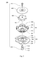
- Fig. 2 is an exploded view showing the adjusting device 100 of Fig. 1
- Fig. 3 is another exploded view showing the adjusting device 100 of Fig. 1
- Fig. 4 is a cross-sectional view showing a releasing unit 400 located in a first position of the adjusting device 100 of Fig. 1
- Fig. 5 is a cross-sectional view showing the releasing unit 400 located in a second position of the adjusting device 100 of Fig. 1 .
- the adjusting device 100 for tightening or loosening a lace is provided in the present disclosure.
- the adjusting device 100 includes a base 200, a knob 300 and a releasing unit 400.
- the base 200 includes an accommodating space 210 and at least one stopping member 220.
- the accommodating space 210 includes two holes 230, and the accommodating space 210 can be communicated with an ambience through the two holes 230.
- the base 200 has a circular wall 240 surrounding the accommodating space 210.
- the stopping member 220 includes a plurality of claws corresponding to a central axis of the base 200, and a through hole 250 is formed in a center of the stopping member 220.
- the knob 300 is assembled above the accommodating space 210.
- a hole 330 is formed in a center of the knob 300, and an outer side of the knob 300 has grains for rotating by a user.
- the knob 300 includes an annular track 310 corresponding to the two holes 230 for winding a lace (not shown).
- the annular track 310 is located inside the circular wall 240.
- the knob 300 includes a plurality of annular teeth 320, and the annular teeth 320 are located above the circular wall 240.
- An engaging space 321 is formed between the annular teeth 320.
- four concave grooves 301 are formed on the outer side of the knob 300. The four concave grooves 301 are provided for allowing the user's finger to insert thereinto for operation.
- the releasing unit 400 is disposed in the accommodating space 210 and the engaging space 321 of the knob 300.
- the releasing unit 400 is formed by sequentially assembling an axial member 410, an annular member 420 and a moving member 430 via a screw 411.
- a plurality of elastic arms 431 is surroundingly disposed on the annular member 420.
- the axial member 410 passes through the through hole 250, the hole 330, the annular member 420 and the moving member 430, and then is fastened by the screw 411.
- the axial member 410 includes a first limiting portion 412, a second limiting portion 413 and an intermittent sliding portion 414.
- the moving member 430 is located above and fully covers the engaging space 321.
- the moving member 430 is stacked on the knob 300, and the moving member 430 is corresponding to the knob 300 in shape.
- the intermittent sliding portion 414 allows the stopping member 220 to pass therethrough.
- the stopping member 220 is positioned by the first limiting portion 412
- the releasing unit 400 is located in a first portion, and the elastic arm 431 is engaged with one of the annular teeth 320, thus limiting a rotation of the knob 300 towards a releasing direction.
- the stopping member 220 is positioned by the second limiting portion 413, the releasing unit 400 is located in a second position, and the elastic arm 431 is separated from the annular teeth 320, and thus the lace can be fully loosened by the knob 300.
- the elastic arm 431 can enter the engaging space 321 along an axial direction and can be engaged with the annular teeth 320 or separated from the annular teeth 320.
- a user may move the moving member 430 for raising or lowering the moving member 430 through the concave groove 301, thereby controlling the releasing unit 400 to be located in the first position or the second position. Therefore, the adjusting device 100 can tighten or loosen the lace without equipping with an elastic member that used in the conventional adjusting device, and is easily assembled and operated.
- Fig. 7 is an exploded view showing an adjusting device according to another embodiment of the present disclosure
- Fig. 8 is another exploded view showing the adjusting device of Fig. 7
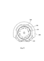
- Fig. 9 is a cross-sectional view showing a releasing unit 700 located in a first position of the adjusting device of Fig. 7
- Fig. 10 is a cross-sectional view showing the releasing unit 700 located in a second position of the adjusting device of Fig. 7
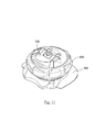
- Fig. 11 is a perspective view showing the adjusting device of Fig. 7 .
- the adjusting device includes a base 500, a knob 600 and a releasing unit 700.
- the base 500 includes an accommodating space 510.
- An axial member 520 is disposed in the center of the accommodating space 510, and the accommodating space 510 has two holes 530 that can be communicated with an ambience.
- the knob 600 is pivotally disposed in the accommodating space 510 and can be rotated by a user's finger.
- the knob 600 includes an annular track 610 that is corresponding to the two holes 530 for winding a lace (not shown).
- the knob 600 includes a plurality of annular teeth 620.
- the releasing unit 700 is assembled in the accommodating space 510 and the knob 600.
- the releasing unit 700 includes a stopping base 710, a moving member 720, a pulling arm 730 and a cover 740.
- the stopping base 710 is surrounded by a plurality of stopping members 711.
- the moving member 720 uses two pivot portions 721 to pass through the stopping base 710, and the pivot portions 721 are pivoted at one end of the pulling arm 730 by a pivot axis 7211 (the other end of the pulling arm 730 is used for operation by a user), and thus the pulling arm 730 is assembled on the stopping base 710.
- the pulling arm 730 includes a protruding portion 731 for resisting and pushing a supporting surface 712 of the stopping base 710.
- the protruding portion 731 of the pulling arm 730 pushes the supporting surface 712 to raise the moving member 720.
- the moving member 720 includes four elastic arms 722, four first limiting portions 723 and four second limiting portion 724.
- An intermittent sliding portion 725 is located between each of the first limiting portions 723 and each of the second limiting portions 724. While a preliminary force is exerted, the intermittent sliding portion 725 allows the stopping member 711 to pass therethrough.
- the stopping member 711 is positioned by the first limiting portion 723
- the releasing unit 700 is located in a first position, and each of the elastic arms 722 is engaged with the one of the annular teeth 620.
- the releasing unit 700 When the stopping member 711 is positioned by the second limiting portion 724 (the protruding portion 731 of the pulling arm 730 pushes the supporting surface 712 to raise the moving member 720), the releasing unit 700 is located in a second position, and each of the elastic arms 722 is separated from the annular teeth 620.
- the cover 740 is fixed on the stopping base 710, and a bulge 741 is formed on the cover 740. The bulge 741 can be pushed by a surface 732 of the pulling arm 730, thereby assisting to raise the moving member 720.
- a screw 800 passes through the stopping base 710, the moving member 720 and the cover 740 and is screwed to the axial member 520.
- Fig. 12 is an exploded view showing another example of the adjusting device of Fig. 7 .
- the protruding portion 731 of the pulling arm 730 is replaced by an arc portion 733 for pushing the supporting surface 712 on the stopping base 710, thereby raising the moving member 720.
- the adjusting device of the present disclosure has a tightening or loosening function without equipping with an elastic member (e.g. the elastic plate or the spring used in the conventional adjusting device), and thus the failure rate and the damage caused by the repeating usage of the elastic member can be reduced.
- the elastic arm 431 can freely enter the engaging space 321, and can be engaged with the annular teeth 320 or separated from the annular teeth 320.
- the aforementioned mechanism can include various variants, and therefore, generic terms such as "a first assembling portion" and "a second assembling portion” are used for descripting the aforementioned mechanism.
- an axial combination of an elastic arm to annular teeth an axial combination of annular teeth to annular teeth, a radial combination of annular teeth to annular teeth, a magnetic combination or a jamming combination can be possibly utilized.
- the details regarding the combination of the first assembling portion and the second assembling portion are similar to the aforementioned embodiments of the present disclosure, and are not repeated herein.
- the adjusting device of the present disclosure can be applied to various products, such as shoes, clothes or other products that need to be tightened by laces.
Landscapes
- Footwear And Its Accessory, Manufacturing Method And Apparatuses (AREA)
- Orthopedics, Nursing, And Contraception (AREA)
- Purses, Travelling Bags, Baskets, Or Suitcases (AREA)
- Buckles (AREA)
Applications Claiming Priority (1)
| Application Number | Priority Date | Filing Date | Title |
|---|---|---|---|
| TW103105138A TWI561453B (en) | 2014-02-17 | 2014-02-17 | A device for tightening and loosening a lace |
Publications (2)
| Publication Number | Publication Date |
|---|---|
| EP2907406A1 true EP2907406A1 (fr) | 2015-08-19 |
| EP2907406B1 EP2907406B1 (fr) | 2018-02-28 |
Family
ID=52273021
Family Applications (1)
| Application Number | Title | Priority Date | Filing Date |
|---|---|---|---|
| EP15150050.1A Active EP2907406B1 (fr) | 2014-02-17 | 2015-01-02 | Dispositif de réglage pour serrer ou desserrer un lacet |
Country Status (8)
| Country | Link |
|---|---|
| US (2) | US9408438B2 (fr) |
| EP (1) | EP2907406B1 (fr) |
| JP (1) | JP6204389B2 (fr) |
| KR (2) | KR101852661B1 (fr) |
| CN (1) | CN104839942B (fr) |
| ES (1) | ES2663321T3 (fr) |
| NO (1) | NO2907406T3 (fr) |
| TW (1) | TWI561453B (fr) |
Cited By (1)
| Publication number | Priority date | Publication date | Assignee | Title |
|---|---|---|---|---|
| CN104003064A (zh) * | 2013-02-26 | 2014-08-27 | 国基电子(上海)有限公司 | 束线装置 |
Families Citing this family (32)
| Publication number | Priority date | Publication date | Assignee | Title |
|---|---|---|---|---|
| ITTV20130045A1 (it) * | 2013-04-09 | 2014-10-10 | Northwave Srl | Dispositivo di serraggio |
| JP6105404B2 (ja) * | 2013-06-18 | 2017-03-29 | 株式会社ジャパーナ | 靴紐巻取用リール |
| JP6087219B2 (ja) | 2013-06-18 | 2017-03-01 | 株式会社ジャパーナ | 靴紐巻取装置 |
| CN105159393B (zh) * | 2015-09-24 | 2017-06-20 | 惠州市富池精工股份有限公司 | 一种单向止转的旋钮 |
| CN106919220B (zh) * | 2015-12-25 | 2018-06-05 | 陈金柱 | 紧固装置 |
| TWI576060B (zh) * | 2015-12-25 | 2017-04-01 | 陳金柱 | 緊固裝置 |
| US10893660B2 (en) | 2016-04-19 | 2021-01-19 | Kevin A. Hill | Length control system and method |
| US9943071B2 (en) * | 2016-04-19 | 2018-04-17 | Kevin A Hill | Length control system and method |
| CN106428993B (zh) * | 2016-07-29 | 2019-03-08 | 温州职业技术学院 | 一种捆扎包装装置 |
| JP6882827B2 (ja) | 2016-08-10 | 2021-06-02 | 株式会社アルペン | 巻取装置 |
| US10575590B2 (en) * | 2016-10-25 | 2020-03-03 | James Rankin | No bow lace loopers |
| US11607014B2 (en) | 2016-11-11 | 2023-03-21 | Chin-Chu Chen | Fastening device and lace assembling method |
| US11751634B2 (en) | 2016-11-11 | 2023-09-12 | Chin-Chu Chen | Fastening device and lace assembling method |
| ES2941773T3 (es) * | 2016-11-11 | 2023-05-25 | Chen Chin Chu | Dispositivo de fijación y método de ensamblaje del mismo |
| KR101837194B1 (ko) * | 2016-12-30 | 2018-03-13 | 소윤서 | 줄 길이 조절장치 |
| US9918516B1 (en) * | 2017-02-08 | 2018-03-20 | LNZ Products Inc. | Lace 'N lock shoe tying system |
| CN114680426A (zh) * | 2017-03-01 | 2022-07-01 | Boa科技股份有限公司 | 基于卷轴的拉紧装置 |
| US11707115B2 (en) | 2017-05-31 | 2023-07-25 | Nike, Inc. | Automated footwear lacing systems, devices, and techniques |
| CN109330086B (zh) * | 2018-10-15 | 2020-08-25 | 温州市金烈马鞋业有限公司 | 一种可收缩鞋面的休闲鞋及其穿戴方法 |
| US12207706B2 (en) * | 2018-10-30 | 2025-01-28 | Chin-Chu Chen | Fastening device |
| CN111115389B (zh) * | 2018-10-30 | 2022-04-05 | 陈金柱 | 紧固装置 |
| WO2020156368A1 (fr) * | 2019-01-30 | 2020-08-06 | 陈金柱 | Procédé d'installation pour dispositif de fixation et mécanisme de formation de trou d'installation |
| TWI694216B (zh) * | 2019-04-25 | 2020-05-21 | 陳金柱 | 緊固裝置 |
| US12137773B2 (en) | 2019-04-25 | 2024-11-12 | Chin-Chu Chen | Fastening device |
| US12185796B2 (en) | 2019-06-05 | 2025-01-07 | Garrett Ray Hurley | Tool operated adjustment devices, fit systems, and line tensioning systems |
| DE102019217036A1 (de) * | 2019-11-05 | 2021-05-06 | Fidlock Gmbh | Verschlussvorrichtung mit einem Drehelement |
| CN114906374A (zh) * | 2021-02-09 | 2022-08-16 | 陈臆霙 | 紧固装置及系线收放方法 |
| EP4144250A1 (fr) * | 2021-07-19 | 2023-03-08 | Shishi Senke Intelligent Technology Co., Ltd. | Enrouleur de câble rotatif à poussée-traction et chaussures |
| CN115153157A (zh) * | 2022-08-03 | 2022-10-11 | 李惠卿 | 一种系带装置、系带物以及系带方法 |
| CN115744503B (zh) * | 2022-11-21 | 2025-11-28 | 河源市大邦科枝有限公司 | 一种正反转松紧系绳装置 |
| US12516718B2 (en) * | 2023-08-02 | 2026-01-06 | Tool Manufacturing, Inc. | Dial drive fit system |
| CN120379917B (zh) * | 2024-02-01 | 2026-02-10 | 深圳市爱旋科技有限公司 | 可微调绳线收放装置及物品 |
Citations (2)
| Publication number | Priority date | Publication date | Assignee | Title |
|---|---|---|---|---|
| JPH07208A (ja) | 1991-12-20 | 1995-01-06 | Kobatsuku:Kk | 靴紐締付具 |
| DE202010000354U1 (de) * | 2009-03-12 | 2010-06-17 | Chen, Chin-Chu, Lung-Ching Hsiang | Schnur-Sicherungsvorrichtung |
Family Cites Families (19)
| Publication number | Priority date | Publication date | Assignee | Title |
|---|---|---|---|---|
| US5934599A (en) * | 1997-08-22 | 1999-08-10 | Hammerslag; Gary R. | Footwear lacing system |
| US20060156517A1 (en) * | 1997-08-22 | 2006-07-20 | Hammerslag Gary R | Reel based closure system |
| US7174575B1 (en) * | 2004-07-26 | 2007-02-13 | E.D. Bullard Company | Ratchet mechanism for the headband of protective headgear used in high temperature environments |
| KR100598627B1 (ko) * | 2005-06-27 | 2006-07-13 | 주식회사 신경 | 신발끈 조임기 |
| US7367522B2 (en) * | 2005-10-14 | 2008-05-06 | Chin Chu Chen | String fastening device |
| EP2378911B1 (fr) * | 2008-11-21 | 2014-05-21 | Boa Technology, Inc. | Système de laçage a enrouleur |
| KR20100009337U (ko) * | 2009-03-12 | 2010-09-27 | 친-추 첸 | 스트링 고정 장치 |
| US8245371B2 (en) * | 2009-04-01 | 2012-08-21 | Chin Chu Chen | String securing device |
| TW201127310A (en) * | 2010-02-11 | 2011-08-16 | jin-zhu Chen | Step-less finetuning buckle |
| KR102566159B1 (ko) * | 2010-04-30 | 2023-08-16 | 보아 테크놀러지, 인크. | 릴 기반 끈 조임 시스템 |
| KR101040372B1 (ko) * | 2010-07-21 | 2011-06-10 | 소윤서 | 줄 길이 조절장치 |
| US8353087B2 (en) * | 2011-03-07 | 2013-01-15 | Chin-Chu Chen | Closure device |
| KR101099458B1 (ko) * | 2011-07-25 | 2011-12-27 | 주식회사 신경 | 신발끈 조임장치 |
| US9101181B2 (en) * | 2011-10-13 | 2015-08-11 | Boa Technology Inc. | Reel-based lacing system |
| WO2014074645A2 (fr) * | 2012-11-06 | 2014-05-15 | Boa Technology Inc. | Dispositifs et procédés de réglage de l'ajustement de chaussures |
| CA2874232C (fr) * | 2012-11-30 | 2018-02-27 | Puma SE | Dispositif de fermeture rotatif pour chaussure |
| CN104003064B (zh) * | 2013-02-26 | 2016-06-29 | 国基电子(上海)有限公司 | 束线装置 |
| TWM471175U (zh) * | 2013-09-11 | 2014-02-01 | Chin-Chu Chen | 帶體收放裝置 |
| FR3023455B1 (fr) * | 2014-07-08 | 2016-08-26 | Mavic Sas | Dispositif d'enroulement et de blocage a cliquet d'un lacet de serrage |
-
2014
- 2014-02-17 TW TW103105138A patent/TWI561453B/zh active
- 2014-11-03 CN CN201410610677.7A patent/CN104839942B/zh active Active
- 2014-12-29 US US14/585,153 patent/US9408438B2/en active Active
-
2015
- 2015-01-02 ES ES15150050.1T patent/ES2663321T3/es active Active
- 2015-01-02 EP EP15150050.1A patent/EP2907406B1/fr active Active
- 2015-01-02 NO NO15150050A patent/NO2907406T3/no unknown
- 2015-01-19 KR KR1020150008540A patent/KR101852661B1/ko active Active
- 2015-02-03 JP JP2015019400A patent/JP6204389B2/ja active Active
-
2016
- 2016-06-20 US US15/187,765 patent/US9622544B2/en active Active
-
2018
- 2018-02-12 KR KR1020180017089A patent/KR101852744B1/ko active Active
Patent Citations (3)
| Publication number | Priority date | Publication date | Assignee | Title |
|---|---|---|---|---|
| JPH07208A (ja) | 1991-12-20 | 1995-01-06 | Kobatsuku:Kk | 靴紐締付具 |
| DE202010000354U1 (de) * | 2009-03-12 | 2010-06-17 | Chen, Chin-Chu, Lung-Ching Hsiang | Schnur-Sicherungsvorrichtung |
| TWI374016B (fr) | 2009-03-12 | 2012-10-11 |
Cited By (2)
| Publication number | Priority date | Publication date | Assignee | Title |
|---|---|---|---|---|
| CN104003064A (zh) * | 2013-02-26 | 2014-08-27 | 国基电子(上海)有限公司 | 束线装置 |
| CN104003064B (zh) * | 2013-02-26 | 2016-06-29 | 国基电子(上海)有限公司 | 束线装置 |
Also Published As
| Publication number | Publication date |
|---|---|
| ES2663321T3 (es) | 2018-04-12 |
| EP2907406B1 (fr) | 2018-02-28 |
| US9408438B2 (en) | 2016-08-09 |
| KR101852661B1 (ko) | 2018-06-11 |
| TWI561453B (en) | 2016-12-11 |
| NO2907406T3 (fr) | 2018-07-28 |
| KR20180018644A (ko) | 2018-02-21 |
| CN104839942B (zh) | 2017-08-15 |
| US20160286902A1 (en) | 2016-10-06 |
| CN104839942A (zh) | 2015-08-19 |
| JP2015150426A (ja) | 2015-08-24 |
| JP6204389B2 (ja) | 2017-09-27 |
| KR20150097389A (ko) | 2015-08-26 |
| TW201532931A (zh) | 2015-09-01 |
| KR101852744B1 (ko) | 2018-04-27 |
| US9622544B2 (en) | 2017-04-18 |
| US20150230560A1 (en) | 2015-08-20 |
Similar Documents
| Publication | Publication Date | Title |
|---|---|---|
| US9622544B2 (en) | Adjusting device for tightening or loosening lace | |
| EP3189743B1 (fr) | Appareil et procédé de serrage et de desserrage de lacet. | |
| US8235321B2 (en) | Stepless fastening device | |
| CA2876000C (fr) | Dispositif d'enroulement de lacets | |
| KR101249420B1 (ko) | 와이어 조임장치 | |
| KR102297325B1 (ko) | 릴 기반 폐쇄 장치 및 그에 따른 방법 | |
| CN105982392B (zh) | 绳索调整扣具 | |
| JP2016539750A (ja) | 紐の締緩手段 | |
| TWI513423B (zh) | 帶體收放裝置及其收放方法 | |
| JP7546334B1 (ja) | 紐用リール | |
| KR20160131296A (ko) | 커버 교체가 가능한 와이어 조임장치 | |
| JP3241783U (ja) | 正逆転紐締緩手段 | |
| JP2022019790A (ja) | ひも締緩装置 | |
| JP2020018890A (ja) | ひも締緩装置 | |
| KR20170055454A (ko) | 커버 교체가 가능한 와이어 조임장치 | |
| KR20200119618A (ko) | 와이어 조임장치 | |
| KR20100102074A (ko) | 제자리 뛰기 운동기구 | |
| KR20130080199A (ko) | 아이젠 조립체 및 이를 구비하는 신발 | |
| KR101763868B1 (ko) | 와이어 조임장치 | |
| WO2020079139A1 (fr) | Dispositif de fixation destiné à des chaussures et articles techniques | |
| JP2019017962A (ja) | 靴ひもの締め具合調整器具 |
Legal Events
| Date | Code | Title | Description |
|---|---|---|---|
| PUAI | Public reference made under article 153(3) epc to a published international application that has entered the european phase |
Free format text: ORIGINAL CODE: 0009012 |
|
| AK | Designated contracting states |
Kind code of ref document: A1 Designated state(s): AL AT BE BG CH CY CZ DE DK EE ES FI FR GB GR HR HU IE IS IT LI LT LU LV MC MK MT NL NO PL PT RO RS SE SI SK SM TR |
|
| AX | Request for extension of the european patent |
Extension state: BA ME |
|
| 17P | Request for examination filed |
Effective date: 20160219 |
|
| RBV | Designated contracting states (corrected) |
Designated state(s): AL AT BE BG CH CY CZ DE DK EE ES FI FR GB GR HR HU IE IS IT LI LT LU LV MC MK MT NL NO PL PT RO RS SE SI SK SM TR |
|
| GRAP | Despatch of communication of intention to grant a patent |
Free format text: ORIGINAL CODE: EPIDOSNIGR1 |
|
| STAA | Information on the status of an ep patent application or granted ep patent |
Free format text: STATUS: GRANT OF PATENT IS INTENDED |
|
| INTG | Intention to grant announced |
Effective date: 20170913 |
|
| GRAS | Grant fee paid |
Free format text: ORIGINAL CODE: EPIDOSNIGR3 |
|
| GRAA | (expected) grant |
Free format text: ORIGINAL CODE: 0009210 |
|
| STAA | Information on the status of an ep patent application or granted ep patent |
Free format text: STATUS: THE PATENT HAS BEEN GRANTED |
|
| AK | Designated contracting states |
Kind code of ref document: B1 Designated state(s): AL AT BE BG CH CY CZ DE DK EE ES FI FR GB GR HR HU IE IS IT LI LT LU LV MC MK MT NL NO PL PT RO RS SE SI SK SM TR |
|
| REG | Reference to a national code |
Ref country code: GB Ref legal event code: FG4D Ref country code: CH Ref legal event code: EP |
|
| REG | Reference to a national code |
Ref country code: AT Ref legal event code: REF Ref document number: 973172 Country of ref document: AT Kind code of ref document: T Effective date: 20180315 |
|
| REG | Reference to a national code |
Ref country code: IE Ref legal event code: FG4D |
|
| REG | Reference to a national code |
Ref country code: DE Ref legal event code: R096 Ref document number: 602015008210 Country of ref document: DE |
|
| REG | Reference to a national code |
Ref country code: ES Ref legal event code: FG2A Ref document number: 2663321 Country of ref document: ES Kind code of ref document: T3 Effective date: 20180412 |
|
| REG | Reference to a national code |
Ref country code: CH Ref legal event code: NV Representative=s name: LANGPATENT ANWALTSKANZLEI IP LAW FIRM, CH |
|
| REG | Reference to a national code |
Ref country code: NL Ref legal event code: FP |
|
| REG | Reference to a national code |
Ref country code: NO Ref legal event code: T2 Effective date: 20180228 |
|
| REG | Reference to a national code |
Ref country code: LT Ref legal event code: MG4D |
|
| PG25 | Lapsed in a contracting state [announced via postgrant information from national office to epo] |
Ref country code: HR Free format text: LAPSE BECAUSE OF FAILURE TO SUBMIT A TRANSLATION OF THE DESCRIPTION OR TO PAY THE FEE WITHIN THE PRESCRIBED TIME-LIMIT Effective date: 20180228 Ref country code: CY Free format text: LAPSE BECAUSE OF FAILURE TO SUBMIT A TRANSLATION OF THE DESCRIPTION OR TO PAY THE FEE WITHIN THE PRESCRIBED TIME-LIMIT Effective date: 20180228 Ref country code: FI Free format text: LAPSE BECAUSE OF FAILURE TO SUBMIT A TRANSLATION OF THE DESCRIPTION OR TO PAY THE FEE WITHIN THE PRESCRIBED TIME-LIMIT Effective date: 20180228 Ref country code: LT Free format text: LAPSE BECAUSE OF FAILURE TO SUBMIT A TRANSLATION OF THE DESCRIPTION OR TO PAY THE FEE WITHIN THE PRESCRIBED TIME-LIMIT Effective date: 20180228 |
|
| PG25 | Lapsed in a contracting state [announced via postgrant information from national office to epo] |
Ref country code: SE Free format text: LAPSE BECAUSE OF FAILURE TO SUBMIT A TRANSLATION OF THE DESCRIPTION OR TO PAY THE FEE WITHIN THE PRESCRIBED TIME-LIMIT Effective date: 20180228 Ref country code: LV Free format text: LAPSE BECAUSE OF FAILURE TO SUBMIT A TRANSLATION OF THE DESCRIPTION OR TO PAY THE FEE WITHIN THE PRESCRIBED TIME-LIMIT Effective date: 20180228 Ref country code: RS Free format text: LAPSE BECAUSE OF FAILURE TO SUBMIT A TRANSLATION OF THE DESCRIPTION OR TO PAY THE FEE WITHIN THE PRESCRIBED TIME-LIMIT Effective date: 20180228 Ref country code: BG Free format text: LAPSE BECAUSE OF FAILURE TO SUBMIT A TRANSLATION OF THE DESCRIPTION OR TO PAY THE FEE WITHIN THE PRESCRIBED TIME-LIMIT Effective date: 20180528 Ref country code: GR Free format text: LAPSE BECAUSE OF FAILURE TO SUBMIT A TRANSLATION OF THE DESCRIPTION OR TO PAY THE FEE WITHIN THE PRESCRIBED TIME-LIMIT Effective date: 20180529 |
|
| PG25 | Lapsed in a contracting state [announced via postgrant information from national office to epo] |
Ref country code: RO Free format text: LAPSE BECAUSE OF FAILURE TO SUBMIT A TRANSLATION OF THE DESCRIPTION OR TO PAY THE FEE WITHIN THE PRESCRIBED TIME-LIMIT Effective date: 20180228 Ref country code: EE Free format text: LAPSE BECAUSE OF FAILURE TO SUBMIT A TRANSLATION OF THE DESCRIPTION OR TO PAY THE FEE WITHIN THE PRESCRIBED TIME-LIMIT Effective date: 20180228 Ref country code: PL Free format text: LAPSE BECAUSE OF FAILURE TO SUBMIT A TRANSLATION OF THE DESCRIPTION OR TO PAY THE FEE WITHIN THE PRESCRIBED TIME-LIMIT Effective date: 20180228 Ref country code: AL Free format text: LAPSE BECAUSE OF FAILURE TO SUBMIT A TRANSLATION OF THE DESCRIPTION OR TO PAY THE FEE WITHIN THE PRESCRIBED TIME-LIMIT Effective date: 20180228 |
|
| REG | Reference to a national code |
Ref country code: DE Ref legal event code: R097 Ref document number: 602015008210 Country of ref document: DE |
|
| PG25 | Lapsed in a contracting state [announced via postgrant information from national office to epo] |
Ref country code: SM Free format text: LAPSE BECAUSE OF FAILURE TO SUBMIT A TRANSLATION OF THE DESCRIPTION OR TO PAY THE FEE WITHIN THE PRESCRIBED TIME-LIMIT Effective date: 20180228 Ref country code: DK Free format text: LAPSE BECAUSE OF FAILURE TO SUBMIT A TRANSLATION OF THE DESCRIPTION OR TO PAY THE FEE WITHIN THE PRESCRIBED TIME-LIMIT Effective date: 20180228 Ref country code: SK Free format text: LAPSE BECAUSE OF FAILURE TO SUBMIT A TRANSLATION OF THE DESCRIPTION OR TO PAY THE FEE WITHIN THE PRESCRIBED TIME-LIMIT Effective date: 20180228 |
|
| PLBE | No opposition filed within time limit |
Free format text: ORIGINAL CODE: 0009261 |
|
| STAA | Information on the status of an ep patent application or granted ep patent |
Free format text: STATUS: NO OPPOSITION FILED WITHIN TIME LIMIT |
|
| 26N | No opposition filed |
Effective date: 20181129 |
|
| PG25 | Lapsed in a contracting state [announced via postgrant information from national office to epo] |
Ref country code: SI Free format text: LAPSE BECAUSE OF FAILURE TO SUBMIT A TRANSLATION OF THE DESCRIPTION OR TO PAY THE FEE WITHIN THE PRESCRIBED TIME-LIMIT Effective date: 20180228 |
|
| PG25 | Lapsed in a contracting state [announced via postgrant information from national office to epo] |
Ref country code: MC Free format text: LAPSE BECAUSE OF FAILURE TO SUBMIT A TRANSLATION OF THE DESCRIPTION OR TO PAY THE FEE WITHIN THE PRESCRIBED TIME-LIMIT Effective date: 20180228 |
|
| PG25 | Lapsed in a contracting state [announced via postgrant information from national office to epo] |
Ref country code: LU Free format text: LAPSE BECAUSE OF NON-PAYMENT OF DUE FEES Effective date: 20190102 |
|
| REG | Reference to a national code |
Ref country code: BE Ref legal event code: MM Effective date: 20190131 |
|
| REG | Reference to a national code |
Ref country code: IE Ref legal event code: MM4A |
|
| PG25 | Lapsed in a contracting state [announced via postgrant information from national office to epo] |
Ref country code: BE Free format text: LAPSE BECAUSE OF NON-PAYMENT OF DUE FEES Effective date: 20190131 |
|
| PG25 | Lapsed in a contracting state [announced via postgrant information from national office to epo] |
Ref country code: IE Free format text: LAPSE BECAUSE OF NON-PAYMENT OF DUE FEES Effective date: 20190102 |
|
| PG25 | Lapsed in a contracting state [announced via postgrant information from national office to epo] |
Ref country code: TR Free format text: LAPSE BECAUSE OF FAILURE TO SUBMIT A TRANSLATION OF THE DESCRIPTION OR TO PAY THE FEE WITHIN THE PRESCRIBED TIME-LIMIT Effective date: 20180228 |
|
| PG25 | Lapsed in a contracting state [announced via postgrant information from national office to epo] |
Ref country code: PT Free format text: LAPSE BECAUSE OF FAILURE TO SUBMIT A TRANSLATION OF THE DESCRIPTION OR TO PAY THE FEE WITHIN THE PRESCRIBED TIME-LIMIT Effective date: 20180628 Ref country code: MT Free format text: LAPSE BECAUSE OF NON-PAYMENT OF DUE FEES Effective date: 20190102 |
|
| PG25 | Lapsed in a contracting state [announced via postgrant information from national office to epo] |
Ref country code: IS Free format text: LAPSE BECAUSE OF FAILURE TO SUBMIT A TRANSLATION OF THE DESCRIPTION OR TO PAY THE FEE WITHIN THE PRESCRIBED TIME-LIMIT Effective date: 20180628 |
|
| PG25 | Lapsed in a contracting state [announced via postgrant information from national office to epo] |
Ref country code: HU Free format text: LAPSE BECAUSE OF FAILURE TO SUBMIT A TRANSLATION OF THE DESCRIPTION OR TO PAY THE FEE WITHIN THE PRESCRIBED TIME-LIMIT; INVALID AB INITIO Effective date: 20150102 |
|
| PG25 | Lapsed in a contracting state [announced via postgrant information from national office to epo] |
Ref country code: MK Free format text: LAPSE BECAUSE OF FAILURE TO SUBMIT A TRANSLATION OF THE DESCRIPTION OR TO PAY THE FEE WITHIN THE PRESCRIBED TIME-LIMIT Effective date: 20180228 |
|
| REG | Reference to a national code |
Ref country code: AT Ref legal event code: UEP Ref document number: 973172 Country of ref document: AT Kind code of ref document: T Effective date: 20180228 |
|
| PGFP | Annual fee paid to national office [announced via postgrant information from national office to epo] |
Ref country code: GB Payment date: 20251218 Year of fee payment: 12 |
|
| PGFP | Annual fee paid to national office [announced via postgrant information from national office to epo] |
Ref country code: NL Payment date: 20251225 Year of fee payment: 12 Ref country code: FR Payment date: 20251222 Year of fee payment: 12 |
|
| PGFP | Annual fee paid to national office [announced via postgrant information from national office to epo] |
Ref country code: CZ Payment date: 20251223 Year of fee payment: 12 |
|
| REG | Reference to a national code |
Ref country code: CH Ref legal event code: U11 Free format text: ST27 STATUS EVENT CODE: U-0-0-U10-U11 (AS PROVIDED BY THE NATIONAL OFFICE) Effective date: 20260201 |
|
| PGFP | Annual fee paid to national office [announced via postgrant information from national office to epo] |
Ref country code: ES Payment date: 20260212 Year of fee payment: 12 |
|
| PGFP | Annual fee paid to national office [announced via postgrant information from national office to epo] |
Ref country code: DE Payment date: 20251224 Year of fee payment: 12 Ref country code: NO Payment date: 20260109 Year of fee payment: 12 |
|
| PGFP | Annual fee paid to national office [announced via postgrant information from national office to epo] |
Ref country code: AT Payment date: 20251230 Year of fee payment: 12 |
|
| PGFP | Annual fee paid to national office [announced via postgrant information from national office to epo] |
Ref country code: IT Payment date: 20251230 Year of fee payment: 12 |
|
| PGFP | Annual fee paid to national office [announced via postgrant information from national office to epo] |
Ref country code: CH Payment date: 20260201 Year of fee payment: 12 |