EP2907535A2 - Spritzenartige Pumpe - Google Patents
Spritzenartige Pumpe Download PDFInfo
- Publication number
- EP2907535A2 EP2907535A2 EP15154808.8A EP15154808A EP2907535A2 EP 2907535 A2 EP2907535 A2 EP 2907535A2 EP 15154808 A EP15154808 A EP 15154808A EP 2907535 A2 EP2907535 A2 EP 2907535A2
- Authority
- EP
- European Patent Office
- Prior art keywords
- skin
- cannula
- barrel
- piston
- pump
- Prior art date
- Legal status (The legal status is an assumption and is not a legal conclusion. Google has not performed a legal analysis and makes no representation as to the accuracy of the status listed.)
- Granted
Links
Images

Classifications
-
- A—HUMAN NECESSITIES
- A61—MEDICAL OR VETERINARY SCIENCE; HYGIENE
- A61M—DEVICES FOR INTRODUCING MEDIA INTO, OR ONTO, THE BODY; DEVICES FOR TRANSDUCING BODY MEDIA OR FOR TAKING MEDIA FROM THE BODY; DEVICES FOR PRODUCING OR ENDING SLEEP OR STUPOR
- A61M5/00—Devices for bringing media into the body in a subcutaneous, intra-vascular or intramuscular way; Accessories therefor, e.g. filling or cleaning devices, arm-rests
- A61M5/14—Infusion devices, e.g. infusing by gravity; Blood infusion; Accessories therefor
- A61M5/142—Pressure infusion, e.g. using pumps
- A61M5/14244—Pressure infusion, e.g. using pumps adapted to be carried by the patient, e.g. portable on the body
- A61M5/14248—Pressure infusion, e.g. using pumps adapted to be carried by the patient, e.g. portable on the body of the skin patch type
-
- A—HUMAN NECESSITIES
- A61—MEDICAL OR VETERINARY SCIENCE; HYGIENE
- A61M—DEVICES FOR INTRODUCING MEDIA INTO, OR ONTO, THE BODY; DEVICES FOR TRANSDUCING BODY MEDIA OR FOR TAKING MEDIA FROM THE BODY; DEVICES FOR PRODUCING OR ENDING SLEEP OR STUPOR
- A61M5/00—Devices for bringing media into the body in a subcutaneous, intra-vascular or intramuscular way; Accessories therefor, e.g. filling or cleaning devices, arm-rests
- A61M5/14—Infusion devices, e.g. infusing by gravity; Blood infusion; Accessories therefor
- A61M5/142—Pressure infusion, e.g. using pumps
- A61M5/14212—Pumping with an aspiration and an expulsion action
- A61M5/14216—Reciprocating piston type
-
- A—HUMAN NECESSITIES
- A61—MEDICAL OR VETERINARY SCIENCE; HYGIENE
- A61M—DEVICES FOR INTRODUCING MEDIA INTO, OR ONTO, THE BODY; DEVICES FOR TRANSDUCING BODY MEDIA OR FOR TAKING MEDIA FROM THE BODY; DEVICES FOR PRODUCING OR ENDING SLEEP OR STUPOR
- A61M5/00—Devices for bringing media into the body in a subcutaneous, intra-vascular or intramuscular way; Accessories therefor, e.g. filling or cleaning devices, arm-rests
- A61M5/14—Infusion devices, e.g. infusing by gravity; Blood infusion; Accessories therefor
- A61M5/142—Pressure infusion, e.g. using pumps
- A61M5/145—Pressure infusion, e.g. using pumps using pressurised reservoirs, e.g. pressurised by means of pistons
- A61M5/1452—Pressure infusion, e.g. using pumps using pressurised reservoirs, e.g. pressurised by means of pistons pressurised by means of pistons
-
- A—HUMAN NECESSITIES
- A61—MEDICAL OR VETERINARY SCIENCE; HYGIENE
- A61B—DIAGNOSIS; SURGERY; IDENTIFICATION
- A61B5/00—Measuring for diagnostic purposes; Identification of persons
- A61B5/0002—Remote monitoring of patients using telemetry, e.g. transmission of vital signals via a communication network
- A61B5/0004—Remote monitoring of patients using telemetry, e.g. transmission of vital signals via a communication network characterised by the type of physiological signal transmitted
-
- A—HUMAN NECESSITIES
- A61—MEDICAL OR VETERINARY SCIENCE; HYGIENE
- A61B—DIAGNOSIS; SURGERY; IDENTIFICATION
- A61B5/00—Measuring for diagnostic purposes; Identification of persons
- A61B5/145—Measuring characteristics of blood in vivo, e.g. gas concentration or pH-value ; Measuring characteristics of body fluids or tissues, e.g. interstitial fluid or cerebral tissue
-
- A—HUMAN NECESSITIES
- A61—MEDICAL OR VETERINARY SCIENCE; HYGIENE
- A61B—DIAGNOSIS; SURGERY; IDENTIFICATION
- A61B5/00—Measuring for diagnostic purposes; Identification of persons
- A61B5/15—Devices for taking samples of blood
- A61B5/150007—Details
- A61B5/150206—Construction or design features not otherwise provided for; manufacturing or production; packages; sterilisation of piercing element, piercing device or sampling device
- A61B5/150229—Pumps for assisting the blood sampling
-
- A—HUMAN NECESSITIES
- A61—MEDICAL OR VETERINARY SCIENCE; HYGIENE
- A61B—DIAGNOSIS; SURGERY; IDENTIFICATION
- A61B5/00—Measuring for diagnostic purposes; Identification of persons
- A61B5/48—Other medical applications
- A61B5/4836—Diagnosis combined with treatment in closed-loop systems or methods
- A61B5/4839—Diagnosis combined with treatment in closed-loop systems or methods combined with drug delivery
-
- A—HUMAN NECESSITIES
- A61—MEDICAL OR VETERINARY SCIENCE; HYGIENE
- A61M—DEVICES FOR INTRODUCING MEDIA INTO, OR ONTO, THE BODY; DEVICES FOR TRANSDUCING BODY MEDIA OR FOR TAKING MEDIA FROM THE BODY; DEVICES FOR PRODUCING OR ENDING SLEEP OR STUPOR
- A61M5/00—Devices for bringing media into the body in a subcutaneous, intra-vascular or intramuscular way; Accessories therefor, e.g. filling or cleaning devices, arm-rests
- A61M5/14—Infusion devices, e.g. infusing by gravity; Blood infusion; Accessories therefor
- A61M5/142—Pressure infusion, e.g. using pumps
- A61M5/145—Pressure infusion, e.g. using pumps using pressurised reservoirs, e.g. pressurised by means of pistons
- A61M5/1452—Pressure infusion, e.g. using pumps using pressurised reservoirs, e.g. pressurised by means of pistons pressurised by means of pistons
- A61M5/1454—Pressure infusion, e.g. using pumps using pressurised reservoirs, e.g. pressurised by means of pistons pressurised by means of pistons spring-actuated, e.g. by a clockwork
-
- A—HUMAN NECESSITIES
- A61—MEDICAL OR VETERINARY SCIENCE; HYGIENE
- A61M—DEVICES FOR INTRODUCING MEDIA INTO, OR ONTO, THE BODY; DEVICES FOR TRANSDUCING BODY MEDIA OR FOR TAKING MEDIA FROM THE BODY; DEVICES FOR PRODUCING OR ENDING SLEEP OR STUPOR
- A61M5/00—Devices for bringing media into the body in a subcutaneous, intra-vascular or intramuscular way; Accessories therefor, e.g. filling or cleaning devices, arm-rests
- A61M5/14—Infusion devices, e.g. infusing by gravity; Blood infusion; Accessories therefor
- A61M5/168—Means for controlling media flow to the body or for metering media to the body, e.g. drip meters, counters ; Monitoring media flow to the body
- A61M5/172—Means for controlling media flow to the body or for metering media to the body, e.g. drip meters, counters ; Monitoring media flow to the body electrical or electronic
- A61M5/1723—Means for controlling media flow to the body or for metering media to the body, e.g. drip meters, counters ; Monitoring media flow to the body electrical or electronic using feedback of body parameters, e.g. blood-sugar, pressure
-
- A—HUMAN NECESSITIES
- A61—MEDICAL OR VETERINARY SCIENCE; HYGIENE
- A61M—DEVICES FOR INTRODUCING MEDIA INTO, OR ONTO, THE BODY; DEVICES FOR TRANSDUCING BODY MEDIA OR FOR TAKING MEDIA FROM THE BODY; DEVICES FOR PRODUCING OR ENDING SLEEP OR STUPOR
- A61M5/00—Devices for bringing media into the body in a subcutaneous, intra-vascular or intramuscular way; Accessories therefor, e.g. filling or cleaning devices, arm-rests
- A61M5/178—Syringes
- A61M5/31—Details
- A61M5/32—Needles; Details of needles pertaining to their connection with syringe or hub; Accessories for bringing the needle into, or holding the needle on, the body; Devices for protection of needles
- A61M5/3287—Accessories for bringing the needle into the body; Automatic needle insertion
-
- A—HUMAN NECESSITIES
- A61—MEDICAL OR VETERINARY SCIENCE; HYGIENE
- A61M—DEVICES FOR INTRODUCING MEDIA INTO, OR ONTO, THE BODY; DEVICES FOR TRANSDUCING BODY MEDIA OR FOR TAKING MEDIA FROM THE BODY; DEVICES FOR PRODUCING OR ENDING SLEEP OR STUPOR
- A61M5/00—Devices for bringing media into the body in a subcutaneous, intra-vascular or intramuscular way; Accessories therefor, e.g. filling or cleaning devices, arm-rests
- A61M5/14—Infusion devices, e.g. infusing by gravity; Blood infusion; Accessories therefor
- A61M5/142—Pressure infusion, e.g. using pumps
- A61M5/14244—Pressure infusion, e.g. using pumps adapted to be carried by the patient, e.g. portable on the body
- A61M5/14248—Pressure infusion, e.g. using pumps adapted to be carried by the patient, e.g. portable on the body of the skin patch type
- A61M2005/14252—Pressure infusion, e.g. using pumps adapted to be carried by the patient, e.g. portable on the body of the skin patch type with needle insertion means
-
- A—HUMAN NECESSITIES
- A61—MEDICAL OR VETERINARY SCIENCE; HYGIENE
- A61M—DEVICES FOR INTRODUCING MEDIA INTO, OR ONTO, THE BODY; DEVICES FOR TRANSDUCING BODY MEDIA OR FOR TAKING MEDIA FROM THE BODY; DEVICES FOR PRODUCING OR ENDING SLEEP OR STUPOR
- A61M5/00—Devices for bringing media into the body in a subcutaneous, intra-vascular or intramuscular way; Accessories therefor, e.g. filling or cleaning devices, arm-rests
- A61M5/178—Syringes
- A61M5/31—Details
- A61M5/315—Pistons; Piston-rods; Guiding, blocking or restricting the movement of the rod or piston; Appliances on the rod for facilitating dosing ; Dosing mechanisms
- A61M5/31511—Piston or piston-rod constructions, e.g. connection of piston with piston-rod
- A61M2005/31518—Piston or piston-rod constructions, e.g. connection of piston with piston-rod designed to reduce the overall size of an injection device, e.g. using flexible or pivotally connected chain-like rod members
-
- A—HUMAN NECESSITIES
- A61—MEDICAL OR VETERINARY SCIENCE; HYGIENE
- A61M—DEVICES FOR INTRODUCING MEDIA INTO, OR ONTO, THE BODY; DEVICES FOR TRANSDUCING BODY MEDIA OR FOR TAKING MEDIA FROM THE BODY; DEVICES FOR PRODUCING OR ENDING SLEEP OR STUPOR
- A61M2205/00—General characteristics of the apparatus
- A61M2205/50—General characteristics of the apparatus with microprocessors or computers
-
- A—HUMAN NECESSITIES
- A61—MEDICAL OR VETERINARY SCIENCE; HYGIENE
- A61M—DEVICES FOR INTRODUCING MEDIA INTO, OR ONTO, THE BODY; DEVICES FOR TRANSDUCING BODY MEDIA OR FOR TAKING MEDIA FROM THE BODY; DEVICES FOR PRODUCING OR ENDING SLEEP OR STUPOR
- A61M5/00—Devices for bringing media into the body in a subcutaneous, intra-vascular or intramuscular way; Accessories therefor, e.g. filling or cleaning devices, arm-rests
- A61M5/178—Syringes
- A61M5/31—Details
- A61M5/3129—Syringe barrels
Definitions
- the present invention is related with a syringe type pump according to the preamble of claim 1.
- One major field of application for this type of pumps is the injection of physiologically active fluid into a patient and/or the extraction of body fluid for diagnostic purposes.
- the pumps are usually equipped with both a contact surface for attaching to a patient's skin and a cannula for the access to the patient's tissue or vessels for introducing an injection fluid or the removal of analysis fluid.
- Injection devices are widely used in patient care but their size and complexity largely restricts their use to specialized facilities. Recently, ambulatory use of injection devices has been pioneered in diabetes care for the delivery of insulin. To achieve the necessary precision of delivery these injection devices typically use syringe pumps. The size of these devices is considerable, dictated mainly by the extended, longitudinal shape of a filled syringe with the drawn-out piston, and necessitates their wearing attached to e.g. a belt or underwear and they operate with connective barrels to a subcutaneously placed cannula leading to inconveniences and safety problems.
- Syringe pumps for such applications have barrels with a wide diameter in order to avoid an extended longitudinal footprint, but this solution has disadvantages necessitating high driving forces to inject against a considerable tissue back-pressure and most importantly because of the risk of air bubbles entering and occluding the injection cannula due to almost unavoidable relatively large dead-volumes, and unintended, relatively large bolus injections due to stick-slip effects.
- the aim of the present invention is to provide an arcuate syringe type pump which avoids the disadvantages of the state of the art devices.
- the configuration using a curved toroidal barrel combines the high precision of syringe pumps with a compact shape.
- the driving rod of the piston is guided and supported by the surface of the inner barrel wall and is preferably flexible and thus self-adapting to the inner curvature of the barrel.
- the barrel has a curvature preferentially with an arc below 180°, 150°-160° being most preferred for an optimal length/diameter ratio of the barrel for precision of dosing and which can be manufactured by standard plastics-technologies. Further, with improved individual components of the device and the co-operation of the components a desired reduction in overall size and simplification of mechanical operation is achieved. According to the invention, major problems with current devices are solved by an injection or analysis fluid removal device having the features disclosed herein below.
- the subject injection device for introducing an injection fluid into a patient through the patient's skin or through an intravenous or intraperitoneal port comprises a syringe-type pump with a barrel in form of a segment of a toroidal tube and a piston fitting tightly into the barrel which can be passed through the entire barrel actuated by drive and control means.
- the piston is moved by a driving rod which is guided and supported by the inner wall of the barrel and is preferably flexible and by this self-adapts to the curvature of the barrel without the danger of sticking due to non-perfect fit between the arc of the barrel and the arc of a stiff driving rod of the piston.
- this configuration is adaptable to both, delivery of fluid with the rod pushing the piston, being guided by the distal inner surface of the barrel and to withdrawal of fluid with the rod pulling the piston, being guided by the proximal inner surface of the barrel.
- the device has a contact surface for contacting a patient's skin or an intravenous port.
- the contact surface to the skin is coated with an adhesive and the syringe pump is linked to a cannula having a tip which is configured and dimensioned for piercing the patient's skin or a septum of a port and introducing an injection fluid into the patient or removing analysis fluid.
- the inventive device has a cannula which is fixedly positioned relative to a casing and to the syringe pump.
- the insertion mechanism of the cannula into the patient's skin comprises preferably a flexible contact surface adhering to the skin.
- Adhesive contact surface for temporary wearing on the skin is made of materials with strong adhesive properties, stretchability and minimal allergenicity.
- This adhesive layer is fixed on the base of the device either covering the entire surface or at least its central part leaving a free rim in such a way that it does not interfere with its flexibility.
- the surface of the adhesive layer which is fixed to the skin is significantly larger than its surface which is fixed to the flexible base of the device, leaving a rim which is not fixed to the flexible base. This can be accomplished e.g.
- Analyte means any endogenous or exogenous substance the concentration of which can be used to diagnose the health, organ function, metabolic status, or drug metabolizing capacity of an individual.
- endogenous substances are glucose, lactate, oxygen, creatinine, etc.
- exogenous substances are drugs, metabolites of such drugs, diagnostic substances (e.g. inulin) etc.
- Component with a flexible surface is made up of a casing which has preferentially a circular or oval footprint and which has a flexible base.
- This base plate is constructed in such a way that it can be deformed to a convex shape with a protruding part e.g. like a cone or a gable (position 1).
- An additional feature of this base is that it can shoot from the convex shape into a flat shape (position 2) with sufficient velocity and force that this movement can provide the driving energy for implantation of the implantable parts of injection cannulas or diagnostic probes by pulling the skin attached by the adhesive surface against the tip of the cannulas or diagnostic probes.
- Such a flexible surface can be achieved by appropriate segmentation of the surface with hinge regions acting as springs and/or by using elastic materials with the necessary reversible stretching characteristics which moves e.g. from a pre-stressed shape to adopt a flat, relaxed shape.
- Means to position the flexible surface relative to the the implantable parts of injection cannulas or diagnostic probes in two defined positions consists of elements which can bring about the deformation of the flexible surface to a convex, pre-stressed shape and allow a rapid release from this position to adopt a flat, relaxed shape in a coordinated way for the entire surface. This can be accomplished preferentially by several pin-shaped elements protruding from the flexible surface and pushing onto a sliding bolt mechanism, but other constructions using screws, ramps, levers etc. are also possible.
- Such a component with a flexible surface can be manufactured by injection molding of suitable plastics but also by using other materials like steel, composite or ceramic materials, etc.
- the base of this element has an opening in form of a hole or slit, as opening for the implantable parts of injection cannulas or diagnostic probes.
- the implantable parts of injection cannulas or diagnostic probes are positioned axially to this base in such a way that in position 1 they are entirely covered up, whereas in position 2 they protrude the base.
- injection fluid encompasses both relatively fast injection (bolus) and relatively slow introduction (also called infusion or instillation) of a liquid into the body.
- Diagnostic probe is the functional element for the determination of analyte concentrations and means, but is not restricted to, any analysis fluid removal and on-line analysis or sampling system.
- a dialysis membrane forms the interface between the interstitial fluid and a dialysis fluid which is passed at the other side of the membrane.
- a micro-dialysis probe consists of an outer and an inner barrel, covered at the implantable tip by a dialysis membrane. The inner barrel is connected to the pump which delivers the dialysis fluid and the outer barrel is connected to an analysis or sampling system.
- Drive and control means contains all necessary mechanical, electronics and software elements for all necessary functions of the device like, but not limited to, moving the piston of the toroidal syringe pump according to internal or external signals, initiating, controlling and surveying the correct functioning of the device, feeding and controlling the diagnostic elements and transforming sensor signals into analyte measurements, storing, displaying and transmitting analyte measurements online or batch-wise, interacting with external control devices, preferentially wirelessly, and giving warning signals if the device is not functioning properly or if analyte measurements are not within a predefined range.
- Driving rod of the piston has a construction providing a sufficient radial and axial flexibility to adapt to the actual curvature and axial position of the toroidal barrel but exerting tangentially sufficient stiffness enabling precise movement of the piston within the barrel.
- the driving rod is flexible and its given form corresponds closely to the arc of the toroidal barrel and a suitable plastics material is used for manufacturing in order to achieve an almost perfect adaptation to the actual form of the inner surface of the barrel with small radial forces.
- Adaptation of the driving rod to the actual curvature and axial position of the toroidal barrel avoids the possibility of detrimental blockage due to non-perfect fit between the axes of the barrel and of a stiff driving rod.
- the flexible driving rod has typically a contact brace allowing low-friction contact with the inner surface of the barrel wall in its median plane and a toothed rack engaging with a cogwheel of the drive means. Low-friction contact between the brace and the inner surface of the barrel wall is achieved by a suitable form and material.
- the brace can be an integral part of the driving rod or be attached to it allowing the use of a different material with improved sliding properties and in order to achieve the necessary radial and axial flexibility of the driving rod, the brace can e.g. have a segmented structure.
- Another preferred construction replaces sliding contact by a rolling contact to the inner surface of the barrel wall.
- Such a construction can have e.g. a number of rolls connected by segments having sufficient flexibility at the hinge regions carrying the axes of the rolls to adapt to the curvature of the barrel.
- the contact brace absorbs all radial force-components protecting the piston sealing from these forces which can lead to substantial sealing deformation resulting in problems with tightness and stick-slip phenomena up to piston blockage due to non-perfect fit between the axes of the barrel and of a stiff driving rod.
- an end-piece in the form of the barrel's cross-section but with slightly smaller diameter is rigidly attached forming a face orthogonally centered relative to the barrel's cross-section by the brace, and transmitting the driving force from the driving rod to the piston sealing tangentially to the axis of the barrel.
- the piston with its sealing e.g. an O- or an X-ring is fused with this end-piece or attached to it movably allowing central self-positioning of the piston within the barrel. This can be achieved by a low-friction sliding surface between the end-piece of the driving rod and the piston or by balls rolling at the interface and attenuates possible problems arising from changes in the inner diameter of the barrel along its axis.
- Functional package is designed to hold the rigid part of the device by a releasable coupling mechanism and has a removable cap to protect the active surface of the diagnostic probes during storage in a defined environment, such as humidity and allows maintaining sterility.
- the functional package has also a rim element allowing, after removal of the cap, the correct attachment of the rim of the adhesive layer by pressing against the skin. Further, the functional package protects the release/start mechanism of the device against premature, unintended operation and the release/start mechanism can be actuated only following attachment of the device to the skin and removal of the functional package.
- Intravenous port comprises a catheter placed into a vein and having a connective element, preferably a septum at the exterior end of the catheter.
- Sampling means is the functional element for collecting samples of analysis fluid for determination of analytes external to the device by, but not limited to biochemical, immunological, HPLC, or LC/MS/MS methods.
- the samples can be collected in separated receptacles or in a continuous cavity, e.g. a barrel or tube taking precautions that mixing of samples taken at different times is reduced to a minimum. This can be achieved e.g. by introduction of segments of air or of a non-miscible fluid into the analysis fluid creating separated samples in the continuous cavity.
- Sliding bolt mechanisms adapts upon a circular or linear movement consecutively several fixed positions and consists of elements which display a closed or open state, for example a solid surface or a hole.
- the movement of the slide mechanism is driven manually or for example by a spring actuated by a release element, for example through pressing or releasing a button or handle, or through a turning movement.
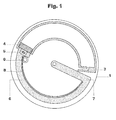
- the injection device shown in Fig. 1 has a casing having a cylindrical side-wall 1 housing a barrel in form of a segment of a toroidal tube 2.
- One end 3 of the barrel is provided with a connecting channel to a cannula (not shown).
- the barrel has a circular cross section.
- a piston 4 is arranged in the interior of the barrel and is provided with a seal fitting tightly at the inner wall of the barrel.
- the piston is connected to a driving rod 6 which is circularly shaped for driving the piston through the entire length of the barrel.
- the driving rod At its end opposite the piston the driving rod has a perpendicularly bent arm 7 extending to a central pivot, thereby reducing the radial component of the force and the resulting friction by moving the piston through the barrel.
- the inner side of the rod has a gear rim 8 which is driven by a gear drive 9.
- the gear drive is driven e.g. by a gear train and an electrical motor (for example a watchwork drive) which can be regulated for controlled delivery by signals from inbuilt and/or remote control elements (not shown in the figure).
- an electrical motor for example a watchwork drive
- other drives as known in prior art, can be employed.
- a difference of only 2% between the radius of the barrel and of the driving rod causes a serious relative shift which can lead to collision between barrel wall and driving rod for torus arcs of e.g. 150° - 160° which can be manufactured with standard technologies and are aimed at in order to sufficiently reduce the footprint of the syringe-type pump.
- the plastics parts usually used to manufacture the housing holding the barrel and the guideways for the driving rod are not absolutely rigid and can slightly deform especially under the applied forces necessary to provide the pressures of several bar to overcome tissue resistance.
- the solution to avoid stick-slip phenomena and/or problems with tightness or even blockage of the piston or clamping between the rigid driving rod and the barrel wall is to use a driving rod of the piston which adapts to the actual curvature of the barrel, being guided and supported by the inner wall of the barrel.
- the rod guided and supported by the inner wall of the barrel of the subject invention can adapt to all deviations from the ideal shape and geometry which are unavoidable using cost-effective manufacturing technologies and materials.
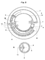
- a preferred embodiment of the subject invention, which can be adapted for both, fluid delivery and fluid withdrawal, is exemplified in Fig 2 .
- Fig 2 shows a combined injection and analysis fluid removal device with two independent circular syringe pumps in top view of a horizontal section.
- the pump for delivery of injection fluid is shown in the more peripheral part of the drawing, whereas in the more central part a pump for removal of analysis fluid is shown.
- parts corresponding to Fig. 1 are given the same reference numbers.
- the embodiment in Fig. 2 does not have a rigid driving rod. Instead, the driving rod 6 of the piston is formed in such a way that its movement is guided and supported by the inner surface of the barrel wall as shown in cross section in Detail A.
- a brace 11 of optimized form and material for even movement with low friction to increase precision and to reduce the necessary forces for piston movement forms the gliding zone between driving rod of the piston and inner surface of the barrel wall.
- This can be achieved by using for the driving rod plastics with suitable gliding properties or by attaching a rim of suitable material, e.g. a steel wire, but other possibilities of friction reduction like e.g. a construction with a number of rolls the axis of which is held by the brace can be implemented in order to avoid gliding resistance and replace it by rolling resistance.
- the radial and axial flexibility of the driving rod exemplified in Detail A can be further increased e.g. by using a segmented structure of the brace holding glidingly a steel wire or the rolls or even a back-bone like structure of the flexible driving rod with segments linked by hinge regions.
- the gear drive 9 is supported by a radially opposing brace 10, preferentially in the form of an antifriction bearing, pressing against the contact rim 11 of the driving rod, but other constructions like e.g. a side-wall attached to the housing are also possible.
- the piston 4 with its sealing e.g. an O- or an X-ring is held in a defined distance from the inner surface of the barrel wall by the brace of the driving rod and transmits only the tangential driving force to the piston.
- the piston is not directly fused rigidly with the end of the driving rod, but movably attached to an end-piece of the driving rod which is held by the brace in a defined distance from the barrel wall. This can be achieved e.g. by a low-friction sliding surface contact between the end-piece of the driving rod and the piston or by balls rolling at the interface.
- Such a self-centering construction might be useful to improve the performance of the pump in case of significant manufacturing process derived variability in the inner shape and diameter of the barrel along its axis.
- a proximally located gear rim 8 to move the piston can also be used e.g. in a construction in which the gear rim is double-tracked and set back respective to the brace 11 and the gear drive 9 has a slit to accommodate the protruding brace.
- Fig 3 is the central part of a tangential cut of the device through the end portion 3 of the barrel.
- a first channel 15 is leading to the upper side of the device and is closed by a septum 14.
- a syringe (not shown) having a needle 13 is pierced through the septum 14.
- the piston is touching the end portion 3 of the barrel (not shown). The injection fluid is introduced through channel 15, thereby pushing the piston towards the opposite end of the barrel.
- a second channel 17 is leading from the interior of barrel 2 to an injection cannula 16 for delivery of injection fluid into the skin.
- the cannula 16 is closed at the other end with a septum-seal 18 which is held in a housing 19.
- the overall construction is such that the dead volume is minimal and no significant volume of air is in the system after filling with injection fluid.
- the insertion means into the skin of the cannula 16 has a flexible base plate 20 which is attached to the skin by an adhesive layer 21.
- this flexible base plate is deformed to a convex shape covering the cannula 16.
- the base plate is preferentially annular or oval and in order to insert a cannula which is remote from the center of the device consists preferentially of two segments with a diagonal slit, forming a gable upon bending. This configuration allows also to use this insertion means for more than one cannula simultaneously which are positioned along the diagonal slit, e.g.
- the septum-seal 18 is pierced by the cannula before it enters the skin.
- the segments are attached to the circumference of the casing 1 by springy hinge regions and are in addition preferentially made of a flexible material.
- Alternative forms like a radial segmentation, preferably into 5 to 8 segments with a spacing between them and a central opening, forming a cone upon central bending are also possible if the cannula is placed close to the center of the device.
- the flexible base plate On its underside, the flexible base plate has an annular or oval adhesive layer for securing the device to the patient's skin with a diagonal slit or a concentric central opening, respectively similar to the base plate.
- This adhesive layer is composed of three parts, a glue for fixing to the flexible base plate, a textile providing the necessary flexibility and a glue for fixing onto the skin. Suitable materials with low allergenicity potential are commercially available.
- the adhesive layer can have a larger circumference than the device but it could have also the same circumference if the attachment to the base plate leaves an outer zone where it is not connected to the housing.
- the pre-stressed base plate Upon release of the pre-stressed base plate actuated e.g. by a sliding bolt mechanism (not shown) it rapidly relaxes to a flat shape towards the bottom of the housing of the device 1, pushes the housing 19 of the septum-seal 18, and the cannula 16 pierces through the septum-seal 18 and through the skin attached by the adhesive layer.
- the drive means for moving the piston or the implantation mechanism of the cannula for delivery of injection fluid into a patient, or for removal of analysis fluid of a patient could be achieved via numerous chemical, mechanical, or electrical means.
- a large variety of diagnostic elements for the online analysis or for sampling of analysis fluid for removed analysis as well as control and measuring means can be accommodated with the device.
- the major advantages of a device with a toroidal syringe-type pump described above are its reduced footprint-size by which it can be comfortably worn and operated by the patient and at the same time the inherent high precision of a syringe type pump.
- the intrinsic problems of such pumps exemplified in prior art of sealing, friction causing stick-slip phenomena, and even blockage caused by lack of exact fit between the actual form of the arcuate barrel and of the plunger unavoidable in manufacturing of the toroidal barrel and the device using standard cost-effective technologies are solved by using as the drive for the piston a driving rod which is guided and supported by the inner wall of the barrel and therefore can adapt to all deviations from the ideal shape and in geometry.
- a further advantage is the absence of the problems with connecting tubings between a syringe pump and the cannula penetrating the skin.
- the device according to the invention has almost no dead volume thus avoiding complicated mechanisms to move air out of the system during filling of the pump with injection fluid.
Landscapes
- Health & Medical Sciences (AREA)
- Life Sciences & Earth Sciences (AREA)
- Engineering & Computer Science (AREA)
- Veterinary Medicine (AREA)
- Animal Behavior & Ethology (AREA)
- Biomedical Technology (AREA)
- Heart & Thoracic Surgery (AREA)
- Public Health (AREA)
- General Health & Medical Sciences (AREA)
- Hematology (AREA)
- Vascular Medicine (AREA)
- Anesthesiology (AREA)
- Physics & Mathematics (AREA)
- Medical Informatics (AREA)
- Surgery (AREA)
- Molecular Biology (AREA)
- Biophysics (AREA)
- Pathology (AREA)
- Diabetes (AREA)
- Dermatology (AREA)
- Computer Networks & Wireless Communication (AREA)
- Physiology (AREA)
- Manufacturing & Machinery (AREA)
- Chemical & Material Sciences (AREA)
- Bioinformatics & Cheminformatics (AREA)
- Medicinal Chemistry (AREA)
- Pharmacology & Pharmacy (AREA)
- Optics & Photonics (AREA)
- Infusion, Injection, And Reservoir Apparatuses (AREA)
Applications Claiming Priority (3)
| Application Number | Priority Date | Filing Date | Title |
|---|---|---|---|
| EP10187141A EP2438938A1 (de) | 2010-10-11 | 2010-10-11 | Spritzenartige Pumpe |
| PCT/EP2011/067535 WO2012049080A2 (en) | 2010-10-11 | 2011-10-07 | Syringe type pump |
| EP11767246.9A EP2627374B1 (de) | 2010-10-11 | 2011-10-07 | Spritzenartige pumpe |
Related Parent Applications (2)
| Application Number | Title | Priority Date | Filing Date |
|---|---|---|---|
| EP11767246.9A Division-Into EP2627374B1 (de) | 2010-10-11 | 2011-10-07 | Spritzenartige pumpe |
| EP11767246.9A Division EP2627374B1 (de) | 2010-10-11 | 2011-10-07 | Spritzenartige pumpe |
Publications (4)
| Publication Number | Publication Date |
|---|---|
| EP2907535A2 true EP2907535A2 (de) | 2015-08-19 |
| EP2907535A3 EP2907535A3 (de) | 2015-11-25 |
| EP2907535B1 EP2907535B1 (de) | 2024-02-07 |
| EP2907535C0 EP2907535C0 (de) | 2024-02-07 |
Family
ID=43533199
Family Applications (3)
| Application Number | Title | Priority Date | Filing Date |
|---|---|---|---|
| EP10187141A Withdrawn EP2438938A1 (de) | 2010-10-11 | 2010-10-11 | Spritzenartige Pumpe |
| EP15154808.8A Active EP2907535B1 (de) | 2010-10-11 | 2011-10-07 | Spritzenartige Pumpe |
| EP11767246.9A Active EP2627374B1 (de) | 2010-10-11 | 2011-10-07 | Spritzenartige pumpe |
Family Applications Before (1)
| Application Number | Title | Priority Date | Filing Date |
|---|---|---|---|
| EP10187141A Withdrawn EP2438938A1 (de) | 2010-10-11 | 2010-10-11 | Spritzenartige Pumpe |
Family Applications After (1)
| Application Number | Title | Priority Date | Filing Date |
|---|---|---|---|
| EP11767246.9A Active EP2627374B1 (de) | 2010-10-11 | 2011-10-07 | Spritzenartige pumpe |
Country Status (8)
| Country | Link |
|---|---|
| US (2) | US10130756B2 (de) |
| EP (3) | EP2438938A1 (de) |
| JP (4) | JP2014502855A (de) |
| CN (2) | CN103313741B (de) |
| CA (2) | CA2813525C (de) |
| DK (1) | DK2627374T3 (de) |
| ES (2) | ES2970794T3 (de) |
| WO (1) | WO2012049080A2 (de) |
Cited By (1)
| Publication number | Priority date | Publication date | Assignee | Title |
|---|---|---|---|---|
| US9925333B2 (en) | 2013-06-18 | 2018-03-27 | Enable Injections, Inc. | Vial transfer and injection apparatus and method |
Families Citing this family (22)
| Publication number | Priority date | Publication date | Assignee | Title |
|---|---|---|---|---|
| EP2650032A1 (de) * | 2012-04-11 | 2013-10-16 | PharmaSens AG | Subkutaner Nadeleinführungsmechanismus |
| EP2679154A1 (de) | 2012-06-25 | 2014-01-01 | PharmaSens AG | Subepidermale elektrische Warnvorrichtung |
| EP2879741B1 (de) * | 2012-07-31 | 2021-04-28 | Nipro Healthcare Systems, LLC | Vorrichtung und verfahren zur abgabe einer flüssigkeit aus einer infusionspumpe |
| US20150217058A1 (en) * | 2012-09-24 | 2015-08-06 | Enable Injections, Llc | Medical vial and injector assemblies and methods of use |
| EP2716315A1 (de) * | 2012-10-08 | 2014-04-09 | IN. Medica, d.o.o. | Präzisionsflüssigkeitsspendervorrichtung |
| IN2015DN02977A (de) | 2012-10-16 | 2015-09-18 | Swissinnov Product S Rl | |
| EP2842586A1 (de) | 2013-08-27 | 2015-03-04 | PharmaSens AG | Vorrichtung mit einem Lavet-Motor |
| RU2016119380A (ru) * | 2013-10-31 | 2017-12-05 | Свиссиннов Продакт Сарл | Портативный насос и способ его изготовления |
| KR101615745B1 (ko) | 2014-08-20 | 2016-04-26 | 서울대학교 산학협력단 | 적층이 가능한 휘어진 주사기 형태의 약물저장부를 구비하는 약물주입펌프 |
| US20160051755A1 (en) * | 2014-08-25 | 2016-02-25 | Medtronic Minimed, Inc. | Low cost fluid delivery device |
| US20210338928A1 (en) * | 2017-01-23 | 2021-11-04 | Enable Injections, Inc. | Medical fluid injection device with fill indicator |
| US20180207369A1 (en) * | 2017-01-23 | 2018-07-26 | Enable Injections, Inc. | Medical fluid injection device with fill indicator |
| CN108844571B (zh) * | 2018-07-16 | 2024-08-30 | 河北农业大学 | 一种禽舍有害气体传感器在线校准标定装置及其方法 |
| US12539361B2 (en) | 2019-02-22 | 2026-02-03 | Deka Products Limited Partnership | Infusion set and inserter assembly apparatuses, systems, and methods |
| EP4643904A3 (de) | 2019-02-22 | 2026-04-29 | DEKA Products Limited Partnership | Infusionsset und einsetzanordnungssysteme und -verfahren |
| US11324881B2 (en) * | 2019-11-21 | 2022-05-10 | Medtronic Minimed, Inc. | Systems for wearable infusion port and associated pump |
| CN112755322A (zh) * | 2021-03-02 | 2021-05-07 | 河南理工大学 | 基于光栅传感器的免挂式刻度调速压力输液手环 |
| CN113499508B (zh) * | 2021-07-14 | 2022-08-26 | 巨翊科技(上海)有限公司 | 一种自动卡和输液管的输液泵 |
| CN118076397A (zh) | 2021-10-07 | 2024-05-24 | 贝克顿·迪金森公司 | 用于医用注射器的弯曲式贮存器 |
| CN116236192B (zh) * | 2021-12-07 | 2025-11-11 | 上海微创生命科技有限公司 | 一种连续血糖监测装置及连续血糖监测系统 |
| US12114843B2 (en) | 2022-03-31 | 2024-10-15 | Ethicon, Inc. | Sealant applicators having mixing and spraying assemblies with malleable sections and spray tips having reduced dimensions |
| US12220118B2 (en) | 2022-03-31 | 2025-02-11 | Ethicon, Inc. | Systems, devices and methods for reconstituting therapeutic powders, mixing precursor solutions, and expressing sealants for controlling bleeding and sealing fluid and air leaks |
Citations (4)
| Publication number | Priority date | Publication date | Assignee | Title |
|---|---|---|---|---|
| US4525164A (en) | 1981-04-24 | 1985-06-25 | Biotek, Inc. | Wearable medication infusion system with arcuated reservoir |
| EP0825882A1 (de) | 1995-05-22 | 1998-03-04 | F. Hoffmann-La Roche Ag | An der haut haftende medizinische vorrichtung |
| WO2008024812A2 (en) | 2006-08-23 | 2008-02-28 | Medtronic Minimed, Inc. | Infusion medium delivery device and method with compressible or curved reservoir or conduit |
| WO2008139458A2 (en) | 2007-05-11 | 2008-11-20 | Medingo Ltd. | A positive displacement pump |
Family Cites Families (29)
| Publication number | Priority date | Publication date | Assignee | Title |
|---|---|---|---|---|
| AT280218B (de) * | 1965-04-07 | 1970-04-10 | Ceskoslovenska Akademie Ved | Verfahren und Vorrichtung zur Verminderung einer nachträglichen Vermischung bereits getrennter Komponenten |
| US4393870A (en) * | 1974-11-19 | 1983-07-19 | Wolfgang Wagner | Suction injector |
| AT384737B (de) * | 1986-04-04 | 1987-12-28 | Thoma Dipl Ing Dr Techn Herwig | Vorrichtung zur stroemungskonstanten abgabe fluessiger arzneimittel |
| CA1283827C (en) * | 1986-12-18 | 1991-05-07 | Giorgio Cirelli | Appliance for injection of liquid formulations |
| CA2159052C (en) * | 1994-10-28 | 2007-03-06 | Rainer Alex | Injection device |
| US6149604A (en) * | 1995-09-07 | 2000-11-21 | Kosasky; Harold J. | Instrument for measuring saliva viscoelasticity to determine female fertile period |
| IL127557A0 (en) * | 1996-07-05 | 1999-10-28 | Novo Nordisk As | Flexible piston rod |
| US6607509B2 (en) * | 1997-12-31 | 2003-08-19 | Medtronic Minimed, Inc. | Insertion device for an insertion set and method of using the same |
| US6186982B1 (en) * | 1998-05-05 | 2001-02-13 | Elan Corporation, Plc | Subcutaneous drug delivery device with improved filling system |
| US6530900B1 (en) * | 1997-05-06 | 2003-03-11 | Elan Pharma International Limited | Drug delivery device |
| DK1189660T3 (da) * | 1999-06-08 | 2006-08-21 | Altea Therapeutics Corp | Apparat til mikroperforering af biologiske membraner ved hjælp af tyndfilms-vævsgrænseflade-anordninger samt fremgangsmåde til fremstilling deraf |
| US6585699B2 (en) * | 2000-04-13 | 2003-07-01 | Nna/S | Drug delivery device provided with a one-way mechanism |
| US6589229B1 (en) * | 2000-07-31 | 2003-07-08 | Becton, Dickinson And Company | Wearable, self-contained drug infusion device |
| ATE293466T1 (de) * | 2000-08-18 | 2005-05-15 | Becton Dickinson Co | Vorrichtung zum verabreichen einer flüssigkeit mit einem konstanten volumenstrom und einem knopf für eine einstellbare bolusabgabe |
| US6537251B2 (en) * | 2000-10-05 | 2003-03-25 | Novo Nordisk A/S | Medication delivery device with bended piston rod |
| US8784335B2 (en) * | 2002-04-19 | 2014-07-22 | Sanofi-Aventis Deutschland Gmbh | Body fluid sampling device with a capacitive sensor |
| US7014625B2 (en) * | 2002-10-07 | 2006-03-21 | Novo Nordick A/S | Needle insertion device |
| EP1554001B1 (de) * | 2002-10-07 | 2009-05-13 | Novo Nordisk A/S | Nadel-insertionsvorrichtung |
| JP4522364B2 (ja) * | 2002-11-01 | 2010-08-11 | ペリカン テクノロジーズ インコーポレイテッド | 体液のサンプル採取装置 |
| US8532730B2 (en) * | 2006-10-04 | 2013-09-10 | Dexcom, Inc. | Analyte sensor |
| GB0420062D0 (en) * | 2004-09-09 | 2004-10-13 | Akubio Ltd | Assay methods,materials and preparations |
| US9259175B2 (en) * | 2006-10-23 | 2016-02-16 | Abbott Diabetes Care, Inc. | Flexible patch for fluid delivery and monitoring body analytes |
| US9233203B2 (en) * | 2005-05-06 | 2016-01-12 | Medtronic Minimed, Inc. | Medical needles for damping motion |
| DE202006004748U1 (de) * | 2005-12-13 | 2007-04-26 | Trw Automotive Gmbh | Gurtstraffer für ein Sicherheitsgurtsystem |
| US20070299399A1 (en) * | 2006-03-16 | 2007-12-27 | Seattle Medical Technologies | Infusion device with dosage dial control |
| WO2007141210A1 (en) * | 2006-06-06 | 2007-12-13 | Novo Nordisk A/S | Assembly comprising skin-mountable device and packaging therefore |
| WO2008080990A1 (de) * | 2006-12-29 | 2008-07-10 | Disetronic Licensing Ag | Extrakorporal tragbare infusionsvorrichtung |
| WO2009016636A2 (en) * | 2007-08-01 | 2009-02-05 | Medingo Ltd. | Portable infusion device provided with means for monitoring and controlling fluid delivery |
| CA2993719C (en) * | 2009-01-12 | 2022-04-19 | Becton, Dickinson And Company | Infusion set and/or patch pump having at least one of an in-dwelling rigid catheter with flexible features and/or a flexible catheter attachment |
-
2010
- 2010-10-11 EP EP10187141A patent/EP2438938A1/de not_active Withdrawn
-
2011
- 2011-10-07 ES ES15154808T patent/ES2970794T3/es active Active
- 2011-10-07 US US13/878,569 patent/US10130756B2/en active Active
- 2011-10-07 CA CA2813525A patent/CA2813525C/en active Active
- 2011-10-07 EP EP15154808.8A patent/EP2907535B1/de active Active
- 2011-10-07 EP EP11767246.9A patent/EP2627374B1/de active Active
- 2011-10-07 ES ES11767246.9T patent/ES2671244T3/es active Active
- 2011-10-07 CN CN201180049140.2A patent/CN103313741B/zh active Active
- 2011-10-07 CA CA2895617A patent/CA2895617C/en active Active
- 2011-10-07 WO PCT/EP2011/067535 patent/WO2012049080A2/en not_active Ceased
- 2011-10-07 CN CN201510344617.XA patent/CN105126194B/zh active Active
- 2011-10-07 DK DK11767246.9T patent/DK2627374T3/en active
- 2011-10-07 JP JP2013533159A patent/JP2014502855A/ja active Pending
-
2015
- 2015-06-15 US US14/738,995 patent/US10117989B2/en active Active
- 2015-08-11 JP JP2015159098A patent/JP6490534B2/ja active Active
-
2016
- 2016-06-16 JP JP2016120214A patent/JP6434454B2/ja active Active
-
2017
- 2017-05-08 JP JP2017092697A patent/JP6423916B2/ja active Active
Patent Citations (4)
| Publication number | Priority date | Publication date | Assignee | Title |
|---|---|---|---|---|
| US4525164A (en) | 1981-04-24 | 1985-06-25 | Biotek, Inc. | Wearable medication infusion system with arcuated reservoir |
| EP0825882A1 (de) | 1995-05-22 | 1998-03-04 | F. Hoffmann-La Roche Ag | An der haut haftende medizinische vorrichtung |
| WO2008024812A2 (en) | 2006-08-23 | 2008-02-28 | Medtronic Minimed, Inc. | Infusion medium delivery device and method with compressible or curved reservoir or conduit |
| WO2008139458A2 (en) | 2007-05-11 | 2008-11-20 | Medingo Ltd. | A positive displacement pump |
Cited By (2)
| Publication number | Priority date | Publication date | Assignee | Title |
|---|---|---|---|---|
| US9925333B2 (en) | 2013-06-18 | 2018-03-27 | Enable Injections, Inc. | Vial transfer and injection apparatus and method |
| US11040138B2 (en) | 2013-06-18 | 2021-06-22 | Enable Injections, Inc. | Vial transfer and injection apparatus and method |
Also Published As
| Publication number | Publication date |
|---|---|
| CA2895617A1 (en) | 2012-04-19 |
| DK2627374T3 (en) | 2018-06-14 |
| US20130324884A1 (en) | 2013-12-05 |
| HK1184403A1 (en) | 2014-01-24 |
| CN103313741B (zh) | 2015-07-15 |
| EP2627374B1 (de) | 2018-02-28 |
| EP2907535B1 (de) | 2024-02-07 |
| US10117989B2 (en) | 2018-11-06 |
| EP2627374A2 (de) | 2013-08-21 |
| CA2895617C (en) | 2020-12-29 |
| JP6434454B2 (ja) | 2018-12-05 |
| US20150273139A1 (en) | 2015-10-01 |
| JP2014502855A (ja) | 2014-02-06 |
| ES2970794T3 (es) | 2024-05-30 |
| EP2907535A3 (de) | 2015-11-25 |
| JP2016190058A (ja) | 2016-11-10 |
| CA2813525A1 (en) | 2012-04-19 |
| EP2438938A1 (de) | 2012-04-11 |
| JP6423916B2 (ja) | 2018-11-14 |
| CN105126194B (zh) | 2019-05-17 |
| ES2671244T3 (es) | 2018-06-05 |
| JP2017148596A (ja) | 2017-08-31 |
| US10130756B2 (en) | 2018-11-20 |
| WO2012049080A3 (en) | 2012-06-28 |
| JP2015231560A (ja) | 2015-12-24 |
| HK1213207A1 (zh) | 2016-06-30 |
| EP2907535C0 (de) | 2024-02-07 |
| WO2012049080A2 (en) | 2012-04-19 |
| CN103313741A (zh) | 2013-09-18 |
| CN105126194A (zh) | 2015-12-09 |
| JP6490534B2 (ja) | 2019-03-27 |
| CA2813525C (en) | 2019-01-15 |
Similar Documents
| Publication | Publication Date | Title |
|---|---|---|
| EP2627374B1 (de) | Spritzenartige pumpe | |
| KR102143025B1 (ko) | 피하주사 바늘 삽입 메커니즘 | |
| EP1624914B1 (de) | Interne nadeleinführvorrichtung | |
| EP2694135B1 (de) | An der haut befestigte vorrichtung für intravenösen zugang | |
| HK1213207B (zh) | 用於将流体皮下注射到病人体内的设备 | |
| HK1184403B (en) | Syringe type pump | |
| HK1201219B (en) | Subcutaneous needle insertion mechanism | |
| HK1191582A (en) | Dermally affixed device for intravenous access |
Legal Events
| Date | Code | Title | Description |
|---|---|---|---|
| PUAI | Public reference made under article 153(3) epc to a published international application that has entered the european phase |
Free format text: ORIGINAL CODE: 0009012 |
|
| AC | Divisional application: reference to earlier application |
Ref document number: 2627374 Country of ref document: EP Kind code of ref document: P |
|
| AK | Designated contracting states |
Kind code of ref document: A2 Designated state(s): AL AT BE BG CH CY CZ DE DK EE ES FI FR GB GR HR HU IE IS IT LI LT LU LV MC MK MT NL NO PL PT RO RS SE SI SK SM TR |
|
| PUAL | Search report despatched |
Free format text: ORIGINAL CODE: 0009013 |
|
| AK | Designated contracting states |
Kind code of ref document: A3 Designated state(s): AL AT BE BG CH CY CZ DE DK EE ES FI FR GB GR HR HU IE IS IT LI LT LU LV MC MK MT NL NO PL PT RO RS SE SI SK SM TR |
|
| RIC1 | Information provided on ipc code assigned before grant |
Ipc: A61M 5/158 20060101AFI20151021BHEP Ipc: A61M 5/32 20060101ALI20151021BHEP Ipc: A61M 5/142 20060101ALI20151021BHEP Ipc: A61B 5/15 20060101ALI20151021BHEP Ipc: A61M 5/31 20060101ALI20151021BHEP Ipc: A61M 5/172 20060101ALI20151021BHEP Ipc: A61M 5/315 20060101ALI20151021BHEP Ipc: A61M 5/145 20060101ALI20151021BHEP |
|
| 17P | Request for examination filed |
Effective date: 20160525 |
|
| RBV | Designated contracting states (corrected) |
Designated state(s): AL AT BE BG CH CY CZ DE DK EE ES FI FR GB GR HR HU IE IS IT LI LT LU LV MC MK MT NL NO PL PT RO RS SE SI SK SM TR |
|
| STAA | Information on the status of an ep patent application or granted ep patent |
Free format text: STATUS: EXAMINATION IS IN PROGRESS |
|
| 17Q | First examination report despatched |
Effective date: 20190409 |
|
| GRAP | Despatch of communication of intention to grant a patent |
Free format text: ORIGINAL CODE: EPIDOSNIGR1 |
|
| STAA | Information on the status of an ep patent application or granted ep patent |
Free format text: STATUS: GRANT OF PATENT IS INTENDED |
|
| INTG | Intention to grant announced |
Effective date: 20231121 |
|
| GRAS | Grant fee paid |
Free format text: ORIGINAL CODE: EPIDOSNIGR3 |
|
| GRAA | (expected) grant |
Free format text: ORIGINAL CODE: 0009210 |
|
| STAA | Information on the status of an ep patent application or granted ep patent |
Free format text: STATUS: THE PATENT HAS BEEN GRANTED |
|
| AC | Divisional application: reference to earlier application |
Ref document number: 2627374 Country of ref document: EP Kind code of ref document: P |
|
| AK | Designated contracting states |
Kind code of ref document: B1 Designated state(s): AL AT BE BG CH CY CZ DE DK EE ES FI FR GB GR HR HU IE IS IT LI LT LU LV MC MK MT NL NO PL PT RO RS SE SI SK SM TR |
|
| REG | Reference to a national code |
Ref country code: GB Ref legal event code: FG4D |
|
| REG | Reference to a national code |
Ref country code: CH Ref legal event code: EP |
|
| REG | Reference to a national code |
Ref country code: DE Ref legal event code: R096 Ref document number: 602011074565 Country of ref document: DE |
|
| REG | Reference to a national code |
Ref country code: IE Ref legal event code: FG4D |
|
| U01 | Request for unitary effect filed |
Effective date: 20240207 |
|
| U07 | Unitary effect registered |
Designated state(s): AT BE BG DE DK EE FI FR IT LT LU LV MT NL PT SE SI Effective date: 20240213 |
|
| REG | Reference to a national code |
Ref country code: ES Ref legal event code: FG2A Ref document number: 2970794 Country of ref document: ES Kind code of ref document: T3 Effective date: 20240530 |
|
| PG25 | Lapsed in a contracting state [announced via postgrant information from national office to epo] |
Ref country code: IS Free format text: LAPSE BECAUSE OF FAILURE TO SUBMIT A TRANSLATION OF THE DESCRIPTION OR TO PAY THE FEE WITHIN THE PRESCRIBED TIME-LIMIT Effective date: 20240607 |
|
| PG25 | Lapsed in a contracting state [announced via postgrant information from national office to epo] |
Ref country code: GR Free format text: LAPSE BECAUSE OF FAILURE TO SUBMIT A TRANSLATION OF THE DESCRIPTION OR TO PAY THE FEE WITHIN THE PRESCRIBED TIME-LIMIT Effective date: 20240508 |
|
| PG25 | Lapsed in a contracting state [announced via postgrant information from national office to epo] |
Ref country code: HR Free format text: LAPSE BECAUSE OF FAILURE TO SUBMIT A TRANSLATION OF THE DESCRIPTION OR TO PAY THE FEE WITHIN THE PRESCRIBED TIME-LIMIT Effective date: 20240207 Ref country code: RS Free format text: LAPSE BECAUSE OF FAILURE TO SUBMIT A TRANSLATION OF THE DESCRIPTION OR TO PAY THE FEE WITHIN THE PRESCRIBED TIME-LIMIT Effective date: 20240507 |
|
| PG25 | Lapsed in a contracting state [announced via postgrant information from national office to epo] |
Ref country code: RS Free format text: LAPSE BECAUSE OF FAILURE TO SUBMIT A TRANSLATION OF THE DESCRIPTION OR TO PAY THE FEE WITHIN THE PRESCRIBED TIME-LIMIT Effective date: 20240507 Ref country code: NO Free format text: LAPSE BECAUSE OF FAILURE TO SUBMIT A TRANSLATION OF THE DESCRIPTION OR TO PAY THE FEE WITHIN THE PRESCRIBED TIME-LIMIT Effective date: 20240507 Ref country code: IS Free format text: LAPSE BECAUSE OF FAILURE TO SUBMIT A TRANSLATION OF THE DESCRIPTION OR TO PAY THE FEE WITHIN THE PRESCRIBED TIME-LIMIT Effective date: 20240607 Ref country code: HR Free format text: LAPSE BECAUSE OF FAILURE TO SUBMIT A TRANSLATION OF THE DESCRIPTION OR TO PAY THE FEE WITHIN THE PRESCRIBED TIME-LIMIT Effective date: 20240207 Ref country code: GR Free format text: LAPSE BECAUSE OF FAILURE TO SUBMIT A TRANSLATION OF THE DESCRIPTION OR TO PAY THE FEE WITHIN THE PRESCRIBED TIME-LIMIT Effective date: 20240508 |
|
| PG25 | Lapsed in a contracting state [announced via postgrant information from national office to epo] |
Ref country code: PL Free format text: LAPSE BECAUSE OF FAILURE TO SUBMIT A TRANSLATION OF THE DESCRIPTION OR TO PAY THE FEE WITHIN THE PRESCRIBED TIME-LIMIT Effective date: 20240207 |
|
| PG25 | Lapsed in a contracting state [announced via postgrant information from national office to epo] |
Ref country code: PL Free format text: LAPSE BECAUSE OF FAILURE TO SUBMIT A TRANSLATION OF THE DESCRIPTION OR TO PAY THE FEE WITHIN THE PRESCRIBED TIME-LIMIT Effective date: 20240207 |
|
| PG25 | Lapsed in a contracting state [announced via postgrant information from national office to epo] |
Ref country code: SM Free format text: LAPSE BECAUSE OF FAILURE TO SUBMIT A TRANSLATION OF THE DESCRIPTION OR TO PAY THE FEE WITHIN THE PRESCRIBED TIME-LIMIT Effective date: 20240207 |
|
| PG25 | Lapsed in a contracting state [announced via postgrant information from national office to epo] |
Ref country code: CZ Free format text: LAPSE BECAUSE OF FAILURE TO SUBMIT A TRANSLATION OF THE DESCRIPTION OR TO PAY THE FEE WITHIN THE PRESCRIBED TIME-LIMIT Effective date: 20240207 |
|
| PG25 | Lapsed in a contracting state [announced via postgrant information from national office to epo] |
Ref country code: SK Free format text: LAPSE BECAUSE OF FAILURE TO SUBMIT A TRANSLATION OF THE DESCRIPTION OR TO PAY THE FEE WITHIN THE PRESCRIBED TIME-LIMIT Effective date: 20240207 |
|
| PG25 | Lapsed in a contracting state [announced via postgrant information from national office to epo] |
Ref country code: SM Free format text: LAPSE BECAUSE OF FAILURE TO SUBMIT A TRANSLATION OF THE DESCRIPTION OR TO PAY THE FEE WITHIN THE PRESCRIBED TIME-LIMIT Effective date: 20240207 Ref country code: SK Free format text: LAPSE BECAUSE OF FAILURE TO SUBMIT A TRANSLATION OF THE DESCRIPTION OR TO PAY THE FEE WITHIN THE PRESCRIBED TIME-LIMIT Effective date: 20240207 Ref country code: RO Free format text: LAPSE BECAUSE OF FAILURE TO SUBMIT A TRANSLATION OF THE DESCRIPTION OR TO PAY THE FEE WITHIN THE PRESCRIBED TIME-LIMIT Effective date: 20240207 Ref country code: CZ Free format text: LAPSE BECAUSE OF FAILURE TO SUBMIT A TRANSLATION OF THE DESCRIPTION OR TO PAY THE FEE WITHIN THE PRESCRIBED TIME-LIMIT Effective date: 20240207 |
|
| REG | Reference to a national code |
Ref country code: DE Ref legal event code: R097 Ref document number: 602011074565 Country of ref document: DE |
|
| U20 | Renewal fee for the european patent with unitary effect paid |
Year of fee payment: 14 Effective date: 20241025 |
|
| PLBE | No opposition filed within time limit |
Free format text: ORIGINAL CODE: 0009261 |
|
| STAA | Information on the status of an ep patent application or granted ep patent |
Free format text: STATUS: NO OPPOSITION FILED WITHIN TIME LIMIT |
|
| 26N | No opposition filed |
Effective date: 20241108 |
|
| PGFP | Annual fee paid to national office [announced via postgrant information from national office to epo] |
Ref country code: ES Payment date: 20241127 Year of fee payment: 14 |
|
| PG25 | Lapsed in a contracting state [announced via postgrant information from national office to epo] |
Ref country code: MC Free format text: LAPSE BECAUSE OF FAILURE TO SUBMIT A TRANSLATION OF THE DESCRIPTION OR TO PAY THE FEE WITHIN THE PRESCRIBED TIME-LIMIT Effective date: 20240207 |
|
| U1H | Name or address of the proprietor changed after the registration of the unitary effect |
Owner name: PHARMASENS AG; CH |
|
| U1N | Appointed representative for the unitary patent procedure changed after the registration of the unitary effect |
Representative=s name: MAYER, ALINE SOPHIE; CH |
|
| PG25 | Lapsed in a contracting state [announced via postgrant information from national office to epo] |
Ref country code: IE Free format text: LAPSE BECAUSE OF NON-PAYMENT OF DUE FEES Effective date: 20241007 |
|
| REG | Reference to a national code |
Ref country code: CH Ref legal event code: U11 Free format text: ST27 STATUS EVENT CODE: U-0-0-U10-U11 (AS PROVIDED BY THE NATIONAL OFFICE) Effective date: 20251101 |
|
| U20 | Renewal fee for the european patent with unitary effect paid |
Year of fee payment: 15 Effective date: 20251013 |
|
| PGFP | Annual fee paid to national office [announced via postgrant information from national office to epo] |
Ref country code: GB Payment date: 20251022 Year of fee payment: 15 |
|
| PGFP | Annual fee paid to national office [announced via postgrant information from national office to epo] |
Ref country code: CH Payment date: 20251101 Year of fee payment: 15 |
|
| PG25 | Lapsed in a contracting state [announced via postgrant information from national office to epo] |
Ref country code: CY Free format text: LAPSE BECAUSE OF FAILURE TO SUBMIT A TRANSLATION OF THE DESCRIPTION OR TO PAY THE FEE WITHIN THE PRESCRIBED TIME-LIMIT; INVALID AB INITIO Effective date: 20111007 |
|
| PG25 | Lapsed in a contracting state [announced via postgrant information from national office to epo] |
Ref country code: HU Free format text: LAPSE BECAUSE OF FAILURE TO SUBMIT A TRANSLATION OF THE DESCRIPTION OR TO PAY THE FEE WITHIN THE PRESCRIBED TIME-LIMIT; INVALID AB INITIO Effective date: 20111007 |