EP2907649B1 - Herstellungsverfahren mindestens eines flexiblen behälters aus plastikmaterial - Google Patents
Herstellungsverfahren mindestens eines flexiblen behälters aus plastikmaterial Download PDFInfo
- Publication number
- EP2907649B1 EP2907649B1 EP15155232.0A EP15155232A EP2907649B1 EP 2907649 B1 EP2907649 B1 EP 2907649B1 EP 15155232 A EP15155232 A EP 15155232A EP 2907649 B1 EP2907649 B1 EP 2907649B1
- Authority
- EP
- European Patent Office
- Prior art keywords
- container
- sheets
- peripheral edge
- une
- stack
- Prior art date
- Legal status (The legal status is an assumption and is not a legal conclusion. Google has not performed a legal analysis and makes no representation as to the accuracy of the status listed.)
- Active
Links
Images


Classifications
-
- A—HUMAN NECESSITIES
- A01—AGRICULTURE; FORESTRY; ANIMAL HUSBANDRY; HUNTING; TRAPPING; FISHING
- A01N—PRESERVATION OF BODIES OF HUMANS OR ANIMALS OR PLANTS OR PARTS THEREOF; BIOCIDES, e.g. AS DISINFECTANTS, AS PESTICIDES OR AS HERBICIDES; PEST REPELLANTS OR ATTRACTANTS; PLANT GROWTH REGULATORS
- A01N1/00—Preservation of bodies of humans or animals, or parts thereof
- A01N1/10—Preservation of living parts
- A01N1/14—Mechanical aspects of preservation; Apparatus or containers therefor
- A01N1/146—Non-refrigerated containers specially adapted for transporting or storing living parts whilst preserving
- A01N1/147—Carriers for immersion in cryogenic fluid for slow freezing or vitrification
-
- B—PERFORMING OPERATIONS; TRANSPORTING
- B29—WORKING OF PLASTICS; WORKING OF SUBSTANCES IN A PLASTIC STATE IN GENERAL
- B29C—SHAPING OR JOINING OF PLASTICS; SHAPING OF MATERIAL IN A PLASTIC STATE, NOT OTHERWISE PROVIDED FOR; AFTER-TREATMENT OF THE SHAPED PRODUCTS, e.g. REPAIRING
- B29C51/00—Shaping by thermoforming, i.e. shaping sheets or sheet like preforms after heating, e.g. shaping sheets in matched moulds or by deep-drawing; Apparatus therefor
- B29C51/08—Deep drawing or matched-mould forming, i.e. using mechanical means only
- B29C51/082—Deep drawing or matched-mould forming, i.e. using mechanical means only by shaping between complementary mould parts
-
- B—PERFORMING OPERATIONS; TRANSPORTING
- B29—WORKING OF PLASTICS; WORKING OF SUBSTANCES IN A PLASTIC STATE IN GENERAL
- B29C—SHAPING OR JOINING OF PLASTICS; SHAPING OF MATERIAL IN A PLASTIC STATE, NOT OTHERWISE PROVIDED FOR; AFTER-TREATMENT OF THE SHAPED PRODUCTS, e.g. REPAIRING
- B29C51/00—Shaping by thermoforming, i.e. shaping sheets or sheet like preforms after heating, e.g. shaping sheets in matched moulds or by deep-drawing; Apparatus therefor
- B29C51/10—Forming by pressure difference, e.g. vacuum
- B29C51/105—Twin sheet thermoforming, i.e. deforming two parallel opposing sheets or foils at the same time by using one common mould cavity and without welding them together during thermoforming
-
- B—PERFORMING OPERATIONS; TRANSPORTING
- B29—WORKING OF PLASTICS; WORKING OF SUBSTANCES IN A PLASTIC STATE IN GENERAL
- B29C—SHAPING OR JOINING OF PLASTICS; SHAPING OF MATERIAL IN A PLASTIC STATE, NOT OTHERWISE PROVIDED FOR; AFTER-TREATMENT OF THE SHAPED PRODUCTS, e.g. REPAIRING
- B29C51/00—Shaping by thermoforming, i.e. shaping sheets or sheet like preforms after heating, e.g. shaping sheets in matched moulds or by deep-drawing; Apparatus therefor
- B29C51/12—Shaping by thermoforming, i.e. shaping sheets or sheet like preforms after heating, e.g. shaping sheets in matched moulds or by deep-drawing; Apparatus therefor of articles having inserts or reinforcements
-
- B—PERFORMING OPERATIONS; TRANSPORTING
- B29—WORKING OF PLASTICS; WORKING OF SUBSTANCES IN A PLASTIC STATE IN GENERAL
- B29C—SHAPING OR JOINING OF PLASTICS; SHAPING OF MATERIAL IN A PLASTIC STATE, NOT OTHERWISE PROVIDED FOR; AFTER-TREATMENT OF THE SHAPED PRODUCTS, e.g. REPAIRING
- B29C65/00—Joining or sealing of preformed parts, e.g. welding of plastics materials; Apparatus therefor
- B29C65/02—Joining or sealing of preformed parts, e.g. welding of plastics materials; Apparatus therefor by heating, with or without pressure
- B29C65/18—Joining or sealing of preformed parts, e.g. welding of plastics materials; Apparatus therefor by heating, with or without pressure using heated tools
-
- B—PERFORMING OPERATIONS; TRANSPORTING
- B29—WORKING OF PLASTICS; WORKING OF SUBSTANCES IN A PLASTIC STATE IN GENERAL
- B29C—SHAPING OR JOINING OF PLASTICS; SHAPING OF MATERIAL IN A PLASTIC STATE, NOT OTHERWISE PROVIDED FOR; AFTER-TREATMENT OF THE SHAPED PRODUCTS, e.g. REPAIRING
- B29C65/00—Joining or sealing of preformed parts, e.g. welding of plastics materials; Apparatus therefor
- B29C65/78—Means for handling the parts to be joined, e.g. for making containers or hollow articles, e.g. means for handling sheets, plates, web-like materials, tubular articles, hollow articles or elements to be joined therewith; Means for discharging the joined articles from the joining apparatus
- B29C65/7841—Holding or clamping means for handling purposes
- B29C65/7847—Holding or clamping means for handling purposes using vacuum to hold at least one of the parts to be joined
-
- B—PERFORMING OPERATIONS; TRANSPORTING
- B29—WORKING OF PLASTICS; WORKING OF SUBSTANCES IN A PLASTIC STATE IN GENERAL
- B29C—SHAPING OR JOINING OF PLASTICS; SHAPING OF MATERIAL IN A PLASTIC STATE, NOT OTHERWISE PROVIDED FOR; AFTER-TREATMENT OF THE SHAPED PRODUCTS, e.g. REPAIRING
- B29C66/00—General aspects of processes or apparatus for joining preformed parts
- B29C66/01—General aspects dealing with the joint area or with the area to be joined
- B29C66/05—Particular design of joint configurations
- B29C66/10—Particular design of joint configurations particular design of the joint cross-sections
- B29C66/13—Single flanged joints; Fin-type joints; Single hem joints; Edge joints; Interpenetrating fingered joints; Other specific particular designs of joint cross-sections not provided for in groups B29C66/11 - B29C66/12
- B29C66/131—Single flanged joints, i.e. one of the parts to be joined being rigid and flanged in the joint area
- B29C66/1312—Single flange to flange joints, the parts to be joined being rigid
-
- B—PERFORMING OPERATIONS; TRANSPORTING
- B29—WORKING OF PLASTICS; WORKING OF SUBSTANCES IN A PLASTIC STATE IN GENERAL
- B29C—SHAPING OR JOINING OF PLASTICS; SHAPING OF MATERIAL IN A PLASTIC STATE, NOT OTHERWISE PROVIDED FOR; AFTER-TREATMENT OF THE SHAPED PRODUCTS, e.g. REPAIRING
- B29C66/00—General aspects of processes or apparatus for joining preformed parts
- B29C66/50—General aspects of joining tubular articles; General aspects of joining long products, i.e. bars or profiled elements; General aspects of joining single elements to tubular articles, hollow articles or bars; General aspects of joining several hollow-preforms to form hollow or tubular articles
- B29C66/51—Joining tubular articles, profiled elements or bars; Joining single elements to tubular articles, hollow articles or bars; Joining several hollow-preforms to form hollow or tubular articles
- B29C66/53—Joining single elements to tubular articles, hollow articles or bars
- B29C66/532—Joining single elements to the wall of tubular articles, hollow articles or bars
- B29C66/5326—Joining single elements to the wall of tubular articles, hollow articles or bars said single elements being substantially flat
- B29C66/53261—Enclosing tubular articles between substantially flat elements
- B29C66/53262—Enclosing spouts between the walls of bags, e.g. of medical bags
-
- B—PERFORMING OPERATIONS; TRANSPORTING
- B29—WORKING OF PLASTICS; WORKING OF SUBSTANCES IN A PLASTIC STATE IN GENERAL
- B29C—SHAPING OR JOINING OF PLASTICS; SHAPING OF MATERIAL IN A PLASTIC STATE, NOT OTHERWISE PROVIDED FOR; AFTER-TREATMENT OF THE SHAPED PRODUCTS, e.g. REPAIRING
- B29C66/00—General aspects of processes or apparatus for joining preformed parts
- B29C66/50—General aspects of joining tubular articles; General aspects of joining long products, i.e. bars or profiled elements; General aspects of joining single elements to tubular articles, hollow articles or bars; General aspects of joining several hollow-preforms to form hollow or tubular articles
- B29C66/51—Joining tubular articles, profiled elements or bars; Joining single elements to tubular articles, hollow articles or bars; Joining several hollow-preforms to form hollow or tubular articles
- B29C66/54—Joining several hollow-preforms, e.g. half-shells, to form hollow articles, e.g. for making balls, containers; Joining several hollow-preforms, e.g. half-cylinders, to form tubular articles
-
- B—PERFORMING OPERATIONS; TRANSPORTING
- B29—WORKING OF PLASTICS; WORKING OF SUBSTANCES IN A PLASTIC STATE IN GENERAL
- B29C—SHAPING OR JOINING OF PLASTICS; SHAPING OF MATERIAL IN A PLASTIC STATE, NOT OTHERWISE PROVIDED FOR; AFTER-TREATMENT OF THE SHAPED PRODUCTS, e.g. REPAIRING
- B29C66/00—General aspects of processes or apparatus for joining preformed parts
- B29C66/80—General aspects of machine operations or constructions and parts thereof
- B29C66/83—General aspects of machine operations or constructions and parts thereof characterised by the movement of the joining or pressing tools
- B29C66/832—Reciprocating joining or pressing tools
- B29C66/8322—Joining or pressing tools reciprocating along one axis
-
- B—PERFORMING OPERATIONS; TRANSPORTING
- B29—WORKING OF PLASTICS; WORKING OF SUBSTANCES IN A PLASTIC STATE IN GENERAL
- B29C—SHAPING OR JOINING OF PLASTICS; SHAPING OF MATERIAL IN A PLASTIC STATE, NOT OTHERWISE PROVIDED FOR; AFTER-TREATMENT OF THE SHAPED PRODUCTS, e.g. REPAIRING
- B29C2791/00—Shaping characteristics in general
- B29C2791/001—Shaping in several steps
-
- B—PERFORMING OPERATIONS; TRANSPORTING
- B29—WORKING OF PLASTICS; WORKING OF SUBSTANCES IN A PLASTIC STATE IN GENERAL
- B29C—SHAPING OR JOINING OF PLASTICS; SHAPING OF MATERIAL IN A PLASTIC STATE, NOT OTHERWISE PROVIDED FOR; AFTER-TREATMENT OF THE SHAPED PRODUCTS, e.g. REPAIRING
- B29C2791/00—Shaping characteristics in general
- B29C2791/004—Shaping under special conditions
- B29C2791/006—Using vacuum
-
- B—PERFORMING OPERATIONS; TRANSPORTING
- B29—WORKING OF PLASTICS; WORKING OF SUBSTANCES IN A PLASTIC STATE IN GENERAL
- B29C—SHAPING OR JOINING OF PLASTICS; SHAPING OF MATERIAL IN A PLASTIC STATE, NOT OTHERWISE PROVIDED FOR; AFTER-TREATMENT OF THE SHAPED PRODUCTS, e.g. REPAIRING
- B29C2791/00—Shaping characteristics in general
- B29C2791/004—Shaping under special conditions
- B29C2791/007—Using fluid under pressure
-
- B—PERFORMING OPERATIONS; TRANSPORTING
- B29—WORKING OF PLASTICS; WORKING OF SUBSTANCES IN A PLASTIC STATE IN GENERAL
- B29C—SHAPING OR JOINING OF PLASTICS; SHAPING OF MATERIAL IN A PLASTIC STATE, NOT OTHERWISE PROVIDED FOR; AFTER-TREATMENT OF THE SHAPED PRODUCTS, e.g. REPAIRING
- B29C51/00—Shaping by thermoforming, i.e. shaping sheets or sheet like preforms after heating, e.g. shaping sheets in matched moulds or by deep-drawing; Apparatus therefor
- B29C51/008—Shaping by thermoforming, i.e. shaping sheets or sheet like preforms after heating, e.g. shaping sheets in matched moulds or by deep-drawing; Apparatus therefor without using a mould, e.g. ballooning
-
- B—PERFORMING OPERATIONS; TRANSPORTING
- B29—WORKING OF PLASTICS; WORKING OF SUBSTANCES IN A PLASTIC STATE IN GENERAL
- B29C—SHAPING OR JOINING OF PLASTICS; SHAPING OF MATERIAL IN A PLASTIC STATE, NOT OTHERWISE PROVIDED FOR; AFTER-TREATMENT OF THE SHAPED PRODUCTS, e.g. REPAIRING
- B29C51/00—Shaping by thermoforming, i.e. shaping sheets or sheet like preforms after heating, e.g. shaping sheets in matched moulds or by deep-drawing; Apparatus therefor
- B29C51/02—Combined thermoforming and manufacture of the preform
-
- B—PERFORMING OPERATIONS; TRANSPORTING
- B29—WORKING OF PLASTICS; WORKING OF SUBSTANCES IN A PLASTIC STATE IN GENERAL
- B29C—SHAPING OR JOINING OF PLASTICS; SHAPING OF MATERIAL IN A PLASTIC STATE, NOT OTHERWISE PROVIDED FOR; AFTER-TREATMENT OF THE SHAPED PRODUCTS, e.g. REPAIRING
- B29C51/00—Shaping by thermoforming, i.e. shaping sheets or sheet like preforms after heating, e.g. shaping sheets in matched moulds or by deep-drawing; Apparatus therefor
- B29C51/14—Shaping by thermoforming, i.e. shaping sheets or sheet like preforms after heating, e.g. shaping sheets in matched moulds or by deep-drawing; Apparatus therefor using multilayered preforms or sheets
-
- B—PERFORMING OPERATIONS; TRANSPORTING
- B29—WORKING OF PLASTICS; WORKING OF SUBSTANCES IN A PLASTIC STATE IN GENERAL
- B29C—SHAPING OR JOINING OF PLASTICS; SHAPING OF MATERIAL IN A PLASTIC STATE, NOT OTHERWISE PROVIDED FOR; AFTER-TREATMENT OF THE SHAPED PRODUCTS, e.g. REPAIRING
- B29C51/00—Shaping by thermoforming, i.e. shaping sheets or sheet like preforms after heating, e.g. shaping sheets in matched moulds or by deep-drawing; Apparatus therefor
- B29C51/26—Component parts, details or accessories; Auxiliary operations
- B29C51/265—Auxiliary operations during the thermoforming operation
-
- B—PERFORMING OPERATIONS; TRANSPORTING
- B29—WORKING OF PLASTICS; WORKING OF SUBSTANCES IN A PLASTIC STATE IN GENERAL
- B29C—SHAPING OR JOINING OF PLASTICS; SHAPING OF MATERIAL IN A PLASTIC STATE, NOT OTHERWISE PROVIDED FOR; AFTER-TREATMENT OF THE SHAPED PRODUCTS, e.g. REPAIRING
- B29C66/00—General aspects of processes or apparatus for joining preformed parts
- B29C66/70—General aspects of processes or apparatus for joining preformed parts characterised by the composition, physical properties or the structure of the material of the parts to be joined; Joining with non-plastics material
- B29C66/71—General aspects of processes or apparatus for joining preformed parts characterised by the composition, physical properties or the structure of the material of the parts to be joined; Joining with non-plastics material characterised by the composition of the plastics material of the parts to be joined
-
- B—PERFORMING OPERATIONS; TRANSPORTING
- B29—WORKING OF PLASTICS; WORKING OF SUBSTANCES IN A PLASTIC STATE IN GENERAL
- B29C—SHAPING OR JOINING OF PLASTICS; SHAPING OF MATERIAL IN A PLASTIC STATE, NOT OTHERWISE PROVIDED FOR; AFTER-TREATMENT OF THE SHAPED PRODUCTS, e.g. REPAIRING
- B29C66/00—General aspects of processes or apparatus for joining preformed parts
- B29C66/80—General aspects of machine operations or constructions and parts thereof
- B29C66/81—General aspects of the pressing elements, i.e. the elements applying pressure on the parts to be joined in the area to be joined, e.g. the welding jaws or clamps
- B29C66/814—General aspects of the pressing elements, i.e. the elements applying pressure on the parts to be joined in the area to be joined, e.g. the welding jaws or clamps characterised by the design of the pressing elements, e.g. of the welding jaws or clamps
- B29C66/8141—General aspects of the pressing elements, i.e. the elements applying pressure on the parts to be joined in the area to be joined, e.g. the welding jaws or clamps characterised by the design of the pressing elements, e.g. of the welding jaws or clamps characterised by the surface geometry of the part of the pressing elements, e.g. welding jaws or clamps, coming into contact with the parts to be joined
- B29C66/81411—General aspects of the pressing elements, i.e. the elements applying pressure on the parts to be joined in the area to be joined, e.g. the welding jaws or clamps characterised by the design of the pressing elements, e.g. of the welding jaws or clamps characterised by the surface geometry of the part of the pressing elements, e.g. welding jaws or clamps, coming into contact with the parts to be joined characterised by its cross-section, e.g. transversal or longitudinal, being non-flat
- B29C66/81421—General aspects of the pressing elements, i.e. the elements applying pressure on the parts to be joined in the area to be joined, e.g. the welding jaws or clamps characterised by the design of the pressing elements, e.g. of the welding jaws or clamps characterised by the surface geometry of the part of the pressing elements, e.g. welding jaws or clamps, coming into contact with the parts to be joined characterised by its cross-section, e.g. transversal or longitudinal, being non-flat being convex or concave
- B29C66/81423—General aspects of the pressing elements, i.e. the elements applying pressure on the parts to be joined in the area to be joined, e.g. the welding jaws or clamps characterised by the design of the pressing elements, e.g. of the welding jaws or clamps characterised by the surface geometry of the part of the pressing elements, e.g. welding jaws or clamps, coming into contact with the parts to be joined characterised by its cross-section, e.g. transversal or longitudinal, being non-flat being convex or concave being concave
-
- B—PERFORMING OPERATIONS; TRANSPORTING
- B29—WORKING OF PLASTICS; WORKING OF SUBSTANCES IN A PLASTIC STATE IN GENERAL
- B29K—INDEXING SCHEME ASSOCIATED WITH SUBCLASSES B29B, B29C OR B29D, RELATING TO MOULDING MATERIALS OR TO MATERIALS FOR MOULDS, REINFORCEMENTS, FILLERS OR PREFORMED PARTS, e.g. INSERTS
- B29K2023/00—Use of polyalkenes or derivatives thereof as moulding material
- B29K2023/04—Polymers of ethylene
- B29K2023/08—Copolymers of ethylene
- B29K2023/083—EVA, i.e. ethylene vinyl acetate copolymer
-
- B—PERFORMING OPERATIONS; TRANSPORTING
- B29—WORKING OF PLASTICS; WORKING OF SUBSTANCES IN A PLASTIC STATE IN GENERAL
- B29L—INDEXING SCHEME ASSOCIATED WITH SUBCLASS B29C, RELATING TO PARTICULAR ARTICLES
- B29L2009/00—Layered products
- B29L2009/001—Layered products the layers being loose
-
- B—PERFORMING OPERATIONS; TRANSPORTING
- B29—WORKING OF PLASTICS; WORKING OF SUBSTANCES IN A PLASTIC STATE IN GENERAL
- B29L—INDEXING SCHEME ASSOCIATED WITH SUBCLASS B29C, RELATING TO PARTICULAR ARTICLES
- B29L2031/00—Other particular articles
- B29L2031/712—Containers; Packaging elements or accessories, Packages
- B29L2031/7148—Blood bags, medical bags
Definitions
- the present invention relates to a method for manufacturing at least one three-dimensional flexible container, particularly for the cryogenic storage of biological substances.
- Flexible pouches are known for the cryogenic storage of fragile biological substances such as blood.
- German patent application No. DE 10 2011 004173 A1 which relates to a method of manufacturing a packaging bag.
- Some flexible plastic bags have a particular three-dimensional geometry to limit the stresses likely to apply to very low temperatures on the biological substances they contain, so as to minimize the loss of biological substances.
- flexible bags for the cryogenization of liquid biological samples comprising two plastic sheets each having a three-dimensional geometry, which are welded on their periphery to define a storage volume. These flexible bags also include at least one port for accessing their storage volume for filling and / or emptying with a liquid biological substance.
- such contamination may occur during handling of the sheets thus shaped during the superposition step.
- thermoforming in which an insert having a shape, a width and a thickness corresponding to the shape, width and internal thickness of the pocket flexible to manufacture, is placed between the two superimposed sheets.
- the present invention therefore aims to overcome these various drawbacks by proposing a method of manufacturing a three-dimensional flexible container particularly simple in its design and in its operating mode, economic and to minimize the risk of contamination of the storage volume while throughout the container manufacturing process.
- An object of the present invention is also to provide such a method of manufacturing a three-dimensional flexible container with fewer steps, and therefore faster and more economical.
- Another object of the present invention is such a manufacturing method for simultaneously making several containers and a supply circuit of these containers to facilitate the filling of these containers with a biological substance, while ensuring the conformity of each container. or feeding circuit to predetermined shapes.
- the invention relates to a manufacturing method according to claim 1 of at least one flexible plastic container, each container comprising two separate walls facing assembled on at least a portion of their periphery by a sealed peripheral edge, said separate walls defining a storage volume.
- the method of the present invention thus allows the manufacture of at least one flexible reservoir for the storage of liquid substances and / or powders and in particular the cryogenic storage of biological substances, simply, quickly and economically, this container having a shape three-dimensional providing optimized capacity and increased resistance to the constraints of cryogenisation.
- step b) said sheets thus plated are simultaneously made without having previously placed between these sheets an insert such as a molding insert.
- each container thus shaped has a shape, a width and a spacing between the free walls corresponding to those of the corresponding container to form.
- each formed container may be identical or at least some of them may be identical.
- each formed container can still be of distinct three-dimensional shape.
- pipes or tubular-shaped bypassings are also jointly made to put these containers in fluid communication. It is thus possible to create a supply circuit of these containers which not only limits the exposure of each container to possible contamination but also allows a filling at once of all of these containers with a biological material.
- said sheets can be held pressed against each other by prior sealing of the sheets in at least a portion of the areas of said sheets intended to constitute said peripheral edge of each container or via the surfaces mold parts applied against each other or through a seal delimiting at at least a portion of the areas of said sheets intended to constitute said peripheral edge of each container.
- the continuous film is folded on itself at the exit of the extruder and cut on its rounded edge so as to form said stack of sheets.
- a flexible container obtained by the method as described above comprising two separate walls facing assembled on a portion of their periphery by a sealed peripheral edge, said separate walls defining a storage volume of the container.
- Said walls each comprise at least one wall extension projecting from a corresponding edge of said wall, two extensions facing said two walls being assembled on a part of their periphery to define a closed extension of said container, said element of access which defines a receiving volume in fluid communication with said storage volume.
- Each wall extension is therefore in one piece with the corresponding wall.
- Each extension thus forms an integral part of the container being consequently made of the same material as the sheets of the stack without it being necessary to assemble a reported access element.
- This wall extension is preferably also shaped in step b) of the method to define a predefined reception volume when two extensions facing are sealed on a part of their periphery.
- these wall extensions thus sealed define a closed tubing at its free end, this closed tubing defining an extension of the storage volume of the container.
- said or at least one of said closed extensions comprises on a portion of its outer surface a reinforcing sleeve.
- This sleeve such as a plastic tube, is assembled to the corresponding closed extension. It stiffens the latter to allow filling, emptying or taking samples in the storage volume of the tank.
- this container and its integrated access element or elements have a three-dimensional shape.
- this container comprises a plurality of storage chambers interconnected by fluid placing portions. At least one of these chambers has its internal storage volume in fluid communication with a tubing or a conduit, for authorizing the filling of all the storage chambers.
- These storage rooms can be identical in their configuration or not.
- the description also relates to a three-dimensional flexible container, preferably for cryogenic storage, obtained by the method as described above.
- said second zone of the first wall comprises a planar or substantially planar zone connected to said first planar or substantially planar zone by an edge zone which is itself a flat or substantially plane zone connecting said first and second flat or substantially flat areas of the first wall.
- said second wall is identical to said first wall.
- each container obtained by the manufacturing method of the present invention is received in a protective case which may be glass, flexible plastic or rigid or metallic or a combination of these elements.
- a protective case which may be glass, flexible plastic or rigid or metallic or a combination of these elements.
- part of this protective case is a metal case such as aluminum or stainless steel, while another part is transparent glass or plastic to allow an operator to view the content and / or the state of the plastic container housed in this protective case.
- This protective case may comprise a window or opening, preferably lateral, allowing the passage of one or more elements of this container, such as tubing or conduits.
- This protective case preferably has a general prismatic shape.
- the corners and / or edges of this case can be rounded for easy handling.
- the present invention further relates to a molding assembly for the manufacture of at least one flexible plastic container according to the method as described above, said mold comprising two mold parts which can be spaced from each other and applied facing each other, the two mold parts then defining when placed one against the other, one or more cavities, at the at least one of these cavities thus formed corresponding to the shape and external dimensions of a container to be manufactured, said at least one cavity then being closed at a portion of its periphery corresponding to a portion of the peripheral edge of the container corresponding to forming at least one mold part having a plurality of orifices connected to one or more pumping units for generating suction through said orifices.
- each mold portion has a plurality of orifices connected to one or more pumping units for generating suction through these orifices.
- the orifices of each mold part are then placed only in line with said cavity or cavities defined by the two parts applied against each other, said orifices of the two mold parts being placed opposite, or substantially facing each other when the two mold parts are applied against each other.
- these orifices are evenly spaced to provide a uniform suction force on a corresponding portion of the sheets of the stack.
- the locations of the various orifices in a mold part are determined by the objects to be produced for this flexible plastic container, each orifice coming off by suction, pressing a portion of a sheet of the stack against at least a part of the wall of the cavity in which it is placed.
- said at least one cavity is symmetrical, each mold part being the image of the other.
- At least a portion of the sidewall rising from these front and bottom walls of each mold portion has a flat or rounded shape to define the edge connecting the bottom or front wall of the corresponding storage chamber. with the peripheral edge that is or will be attached to this storage chamber.
- Said cavity or at least one of said cavities comprising at its opposite ends, a flat bottom wall, or substantially flat, for imparting a planar or substantially planar shape to the pressed sheet portion against the corresponding bottom wall of said cavity, the suction ports connected to this cavity are preferably placed at said bottom walls.
- this bottom wall having a longitudinal dimension and a transverse dimension, or the corresponding orifices have a diameter strictly less than the transverse dimension of the bottom wall.
- each cavity is controlled by suction through the corresponding orifice (s) so as to flatten without deformation, for example through the orifice (s), the portion of the sheet against the wall of the corresponding cavity.
- At least one of these cavities thus formed corresponds to the shape and external dimensions of an element selected from the group comprising a pipe, a conduit, a bridging, an access element, said cavity being opening at least on a another cavity corresponding or at least one of which corresponds to the shape and external dimensions of a container to be manufactured, so that said element is in fluid communication with the storage volume of at least one container.
- At least one of the mold parts is mounted on guiding means to ensure a matching of the two mold parts when they are applied against each other and thus to avoid a possible offset of these parts. mold that could be detrimental to the quality of the container formed.
- the present invention also relates to a method of manufacturing at least one flexible plastic container, each container comprising two separate walls facing assembled on at least a portion of their periphery by a sealed peripheral edge, said walls. separate sets defining a storage volume.
- step a a stack of sheets directly from the extruder is produced from a single continuous film formed by extrusion so as to limit any risk of contamination of the internal walls which are clad with one another. against the other of this stack. This ensures advantageously of its sterility before continuing the manufacture of the container.
- This single film may be a tubular film that will split on its side edges to form said stack of sheets.
- the continuous film is folded on itself directly at the exit of the extruder and cut on its rounded edge so as to form said stack of sheets.
- the sheets of the stack will have been sealed in at least a portion of the zones of said sheets intended to constitute said peripheral edge of each container. This sealing of said sheets very upstream in the manufacturing process of said at least one container ensures the absence of contaminants in the storage volume of each container.
- FIGS. 1 and 2 show an assembly comprising a three-dimensional flexible container 10 for the cryogenic storage of a biological substance and a tubular bridging 11 integral with this container so that this bridging is in fluid communication with the storage volume of the container, this bridging allowing connecting this assembly to a connector (not shown) for the introduction of said biological substance according to a particular embodiment of the invention.
- This flexible container 10 comprises a first wall 12 and a second wall 13 of a flexible plastic film adapted to a cryogenic storage placed opposite one another and assembled on their periphery by welding.
- this plastic material is ethylene-vinyl acetate (EVA).
- the first wall 12, which is the image of the second wall 13, comprises a zone 14 of flat peripheral edge, or substantially flat, in which these walls 12, 13 are sealed.
- edge zone 16 which is flat or substantially flat, which is placed at an angle.
- This flexible container also comprises a connector 17 extending through the seal assembling the first and second walls 12, 13 to access its storage volume for filling and / or emptying with a liquid biological substance.
- This storage volume is here defined by the storage chambers of the first and second walls 12, 13.
- a continuous tubular film is first formed by melt extrusion of a plastic material, which is cut laterally to obtain a stack of two sheets 26, 27 of plastics material ( Fig. 4 ).
- These sheets 26, 27 are pressed directly against each other without any external element being introduced between these sheets.
- the facing surfaces of these sheets 26, 27 are directly in contact so as not to allow the passage of contaminants and germs between the sheets.
- the adhesive force of the sheets 26, 27 of the stack prevents any inadvertent detachment of these sheets.
- An extrusion film winding is formed at the outlet of the extruder.
- This winding is then unwound so as to scroll this stack of sheets 26, 27 at a welding station.
- the sheets of this stack are assembled directly in certain parts of the zones of the sheets intended to constitute the peripheral edge of the container 10 to be manufactured as well as those intended to constitute the lateral edges of the bridge 11.
- the stack of sheets 26, 27 thus partially sealed and pressed against each other is then heated and placed between the two mold parts 18, 19 of a suction molding installation 20.
- the preheating step prior to the conformation of the sheets of the stack is for example carried out by exposing the stack to radiation. Alternatively, this heating step can be carried out by filtered hot air blowing. This filtration can send hot air free of particles and germs.
- the cavities are closed at their periphery.
- the cavity making it possible to partly produce the flexible reservoir is thus closed at its periphery corresponding to a portion of the peripheral edge of the corresponding container to form and its periphery corresponding to the housing 28 for connector 17 to form.
- only one of the mold parts 18, 19 has these cavities which are connected by orifices to one or more pumping units to generate the suction required for the conformation of the stack of sealed sheets.
- this housing 28 formed for receiving a connector 17, is closed so as to prevent any introduction of contaminants during the cutting operation.
- this housing 28 avoids separating the sheets of the stack to insert the connector 17 and thus to generate suction particles and germs via the outside air.
- the connector 17 is sealed with the peripheral edge 29 of the flexible container to be manufactured ( Fig. 6 ).
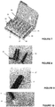
- a second embodiment of a container of the present invention will be described below with reference to Figures 7 to 10 .
- This container is received in a metal protective case 30 for manipulation and cryogenic storage.
- This container has an elongated shape, here rectangular, when viewed in plan view, defining a first longitudinal axis.
- This container has a plurality of storage chambers 31, here six (6), which are aligned at regular intervals from each other.
- the separation zone 32 separating two successive storage chambers 31 has a line 33 of least resistance, or pre-cutting, advantageously allowing easy separation of the storage rooms 31.
- Each storage chamber 31 has an elongated shape extending along a second longitudinal axis perpendicular to said first longitudinal axis.
- Two consecutive storage chambers 31 are also connected to their base, or lower part, by a portion 34 of conduit ensuring the fluid communication of the storage volumes of these storage rooms 31.
- the container also has a flexible tubing 35 placed on a side edge of the container and in fluid communication via each portion 34 of fluid communication conduit, with the storage volume of each of the storage chambers 31.
- This tubing 35 which serves as an inlet port of the container, ensures easy introduction into each storage chamber 31, the liquid medicine, cells such as stem cells or blood to be preserved by cryogenics.
- Each individual storage chamber 31 has a three-dimensional shape to ensure optimized storage, this shape having a longitudinal dimension (here height) in a first direction defined by said second longitudinal axis, which is both greater than the longitudinal dimension (here width) in a second direction defined by said first longitudinal axis and that the longitudinal dimension (here thickness) in a third direction perpendicular to the first direction and the second direction.
- each individual storage chamber 31 protrudes on either side of a median plane 36 defined by the stack of unconformed sheets but assembled together for example by welding.
- the two portions of each storage chamber 31 facing each other projecting from this median plane 36 are symmetrical, or constitute the image of one another, with respect to this median plane.
- each storage chamber thus comprises a flat bottom wall, or substantially flat, and a front wall, flat or substantially flat, which are both placed in said third direction, remote from said median plane 36 and while being distinct to define the storage volume of the chamber.
- These front and bottom walls are connected to the peripheral edge of the storage chamber 31 extending in the median plane 36, by side walls having a rounded or flat or substantially flat shape. In the latter case, these side walls can be placed at an angle.
- each storage chamber has a three-dimensional take-off port 37 which is sterile and empty.
- This sampling port 37 is separated from the storage volume of the corresponding storage chamber by a sealed junction line, for example obtained by welding, performed at a chimney 38 of the storage chamber 31.
- this sampling port 37 is configured to define a housing when it has been opened by transverse cutting, intended to receive a trocar (not shown) while ensuring the seal of its junction with the latter.
Landscapes
- Engineering & Computer Science (AREA)
- Mechanical Engineering (AREA)
- Life Sciences & Earth Sciences (AREA)
- Health & Medical Sciences (AREA)
- General Health & Medical Sciences (AREA)
- Environmental Sciences (AREA)
- Wood Science & Technology (AREA)
- Zoology (AREA)
- Dentistry (AREA)
- Basic Packing Technique (AREA)
- Medical Preparation Storing Or Oral Administration Devices (AREA)
- Hematology (AREA)
- Pharmacology & Pharmacy (AREA)
- Animal Behavior & Ethology (AREA)
- Public Health (AREA)
- Veterinary Medicine (AREA)
- Lining Or Joining Of Plastics Or The Like (AREA)
Claims (14)
- Verfahren zur Herstellung mindestens eines flexiblen Behälters (10) aus Plastikmaterial, wobei jeder Behälter (10) zwei gegenüberliegende getrennte Wände (12, 13) umfasst, die an mindestens einem Teil ihres Umfangs durch einen umlaufenden abgedichteten Rand (14) zusammengesetzt sind, wobei die getrennten Wände ein Stauvolumen des Behälters (10) definieren, dadurch gekennzeichnet, dass mindestens die folgenden Schritte durchgeführt werden:d) Realisieren aus einem einzigen fortlaufenden Film, der durch Extrudieren anhand eines Extruders gebildet wird, einer Stapelung aus zwei Folien (26, 27) aus Plastikmaterial am Ausgang des Extruders ausgehend von dem so erhaltenen Film, wobei die Folien (26, 27) aneinandergepresst werden, wobei die gegenüberliegenden Oberflächen dieser Folien (26, 27) ohne ein eine Schnittstelle bildendes Element direkt in Kontakt miteinander platziert werden,e) gleichzeitig Anpassen der so aneinandergepressten Folien (26, 27), um den mindestens einen Behälter (10) zu definieren, ohne diese zuvor getrennt zu haben, wobei mindestens jeder Behälter (10) teilweise gebildet wird, wobei die Folien (26, 27) in mindestens einem Teil der Zonen der Folien (26, 27) aneinandergepresst gehalten werden, die dazu bestimmt sind, den umlaufenden Rand (14) jedes Behälters (10) bei diesem Anpassen zu bilden, wobei das Anpassen durch Saugformen realisiert wird, indem man die Stapelung zwischen zwei Formteilen platziert, die voneinander beabstandet, und aneinander angelegt sein können, wodurch ein oder mehrere Hohlräume definiert werden, wobei mindestens einer dieser so gebildeten Hohlräume der Form und den äußeren Abmessungen eines herzustellenden Behälters (10) entspricht, wobei der mindestens eine Hohlraum im Bereich eines Abschnitts seiner Peripherie, der einem Abschnitt des umlaufenden Randes (14) des entsprechenden zu bildenden Behälters (10) entspricht, somit geschlossen ist, wobei mindestens einer der Formteile mehrere Öffnungen beinhaltet, die mit einer oder mehreren Pumpeinheiten verbunden sind,f) Abdichten mindestens eines Teils der Zonen der Folien (26, 27), die dazu bestimmt sind, den umlaufenden Rand (14) mindestens jedes Behälters (10) darzustellen.
- Verfahren nach Anspruch 1, dadurch gekennzeichnet, dass man einen zusätzlichen Schritt realisiert, der für jeden Behälter (10) darin besteht, zwischen die Folien (26, 27) mindestens ein Zugangselement (17) zu seinem Stauvolumen einzuführen, welches die Kommunikation von Fluid zwischen diesem Stauvolumen und der Außenseite ermöglicht.
- Verfahren nach Anspruch 1 oder 2, dadurch gekennzeichnet, dass vor dem Realisieren von Schritt b) mindestens teilweise die Zonen der Folien (26, 27) abgedichtet werden, die dazu bestimmt sind, den umlaufenden Rand (14) jedes Behälters (10) darzustellen.
- Verfahren nach einem der Ansprüche 1 bis 3, dadurch gekennzeichnet, dass im Schritt b) ebenfalls durch Anpassen der Folien (26, 27) eine Aufnahme für jedes Zugangselement (17) zu dem Stauvolumen des oder der Behälter (10) definiert wird, wobei jede Aufnahme konfiguriert ist, um das entsprechende Zugangselement (17) zu empfangen.
- Verfahren nach einem der Ansprüche 1 bis 3, dadurch gekennzeichnet, dass im Schritt b) ebenfalls durch Anpassen der Folien (26, 27) mindestens eine geschlossene Verlängerung, Zugangselement (17) genannt, des oder mindestens einiger der Behälter (10) definiert wird, wobei jede geschlossene Verlängerung ein Empfangsvolumen in Fluidkommunikation mit dem Stauvolumen des entsprechenden Behälters (10) definiert.
- Verfahren nach einem der Ansprüche 1 bis 5, dadurch gekennzeichnet, dass im Schritt b) ebenfalls durch Anpassen der Folien (26, 27) mindestens eine Leitung, oder Überbrückung (11) definiert wird, die mit einem umlaufenden Rand (14) mindestens eines Behälters (10) verbunden ist, um für seine Füllung zu sorgen, wobei die Leitung einen Innenkanal in Fluidkommunikation mit dem Stauvolumen des mindestens einen Behälters definiert.
- Verfahren nach Anspruch 6, dadurch gekennzeichnet, dass nach dem Füllen des oder der Behälter (10) der Rest der im Bereich des umlaufenden Randes (14) jedes Behälters (10) getrennten Folien (26, 27) abgedichtet wird, um jeden Behälter (10) zu schließen.
- Verfahren nach einem der Ansprüche 1 bis 7, dadurch gekennzeichnet, dass die Folien (26, 27) im Schritt b) auch in mindestens einer Zone, die sich von dem umlaufenden Rand (14) eines oder mehrerer Behälter (10) unterscheidet, aneinandergepresst gehalten werden, um das Innenvolumen des oder der entsprechenden Behälter(s) (10) zu unterteilen.
- Verfahren nach einem der Ansprüche 1 bis 8, dadurch gekennzeichnet, dass im Schritt b) gleichzeitig die beiden Folien (26, 27) in mindestens einem flexiblen Behälter (10) angepasst werden, ohne die Folien (26, 27) bei diesem Anpassen zu trennen.
- Verfahren nach Anspruch 9, dadurch gekennzeichnet, dass nach dem Schritt c) die Folien (26, 27) im Bereich des mindestens einen Behälters (10) durch Einführen des einzigen biologischen Materials, das dazu bestimmt ist, in diesem Behälter (10) enthalten zu sein, um dessen Kontamination zu beschränken, oder durch Zirkulieren eines kontrollierten gasförmigen Fluids, getrennt werden.
- Verfahren nach einem der Ansprüche 1 bis 10, dadurch gekennzeichnet, dass nach dem Schritt b) und vor dem Schritt c) ein zusätzlicher Schritt realisiert wird, der darin besteht, den mindestens einen Behälter (10) zu kühlen.
- Verfahren nach einem der Ansprüche 1 bis 11, dadurch gekennzeichnet, dass während mindestens der Schritte a) bis c) das Milieu, in dem die Stapelung der beiden Folien (26, 27) platziert wird, kontrolliert wird, um die Präsenz der Biocharge und von Teilchen zu beschränken, die die Biocharge transportieren könnten.
- Verfahren nach Anspruch 12, dadurch gekennzeichnet, dass man im Bereich der Vorrichtung oder der Maschine, die es ermöglicht, den Schritt b) zu realisieren, einen Luftstrom von oben nach unten zirkulieren lässt, um die Teilchen oder die Biocharge, die in der umgebenden Atmosphäre der Vorrichtung vorhanden sind, an den Boden zu pressen.
- Verfahren nach einem der Ansprüche 1 bis 13, dadurch gekennzeichnet, dass man die Stapelung entionisiert, um die elektrostatischen Lasten zu eliminieren.
Priority Applications (3)
| Application Number | Priority Date | Filing Date | Title |
|---|---|---|---|
| US14/683,225 US9757890B2 (en) | 2014-02-18 | 2015-04-10 | Method for producing at least one flexible plastic container |
| BR102015009487A BR102015009487A2 (pt) | 2015-02-16 | 2015-04-28 | processo de fabricação de pelo menos um recipiente flexível feito de matéria plástica |
| KR1020150065223A KR102502855B1 (ko) | 2014-02-18 | 2015-05-11 | 플라스틱 재료로 된 적어도 하나 이상의 가요성 용기의 제조 방법 |
Applications Claiming Priority (1)
| Application Number | Priority Date | Filing Date | Title |
|---|---|---|---|
| FR1451268A FR3017564B1 (fr) | 2014-02-18 | 2014-02-18 | Procede de fabrication d'au moins un recipient souple en matiere plastique |
Publications (2)
| Publication Number | Publication Date |
|---|---|
| EP2907649A1 EP2907649A1 (de) | 2015-08-19 |
| EP2907649B1 true EP2907649B1 (de) | 2019-09-04 |
Family
ID=51225621
Family Applications (1)
| Application Number | Title | Priority Date | Filing Date |
|---|---|---|---|
| EP15155232.0A Active EP2907649B1 (de) | 2014-02-18 | 2015-02-16 | Herstellungsverfahren mindestens eines flexiblen behälters aus plastikmaterial |
Country Status (3)
| Country | Link |
|---|---|
| EP (1) | EP2907649B1 (de) |
| KR (1) | KR102502855B1 (de) |
| FR (1) | FR3017564B1 (de) |
Families Citing this family (1)
| Publication number | Priority date | Publication date | Assignee | Title |
|---|---|---|---|---|
| US12239127B2 (en) | 2021-07-28 | 2025-03-04 | Sartorius Stedim North America Inc. | Thermal capacitors, systems, and methods for rapid freezing or heating of biological materials |
Family Cites Families (8)
| Publication number | Priority date | Publication date | Assignee | Title |
|---|---|---|---|---|
| GB1567337A (en) * | 1976-12-21 | 1980-05-14 | Aluminiumwerke Ag Rorschach | Method of and apparatus for producing a receptance |
| JPH074407B2 (ja) * | 1988-11-18 | 1995-01-25 | 凸版印刷株式会社 | 極低温耐性を有する袋状容器 |
| JPH0675588B2 (ja) * | 1989-07-14 | 1994-09-28 | 株式会社ニッショー | 引き裂き開封可能な血液バッグ |
| JP4882494B2 (ja) | 2006-05-08 | 2012-02-22 | ニプロ株式会社 | 凍結保存バイアルの包装体、凍結保存用キット及び凍結保存方法 |
| JP2008195443A (ja) | 2007-02-15 | 2008-08-28 | Nipro Corp | 冷凍保存容器 |
| TWI481534B (zh) * | 2008-05-16 | 2015-04-21 | Biosafe Sa | 製造供容納生物樣本用之袋的方法 |
| DE102011004173A1 (de) * | 2011-02-15 | 2012-08-16 | Huhtamaki Ronsberg Zn Der Huhtamaki Deutschland Gmbh & Co. Kg | Verpackung aus tiefgezogenem Beutel, Verfahren zur Herstellung derselben und Verpackung Halbzeug |
| JP6157050B2 (ja) | 2011-06-22 | 2017-07-05 | 株式会社ジェイ・エム・エス | 細胞凍結保存容器 |
-
2014
- 2014-02-18 FR FR1451268A patent/FR3017564B1/fr active Active
-
2015
- 2015-02-16 EP EP15155232.0A patent/EP2907649B1/de active Active
- 2015-05-11 KR KR1020150065223A patent/KR102502855B1/ko active Active
Non-Patent Citations (1)
| Title |
|---|
| None * |
Also Published As
| Publication number | Publication date |
|---|---|
| KR20160100776A (ko) | 2016-08-24 |
| FR3017564B1 (fr) | 2016-09-16 |
| EP2907649A1 (de) | 2015-08-19 |
| FR3017564A1 (fr) | 2015-08-21 |
| KR102502855B1 (ko) | 2023-02-23 |
Similar Documents
| Publication | Publication Date | Title |
|---|---|---|
| EP2645981B1 (de) | Beutel zum verteilen eines produkts zur biopharmazeutischen verwendung im allgemeinen zustand einer flüssigkeit oder paste über mehrere auslassports | |
| CA2841030C (fr) | Kit pour la conservation d'un produit biologique comprenant une poche tridimensionnelle et une enveloppe tridimensionnelle adaptee | |
| EP2139538B1 (de) | Mit einem versetzten einlass- und/oder auslasselement ausgestattete filtrierungseinheit für eine biologische flüssigkeit | |
| EP2598412B1 (de) | Einwegsverpackung | |
| EP2931439A1 (de) | Verpackung für eine sprühbare kosmetische flüssigkeit mit einem flexiblen beutel und einem aussenrahmen | |
| EP2999450B1 (de) | Stopfen für verbinder für einen infusionsbeutel | |
| EP2326363A2 (de) | Filtrationsgerät für eine flüssigkeit mit dichtungsdiskontinuität | |
| EP4140466A1 (de) | Flexibler plastikbehälter für eine flüssigkeit | |
| EP2542474A1 (de) | Verfahren zur herstellung von sterilen flexiblen mit einem produkt gefüllten beuteln, im besonderen mit einer therapeutischen flüssigkeit, und entsprechende beutel | |
| EP2907649B1 (de) | Herstellungsverfahren mindestens eines flexiblen behälters aus plastikmaterial | |
| EP4031231B1 (de) | Einstückiger verbinder für einen flexiblen infusionsbeutel | |
| EP2999449A1 (de) | Basis für einen verbinder für einen infusionsbeutel | |
| EP3541344B1 (de) | Medizinischer beutel mit zwei kammern und mit einer lasche | |
| EP2193775B1 (de) | Flexibler Behälter für den medizinischen Einsatz | |
| FR3027220A1 (fr) | Ensemble pour le stockage de produits a usage medical | |
| FR2932989A1 (fr) | Unite de filtration pourvue d'un compartiment annexe | |
| EP0696958B1 (de) | Hochfrequenzschweisselektrode für medizinisch genutzte mehrfachkammerbeutel aus einer kunststofffolie und aus diesem material hergestellte beutel | |
| BE1020600A3 (fr) | Module jetable pour dispositif de synthese de radioisotopes et procede de fabrication dudit module. | |
| FR2814968A1 (fr) | Dispositif distributeur avec buse integrale et capuchon | |
| FR3049467A1 (fr) | Port, systeme de distribution comprenant un tel port, et procede de fabrication | |
| WO2003011713A1 (fr) | Dispositif a recipient rigide et poche cylindrique souple pour le conditionnement de fluides. | |
| WO2025104399A1 (fr) | Ensemble de récipients emballés et procédé d'emballage de récipients | |
| WO2023020858A1 (fr) | Emballage étanche d'un produit alimentaire fluide | |
| FR2814440A1 (fr) | Emballage souple a ouverture facile, procede et installation de fabrication | |
| FR2978426A1 (fr) | Procede de remplissage d'un recipient souple |
Legal Events
| Date | Code | Title | Description |
|---|---|---|---|
| PUAI | Public reference made under article 153(3) epc to a published international application that has entered the european phase |
Free format text: ORIGINAL CODE: 0009012 |
|
| AK | Designated contracting states |
Kind code of ref document: A1 Designated state(s): AL AT BE BG CH CY CZ DE DK EE ES FI FR GB GR HR HU IE IS IT LI LT LU LV MC MK MT NL NO PL PT RO RS SE SI SK SM TR |
|
| AX | Request for extension of the european patent |
Extension state: BA ME |
|
| 17P | Request for examination filed |
Effective date: 20160126 |
|
| RBV | Designated contracting states (corrected) |
Designated state(s): AL AT BE BG CH CY CZ DE DK EE ES FI FR GB GR HR HU IE IS IT LI LT LU LV MC MK MT NL NO PL PT RO RS SE SI SK SM TR |
|
| STAA | Information on the status of an ep patent application or granted ep patent |
Free format text: STATUS: EXAMINATION IS IN PROGRESS |
|
| 17Q | First examination report despatched |
Effective date: 20180223 |
|
| GRAP | Despatch of communication of intention to grant a patent |
Free format text: ORIGINAL CODE: EPIDOSNIGR1 |
|
| STAA | Information on the status of an ep patent application or granted ep patent |
Free format text: STATUS: GRANT OF PATENT IS INTENDED |
|
| INTG | Intention to grant announced |
Effective date: 20190410 |
|
| GRAS | Grant fee paid |
Free format text: ORIGINAL CODE: EPIDOSNIGR3 |
|
| GRAA | (expected) grant |
Free format text: ORIGINAL CODE: 0009210 |
|
| STAA | Information on the status of an ep patent application or granted ep patent |
Free format text: STATUS: THE PATENT HAS BEEN GRANTED |
|
| AK | Designated contracting states |
Kind code of ref document: B1 Designated state(s): AL AT BE BG CH CY CZ DE DK EE ES FI FR GB GR HR HU IE IS IT LI LT LU LV MC MK MT NL NO PL PT RO RS SE SI SK SM TR |
|
| REG | Reference to a national code |
Ref country code: GB Ref legal event code: FG4D Free format text: NOT ENGLISH |
|
| REG | Reference to a national code |
Ref country code: CH Ref legal event code: EP |
|
| REG | Reference to a national code |
Ref country code: AT Ref legal event code: REF Ref document number: 1174759 Country of ref document: AT Kind code of ref document: T Effective date: 20190915 |
|
| REG | Reference to a national code |
Ref country code: DE Ref legal event code: R096 Ref document number: 602015037010 Country of ref document: DE |
|
| REG | Reference to a national code |
Ref country code: IE Ref legal event code: FG4D Free format text: LANGUAGE OF EP DOCUMENT: FRENCH |
|
| REG | Reference to a national code |
Ref country code: NL Ref legal event code: FP |
|
| REG | Reference to a national code |
Ref country code: LT Ref legal event code: MG4D |
|
| PG25 | Lapsed in a contracting state [announced via postgrant information from national office to epo] |
Ref country code: HR Free format text: LAPSE BECAUSE OF FAILURE TO SUBMIT A TRANSLATION OF THE DESCRIPTION OR TO PAY THE FEE WITHIN THE PRESCRIBED TIME-LIMIT Effective date: 20190904 Ref country code: LT Free format text: LAPSE BECAUSE OF FAILURE TO SUBMIT A TRANSLATION OF THE DESCRIPTION OR TO PAY THE FEE WITHIN THE PRESCRIBED TIME-LIMIT Effective date: 20190904 Ref country code: NO Free format text: LAPSE BECAUSE OF FAILURE TO SUBMIT A TRANSLATION OF THE DESCRIPTION OR TO PAY THE FEE WITHIN THE PRESCRIBED TIME-LIMIT Effective date: 20191204 Ref country code: FI Free format text: LAPSE BECAUSE OF FAILURE TO SUBMIT A TRANSLATION OF THE DESCRIPTION OR TO PAY THE FEE WITHIN THE PRESCRIBED TIME-LIMIT Effective date: 20190904 Ref country code: SE Free format text: LAPSE BECAUSE OF FAILURE TO SUBMIT A TRANSLATION OF THE DESCRIPTION OR TO PAY THE FEE WITHIN THE PRESCRIBED TIME-LIMIT Effective date: 20190904 Ref country code: BG Free format text: LAPSE BECAUSE OF FAILURE TO SUBMIT A TRANSLATION OF THE DESCRIPTION OR TO PAY THE FEE WITHIN THE PRESCRIBED TIME-LIMIT Effective date: 20191204 |
|
| PG25 | Lapsed in a contracting state [announced via postgrant information from national office to epo] |
Ref country code: RS Free format text: LAPSE BECAUSE OF FAILURE TO SUBMIT A TRANSLATION OF THE DESCRIPTION OR TO PAY THE FEE WITHIN THE PRESCRIBED TIME-LIMIT Effective date: 20190904 Ref country code: LV Free format text: LAPSE BECAUSE OF FAILURE TO SUBMIT A TRANSLATION OF THE DESCRIPTION OR TO PAY THE FEE WITHIN THE PRESCRIBED TIME-LIMIT Effective date: 20190904 Ref country code: ES Free format text: LAPSE BECAUSE OF FAILURE TO SUBMIT A TRANSLATION OF THE DESCRIPTION OR TO PAY THE FEE WITHIN THE PRESCRIBED TIME-LIMIT Effective date: 20190904 Ref country code: AL Free format text: LAPSE BECAUSE OF FAILURE TO SUBMIT A TRANSLATION OF THE DESCRIPTION OR TO PAY THE FEE WITHIN THE PRESCRIBED TIME-LIMIT Effective date: 20190904 Ref country code: GR Free format text: LAPSE BECAUSE OF FAILURE TO SUBMIT A TRANSLATION OF THE DESCRIPTION OR TO PAY THE FEE WITHIN THE PRESCRIBED TIME-LIMIT Effective date: 20191205 |
|
| REG | Reference to a national code |
Ref country code: AT Ref legal event code: MK05 Ref document number: 1174759 Country of ref document: AT Kind code of ref document: T Effective date: 20190904 |
|
| REG | Reference to a national code |
Ref country code: CH Ref legal event code: NV Representative=s name: MICHELI AND CIE SA, CH |
|
| PG25 | Lapsed in a contracting state [announced via postgrant information from national office to epo] |
Ref country code: AT Free format text: LAPSE BECAUSE OF FAILURE TO SUBMIT A TRANSLATION OF THE DESCRIPTION OR TO PAY THE FEE WITHIN THE PRESCRIBED TIME-LIMIT Effective date: 20190904 Ref country code: PT Free format text: LAPSE BECAUSE OF FAILURE TO SUBMIT A TRANSLATION OF THE DESCRIPTION OR TO PAY THE FEE WITHIN THE PRESCRIBED TIME-LIMIT Effective date: 20200106 Ref country code: PL Free format text: LAPSE BECAUSE OF FAILURE TO SUBMIT A TRANSLATION OF THE DESCRIPTION OR TO PAY THE FEE WITHIN THE PRESCRIBED TIME-LIMIT Effective date: 20190904 Ref country code: RO Free format text: LAPSE BECAUSE OF FAILURE TO SUBMIT A TRANSLATION OF THE DESCRIPTION OR TO PAY THE FEE WITHIN THE PRESCRIBED TIME-LIMIT Effective date: 20190904 Ref country code: EE Free format text: LAPSE BECAUSE OF FAILURE TO SUBMIT A TRANSLATION OF THE DESCRIPTION OR TO PAY THE FEE WITHIN THE PRESCRIBED TIME-LIMIT Effective date: 20190904 |
|
| PG25 | Lapsed in a contracting state [announced via postgrant information from national office to epo] |
Ref country code: IS Free format text: LAPSE BECAUSE OF FAILURE TO SUBMIT A TRANSLATION OF THE DESCRIPTION OR TO PAY THE FEE WITHIN THE PRESCRIBED TIME-LIMIT Effective date: 20200224 Ref country code: SM Free format text: LAPSE BECAUSE OF FAILURE TO SUBMIT A TRANSLATION OF THE DESCRIPTION OR TO PAY THE FEE WITHIN THE PRESCRIBED TIME-LIMIT Effective date: 20190904 Ref country code: CZ Free format text: LAPSE BECAUSE OF FAILURE TO SUBMIT A TRANSLATION OF THE DESCRIPTION OR TO PAY THE FEE WITHIN THE PRESCRIBED TIME-LIMIT Effective date: 20190904 Ref country code: SK Free format text: LAPSE BECAUSE OF FAILURE TO SUBMIT A TRANSLATION OF THE DESCRIPTION OR TO PAY THE FEE WITHIN THE PRESCRIBED TIME-LIMIT Effective date: 20190904 |
|
| REG | Reference to a national code |
Ref country code: DE Ref legal event code: R097 Ref document number: 602015037010 Country of ref document: DE |
|
| PLBE | No opposition filed within time limit |
Free format text: ORIGINAL CODE: 0009261 |
|
| STAA | Information on the status of an ep patent application or granted ep patent |
Free format text: STATUS: NO OPPOSITION FILED WITHIN TIME LIMIT |
|
| PG2D | Information on lapse in contracting state deleted |
Ref country code: IS |
|
| PG25 | Lapsed in a contracting state [announced via postgrant information from national office to epo] |
Ref country code: DK Free format text: LAPSE BECAUSE OF FAILURE TO SUBMIT A TRANSLATION OF THE DESCRIPTION OR TO PAY THE FEE WITHIN THE PRESCRIBED TIME-LIMIT Effective date: 20190904 Ref country code: IS Free format text: LAPSE BECAUSE OF FAILURE TO SUBMIT A TRANSLATION OF THE DESCRIPTION OR TO PAY THE FEE WITHIN THE PRESCRIBED TIME-LIMIT Effective date: 20200105 |
|
| 26N | No opposition filed |
Effective date: 20200605 |
|
| PG25 | Lapsed in a contracting state [announced via postgrant information from national office to epo] |
Ref country code: SI Free format text: LAPSE BECAUSE OF FAILURE TO SUBMIT A TRANSLATION OF THE DESCRIPTION OR TO PAY THE FEE WITHIN THE PRESCRIBED TIME-LIMIT Effective date: 20190904 |
|
| REG | Reference to a national code |
Ref country code: BE Ref legal event code: MM Effective date: 20200229 |
|
| PG25 | Lapsed in a contracting state [announced via postgrant information from national office to epo] |
Ref country code: MC Free format text: LAPSE BECAUSE OF FAILURE TO SUBMIT A TRANSLATION OF THE DESCRIPTION OR TO PAY THE FEE WITHIN THE PRESCRIBED TIME-LIMIT Effective date: 20190904 Ref country code: LU Free format text: LAPSE BECAUSE OF NON-PAYMENT OF DUE FEES Effective date: 20200216 |
|
| PG25 | Lapsed in a contracting state [announced via postgrant information from national office to epo] |
Ref country code: IE Free format text: LAPSE BECAUSE OF NON-PAYMENT OF DUE FEES Effective date: 20200216 |
|
| PG25 | Lapsed in a contracting state [announced via postgrant information from national office to epo] |
Ref country code: BE Free format text: LAPSE BECAUSE OF NON-PAYMENT OF DUE FEES Effective date: 20200229 |
|
| PG25 | Lapsed in a contracting state [announced via postgrant information from national office to epo] |
Ref country code: TR Free format text: LAPSE BECAUSE OF FAILURE TO SUBMIT A TRANSLATION OF THE DESCRIPTION OR TO PAY THE FEE WITHIN THE PRESCRIBED TIME-LIMIT Effective date: 20190904 Ref country code: MT Free format text: LAPSE BECAUSE OF FAILURE TO SUBMIT A TRANSLATION OF THE DESCRIPTION OR TO PAY THE FEE WITHIN THE PRESCRIBED TIME-LIMIT Effective date: 20190904 Ref country code: CY Free format text: LAPSE BECAUSE OF FAILURE TO SUBMIT A TRANSLATION OF THE DESCRIPTION OR TO PAY THE FEE WITHIN THE PRESCRIBED TIME-LIMIT Effective date: 20190904 |
|
| PG25 | Lapsed in a contracting state [announced via postgrant information from national office to epo] |
Ref country code: MK Free format text: LAPSE BECAUSE OF FAILURE TO SUBMIT A TRANSLATION OF THE DESCRIPTION OR TO PAY THE FEE WITHIN THE PRESCRIBED TIME-LIMIT Effective date: 20190904 |
|
| P01 | Opt-out of the competence of the unified patent court (upc) registered |
Effective date: 20230714 |
|
| PGFP | Annual fee paid to national office [announced via postgrant information from national office to epo] |
Ref country code: NL Payment date: 20250128 Year of fee payment: 11 |
|
| PGFP | Annual fee paid to national office [announced via postgrant information from national office to epo] |
Ref country code: DE Payment date: 20250212 Year of fee payment: 11 |
|
| PGFP | Annual fee paid to national office [announced via postgrant information from national office to epo] |
Ref country code: CH Payment date: 20250301 Year of fee payment: 11 |
|
| PGFP | Annual fee paid to national office [announced via postgrant information from national office to epo] |
Ref country code: FR Payment date: 20250115 Year of fee payment: 11 |
|
| PGFP | Annual fee paid to national office [announced via postgrant information from national office to epo] |
Ref country code: IT Payment date: 20250207 Year of fee payment: 11 Ref country code: GB Payment date: 20250221 Year of fee payment: 11 |