EP2907863B1 - Verfahren zur herstellung von phosphor - Google Patents
Verfahren zur herstellung von phosphor Download PDFInfo
- Publication number
- EP2907863B1 EP2907863B1 EP13846131.4A EP13846131A EP2907863B1 EP 2907863 B1 EP2907863 B1 EP 2907863B1 EP 13846131 A EP13846131 A EP 13846131A EP 2907863 B1 EP2907863 B1 EP 2907863B1
- Authority
- EP
- European Patent Office
- Prior art keywords
- phosphor
- nitride
- strontium
- mass
- powder
- Prior art date
- Legal status (The legal status is an assumption and is not a legal conclusion. Google has not performed a legal analysis and makes no representation as to the accuracy of the status listed.)
- Active
Links
Images
Classifications
-
- C—CHEMISTRY; METALLURGY
- C01—INORGANIC CHEMISTRY
- C01B—NON-METALLIC ELEMENTS; COMPOUNDS THEREOF; METALLOIDS OR COMPOUNDS THEREOF NOT COVERED BY SUBCLASS C01C
- C01B21/00—Nitrogen; Compounds thereof
- C01B21/082—Compounds containing nitrogen and non-metals and optionally metals
-
- C—CHEMISTRY; METALLURGY
- C01—INORGANIC CHEMISTRY
- C01B—NON-METALLIC ELEMENTS; COMPOUNDS THEREOF; METALLOIDS OR COMPOUNDS THEREOF NOT COVERED BY SUBCLASS C01C
- C01B21/00—Nitrogen; Compounds thereof
- C01B21/06—Binary compounds of nitrogen with metals, with silicon, or with boron, or with carbon, i.e. nitrides; Compounds of nitrogen with more than one metal, silicon or boron
- C01B21/0615—Binary compounds of nitrogen with metals, with silicon, or with boron, or with carbon, i.e. nitrides; Compounds of nitrogen with more than one metal, silicon or boron with transition metals other than titanium, zirconium or hafnium
- C01B21/0627—Binary compounds of nitrogen with metals, with silicon, or with boron, or with carbon, i.e. nitrides; Compounds of nitrogen with more than one metal, silicon or boron with transition metals other than titanium, zirconium or hafnium with one or more rare earth metals
-
- C—CHEMISTRY; METALLURGY
- C01—INORGANIC CHEMISTRY
- C01B—NON-METALLIC ELEMENTS; COMPOUNDS THEREOF; METALLOIDS OR COMPOUNDS THEREOF NOT COVERED BY SUBCLASS C01C
- C01B21/00—Nitrogen; Compounds thereof
- C01B21/082—Compounds containing nitrogen and non-metals and optionally metals
- C01B21/0821—Oxynitrides of metals, boron or silicon
- C01B21/0826—Silicon aluminium oxynitrides, i.e. sialons
-
- C—CHEMISTRY; METALLURGY
- C09—DYES; PAINTS; POLISHES; NATURAL RESINS; ADHESIVES; COMPOSITIONS NOT OTHERWISE PROVIDED FOR; APPLICATIONS OF MATERIALS NOT OTHERWISE PROVIDED FOR
- C09K—MATERIALS FOR MISCELLANEOUS APPLICATIONS, NOT PROVIDED FOR ELSEWHERE
- C09K11/00—Luminescent materials, e.g. electroluminescent or chemiluminescent
- C09K11/08—Luminescent materials, e.g. electroluminescent or chemiluminescent containing inorganic luminescent materials
- C09K11/64—Luminescent materials, e.g. electroluminescent or chemiluminescent containing inorganic luminescent materials containing aluminium
- C09K11/646—Silicates
-
- C—CHEMISTRY; METALLURGY
- C09—DYES; PAINTS; POLISHES; NATURAL RESINS; ADHESIVES; COMPOSITIONS NOT OTHERWISE PROVIDED FOR; APPLICATIONS OF MATERIALS NOT OTHERWISE PROVIDED FOR
- C09K—MATERIALS FOR MISCELLANEOUS APPLICATIONS, NOT PROVIDED FOR ELSEWHERE
- C09K11/00—Luminescent materials, e.g. electroluminescent or chemiluminescent
- C09K11/08—Luminescent materials, e.g. electroluminescent or chemiluminescent containing inorganic luminescent materials
- C09K11/77—Luminescent materials, e.g. electroluminescent or chemiluminescent containing inorganic luminescent materials containing rare earth metals
- C09K11/7728—Luminescent materials, e.g. electroluminescent or chemiluminescent containing inorganic luminescent materials containing rare earth metals containing europium
- C09K11/77348—Silicon Aluminium Nitrides or Silicon Aluminium Oxynitrides
-
- C—CHEMISTRY; METALLURGY
- C01—INORGANIC CHEMISTRY
- C01P—INDEXING SCHEME RELATING TO STRUCTURAL AND PHYSICAL ASPECTS OF SOLID INORGANIC COMPOUNDS
- C01P2002/00—Crystal-structural characteristics
- C01P2002/50—Solid solutions
-
- C—CHEMISTRY; METALLURGY
- C01—INORGANIC CHEMISTRY
- C01P—INDEXING SCHEME RELATING TO STRUCTURAL AND PHYSICAL ASPECTS OF SOLID INORGANIC COMPOUNDS
- C01P2002/00—Crystal-structural characteristics
- C01P2002/70—Crystal-structural characteristics defined by measured X-ray, neutron or electron diffraction data
- C01P2002/72—Crystal-structural characteristics defined by measured X-ray, neutron or electron diffraction data by d-values or two theta-values, e.g. as X-ray diagram
-
- C—CHEMISTRY; METALLURGY
- C01—INORGANIC CHEMISTRY
- C01P—INDEXING SCHEME RELATING TO STRUCTURAL AND PHYSICAL ASPECTS OF SOLID INORGANIC COMPOUNDS
- C01P2002/00—Crystal-structural characteristics
- C01P2002/80—Crystal-structural characteristics defined by measured data other than those specified in group C01P2002/70
- C01P2002/84—Crystal-structural characteristics defined by measured data other than those specified in group C01P2002/70 by UV- or VIS- data
Definitions
- the present invention relates to a method for producing a phosphor. More specifically, it relates to a method for producing a phosphor that contains a host crystal having a crystal structure substantially identical with that of (Sr,Ca)AlSiN 3 crystal, and that absorbs light from a light-emitting device such as LED and emits red light.
- White LEDs are devices that emits white light in combination of a semiconductor light-emitting device and a phosphor and a typical known example thereof is a combination of a blue LED and a YAG (Yttrium Aluminum Garnet) yellow phosphor.
- YAG phosphors which contain a smaller amount of red light-emitting component, have problems that they are inferior in color rendering properties for use in illumination application, and lose their color reproducibility when used as a backlight for image display devices such as liquid-crystal display devices.
- (Sr,Ca)AlSiN 3 -based nitride phosphors which are obtained by substituting part of the Ca atoms in an Eu 2+ -activated CaAlSiN 3 -based nitride phosphor with Sr, emits a light having a wavelength shorter than that of the CaAlSiN 3 -based nitride phosphors and give better visual sensitivity of the color of the emitted light. Thus, they are promising as a red phosphor for high-brightness white LEDs.
- an object of the present invention is to provide a method for producing, by using nitride raw materials, a phosphor that gives a high-reliability (SrCa)AlSiN 3 -based nitride phosphor at a productivity higher than before.
- the method for producing a phosphor according to the present invention is a method for producing a phosphor, the host crystal thereof having a crystal structure substantially identical with that of (Sr,Ca)AlSiN 3 crystal, comprising a mixing step of mixing raw materials and a calcining step of calcining the mixture obtained in the mixing step, wherein a strontium nitride containing SrN, Sr 2 N, or the mixture thereof as the main crystalline phase, as determined by crystalline phase analysis by powder X-ray diffractometry, and having a nitrogen content of 5 to 12 mass % is used as part of the raw materials.
- the method for producing a phosphor according to the present invention may comprise, before the mixing step, a classifying step of reducing the maximum diameter of the strontium nitride, part of the raw material, to 300 ⁇ m or less.
- a strontium nitride having an oxygen content of 0.2 to 1 mass % may be used partially as the raw material.
- the raw materials for use may be a strontium nitride powder, a calcium nitride powder, a silicon nitride powder, an aluminum nitride powder, and a europium compound powder.
- the raw material mixture may be calcined under a temperature condition of 1500 to 1900°C in nitrogen atmosphere.
- the method for producing a phosphor in the present embodiment gives a phosphor, the host crystal thereof having a crystal structure substantially identical with that of (Sr,Ca)AlSiN 3 crystal, by processing at least in a mixing step of mixing the raw materials and a calcining step of calcining the mixture obtained in the mixing step.
- a strontium nitride containing a main crystalline phase, as determined by crystalline phase analysis by powder X-ray diffractometry, of SrN, Sr 2 N, or the mixture thereof and having a nitrogen content of 5 to 12 mass % is then used as part of the raw materials.
- the (Sr,Ca)AlSiN 3 crystalline phase has a skeletal structure of (Si,Al)-N 4 tetrahedrons bound to each other and a crystal structure containing Sr and Ca atoms located in the gap. Substitution of part of the Sr 2+ or Ca 2+ ions located in the gap of skeletal structure of the (Sr,Ca)AlSiN 3 crystal with Eu 2+ ions, which function as an emission center, gives a red phosphor.
- the Eu content in the raw material is preferably 0.01 to 0.3 atom %.
- the Eu content in the raw material is more preferably in the range of 0.04 to 0.2 atom %, and still more preferably in the range of 0.06 to 0.15 atom %.
- the phosphor obtained by the production method in the present embodiment contains a trace amount of oxygen (O) as an inevitable contaminant.
- the compositional parameters of the phosphor such as contents of Ca and Sr elements, Si/Al ratio, and N/O ratio, are regulated to make the phosphor retain its crystal structure and electrically neutralized as a whole.
- strontium nitride On a card in a database of X-ray diffraction pattern for use in crystal structure analysis, JCPDS (Joint Committee on Power Diffraction Standards), Sr 2 N, SrN, SrN 2 , and Sr 4 N 3 are listed as examples of strontium nitride.
- the raw material is preferably a strontium nitride containing SrN, Sr 2 N, or the mixture thereof, which are superior in stability among the various strontium nitrides, as the main crystalline phase.
- Crystalline phase analysis of the strontium nitride can be performed by X-ray diffractometry.
- the crystal structure of a strontium nitride can be identified, for example, by comparing the X-ray diffraction pattern thereof with that on the JCPDS card described above.
- the strontium nitride used as part of the raw material has a nitrogen content of 5 to 12 mass %.
- the nitrogen content of the strontium nitride is less than 5 mass %, reaction heat caused by nitridization of the raw material becomes larger in the calcining step described below, because strontium nitridization is insufficient.
- there are produced a greater amount of aggregated bulky calcined powder leading to deterioration of the yield during the post-calcination screening performed for classification to a suitable particle diameter or less.
- the strontium nitride used as part of the raw material preferably has an oxygen content of 0.2 to 1 mass %.
- An excessively large oxygen content in the strontium nitride leads to deterioration of the fluorescence intensity of the phosphor finally obtained and it is technically difficult to obtain a strontium nitride having an extremely low oxygen content.
- the raw materials are mixed, for example, by a dry mixing method or by a method of wet-mixing the raw materials in an inactive solvent that does not react substantially with the components in the raw materials and then removing the solvent.
- the mixing apparatuses include type-V mixers, rocking mixers, ball mills, and vibrating mills.
- the raw materials for use in the mixing step are preferably a strontium nitride powder, a calcium nitride powder, a silicon nitride powder, an aluminum nitride powder, and a europium compound powder for elimination, as much as possible, of the elements other than those constituting the desired phosphor. Because strontium nitride and calcium nitride are instable in air, mixing thereof is preferably carried out in a glove box under inert atmosphere, as hydrolysis and oxidation thereof may affect the properties of the phosphor.
- the composition of the raw materials (element number ratio), i.e., (Sr+Ca+Eu): Al: Si, is preferably 1: 1: 1.
- the element number ratio of the (Sr,Ca)AlSiN 3 -based nitride phosphor obtained after calcination may not be identical with its stoichiometric composition.
- the difference between the stoichiometric composition during mixing and the stoichiometric composition after calcination is caused by deterioration in the luminous efficiency caused by crystal defect formed during calcination. It is thus desired to adjust the composition of the raw material by estimating the change of stoichiometric composition by calcination.
- the mixture obtained in the mixing step (raw material powder mixture) is placed in a calcination container.
- the material of the calcination container is preferably boron nitride that is stable even when heated under nitrogen environment at high temperature and less reactive with the mixture and the reaction product.
- the calcining step it is preferable to heat the mixture under a temperature condition of 1500 to 1900°C in a nitrogen atmosphere.
- An excessively low calcination temperature leads to increase of the amount of the unreacted residual, while an excessively high calcination temperature leads to decomposition of the main phase that has the crystal structure identical with that of (Sr,Ca)AlSiN 3 .
- the calcination period is preferably 1 to 24 hours, for reduction of unreacted materials and for prevention of insufficient particle growth and deterioration in productivity.
- the decomposition temperature of the phosphor becomes higher when the pressure of the atmosphere in the calcining step is higher, it is preferably less than 1 MPa, when the industrial productivity is taken into consideration.
- the method for producing a phosphor in the present embodiment it is preferable to carry out, before the mixing step, a classifying step of reducing the maximum diameter of the strontium nitride, part of the raw material, to 300 ⁇ m or less. It is because, if strontium nitride having an excessively large particle diameter is contained in the raw material, the phosphor is prepared heterogeneously during calcination at high temperature, leading to fluctuation of fluorescence intensity and generation of heterogeneous phases.
- the strontium nitride is preferably classified by a method of passing it through a sieve having an opening of 300 ⁇ m or less.
- the method for producing a phosphor in the present embodiment preferably comprises additionally an acid-treatment step for removal of the impurities in the phosphor produced and an annealing step for improvement of crystallinity.
- the method for producing a phosphor in the present embodiment which uses a strontium nitride containing SrN, Sr 2 N, or the mixture thereof as the main crystalline phase and having a nitrogen content of 5 to 12 mass %, suppresses favorably the reaction heat by nitridization of the raw materials and reduces generation of aggregated bulky calcined powder.
- a phosphor suitable for use in LED having a particle diameter in the range of 5 to 30 ⁇ m.
- the particle diameter of the phosphor can be controlled more effectively by crushing, pulverization, or classification.
- the crystalline phase present in the phosphor is preferably a single crystalline phase with fewer heterogeneous phase.
- the content of heterogeneous-phase crystal is preferably 10 mass % or less.
- the content of heterogeneous phase (mass %) can be determined from the diffraction intensity of the other crystalline phases relative to the maximum diffraction intensity of the crystalline phase in analysis by powder X-ray diffractometry.
- the method for producing a phosphor in the present embodiment gives a phosphor containing Sr 2 Si 5 N 8 and AlN, which are heterogeneous phases identified by Rietveld analysis using a X-ray diffraction apparatus, respectively in an amount by mass of 10 mass % or less.
- the phosphor obtained by the production method in the present embodiment can be used in light-emitting devices having a light source and a phosphor.
- the phosphor shows an emission characteristic having a fluorescence peak at a wavelength of 620 to 650 nm, when irradiated with a UV or visible light having a wavelength of 350 to 500 nm as the excitation source, it is possible to obtain white light in combination with a light source such as ultraviolet LED or blue LED or, additionally as needed, in combination with a green to yellow phosphor and/or a blue phosphor.
- the phosphor obtained by the production method in the present embodiment has a crystal structure substantially identical with that of the (Sr,Ca)AlSiN 3 crystalline phase that is superior in stability, it is resistant to deterioration in brightness at high temperature and degradation when exposed to high temperature and superior in heat resistance and long-term stability under oxidative atmosphere and humid environment.
- a light-emitting device containing the phosphor is resistant to deterioration in brightness and color change and gives high brightness and longer life.
- Metal strontium 38-0074 grade, purity: 99.9%, produced by Strem Chemicals Inc. was placed in an alumina boat in a glove box under nitrogen-substituted atmosphere; the alumina boat was placed in a quartz pipe; both ends of the quartz pipe were sealed; and the quartz pipe having the metal strontium therein was withdrawn from the glove box.
- the quartz pipe was placed in a solenoidal furnace; nitrogen gas pipes were connected to the quartz pipe; and the quartz pipe and the nitrogen gas lines were evacuated under vacuum.
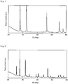
- the strontium nitride obtained was subjected to powder X-ray diffraction with CuK ⁇ X-rays on a X-ray diffraction apparatus (Ultima IV, manufactured by Rigaku Corporation).
- the X-ray diffraction pattern obtained is shown in Figure 1 .
- the X-ray diffraction pattern shown in Figure 1 was compared with that in the JCPDS card, showing that the powder has the crystalline phase identical with SrN crystalline phase.
- the nitrogen and oxygen contents in strontium nitride were determined on an oxygen nitrogen analyzer (EMGA-920, manufactured by Horiba, Ltd.) The nitrogen content was found to be 11.0 mass % and the oxygen content was found to be 0.23 mass %.
- Raw materials used were an ⁇ -silicon nitride powder (produced by Ube Industries, Ltd., SN-E10 grade, oxygen content 1.0 mass %): 52.2 mass %, an aluminum nitride powder (produced by Tokuyama Corporation, E grade, oxygen content: 0.8 mass %): 45.8 mass %, and europium oxide (produced by Shin-Etsu Chemical Co., Ltd., RU grade): 2.0 mass %.
- the raw materials were mixed in a ball mill, as ethanol was used as the solvent. During the ball mill mixing, a nylon pot and silicon nitride balls were used. After the ball mill mixing, the solvent was removed by drying, and the product was screened with a sieve having an opening of 75 ⁇ m for removal of aggregates.
- the raw materials mixed and classified, the strontium nitride prepared by the method described above, and a calcium nitride powder (produced by Materion Corporation, purity: 99%, particle diameter: 75 ⁇ m or less, oxygen content: 0.6 mass %) were transferred into a glove box under nitrogen-substituted atmosphere and mixed with a mortar.
- the mixture obtained after mixing in the mortar was filled in a glove box into a cylindrical boron nitride container (produced by DENKI KAGAKU KOGYO KABUSHIKI KAISHA, N-1 grade) with a cap; the container was withdrawn from the glove box and placed in an electric furnace with carbon heater and the electric furnace was vacuum-evacuated sufficiently to a pressure of 0.1 Pa or less.
- the mixture was heated as the container was held vacuum-evacuated; nitrogen gas was introduced when the temperature reached 600°C, and the atmospheric pressure in the furnace was adjusted to 0.9 MPa.
- the mixture was heated further to 1800°C after introduction of the nitrogen gas and calcined at 1800°C for 4 hours, to give a phosphor.
- the phosphor obtained was cooled to normal temperature.
- the phosphor cooled to normal temperature was crushed in a ball mill and the powder passing a vibration sieve having an opening of 45 ⁇ m was fractionated. The yield during classification was 98 mass %.
- the phosphor after classification was washed with water and finer particles were removed by additional classification.
- Sr 2 Si 5 N 8 and AlN are heterogeneous phases of the phosphor to be produced, i.e., (Sr,Ca)AlSiN 3 crystalline phase, and the amounts by mass of Sr 2 Si 5 N 8 and AlN were determined by Rietveld analysis on a X-ray diffraction apparatus.
- the amount of each of the heterogeneous phases is preferably 10 mass % or less.
- the relative fluorescence peak intensity was determined as a relative value to 100% of the peak intensity of the phosphor of Comparative Example 1 described below, using the peak intensity in fluorescence spectrum as the indicator.
- the fluorescence was measured on a spectrofluoro-photometer (F-7000, manufactured by Hitachi High-Technologies Corporation) that was previously calibrated with rhodamine B and a secondary standard light source.
- the solid sample holder attached to the photometer was used for measurement and the fluorescence spectrum at an excitation wavelength of 455 nm was determined.
- the phosphor of Example 1 showed the peak wavelength of 630 nm in its fluorescence spectrum and had a half value width of 87 nm.
- a phosphor was prepared using a strontium nitride powder obtained by a method similar to that in Example 1, except that, under the condition of nitriding the metal strontium in Example 1, the metal strontium was heated to about 600°C under nitrogen flow and held at the same temperature for about 3 hours and cooled without the step of heating it to 850°C.
- the X-ray diffraction pattern of the strontium nitride used in Example 2 is shown in Figure 2 .
- the X-ray diffraction pattern shown in Figure 2 was compared with that on the JCPDS card, showing that the crystalline phase thereof was identical with that of Sr 2 N crystalline phase.
- the phosphor of Example 2 had a nitrogen content of strontium nitride smaller than that of Example 1, but the fluorescence peak intensity of the phosphor obtained was mostly equivalent to that of Example 1 and contamination of heterogeneous phase components was also smaller.
- a phosphor was prepared by a method similar to that in Example 1, using a mixed powder of SrN and Sr 2 N crystalline phases obtained by mixing the strontium nitride used in Example 1 and the strontium nitride used in Example 2 in the same amount.
- the phosphor of Example 3 had a fluorescence peak intensity mostly equivalent to that of Example 1 and contamination of the heterogeneous phase components was also smaller.
- a phosphor was prepared by a method similar to that in Example 1, except that the metal strontium in Example 1 was screened with a sieve having an opening of 77 ⁇ m after nitridization.
- the phosphor of Example 4 had an oxygen content of strontium nitride larger than that of Example 1, but the fluorescence peak intensity of the phosphor obtained was controlled to 10% or less smaller than that of Example 1 and contamination of heterogeneous phase components was also smaller.
- a phosphor was prepared by a method similar to that in Example 1, except that the calcination temperature in Example 1 was changed from 1800°C to 1500°C.
- the phosphor of Example 5 had an oxygen content of strontium nitride larger than that of Example 1, but the fluorescence peak intensity was controlled to 10% or less smaller than that of Example 1 and contamination of the heterogeneous phase components was also smaller at 10% or less.
- a phosphor was prepared by a method similar to that in Example 1, except that, under the condition for nitriding metal strontium in Example 1, the metal strontium was heated to about 450°C and held at the same temperature for 3 hours under nitrogen flow and then cooled. The nitrogen content of the strontium nitride used then was a low value of 3.3 mass %.
- a phosphor was prepared by a method similar to that in Example 1, except that the metal strontium of Example 1 was screened with a sieve having an opening of 630 ⁇ m after nitridization.
- the phosphor of Example 6 had a post-calcination screening yield of 90% or more, as compared to that in Example 1, but contained the Sr 2 Si 5 N 8 phase, a heterogeneous phase component after calcination, in an amount of more than 10 mass %. It is probably because, as the strontium nitride powder had a particle diameter of more than 300 ⁇ m, the synthesis reaction for preparation of the phosphor became heterogeneous during calcination at high temperature.
- a phosphor was prepared by a method similar to that in Example 1, except that the metal strontium of Example 1 was screened with a sieve having an opening of 45 ⁇ m after nitridization. As the oxygen content of the strontium nitride was more than 1 mass %, the phosphor of Example 7 had a post-calcination screening yield of 90% or more, but the phosphor obtained gave a fluorescence peak intensity 15% smaller than that of Example 1.
- Example 8 the calcination temperature in Example 1 was changed from 1800°C to 1450°C, while, in Example 9, the calcination temperature was changed to 1950°C.
- Both of the phosphors of Examples 8 and 9 gave a post-calcination screening yield of 90% or more.
- the phosphor of Example 8 gave a fluorescence peak intensity 20% or more smaller than that of Example 1. It is probably because the phosphor was less crystalline, as the calcination temperature was too low.
- the phosphor of Example 9 contained Sr 2 Si 5 N 8 and AlN, heterogeneous phase components, respectively in an amount of more than 10 mass %. It is probably because the (Sr,Ca)AlSiN 3 crystalline phase had decomposed, as the calcination temperature was too high.
- the post calcination screening yield was significantly lower in Examples 1 to 5 than in Comparative Example 1, as the raw material strontium nitride had a nitrogen content controlled to 5 to 12 mass %.
- the phosphors of Examples 1 to 5 had a fluorescence peak intensity higher than that of the phosphor of Comparative Example 1.
- the post-calcination screening yield was 90% or more and the productivity was better in Examples 6 to 9, but, when Examples 1 and 6 are compared with each other, Example 1, wherein a strontium nitride screened with a sieve having an opening of 300 ⁇ m or less was used, was more effective in reducing the heterogeneous phase content than Example 6.
- Example 1 and 7 When Examples 1 and 7 are compared with each other, a red phosphor higher in luminous efficiency than that of Example 7 was obtained in Example 1, wherein the strontium nitride had an oxygen content controlled to 0.2 to 1 mass %.
- Example 1 wherein the calcination temperature was controlled to 1500 to 1900°C, was more effective in reducing heterogeneous phase content than Examples 8 and 9 and gave a red phosphor superior in luminous efficiency.
Landscapes
- Chemical & Material Sciences (AREA)
- Organic Chemistry (AREA)
- Inorganic Chemistry (AREA)
- Engineering & Computer Science (AREA)
- Materials Engineering (AREA)
- Life Sciences & Earth Sciences (AREA)
- General Life Sciences & Earth Sciences (AREA)
- Geology (AREA)
- Crystallography & Structural Chemistry (AREA)
- Luminescent Compositions (AREA)
Claims (2)
- Verfahren zur Herstellung eines Leuchtstoffs, dessen Wirtskristall eine Kristallstruktur aufweist, die weitgehend mit derjenigen von (Sr,Ca)AlSiN3-Kristall identisch ist, unter Verwendung von Ausgangsstoffen, die teilweise aus einem Strontiumnitrid, das ein Gemisch von SrN und Sr2N enthält, bestehen, wobei der Stickstoffgehalt und der Sauerstoffgehalt des Strontiumnitrids 5 bis 12 Massen-% bzw. 0,2 bis 1 Massen-% betragen, umfassend:einen Klassierungsschritt des Verringerns eines Maximaldurchmessers des Strontiumnitrids auf 300 µm oder weniger;einen Mischschritt des Mischens der Ausgangsstoffe undeinen Calcinierungsschritt des Calcinierens der Mischung der gemischten Ausgangsstoffe unter einer Temperaturbedingung von 1500 bis 1900°C in Stickstoffatmosphäre.
- Verfahren zur Herstellung eines Leuchtstoffs nach Anspruch 1, bei dem es sich bei den Ausgangsstoffen um ein Strontiumnitridpulver, ein Calciumnitridpulver, ein Siliciumnitridpulver, ein Aluminiumnitridpulver und ein Europiumverbindungspulver handelt.
Applications Claiming Priority (2)
| Application Number | Priority Date | Filing Date | Title |
|---|---|---|---|
| JP2012223781A JP6068914B2 (ja) | 2012-10-09 | 2012-10-09 | 蛍光体の製造方法 |
| PCT/JP2013/054526 WO2014057695A1 (ja) | 2012-10-09 | 2013-02-22 | 蛍光体の製造方法 |
Publications (3)
| Publication Number | Publication Date |
|---|---|
| EP2907863A1 EP2907863A1 (de) | 2015-08-19 |
| EP2907863A4 EP2907863A4 (de) | 2016-06-08 |
| EP2907863B1 true EP2907863B1 (de) | 2017-09-13 |
Family
ID=50477174
Family Applications (1)
| Application Number | Title | Priority Date | Filing Date |
|---|---|---|---|
| EP13846131.4A Active EP2907863B1 (de) | 2012-10-09 | 2013-02-22 | Verfahren zur herstellung von phosphor |
Country Status (6)
| Country | Link |
|---|---|
| US (1) | US9850131B2 (de) |
| EP (1) | EP2907863B1 (de) |
| JP (1) | JP6068914B2 (de) |
| KR (1) | KR102059385B1 (de) |
| TW (1) | TWI575059B (de) |
| WO (1) | WO2014057695A1 (de) |
Families Citing this family (7)
| Publication number | Priority date | Publication date | Assignee | Title |
|---|---|---|---|---|
| JP6068914B2 (ja) * | 2012-10-09 | 2017-01-25 | デンカ株式会社 | 蛍光体の製造方法 |
| JP6606841B2 (ja) * | 2015-03-25 | 2019-11-20 | 日亜化学工業株式会社 | 蛍光物質成形体の製造方法、発光装置 |
| JP6622002B2 (ja) * | 2015-04-28 | 2019-12-18 | デンカ株式会社 | 赤色蛍光体及び発光装置 |
| WO2018003605A1 (ja) * | 2016-07-01 | 2018-01-04 | デンカ株式会社 | 赤色蛍光体の製造方法 |
| JP7428465B2 (ja) * | 2017-07-20 | 2024-02-06 | デンカ株式会社 | 赤色蛍光体及び発光装置 |
| CN110329998B (zh) * | 2019-07-23 | 2021-02-02 | 英特美光电(苏州)有限公司 | 一种在高压氮化炉中制备氮化锶粉末的方法 |
| CN111170287A (zh) * | 2020-02-07 | 2020-05-19 | 吉林大学 | 一种四方相二氮烯锶的高温高压制备方法 |
Family Cites Families (16)
| Publication number | Priority date | Publication date | Assignee | Title |
|---|---|---|---|---|
| JP4280038B2 (ja) | 2002-08-05 | 2009-06-17 | 日亜化学工業株式会社 | 発光装置 |
| WO2003080764A1 (en) * | 2002-03-22 | 2003-10-02 | Nichia Corporation | Nitride phosphor and method for preparation thereof, and light emitting device |
| JP3837588B2 (ja) | 2003-11-26 | 2006-10-25 | 独立行政法人物質・材料研究機構 | 蛍光体と蛍光体を用いた発光器具 |
| JP4362625B2 (ja) * | 2004-02-18 | 2009-11-11 | 独立行政法人物質・材料研究機構 | 蛍光体の製造方法 |
| JP2005336450A (ja) * | 2004-04-27 | 2005-12-08 | Matsushita Electric Ind Co Ltd | 蛍光体組成物とその製造方法、並びにその蛍光体組成物を用いた発光装置 |
| WO2005103199A1 (en) | 2004-04-27 | 2005-11-03 | Matsushita Electric Industrial Co., Ltd. | Phosphor composition and method for producing the same, and light-emitting device using the same |
| US7476337B2 (en) | 2004-07-28 | 2009-01-13 | Dowa Electronics Materials Co., Ltd. | Phosphor and manufacturing method for the same, and light source |
| JP5594924B2 (ja) * | 2006-11-22 | 2014-09-24 | 三菱化学株式会社 | 蛍光体、蛍光体含有組成物、発光装置、画像表示装置、照明装置、及び蛍光体の製造方法 |
| JP5135812B2 (ja) * | 2007-02-05 | 2013-02-06 | 憲一 町田 | 窒化物又は酸窒化物を母体とする蛍光体、及びその製造方法、並びにそれを使用した蛍光体含有組成物、発光装置、照明装置、及び画像表示装置 |
| US9428688B2 (en) | 2008-11-17 | 2016-08-30 | Cree, Inc. | Phosphor composition |
| CN102348778B (zh) * | 2009-03-26 | 2014-09-10 | 独立行政法人物质·材料研究机构 | 荧光体、其制造方法、发光器具以及图像显示装置 |
| EP2610217A4 (de) * | 2010-08-04 | 2016-02-24 | Ube Industries | Siliciumnitridpulver für siliciumnitridphosphor, caalsin3-phosphor damit, sr2si5n8-phosphor damit, (sr,ca-)alsin3-phosphor damit, la3si6n11-phosphor damit und verfahren zur herstellung dieser phosphore |
| US20120043569A1 (en) * | 2010-08-23 | 2012-02-23 | Kabushiki Kaisha Toshiba | Light emitting device and manufacturing method thereof |
| KR20130066677A (ko) * | 2010-09-10 | 2013-06-20 | 라이트스케이프 머티어리얼스, 인코포레이티드 | 실리콘 카바이도나이트라이드계 형광체 및 이를 사용한 발광장치 |
| US8906263B2 (en) * | 2011-06-03 | 2014-12-09 | Cree, Inc. | Red nitride phosphors |
| JP6068914B2 (ja) * | 2012-10-09 | 2017-01-25 | デンカ株式会社 | 蛍光体の製造方法 |
-
2012
- 2012-10-09 JP JP2012223781A patent/JP6068914B2/ja active Active
-
2013
- 2013-02-22 EP EP13846131.4A patent/EP2907863B1/de active Active
- 2013-02-22 KR KR1020157011428A patent/KR102059385B1/ko active Active
- 2013-02-22 WO PCT/JP2013/054526 patent/WO2014057695A1/ja not_active Ceased
- 2013-02-22 US US14/434,162 patent/US9850131B2/en not_active Expired - Fee Related
- 2013-03-13 TW TW102108760A patent/TWI575059B/zh active
Non-Patent Citations (1)
| Title |
|---|
| None * |
Also Published As
| Publication number | Publication date |
|---|---|
| US20150307353A1 (en) | 2015-10-29 |
| KR20150067259A (ko) | 2015-06-17 |
| JP6068914B2 (ja) | 2017-01-25 |
| EP2907863A4 (de) | 2016-06-08 |
| WO2014057695A1 (ja) | 2014-04-17 |
| TW201414803A (zh) | 2014-04-16 |
| US9850131B2 (en) | 2017-12-26 |
| EP2907863A1 (de) | 2015-08-19 |
| JP2014077027A (ja) | 2014-05-01 |
| KR102059385B1 (ko) | 2019-12-26 |
| TWI575059B (zh) | 2017-03-21 |
Similar Documents
| Publication | Publication Date | Title |
|---|---|---|
| EP2907863B1 (de) | Verfahren zur herstellung von phosphor | |
| US7780872B2 (en) | Fluorescent substance, method for manufacturing the same and image display device | |
| EP2093272B1 (de) | Fluoreszenzstoff und herstellungsverfahren dafür sowie lichtemittierende vorrichtung | |
| EP2921542B1 (de) | Phosphor, lichtemittierendes element und beleuchtungsvorrichtung | |
| EP1964905B1 (de) | Leuchtstoff, herstellungsverfahren dafür sowie lumineszenzvorrichtung | |
| TWI500738B (zh) | β型賽隆、其製造方法及使用其之發光裝置 | |
| EP2921543B1 (de) | Phosphor, lichtemittierendes element und beleuchtungsvorrichtung | |
| EP3341449B1 (de) | Verfahren zur herstellung eines beta-sialon-fluoreszenzmaterials | |
| KR102441616B1 (ko) | β형 사이알론 형광체 및 그 제조 방법과 발광 부재 및 발광 장치 | |
| EP1873225A1 (de) | Fluoreszierende substanz, ihre herstellung und lumineszierende vorrichtung | |
| JP2007262417A (ja) | 蛍光体 | |
| EP2808374B1 (de) | Phosphor, verfahren zur herstellung davon und verwendung davon | |
| CN113891926A (zh) | 表面被覆荧光体粒子和发光装置 | |
| CN106978166B (zh) | 红色荧光体及发光装置 | |
| US11795391B2 (en) | Red phosphor and light emitting device | |
| WO2018003605A1 (ja) | 赤色蛍光体の製造方法 | |
| CN120518398A (zh) | β型赛隆荧光体、复合体、波长转换部件、发光装置及β型赛隆荧光体的制造方法 |
Legal Events
| Date | Code | Title | Description |
|---|---|---|---|
| PUAI | Public reference made under article 153(3) epc to a published international application that has entered the european phase |
Free format text: ORIGINAL CODE: 0009012 |
|
| 17P | Request for examination filed |
Effective date: 20150508 |
|
| AK | Designated contracting states |
Kind code of ref document: A1 Designated state(s): AL AT BE BG CH CY CZ DE DK EE ES FI FR GB GR HR HU IE IS IT LI LT LU LV MC MK MT NL NO PL PT RO RS SE SI SK SM TR |
|
| AX | Request for extension of the european patent |
Extension state: BA ME |
|
| DAX | Request for extension of the european patent (deleted) | ||
| RA4 | Supplementary search report drawn up and despatched (corrected) |
Effective date: 20160511 |
|
| RIC1 | Information provided on ipc code assigned before grant |
Ipc: C09K 11/77 20060101ALI20160504BHEP Ipc: C01B 21/082 20060101ALI20160504BHEP Ipc: C09K 11/64 20060101ALI20160504BHEP Ipc: C01B 21/06 20060101ALI20160504BHEP Ipc: C09K 11/08 20060101AFI20160504BHEP |
|
| RAP1 | Party data changed (applicant data changed or rights of an application transferred) |
Owner name: DENKA COMPANY LIMITED |
|
| GRAP | Despatch of communication of intention to grant a patent |
Free format text: ORIGINAL CODE: EPIDOSNIGR1 |
|
| STAA | Information on the status of an ep patent application or granted ep patent |
Free format text: STATUS: GRANT OF PATENT IS INTENDED |
|
| RIC1 | Information provided on ipc code assigned before grant |
Ipc: C09K 11/77 20060101ALI20170307BHEP Ipc: C01B 21/06 20060101ALI20170307BHEP Ipc: C09K 11/64 20060101ALI20170307BHEP Ipc: C01B 21/082 20060101ALI20170307BHEP Ipc: C09K 11/08 20060101AFI20170307BHEP |
|
| INTG | Intention to grant announced |
Effective date: 20170405 |
|
| GRAS | Grant fee paid |
Free format text: ORIGINAL CODE: EPIDOSNIGR3 |
|
| GRAA | (expected) grant |
Free format text: ORIGINAL CODE: 0009210 |
|
| STAA | Information on the status of an ep patent application or granted ep patent |
Free format text: STATUS: THE PATENT HAS BEEN GRANTED |
|
| AK | Designated contracting states |
Kind code of ref document: B1 Designated state(s): AL AT BE BG CH CY CZ DE DK EE ES FI FR GB GR HR HU IE IS IT LI LT LU LV MC MK MT NL NO PL PT RO RS SE SI SK SM TR |
|
| REG | Reference to a national code |
Ref country code: GB Ref legal event code: FG4D |
|
| REG | Reference to a national code |
Ref country code: CH Ref legal event code: EP |
|
| REG | Reference to a national code |
Ref country code: IE Ref legal event code: FG4D |
|
| REG | Reference to a national code |
Ref country code: AT Ref legal event code: REF Ref document number: 928124 Country of ref document: AT Kind code of ref document: T Effective date: 20171015 |
|
| REG | Reference to a national code |
Ref country code: DE Ref legal event code: R096 Ref document number: 602013026696 Country of ref document: DE |
|
| REG | Reference to a national code |
Ref country code: NL Ref legal event code: MP Effective date: 20170913 |
|
| REG | Reference to a national code |
Ref country code: LT Ref legal event code: MG4D |
|
| PG25 | Lapsed in a contracting state [announced via postgrant information from national office to epo] |
Ref country code: LT Free format text: LAPSE BECAUSE OF FAILURE TO SUBMIT A TRANSLATION OF THE DESCRIPTION OR TO PAY THE FEE WITHIN THE PRESCRIBED TIME-LIMIT Effective date: 20170913 Ref country code: FI Free format text: LAPSE BECAUSE OF FAILURE TO SUBMIT A TRANSLATION OF THE DESCRIPTION OR TO PAY THE FEE WITHIN THE PRESCRIBED TIME-LIMIT Effective date: 20170913 Ref country code: SE Free format text: LAPSE BECAUSE OF FAILURE TO SUBMIT A TRANSLATION OF THE DESCRIPTION OR TO PAY THE FEE WITHIN THE PRESCRIBED TIME-LIMIT Effective date: 20170913 Ref country code: NO Free format text: LAPSE BECAUSE OF FAILURE TO SUBMIT A TRANSLATION OF THE DESCRIPTION OR TO PAY THE FEE WITHIN THE PRESCRIBED TIME-LIMIT Effective date: 20171213 Ref country code: HR Free format text: LAPSE BECAUSE OF FAILURE TO SUBMIT A TRANSLATION OF THE DESCRIPTION OR TO PAY THE FEE WITHIN THE PRESCRIBED TIME-LIMIT Effective date: 20170913 |
|
| REG | Reference to a national code |
Ref country code: AT Ref legal event code: MK05 Ref document number: 928124 Country of ref document: AT Kind code of ref document: T Effective date: 20170913 |
|
| PG25 | Lapsed in a contracting state [announced via postgrant information from national office to epo] |
Ref country code: ES Free format text: LAPSE BECAUSE OF FAILURE TO SUBMIT A TRANSLATION OF THE DESCRIPTION OR TO PAY THE FEE WITHIN THE PRESCRIBED TIME-LIMIT Effective date: 20170913 Ref country code: RS Free format text: LAPSE BECAUSE OF FAILURE TO SUBMIT A TRANSLATION OF THE DESCRIPTION OR TO PAY THE FEE WITHIN THE PRESCRIBED TIME-LIMIT Effective date: 20170913 Ref country code: LV Free format text: LAPSE BECAUSE OF FAILURE TO SUBMIT A TRANSLATION OF THE DESCRIPTION OR TO PAY THE FEE WITHIN THE PRESCRIBED TIME-LIMIT Effective date: 20170913 Ref country code: BG Free format text: LAPSE BECAUSE OF FAILURE TO SUBMIT A TRANSLATION OF THE DESCRIPTION OR TO PAY THE FEE WITHIN THE PRESCRIBED TIME-LIMIT Effective date: 20171213 Ref country code: GR Free format text: LAPSE BECAUSE OF FAILURE TO SUBMIT A TRANSLATION OF THE DESCRIPTION OR TO PAY THE FEE WITHIN THE PRESCRIBED TIME-LIMIT Effective date: 20171214 |
|
| PG25 | Lapsed in a contracting state [announced via postgrant information from national office to epo] |
Ref country code: NL Free format text: LAPSE BECAUSE OF FAILURE TO SUBMIT A TRANSLATION OF THE DESCRIPTION OR TO PAY THE FEE WITHIN THE PRESCRIBED TIME-LIMIT Effective date: 20170913 |
|
| PG25 | Lapsed in a contracting state [announced via postgrant information from national office to epo] |
Ref country code: PL Free format text: LAPSE BECAUSE OF FAILURE TO SUBMIT A TRANSLATION OF THE DESCRIPTION OR TO PAY THE FEE WITHIN THE PRESCRIBED TIME-LIMIT Effective date: 20170913 Ref country code: CZ Free format text: LAPSE BECAUSE OF FAILURE TO SUBMIT A TRANSLATION OF THE DESCRIPTION OR TO PAY THE FEE WITHIN THE PRESCRIBED TIME-LIMIT Effective date: 20170913 Ref country code: RO Free format text: LAPSE BECAUSE OF FAILURE TO SUBMIT A TRANSLATION OF THE DESCRIPTION OR TO PAY THE FEE WITHIN THE PRESCRIBED TIME-LIMIT Effective date: 20170913 |
|
| PG25 | Lapsed in a contracting state [announced via postgrant information from national office to epo] |
Ref country code: EE Free format text: LAPSE BECAUSE OF FAILURE TO SUBMIT A TRANSLATION OF THE DESCRIPTION OR TO PAY THE FEE WITHIN THE PRESCRIBED TIME-LIMIT Effective date: 20170913 Ref country code: AT Free format text: LAPSE BECAUSE OF FAILURE TO SUBMIT A TRANSLATION OF THE DESCRIPTION OR TO PAY THE FEE WITHIN THE PRESCRIBED TIME-LIMIT Effective date: 20170913 Ref country code: IT Free format text: LAPSE BECAUSE OF FAILURE TO SUBMIT A TRANSLATION OF THE DESCRIPTION OR TO PAY THE FEE WITHIN THE PRESCRIBED TIME-LIMIT Effective date: 20170913 Ref country code: IS Free format text: LAPSE BECAUSE OF FAILURE TO SUBMIT A TRANSLATION OF THE DESCRIPTION OR TO PAY THE FEE WITHIN THE PRESCRIBED TIME-LIMIT Effective date: 20180113 Ref country code: SM Free format text: LAPSE BECAUSE OF FAILURE TO SUBMIT A TRANSLATION OF THE DESCRIPTION OR TO PAY THE FEE WITHIN THE PRESCRIBED TIME-LIMIT Effective date: 20170913 Ref country code: SK Free format text: LAPSE BECAUSE OF FAILURE TO SUBMIT A TRANSLATION OF THE DESCRIPTION OR TO PAY THE FEE WITHIN THE PRESCRIBED TIME-LIMIT Effective date: 20170913 |
|
| REG | Reference to a national code |
Ref country code: DE Ref legal event code: R097 Ref document number: 602013026696 Country of ref document: DE |
|
| PLBE | No opposition filed within time limit |
Free format text: ORIGINAL CODE: 0009261 |
|
| STAA | Information on the status of an ep patent application or granted ep patent |
Free format text: STATUS: NO OPPOSITION FILED WITHIN TIME LIMIT |
|
| PG25 | Lapsed in a contracting state [announced via postgrant information from national office to epo] |
Ref country code: DK Free format text: LAPSE BECAUSE OF FAILURE TO SUBMIT A TRANSLATION OF THE DESCRIPTION OR TO PAY THE FEE WITHIN THE PRESCRIBED TIME-LIMIT Effective date: 20170913 |
|
| 26N | No opposition filed |
Effective date: 20180614 |
|
| REG | Reference to a national code |
Ref country code: CH Ref legal event code: PL |
|
| PG25 | Lapsed in a contracting state [announced via postgrant information from national office to epo] |
Ref country code: MC Free format text: LAPSE BECAUSE OF FAILURE TO SUBMIT A TRANSLATION OF THE DESCRIPTION OR TO PAY THE FEE WITHIN THE PRESCRIBED TIME-LIMIT Effective date: 20170913 |
|
| GBPC | Gb: european patent ceased through non-payment of renewal fee |
Effective date: 20180222 |
|
| REG | Reference to a national code |
Ref country code: IE Ref legal event code: MM4A |
|
| REG | Reference to a national code |
Ref country code: BE Ref legal event code: MM Effective date: 20180228 |
|
| PG25 | Lapsed in a contracting state [announced via postgrant information from national office to epo] |
Ref country code: LU Free format text: LAPSE BECAUSE OF NON-PAYMENT OF DUE FEES Effective date: 20180222 Ref country code: SI Free format text: LAPSE BECAUSE OF FAILURE TO SUBMIT A TRANSLATION OF THE DESCRIPTION OR TO PAY THE FEE WITHIN THE PRESCRIBED TIME-LIMIT Effective date: 20170913 Ref country code: LI Free format text: LAPSE BECAUSE OF NON-PAYMENT OF DUE FEES Effective date: 20180228 Ref country code: CH Free format text: LAPSE BECAUSE OF NON-PAYMENT OF DUE FEES Effective date: 20180228 |
|
| REG | Reference to a national code |
Ref country code: FR Ref legal event code: ST Effective date: 20181031 |
|
| PG25 | Lapsed in a contracting state [announced via postgrant information from national office to epo] |
Ref country code: IE Free format text: LAPSE BECAUSE OF NON-PAYMENT OF DUE FEES Effective date: 20180222 |
|
| PG25 | Lapsed in a contracting state [announced via postgrant information from national office to epo] |
Ref country code: FR Free format text: LAPSE BECAUSE OF NON-PAYMENT OF DUE FEES Effective date: 20180228 Ref country code: BE Free format text: LAPSE BECAUSE OF NON-PAYMENT OF DUE FEES Effective date: 20180228 Ref country code: GB Free format text: LAPSE BECAUSE OF NON-PAYMENT OF DUE FEES Effective date: 20180222 |
|
| PG25 | Lapsed in a contracting state [announced via postgrant information from national office to epo] |
Ref country code: MT Free format text: LAPSE BECAUSE OF NON-PAYMENT OF DUE FEES Effective date: 20180222 |
|
| PG25 | Lapsed in a contracting state [announced via postgrant information from national office to epo] |
Ref country code: TR Free format text: LAPSE BECAUSE OF FAILURE TO SUBMIT A TRANSLATION OF THE DESCRIPTION OR TO PAY THE FEE WITHIN THE PRESCRIBED TIME-LIMIT Effective date: 20170913 |
|
| PG25 | Lapsed in a contracting state [announced via postgrant information from national office to epo] |
Ref country code: PT Free format text: LAPSE BECAUSE OF FAILURE TO SUBMIT A TRANSLATION OF THE DESCRIPTION OR TO PAY THE FEE WITHIN THE PRESCRIBED TIME-LIMIT Effective date: 20170913 |
|
| PG25 | Lapsed in a contracting state [announced via postgrant information from national office to epo] |
Ref country code: HU Free format text: LAPSE BECAUSE OF FAILURE TO SUBMIT A TRANSLATION OF THE DESCRIPTION OR TO PAY THE FEE WITHIN THE PRESCRIBED TIME-LIMIT; INVALID AB INITIO Effective date: 20130222 Ref country code: CY Free format text: LAPSE BECAUSE OF FAILURE TO SUBMIT A TRANSLATION OF THE DESCRIPTION OR TO PAY THE FEE WITHIN THE PRESCRIBED TIME-LIMIT Effective date: 20170913 Ref country code: MK Free format text: LAPSE BECAUSE OF NON-PAYMENT OF DUE FEES Effective date: 20170913 |
|
| PG25 | Lapsed in a contracting state [announced via postgrant information from national office to epo] |
Ref country code: AL Free format text: LAPSE BECAUSE OF FAILURE TO SUBMIT A TRANSLATION OF THE DESCRIPTION OR TO PAY THE FEE WITHIN THE PRESCRIBED TIME-LIMIT Effective date: 20170913 |
|
| P01 | Opt-out of the competence of the unified patent court (upc) registered |
Effective date: 20230512 |
|
| PGFP | Annual fee paid to national office [announced via postgrant information from national office to epo] |
Ref country code: DE Payment date: 20241231 Year of fee payment: 13 |