EP2907927B1 - Vorrichtung zur aussparung von kanalisationsdurchlässen - Google Patents
Vorrichtung zur aussparung von kanalisationsdurchlässen Download PDFInfo
- Publication number
- EP2907927B1 EP2907927B1 EP15155279.1A EP15155279A EP2907927B1 EP 2907927 B1 EP2907927 B1 EP 2907927B1 EP 15155279 A EP15155279 A EP 15155279A EP 2907927 B1 EP2907927 B1 EP 2907927B1
- Authority
- EP
- European Patent Office
- Prior art keywords
- support
- reservation
- reservation device
- sleeve
- frame
- Prior art date
- Legal status (The legal status is an assumption and is not a legal conclusion. Google has not performed a legal analysis and makes no representation as to the accuracy of the status listed.)
- Active
Links
Images


Classifications
-
- F—MECHANICAL ENGINEERING; LIGHTING; HEATING; WEAPONS; BLASTING
- F16—ENGINEERING ELEMENTS AND UNITS; GENERAL MEASURES FOR PRODUCING AND MAINTAINING EFFECTIVE FUNCTIONING OF MACHINES OR INSTALLATIONS; THERMAL INSULATION IN GENERAL
- F16L—PIPES; JOINTS OR FITTINGS FOR PIPES; SUPPORTS FOR PIPES, CABLES OR PROTECTIVE TUBING; MEANS FOR THERMAL INSULATION IN GENERAL
- F16L5/00—Devices for use where pipes, cables or protective tubing pass through walls or partitions
- F16L5/02—Sealing
-
- E—FIXED CONSTRUCTIONS
- E04—BUILDING
- E04G—SCAFFOLDING; FORMS; SHUTTERING; BUILDING IMPLEMENTS OR AIDS, OR THEIR USE; HANDLING BUILDING MATERIALS ON THE SITE; REPAIRING, BREAKING-UP OR OTHER WORK ON EXISTING BUILDINGS
- E04G15/00—Forms or shutterings for making openings, cavities, slits, or channels
- E04G15/06—Forms or shutterings for making openings, cavities, slits, or channels for cavities or channels in walls of floors, e.g. for making chimneys
- E04G15/061—Non-reusable forms
-
- E—FIXED CONSTRUCTIONS
- E04—BUILDING
- E04G—SCAFFOLDING; FORMS; SHUTTERING; BUILDING IMPLEMENTS OR AIDS, OR THEIR USE; HANDLING BUILDING MATERIALS ON THE SITE; REPAIRING, BREAKING-UP OR OTHER WORK ON EXISTING BUILDINGS
- E04G15/00—Forms or shutterings for making openings, cavities, slits, or channels
- E04G15/06—Forms or shutterings for making openings, cavities, slits, or channels for cavities or channels in walls of floors, e.g. for making chimneys
- E04G15/063—Re-usable forms
-
- E—FIXED CONSTRUCTIONS
- E04—BUILDING
- E04B—GENERAL BUILDING CONSTRUCTIONS; WALLS, e.g. PARTITIONS; ROOFS; FLOORS; CEILINGS; INSULATION OR OTHER PROTECTION OF BUILDINGS
- E04B5/00—Floors; Floor construction with regard to insulation; Connections specially adapted therefor
- E04B5/48—Special adaptations of floors for incorporating ducts, e.g. for heating or ventilating
Definitions
- This solution offers the advantage of creating, on request, a reservation device adapted to the various configurations and dimensions of the pipes to be installed.
- a reservation device which is intended to remain in place after the pouring of the concrete, constitutes an assembly affecting the mechanical resistance of the wall thus constituted.
- the additional assembly means provided on the modules limit the possibilities of mounting the modules together.
- the patent application EP 0 757 142 describes a lost formwork to form reservations, comprising two bodies mounted head to tail and each consisting of a housing from which extend tubes cooperating with the tubes of the other half-body. These shaped boxes rectangular are equipped with elastic tabs and receiving cavities, cooperating together to ensure the assembly of the boxes.
- Such formwork has the disadvantage of remaining in place after the concrete pouring operation and of constituting equipment affecting the mechanical resistance of the wall thus formed.
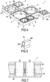
- the tubular element 6 is in the form of a ring or a ferrule of closed circular shape, inside which a sheath 10 is mounted using an assembly system 11 of all types ensuring a removable connection between the sheath 10 and the support 7.
- the assembly system 11 ensures a removable connection between the sheath 10 and the tubular element 6 to allow either the mounting of the sheath 10 on the support 7 at any chosen time by the user either after the concrete pouring operation, the removal of the sheath 10 from the wall thus formed.
- the assembly system 11 between the sheath 10 and the tubular element 6 is interlocking with a more or less tight clearance between the sheath 10 and the tubular element 6.
- the sheath 10 and the tubular element 6 have diameters to present a tight fit by hand, making it possible to engage the sheath 10 inside the tubular element 6 in order to position the support 7 at a determined fixed distance from the ends of the sheath 10.
- the assembly system 11 can also include gadroons or asperities arranged on the tubular element 6 and/or on the external surface 10a of the tube 10.
- the system assembly 11 can consist of a conical interlocking between the sheath 10 and the tubular element 6.
- the tubular element 6 is secured to the frame 13 by a perforated connecting structure 18 presenting a series of spaces 15a together defining the opening 15.
- This openwork connecting structure 18 is produced in any appropriate manner to ensure that the sheath 10 is maintained relative to the frame 13 while leaving spaces 15a of surfaces adapted to allow the passage of the concrete through the support 7. In this way, this openwork connecting structure 18 thus makes it possible to connect the frame 13 with the tubular element 6, in a punctual manner, that is to say leaving spaces 15a for the passage of concrete.
- the method according to the invention then consists of pouring the concrete inside the formwork panel(s) 2a, 2b, that is to say between the formwork panels 2a, 2b for the creation of a wall or -above the bottom formwork panel 2b for making a floor.
- this operation is carried out to ensure the passage of the concrete through the opening 15 of the faces of the frame(s) of the device 1. Taking into account the openings 15 presented by the supports 7, the device of reservation does not or only slightly affect the mechanical resistance of the wall 3 thus constituted.
- the process then consists of stripping the formwork after drying by removing the formwork panel(s) 2a, 2b.
- the process then consists of removing the sheaths 10 from the wall thus formed. Only supports 7 remain anchored in wall 3.
Landscapes
- Engineering & Computer Science (AREA)
- Architecture (AREA)
- Mechanical Engineering (AREA)
- Civil Engineering (AREA)
- Structural Engineering (AREA)
- General Engineering & Computer Science (AREA)
- Forms Removed On Construction Sites Or Auxiliary Members Thereof (AREA)
Claims (13)
- Aussparungsvorrichtung von Rohrleitungsdurchgängen beim Gießen einer Wand in einer Schalung, umfassend mindestens ein Modul (5), umfassend einen rohrförmigen Ring (6), der eine Längsachse (X) aufweist und außen von einem Verankerungsträger (7) getragen wird, der sich außen und quer zu der Achse des rohrförmigen Rings erstreckt und zwei Querflächen (8) aufweist, die entlang der Längsachse ausgerichtet sind, der Träger (7) umfassend einen Rahmen (13) mit mindestens vier Seiten (12), der stellenweise mit der Außenseite des rohrförmigen Rings (6) verbunden ist, der durch eine durchbrochene Verbindungsstruktur (18), die eine Reihe von Räumen (15a) aufweist, die zusammen eine Öffnung (15) definieren, die sich auf beiden Seiten des Trägers entlang seiner Flächen (8) öffnet, um den Durchgang des Gießmaterials zu gewährleisten, der Träger (7) umfassend Stützfüße (21), die sich in Verlängerung des Rahmens (13) von einer der Flächen (8) des Rahmens erstrecken, wobei der rohrförmige Ring (6) mit einem Zusammenbausystem (11) versehen ist, das eine lösbare Verbindung zwischen dem Träger (7) und einer Hülse (10), umfassend zwei gegenüberliegende Enden (10b), gewährleistet, wobei die Vorrichtung, umfassend die Hülse (10) und den rohrförmigen Ring (6), als Zusammenbausystem (11) mit einer inneren Oberfläche zum Einpassen der Hülse (10) versehen ist, die im Inneren des rohrförmigen Rings (6) montiert ist, um nach der Verankerung des Trägers in der Wand aus dem Träger (7) herausgezogen werden zu können, wobei sich die Hülse (10) entlang der Längsachse über eine Länge erstreckt, die mindestens gleich wie die Stärke des Trägers (7) ist, wobei sich eines der Enden in einer Ebene erstreckt, die mit der Querfläche (8) des Trägers zusammenfällt, die das Ende der Stützfüße (21) enthält, und sich deren anderes Ende in einer Ebene erstreckt, die in Bezug auf die gegenüberliegende Querfläche (8) hervorsteht.
- Aussparungsvorrichtung nach Anspruch 1, dadurch gekennzeichnet, dass das Zusammenbausystem (11) der Hülse (10) mit dem rohrförmigen Ring (6) durch konisches Einpassen oder mit Presssitz erfolgt.
- Aussparungsvorrichtung nach einem der Ansprüche 1 bis 2, dadurch gekennzeichnet, dass das Zusammenbausystem (11) der Hülse (10) im Inneren des rohrförmigen Rings (6) Unebenheiten aufweist, die auf dem rohrförmigen Ring (6) und/oder auf der äußeren Oberfläche (10a) des Rohrs (10) ausgebildet sind.
- Aussparungsvorrichtung nach einem der Ansprüche 1 bis 3, dadurch gekennzeichnet, dass die Seiten (12) des Rahmens (13) außen durchgehende ebene Auflageflächen (12a) für weitere Aussparungsmodule (5) aufweisen.
- Aussparungsvorrichtung nach einem der Ansprüche 1 bis 4, dadurch gekennzeichnet, dass der Rahmen (13) des Trägers (7) mit Zusammenbausystemen (23) für mindestens ein weiteres Aussparungsmodul versehen ist.
- Aussparungsvorrichtung nach einem der Ansprüche 1 bis 5, dadurch gekennzeichnet, dass sie mindestens zwei Aussparungsmodule (5) umfasst, die auf zwei benachbarten Seiten (12) der Rahmen aufliegen und mittels Zusammenbausystemen (23) fest miteinander verbunden sind.
- Aussparungsvorrichtung nach Anspruch 5 oder 6, dadurch gekennzeichnet, dass sie als Zusammenbausysteme (23) Klammern aufweist, die jeweils zwei benachbarte Seiten von zwei Rahmen, die zu verschiedenen Modulen gehören, einklemmen.
- Aussparungsvorrichtung nach Anspruch 7, dadurch gekennzeichnet, dass die Seiten (12) eines Rahmens (13) über mindestens einen Teil ihrer Länge eine konstante Stärke für die Montage einer Klammer (23) zum Zusammenbau eines weiteren Aussparungsmoduls besitzen.
- Aussparungsvorrichtung nach einem der Ansprüche 1 bis 8, dadurch gekennzeichnet, dass der Träger (7) mit einem Verschlussdeckel eines der Enden (10b) der Hülse (10) ausgestattet ist, der sich entlang einer Querseite des Trägers (7) erstreckt.
- Verfahren zum Bilden einer Aussparung in einer Betonwand mittels einer Vorrichtung nach einem der Ansprüche 1 bis 9, dadurch gekennzeichnet, dass es die folgenden Schritte umfasst:- Aufstellen mindestens einer Schalungsplatte (2a);- Aufstellen mindestens eines Gerüsts (30);- Positionieren der Aussparungsvorrichtung (1) nach einem der Ansprüche 1 bis 9 in Kontakt mit der Schalungsplatte;- Befestigen der Aussparungsvorrichtung (1) an dem Gerüst;- Verschließen der Enden der Hülse(n) (10) der Aussparungsvorrichtung (1);- Gießen des Betons in die Innenseite der Schalungsplatte(n) (2a, 2b) und Sicherstellen des Durchgangs des Betons durch die Öffnung (15) der Flächen des Rahmens bzw. der Rahmen (13) der Vorrichtung (1);- Ausschalen nach dem Trocknen;- Entfernen der Hülsen (10) aus der so gebildeten Wand.
- Verfahren nach Anspruch 10, dadurch gekennzeichnet, dass es vor der Positionierung der Aussparungsvorrichtung (1) gegen die Schalungsplatte (2a) aus Folgendem besteht:- Definieren einer Konfiguration für die Aussparungsvorrichtung;- Zusammenbauen der Aussparungsmodule (5) miteinander entsprechend der gewählten Konfiguration;- Ausführen einer Anzeichnung auf der Schalungsplatte zum Positionieren der Aussparungsvorrichtung.
- Verfahren nach Anspruch 10, dadurch gekennzeichnet, dass es darin besteht, das Ende der Hülse(n) (10) zu verschließen, indem auf der Schalungsplatte (2a) Verschlussdeckel der Hülsen (10) befestigt werden, und die Aussparungsvorrichtung (1) zu positionieren, sodass die Enden der Hülsen jeweils in einen Verschlussdeckel eingreifen.
- Verfahren nach Anspruch 10, dadurch gekennzeichnet, dass es darin besteht, das Ende (10b) einer Hülse zu verschließen, indem es mit einem Verschlussdeckel zusammenwirkt, der an dem Aussparungsmodul (5) befestigt ist.
Applications Claiming Priority (1)
| Application Number | Priority Date | Filing Date | Title |
|---|---|---|---|
| FR1451266A FR3017636B1 (fr) | 2014-02-18 | 2014-02-18 | Dispositif de reservation de passages de canalisations |
Publications (3)
| Publication Number | Publication Date |
|---|---|
| EP2907927A1 EP2907927A1 (de) | 2015-08-19 |
| EP2907927C0 EP2907927C0 (de) | 2024-07-03 |
| EP2907927B1 true EP2907927B1 (de) | 2024-07-03 |
Family
ID=51014408
Family Applications (1)
| Application Number | Title | Priority Date | Filing Date |
|---|---|---|---|
| EP15155279.1A Active EP2907927B1 (de) | 2014-02-18 | 2015-02-16 | Vorrichtung zur aussparung von kanalisationsdurchlässen |
Country Status (2)
| Country | Link |
|---|---|
| EP (1) | EP2907927B1 (de) |
| FR (1) | FR3017636B1 (de) |
Families Citing this family (3)
| Publication number | Priority date | Publication date | Assignee | Title |
|---|---|---|---|---|
| CN113685022A (zh) * | 2021-08-31 | 2021-11-23 | 中国第十八冶金建设有限公司 | 一种用于对吊洞模板进行支撑的装置 |
| CN114704084B (zh) * | 2022-04-14 | 2024-08-27 | 河南宇恒建筑工程有限公司 | 一种便于调节的建筑工程留洞装置 |
| CN115012656B (zh) * | 2022-06-15 | 2023-06-13 | 中建八局科技建设有限公司 | 垫石预留孔组合式卡具及其施工方法 |
Family Cites Families (8)
| Publication number | Priority date | Publication date | Assignee | Title |
|---|---|---|---|---|
| IT1248510B (it) * | 1991-06-20 | 1995-01-19 | Elcom Srl | Passaparatia componibile per quadri elettrici |
| US5230190A (en) * | 1992-10-05 | 1993-07-27 | Empak, Inc. | Joist bridge and duct support |
| FR2712330B1 (fr) | 1993-11-10 | 1998-12-24 | Michel Destouches | Plaque de coffrage perdue destinée aux réservations dans les planchers des canalisations tous fluides. |
| DE19528685C2 (de) * | 1995-08-03 | 1999-02-18 | Berndt Saurwein | Vorrichtung zur Herstellung von Installationsdurchbrüchen |
| US6450505B1 (en) * | 1998-12-18 | 2002-09-17 | Norman W. Gavin | Seal for casting in a concrete wall of a fluid distribution system container |
| US6715247B1 (en) * | 2002-09-27 | 2004-04-06 | Bowco Industries Inc. | Modular bracket for supporting passage cores for concrete structures |
| US8336833B2 (en) * | 2009-05-15 | 2012-12-25 | M.A. Industries, Inc. | Modular grid system |
| PL2511580T5 (pl) | 2011-03-21 | 2021-08-30 | Hauff-Technik Gmbh & Co. Kg | Przepust izolowany do osadzenia w elemencie ściany albo podłogi |
-
2014
- 2014-02-18 FR FR1451266A patent/FR3017636B1/fr active Active
-
2015
- 2015-02-16 EP EP15155279.1A patent/EP2907927B1/de active Active
Also Published As
| Publication number | Publication date |
|---|---|
| FR3017636B1 (fr) | 2018-05-25 |
| EP2907927A1 (de) | 2015-08-19 |
| FR3017636A1 (fr) | 2015-08-21 |
| EP2907927C0 (de) | 2024-07-03 |
Similar Documents
| Publication | Publication Date | Title |
|---|---|---|
| EP3219873B1 (de) | Verteilerkasten zum einbau von kanalisationsrohren, der zur positionierung auf einer armatur geeignet ist | |
| EP2907927A1 (de) | Vorrichtung zur Aussparung von Kanalisationsdurchlässen | |
| EP2000605A2 (de) | Vorrichtung und Zubehörteile zur Sicherstellung der Isolierung an thermischen Trennungen in Gebäudeisolierung | |
| EP0152367A1 (de) | Vorrichtung zum Herstellen von Fugen, im allgemeinen in Industriefussböden aus Beton | |
| EP2466707A1 (de) | Bodenkasten zum Einbau in eine Betonplatte oder ein technisches Parkett | |
| FR3002376A1 (fr) | Bouchon d'etancheite pour cable electrique contre les infiltrations d'air dans les batiments et procede de pose du cable electrique | |
| EP1709355B1 (de) | System zur verbindung eines kanals mit einem plattenausgang | |
| EP2739786B1 (de) | ANORDNUNG UMFASSEND EIN GLEIS, EIN DRAINAGESYSTEM UND EINEN VERSCHLUßSTOPFEN | |
| FR2941725A1 (fr) | Element d'isolation thermique pour bloc prefabrique et bloc de construction ainsi obtenu. | |
| EP0668408B1 (de) | Rinne und feststellbares Rinnenelement | |
| FR2908801A1 (fr) | Bloc de construction | |
| WO2011135235A1 (fr) | Paroi moulee avec parement prefabrique | |
| FR2891288A1 (fr) | Montant telescopique pour la realisation de parois murales et procede de montage | |
| FR3032983A1 (fr) | Dispositif de collecte des eaux de ruissellement | |
| FR3041672B1 (fr) | Coque de piscine en matiere plastique pourvue d'elements de renfort | |
| FR3001745A1 (fr) | Procede de construction d'un plancher a l'aide de predalles semi-suspendues et regle pour sa mise en œuvre | |
| FR3115308A1 (fr) | Procédé et dispositif de fixation d’un corbeau métallique de soutènement d’un mur | |
| WO2009103892A2 (fr) | Module prefabrique pour la construction d'un mur d'elevation d'une cloison | |
| FR2672337A1 (fr) | Procede pour realiser une structure a barreaux et montants, telle qu'une echelle, et structure s'y rapportant. | |
| FR3139843A1 (fr) | Boîte d’incorporation pour dalle béton | |
| FR2738581A1 (fr) | Coffrage perdu pour la realisation de parois porteuses isolantes thermiquement et/ou phonetiquement et parois ainsi obtenues | |
| FR3139845A1 (fr) | Boîte d’incorporation pour dalle béton | |
| EP2218848A1 (de) | Block für eine verlorene Schalung und Modul für den Bau einer solchen Schalung | |
| FR3047503A1 (fr) | Dispositif de fixation d'un garde-corps a un mur prefabrique et garde-corps associe | |
| FR3022271A1 (fr) | Construction mixte bois et beton |
Legal Events
| Date | Code | Title | Description |
|---|---|---|---|
| PUAI | Public reference made under article 153(3) epc to a published international application that has entered the european phase |
Free format text: ORIGINAL CODE: 0009012 |
|
| AK | Designated contracting states |
Kind code of ref document: A1 Designated state(s): AL AT BE BG CH CY CZ DE DK EE ES FI FR GB GR HR HU IE IS IT LI LT LU LV MC MK MT NL NO PL PT RO RS SE SI SK SM TR |
|
| AX | Request for extension of the european patent |
Extension state: BA ME |
|
| 17P | Request for examination filed |
Effective date: 20160211 |
|
| RBV | Designated contracting states (corrected) |
Designated state(s): AL AT BE BG CH CY CZ DE DK EE ES FI FR GB GR HR HU IE IS IT LI LT LU LV MC MK MT NL NO PL PT RO RS SE SI SK SM TR |
|
| STAA | Information on the status of an ep patent application or granted ep patent |
Free format text: STATUS: EXAMINATION IS IN PROGRESS |
|
| 17Q | First examination report despatched |
Effective date: 20170303 |
|
| P01 | Opt-out of the competence of the unified patent court (upc) registered |
Effective date: 20230502 |
|
| P02 | Opt-out of the competence of the unified patent court (upc) changed |
Effective date: 20230503 |
|
| GRAP | Despatch of communication of intention to grant a patent |
Free format text: ORIGINAL CODE: EPIDOSNIGR1 |
|
| STAA | Information on the status of an ep patent application or granted ep patent |
Free format text: STATUS: GRANT OF PATENT IS INTENDED |
|
| INTG | Intention to grant announced |
Effective date: 20240126 |
|
| GRAS | Grant fee paid |
Free format text: ORIGINAL CODE: EPIDOSNIGR3 |
|
| GRAA | (expected) grant |
Free format text: ORIGINAL CODE: 0009210 |
|
| STAA | Information on the status of an ep patent application or granted ep patent |
Free format text: STATUS: THE PATENT HAS BEEN GRANTED |
|
| AK | Designated contracting states |
Kind code of ref document: B1 Designated state(s): AL AT BE BG CH CY CZ DE DK EE ES FI FR GB GR HR HU IE IS IT LI LT LU LV MC MK MT NL NO PL PT RO RS SE SI SK SM TR |
|
| REG | Reference to a national code |
Ref country code: CH Ref legal event code: EP |
|
| REG | Reference to a national code |
Ref country code: DE Ref legal event code: R096 Ref document number: 602015089091 Country of ref document: DE |
|
| U01 | Request for unitary effect filed |
Effective date: 20240801 |
|
| U07 | Unitary effect registered |
Designated state(s): AT BE BG DE DK EE FI FR IT LT LU LV MT NL PT SE SI Effective date: 20240813 |
|
| P04 | Withdrawal of opt-out of the competence of the unified patent court (upc) registered |
Free format text: CASE NUMBER: APP_46051/2024 Effective date: 20240808 |
|
| P05 | Withdrawal of opt-out of the competence of the unified patent court (upc) changed |
Free format text: CASE NUMBER: APP_46051/2024 Effective date: 20240813 |
|
| U20 | Renewal fee for the european patent with unitary effect paid |
Year of fee payment: 11 Effective date: 20241202 |
|
| PG25 | Lapsed in a contracting state [announced via postgrant information from national office to epo] |
Ref country code: NO Free format text: LAPSE BECAUSE OF FAILURE TO SUBMIT A TRANSLATION OF THE DESCRIPTION OR TO PAY THE FEE WITHIN THE PRESCRIBED TIME-LIMIT Effective date: 20241003 |
|
| PG25 | Lapsed in a contracting state [announced via postgrant information from national office to epo] |
Ref country code: GR Free format text: LAPSE BECAUSE OF FAILURE TO SUBMIT A TRANSLATION OF THE DESCRIPTION OR TO PAY THE FEE WITHIN THE PRESCRIBED TIME-LIMIT Effective date: 20241004 Ref country code: PL Free format text: LAPSE BECAUSE OF FAILURE TO SUBMIT A TRANSLATION OF THE DESCRIPTION OR TO PAY THE FEE WITHIN THE PRESCRIBED TIME-LIMIT Effective date: 20240703 |
|
| PG25 | Lapsed in a contracting state [announced via postgrant information from national office to epo] |
Ref country code: IS Free format text: LAPSE BECAUSE OF FAILURE TO SUBMIT A TRANSLATION OF THE DESCRIPTION OR TO PAY THE FEE WITHIN THE PRESCRIBED TIME-LIMIT Effective date: 20241103 |
|
| PG25 | Lapsed in a contracting state [announced via postgrant information from national office to epo] |
Ref country code: HR Free format text: LAPSE BECAUSE OF FAILURE TO SUBMIT A TRANSLATION OF THE DESCRIPTION OR TO PAY THE FEE WITHIN THE PRESCRIBED TIME-LIMIT Effective date: 20240703 Ref country code: CZ Free format text: LAPSE BECAUSE OF FAILURE TO SUBMIT A TRANSLATION OF THE DESCRIPTION OR TO PAY THE FEE WITHIN THE PRESCRIBED TIME-LIMIT Effective date: 20240703 |
|
| PG25 | Lapsed in a contracting state [announced via postgrant information from national office to epo] |
Ref country code: RS Free format text: LAPSE BECAUSE OF FAILURE TO SUBMIT A TRANSLATION OF THE DESCRIPTION OR TO PAY THE FEE WITHIN THE PRESCRIBED TIME-LIMIT Effective date: 20241003 Ref country code: ES Free format text: LAPSE BECAUSE OF FAILURE TO SUBMIT A TRANSLATION OF THE DESCRIPTION OR TO PAY THE FEE WITHIN THE PRESCRIBED TIME-LIMIT Effective date: 20240703 |
|
| PG25 | Lapsed in a contracting state [announced via postgrant information from national office to epo] |
Ref country code: RS Free format text: LAPSE BECAUSE OF FAILURE TO SUBMIT A TRANSLATION OF THE DESCRIPTION OR TO PAY THE FEE WITHIN THE PRESCRIBED TIME-LIMIT Effective date: 20241003 Ref country code: PL Free format text: LAPSE BECAUSE OF FAILURE TO SUBMIT A TRANSLATION OF THE DESCRIPTION OR TO PAY THE FEE WITHIN THE PRESCRIBED TIME-LIMIT Effective date: 20240703 Ref country code: NO Free format text: LAPSE BECAUSE OF FAILURE TO SUBMIT A TRANSLATION OF THE DESCRIPTION OR TO PAY THE FEE WITHIN THE PRESCRIBED TIME-LIMIT Effective date: 20241003 Ref country code: IS Free format text: LAPSE BECAUSE OF FAILURE TO SUBMIT A TRANSLATION OF THE DESCRIPTION OR TO PAY THE FEE WITHIN THE PRESCRIBED TIME-LIMIT Effective date: 20241103 Ref country code: HR Free format text: LAPSE BECAUSE OF FAILURE TO SUBMIT A TRANSLATION OF THE DESCRIPTION OR TO PAY THE FEE WITHIN THE PRESCRIBED TIME-LIMIT Effective date: 20240703 Ref country code: GR Free format text: LAPSE BECAUSE OF FAILURE TO SUBMIT A TRANSLATION OF THE DESCRIPTION OR TO PAY THE FEE WITHIN THE PRESCRIBED TIME-LIMIT Effective date: 20241004 Ref country code: ES Free format text: LAPSE BECAUSE OF FAILURE TO SUBMIT A TRANSLATION OF THE DESCRIPTION OR TO PAY THE FEE WITHIN THE PRESCRIBED TIME-LIMIT Effective date: 20240703 Ref country code: CZ Free format text: LAPSE BECAUSE OF FAILURE TO SUBMIT A TRANSLATION OF THE DESCRIPTION OR TO PAY THE FEE WITHIN THE PRESCRIBED TIME-LIMIT Effective date: 20240703 |
|
| PG25 | Lapsed in a contracting state [announced via postgrant information from national office to epo] |
Ref country code: SM Free format text: LAPSE BECAUSE OF FAILURE TO SUBMIT A TRANSLATION OF THE DESCRIPTION OR TO PAY THE FEE WITHIN THE PRESCRIBED TIME-LIMIT Effective date: 20240703 |
|
| PG25 | Lapsed in a contracting state [announced via postgrant information from national office to epo] |
Ref country code: SK Free format text: LAPSE BECAUSE OF FAILURE TO SUBMIT A TRANSLATION OF THE DESCRIPTION OR TO PAY THE FEE WITHIN THE PRESCRIBED TIME-LIMIT Effective date: 20240703 |
|
| PLBE | No opposition filed within time limit |
Free format text: ORIGINAL CODE: 0009261 |
|
| STAA | Information on the status of an ep patent application or granted ep patent |
Free format text: STATUS: NO OPPOSITION FILED WITHIN TIME LIMIT |
|
| 26N | No opposition filed |
Effective date: 20250404 |
|
| PG25 | Lapsed in a contracting state [announced via postgrant information from national office to epo] |
Ref country code: MC Free format text: LAPSE BECAUSE OF FAILURE TO SUBMIT A TRANSLATION OF THE DESCRIPTION OR TO PAY THE FEE WITHIN THE PRESCRIBED TIME-LIMIT Effective date: 20240703 |
|
| REG | Reference to a national code |
Ref country code: CH Ref legal event code: PL |
|
| PG25 | Lapsed in a contracting state [announced via postgrant information from national office to epo] |
Ref country code: CH Free format text: LAPSE BECAUSE OF NON-PAYMENT OF DUE FEES Effective date: 20250228 |
|
| U20 | Renewal fee for the european patent with unitary effect paid |
Year of fee payment: 12 Effective date: 20251201 |
|
| PG25 | Lapsed in a contracting state [announced via postgrant information from national office to epo] |
Ref country code: IE Free format text: LAPSE BECAUSE OF NON-PAYMENT OF DUE FEES Effective date: 20250216 |
|
| PGFP | Annual fee paid to national office [announced via postgrant information from national office to epo] |
Ref country code: GB Payment date: 20260219 Year of fee payment: 12 |
|
| PG25 | Lapsed in a contracting state [announced via postgrant information from national office to epo] |
Ref country code: RO Free format text: LAPSE BECAUSE OF FAILURE TO SUBMIT A TRANSLATION OF THE DESCRIPTION OR TO PAY THE FEE WITHIN THE PRESCRIBED TIME-LIMIT Effective date: 20240703 |