EP1709355B1 - System zur verbindung eines kanals mit einem plattenausgang - Google Patents
System zur verbindung eines kanals mit einem plattenausgang Download PDFInfo
- Publication number
- EP1709355B1 EP1709355B1 EP05717494A EP05717494A EP1709355B1 EP 1709355 B1 EP1709355 B1 EP 1709355B1 EP 05717494 A EP05717494 A EP 05717494A EP 05717494 A EP05717494 A EP 05717494A EP 1709355 B1 EP1709355 B1 EP 1709355B1
- Authority
- EP
- European Patent Office
- Prior art keywords
- slab
- outlet
- sheath
- positioning device
- positioning
- Prior art date
- Legal status (The legal status is an assumption and is not a legal conclusion. Google has not performed a legal analysis and makes no representation as to the accuracy of the status listed.)
- Expired - Lifetime
Links
- 230000008878 coupling Effects 0.000 title 1
- 238000010168 coupling process Methods 0.000 title 1
- 238000005859 coupling reaction Methods 0.000 title 1
- 238000009416 shuttering Methods 0.000 claims description 5
- 230000003247 decreasing effect Effects 0.000 claims description 4
- RYGMFSIKBFXOCR-UHFFFAOYSA-N Copper Chemical compound [Cu] RYGMFSIKBFXOCR-UHFFFAOYSA-N 0.000 description 4
- 229910052802 copper Inorganic materials 0.000 description 4
- 239000010949 copper Substances 0.000 description 4
- 238000009415 formwork Methods 0.000 description 4
- 239000004698 Polyethylene Substances 0.000 description 3
- 239000004793 Polystyrene Substances 0.000 description 3
- 239000000463 material Substances 0.000 description 3
- 238000000034 method Methods 0.000 description 3
- 239000004570 mortar (masonry) Substances 0.000 description 3
- -1 polyethylene Polymers 0.000 description 3
- 229920000573 polyethylene Polymers 0.000 description 3
- 229920002223 polystyrene Polymers 0.000 description 3
- XEEYBQQBJWHFJM-UHFFFAOYSA-N Iron Chemical compound [Fe] XEEYBQQBJWHFJM-UHFFFAOYSA-N 0.000 description 2
- 238000005266 casting Methods 0.000 description 2
- 239000004033 plastic Substances 0.000 description 2
- 229920003023 plastic Polymers 0.000 description 2
- XLYOFNOQVPJJNP-UHFFFAOYSA-N water Substances O XLYOFNOQVPJJNP-UHFFFAOYSA-N 0.000 description 2
- 238000003466 welding Methods 0.000 description 2
- 230000006978 adaptation Effects 0.000 description 1
- 238000004026 adhesive bonding Methods 0.000 description 1
- 239000004568 cement Substances 0.000 description 1
- 230000000295 complement effect Effects 0.000 description 1
- 230000005611 electricity Effects 0.000 description 1
- 229940082150 encore Drugs 0.000 description 1
- 235000021183 entrée Nutrition 0.000 description 1
- 239000013529 heat transfer fluid Substances 0.000 description 1
- 238000002513 implantation Methods 0.000 description 1
- 238000009434 installation Methods 0.000 description 1
- 229910052742 iron Inorganic materials 0.000 description 1
- 238000004519 manufacturing process Methods 0.000 description 1
- 238000005192 partition Methods 0.000 description 1
- 229920002635 polyurethane Polymers 0.000 description 1
- 239000004814 polyurethane Substances 0.000 description 1
- 238000011084 recovery Methods 0.000 description 1
- 230000003014 reinforcing effect Effects 0.000 description 1
- 238000000926 separation method Methods 0.000 description 1
- 229920002994 synthetic fiber Polymers 0.000 description 1
- 239000002699 waste material Substances 0.000 description 1
Images




Classifications
-
- E—FIXED CONSTRUCTIONS
- E04—BUILDING
- E04G—SCAFFOLDING; FORMS; SHUTTERING; BUILDING IMPLEMENTS OR AIDS, OR THEIR USE; HANDLING BUILDING MATERIALS ON THE SITE; REPAIRING, BREAKING-UP OR OTHER WORK ON EXISTING BUILDINGS
- E04G15/00—Forms or shutterings for making openings, cavities, slits, or channels
- E04G15/06—Forms or shutterings for making openings, cavities, slits, or channels for cavities or channels in walls of floors, e.g. for making chimneys
- E04G15/061—Non-reusable forms
-
- F—MECHANICAL ENGINEERING; LIGHTING; HEATING; WEAPONS; BLASTING
- F16—ENGINEERING ELEMENTS AND UNITS; GENERAL MEASURES FOR PRODUCING AND MAINTAINING EFFECTIVE FUNCTIONING OF MACHINES OR INSTALLATIONS; THERMAL INSULATION IN GENERAL
- F16L—PIPES; JOINTS OR FITTINGS FOR PIPES; SUPPORTS FOR PIPES, CABLES OR PROTECTIVE TUBING; MEANS FOR THERMAL INSULATION IN GENERAL
- F16L3/00—Supports for pipes, cables or protective tubing, e.g. hangers, holders, clamps, cleats, clips, brackets
- F16L3/08—Supports for pipes, cables or protective tubing, e.g. hangers, holders, clamps, cleats, clips, brackets substantially surrounding the pipe, cable or protective tubing
- F16L3/12—Supports for pipes, cables or protective tubing, e.g. hangers, holders, clamps, cleats, clips, brackets substantially surrounding the pipe, cable or protective tubing comprising a member substantially surrounding the pipe, cable or protective tubing
- F16L3/1226—Supports for pipes, cables or protective tubing, e.g. hangers, holders, clamps, cleats, clips, brackets substantially surrounding the pipe, cable or protective tubing comprising a member substantially surrounding the pipe, cable or protective tubing elongated supports, e.g. to support a curved pipe
Definitions
- the present invention relates to the field of devices and processes for the realization of new works, such as living rooms, with slabs of water supply conduits, electricity or for all other applications.
- the present invention relates more particularly to devices and installations for connecting a sheath, such as a flexible or semi-rigid pipe or consisting of a pipe, at the exit of a slab.
- the present invention intends to overcome the disadvantages of the prior art by proposing a simple system comprising two elements, one consisting of the connecting tube and the other consisting of an element for the precise placement of said connecting tube.
- This system once the tube and the placement element set up and fixed to one another, allows to pour the concrete directly without the need for a reservation to finish the work, without requiring the implementation place boxes of cardboard or polystyrene which must then be removed.
- the system according to the invention once set up, pouring concrete is done directly and completely without interruption as in the prior art to make a reservation.
- the present invention relates to a system for connecting a sheath, or the like, to the exit of a slab, comprising a slab exit device comprising at least one duct which is fixed at one of its ends.
- a slab exit device comprising at least one duct which is fixed at one of its ends.
- the sheath characterized in that it comprises a placement device, on which is fixed the slab exit device, comprising a means positioning device for positioning said slab exit device with respect to one or more reference (s).
- references refers to any fixed element in the place where the duct connection is placed and which can be used to correctly position the connection, that is to say the connection device.
- exit slabs such as for example walls or partitions.
- the placement device also comprises at least one base for raising it and at least one orifice.
- this device may have a plurality of orifices. These orifices being mainly intended to allow the flow of concrete, or the like, all around the placement device.
- the placement device may comprise an upper protuberance engaging with at least one lower protrusion present on the slab exit device.
- the positioning means will consist of at least two straight lines of axis.
- the positioning means will consist of three straight lines of axis.
- the placement device is fixed on a formwork board.
- the slab exit device can slide on said placement device.
- the slab exit device will be fixed to the placement device by gluing and / or clipping.
- the sleeve end will have on its inner face wings, or protuberances, and / or a diameter decreasing from its free periphery. This case will be particularly considered when the sheath of the slab will have a fluted end.
- these protuberances may consist of substantially elastic elements engaging in the grooves to lock back the end of the sheath and ensure the tightness of the junction.
- the inner face of the sheath end is smooth and / or has a decreasing diameter from its free periphery.
- the placement device may comprise at least one attachment means for fixing, or to be fixed to, another placement device.
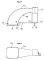
- the slab outlet device 1 is in the form of an L since it is intended to connect a sheath 2, or the like, located slightly below the ground to a pipe located above the level of the ground level. This pipe may be a water supply pipe for a valve or a radiator, not shown in the accompanying figures.
- the slab outlet device 1 is a synthetic material, generally made of rigid plastic such as polyurethane.
- the slab outlet device 1 thus comprises an inlet 3 located at one of its ends, the lower end, for the connection to the sheath 2.
- the device 1 also comprises an outlet 4 located at the other end, the upper end, intended for connection with the external conduit, not shown in the accompanying figures.
- This device 1 defines, between the inlet 3 and the outlet 4, a curved conduit in which a channel 10 can pass, as can be seen on the figure 3 .
- the inlet 3 has a circular section of diameter adapted to receive the sheath 2.
- the outlet 4 has an oblong section whose width corresponds to the diameter of the inlet.
- the duct 5 thus flares out between the inlet 3 and the outlet 4.
- the length of the oblong section of the outlet is chosen so that the radius of curvature of the duct is adapted to the passage of the pipe 10.
- the duct 5 shown allows the passage of polyethylene pipes of diameters (inside-outside) 10-12 mm, 13-16 mm and 16-20 mm.
- the radius of curvature of the duct 5 of the slab outlet device 1 makes it possible to obtain the passage of the pipe 10 without intervention or the need for other tools. It can be provided that the slab outlet device 1 has lateral recesses for the passage of concrete, in order to obtain good cohesion of the assembly.
- the slab exit device 1 comprises two lower protuberances forming a dovetail sliding guide for engaging the rail of a placement device for connecting these two devices with a sliding degree of freedom.
- a clamping screw (not shown) intervening between these two devices makes it possible to completely immobilize these devices with respect to one another.
- the slab outlet device 1 comprises a plug 9 which will be positioned on the outlet orifice 4 to prevent any passage of concrete during casting, or filling, reservation. After pouring, this plug 9 will be removed to make the connection to the external duct of the pipe 10, or the pipe or directly of the outlet orifice 4.
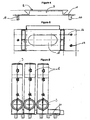
- the placement device 8 consists of a plate 11 having a base 10 to raise it when it is placed on the shuttering board 16, not shown in the accompanying figures.
- This base 10 here consists of simple studs or support rails, made of the same material as the plate 11 or in a different material.
- this base is molded with the plate 11.
- This elevation of the plate 11 of the placement device 8 allows the concrete, or the like, to flow better underneath to allow a good finish under slab after pouring.
- the upper protuberance 7 in the form of a dovetail already described above is formed on the upper part of the plate 11.
- a central hole 12 in the form of an oblong hole allows the concrete, or the like, to flow in order to complete the assembly.
- the base 10, namely, in this case the pads has longitudinal openings 13 for receiving fastening nails, allowing the attachment of the placing device 8 on a formwork board 16.
- the upper protuberance 7 comprises a mortise and tenon rail which serve as a fastening system for securing the placement devices 8 to each other.
- This rail allows the assembly of several placement devices 8 together, by introducing the tenon into the mortise of the next placing device 8.
- the placement device 8 comprises in the example chosen to illustrate the invention two axis lines which form the positioning means 14 of the slab outlet device 1, by sliding on the rail 7, but above all the placement device 8 itself. These lines 14, whose minimum number is two, allow the operator to correctly place, first of all the placement device 8 on the shuttering board, then the slab outlet device 1, by sliding, on the placement device 8. Once the device 8 is correctly placed on the shuttering board, it is nailed by means of nails arranged in the orifices 13. Once the slab release device is correctly placed by sliding, it is immobilized by means of the clamping screw (not shown) which intervenes between it and the placement device 8.
- the center lines 14 are here etched directly on the upper face of the placing device 8, but it will of course be possible to provide that these lines 14 are reported on said surface by printing. In the same manner, all types of means capable of allowing the placement of the placement device 8 to be correctly positioned may be envisaged, possibly without requiring the taking into account of fixed references present on the site of the work.
- the inlet 3 of the slab outlet device 1 is connected to the free end of a sheath 2.
- a lip or wing, flexible 15 is formed on the inner wall of the inlet 3. This lip is adapted to be housed in a hollow of a sheath 2 so as to ensure a good connection and a perfect seal.
- tips examples of which are represented on the Figures 10 to 13
- Each of these endpieces comprises an end 300 adapted to be fitted into the inlet 3.
- This end 300 comprises a circumferential groove 301 adapted to receive the lip 15.
- One of these endpieces, shown in FIG. figure 13 allows to connect two ducts to the slab entrance.
- a riser 400 shown on the figure 14 comprises an end 401 adapted to be fitted into the outlet 4 of the device 1 in order to enhance the latter.
- the plug 9 is removed and the pipe 10, or a pipe, is introduced through the outlet orifice 4.
- the system according to the invention makes it possible, after the casting of the concrete, to proceed and any time the interchangeability of the pipe 10, or pipe, polyethylene without recourse to the slab of the slab.
- the flared shape of a duct makes it possible to bring out two pipes 10, or pipes, of the same duct 5 and to obtain a separation at the outlet of at least 50 millimeters.
- the curved conduit 10 of the slab outlet device 1 in the case of copper pipes and because of the impossibility of passing them afterwards, the part of the external conduit to the end of the work, that is to say after pouring concrete, mortar or the like, will be made in half-shell, so that after the passage of the pipe 10 of copper, we will clip the complementary part of the half-shell.
- the duct 5 will be intersected, in its upper part, for example 4 centimeters less than the thickness of the floor to receive a conical plug on the outlet port 4, so as to extract the concrete.
- the plug 9 will include an inner cavity so as to allow the passage of the pipe 10 inside the conduit 5. This technique allows to resume the copper pipe 10 by welding at the slab and not full slab.
- a slab exit device 101 comprises an inlet 103 which is above the slab, its outlet 104 being below the slab.
- the outlet 104 towards which the conduit 105 of the slab exit device 101 is flared, is at a placement device 108 adapted to be fixed on the formwork board at the bottom of the reservation.
- the placement device 108 comprises two rails 107 and 117 with which cooperate two guides 116 and 106 which are respectively at the level of the outlet 104 and in line with the inlet 103.
- a base 110 is provided under the device placement 108, at the level of the rail 107. This base comprises at least one orifice 112 allowing the passage of a fastening nail to the board of formwork. At least one other orifice 111 is formed next to the outlet 104.
- a placement device 508 is constituted by a rail fixed to the shuttering board, for example by means of nails through holes 513 provided for this purpose.
- the slab release device 501 comprises a slider 502 adapted to engage the rail 508.
- the final attachment may, for example, be made by means of a clamping screw (not shown).
- the fastening of the placement device is carried out, for fixing in the polystyrene, by means of a large-pitch screw such as the screw 600 shown in FIG. figure 15 . It can also be achieved by means of a concrete iron 700 such as that shown in FIG. figure 16 .
Landscapes
- Engineering & Computer Science (AREA)
- Architecture (AREA)
- Mechanical Engineering (AREA)
- General Engineering & Computer Science (AREA)
- Civil Engineering (AREA)
- Structural Engineering (AREA)
- Forms Removed On Construction Sites Or Auxiliary Members Thereof (AREA)
- Supports For Pipes And Cables (AREA)
- Mechanical Coupling Of Light Guides (AREA)
- Paper (AREA)
- Diaphragms For Electromechanical Transducers (AREA)
- Bidet-Like Cleaning Device And Other Flush Toilet Accessories (AREA)
- Transceivers (AREA)
- Jigs For Machine Tools (AREA)
- Duct Arrangements (AREA)
Claims (16)
- System für den Anschluss eines Leitungskanals (2) oder analog am Austritt einer Bodenplatte, das folgende Teile umfasst:- eine Vorrichtung zum Austritt aus der Bodenplatte (1; 101; 501) mit mindestens einem gekrümmten Leitungsrohr in L-Form (5; 105), das ein oberes Ende (4) und ein ein Hüllrohr für den Anschluss an den oben besagten Leitungskanal (2) bildendes unteres Ende (3) umfasst;- eine Positionierungsvorrichtung (8; 108; 508), auf der die Vorrichtung zum Austritt aus der Bodenplatte (1) befestigt wird, die ein Positionierungsmittel (14) für das Positionieren der besagten Vorrichtung zum Austritt aus der Bodenplatte (1) im Verhältnis zu einem oder mehreren fixen Referenzelementen umfasst;Wobei das besagte System dadurch gekennzeichnet ist, dass die Positionierungsvorrichtung (8; 108; 508) zumindest einen Sockel (10) umfasst, der dazu bestimmt ist, sie anzuheben, und eine zentrale Öffnung (12) für das Gießen des Betons oder eines analogen Materials.
- System nach Anspruch 1, dadurch gekennzeichnet, dass die Positionierungsvorrichtung (8; 108; 508) eine obere Protuberanz (7; 107; 117) umfasst, die in zumindest eine untere Protuberanz (6; 106; 116) eingreift, die auf der Vorrichtung zum Austritt aus der Bodenplatte (1; 101; 501) vorhanden ist.
- System nach Anspruch 1 oder 2, dadurch gekennzeichnet, dass das Positionierungsmittel (14) aus zumindest zwei geradlinigen Strichen besteht.
- System nach Anspruch 3, dadurch gekennzeichnet, dass das Positionierungsmittel (14) aus drei geradlinigen Strichen besteht.
- System nach einem beliebigen der vorstehenden Ansprüche, dadurch gekennzeichnet, dass die Positionierungsvorrichtung (8; 108; 508) auf einem Schalbrett fixierbar ist.
- System nach einem beliebigen der vorstehenden Ansprüche, dadurch gekennzeichnet, dass die Vorrichtung zum Austritt aus der Bodenplatte (1; 101; 501) auf der Positionierungsvorrichtung (8; 108; 508) gleiten kann.
- System nach einem beliebigen der vorstehenden Ansprüche, dadurch gekennzeichnet, dass die Vorrichtung zum Austritt aus der Bodenplatte (1; 101; 501) auf der Positionierungsvorrichtung (8; 108; 508) durch Verankerung befestigt ist.
- System nach einem beliebigen der vorstehenden Ansprüche, dadurch gekennzeichnet, dass das Ende (3), das ein Hüllrohr bildet, auf seiner Innenfläche Flügel (15) und/oder einen sich ab seiner freien Peripherie verjüngenden Durchmesser aufweist.
- System nach einem beliebigen der vorstehenden Ansprüche 1 bis 9, dadurch gekennzeichnet, dass die Innenfläche des ein Hüllrohr bildenden Endes (3) glatt ist und/oder einen sich ab seiner freien Peripherie verjüngenden Durchmesser aufweist.
- System nach einem beliebigen der vorstehenden Ansprüche, dadurch gekennzeichnet, dass die Positionierungsvorrichtung (8; 108; 508) zumindest ein Mittel zur Fixierung aufweist, mit dem es an einer anderen Positionierungsvorrichtung/mit dem eine andere Positionierungsvorrichtung fixiert werden kann.
- System nach einem beliebigen der vorstehenden Ansprüche, dadurch gekennzeichnet, dass ein Ansatzstück (300) abnehmbar am ein Hüllrohr bildenden Ende (3) angeschlossen ist.
- System nach einem beliebigen der vorstehenden Ansprüche, dadurch gekennzeichnet, dass das obere Ausgangsende (4; 104; 204) einen Querschnitt hat, dessen mindestens eine Abmessung grösser als der Querschnitt des besagten Endes (3) ist, das ein Hüllrohr bildet.
- System nach Anspruch 12, dadurch gekennzeichnet, dass das besagte Ausgangsende (204) einen Querschnitt mit mindestens zwei Abmessungen grösser als diejenigen des Querschnitts des besagten Endes (3) hat, das ein Hüllrohr bildet.
- System nach einem beliebigen der vorstehenden Ansprüche, dadurch gekennzeichnet, dass die besagte Positionierungsvorrichtung (508) eine Schiene ist.
- System nach einem beliebigen der vorstehenden Ansprüche, dadurch gekennzeichnet, dass ein Ständer (400) abnehmbar an das obere Ausgangsende (4; 104; 204) angeschlossen ist.
- System nach einem beliebigen der vorstehenden Ansprüche 1 bis 15, dadurch gekennzeichnet, dass das Leitungsrohr (5; 105) einen kreisförmigen Eintrittsquerschnitt (3) mit einem Durchmesser aufweist, der geeignet ist, den Leitungskanal (2) aufzunehmen, und einen länglichen Ausgangsquerschnitt (4), dessen Breite dem Durchmesser des Eintrittsquerschnitts (3) entspricht.
Applications Claiming Priority (2)
| Application Number | Priority Date | Filing Date | Title |
|---|---|---|---|
| FR0400703A FR2865489B1 (fr) | 2004-01-26 | 2004-01-26 | Systeme pour le raccordement d'une gaine a la sortie d'une dalle |
| PCT/FR2005/000170 WO2005080846A1 (fr) | 2004-01-26 | 2005-01-26 | Systeme pour le raccordement d’une gaine a la sortie d’une dalle |
Publications (2)
| Publication Number | Publication Date |
|---|---|
| EP1709355A1 EP1709355A1 (de) | 2006-10-11 |
| EP1709355B1 true EP1709355B1 (de) | 2011-03-16 |
Family
ID=34717413
Family Applications (1)
| Application Number | Title | Priority Date | Filing Date |
|---|---|---|---|
| EP05717494A Expired - Lifetime EP1709355B1 (de) | 2004-01-26 | 2005-01-26 | System zur verbindung eines kanals mit einem plattenausgang |
Country Status (8)
| Country | Link |
|---|---|
| EP (1) | EP1709355B1 (de) |
| CN (1) | CN101065606A (de) |
| AT (1) | ATE502240T1 (de) |
| DE (1) | DE602005026911D1 (de) |
| ES (1) | ES2364809T3 (de) |
| FR (1) | FR2865489B1 (de) |
| RU (1) | RU2376427C2 (de) |
| WO (1) | WO2005080846A1 (de) |
Families Citing this family (6)
| Publication number | Priority date | Publication date | Assignee | Title |
|---|---|---|---|---|
| GB2426310A (en) * | 2005-05-17 | 2006-11-22 | Tony Heaphy | Concrete pump pipe stabilisation system |
| EP2032777A2 (de) * | 2006-06-23 | 2009-03-11 | Philippe Gérard Blot | Zubehörsatz für einen in eine betonplatte eingebetteten und zur installation von abflussleitungen vorgesehenen kasten |
| GB0702100D0 (en) * | 2007-02-03 | 2007-03-14 | Protube Ltd | An Assembly for Terminating a Flexible Water Pipe |
| EP2194212B1 (de) | 2008-12-05 | 2012-02-15 | Geberit International AG | Schalungskasten |
| FR3088098A1 (fr) | 2018-11-02 | 2020-05-08 | Smart Cast | Dispositif de raccordement de deux gaines incorporees dans le beton permettant d'assurer la continuite d'une conduite semi-rigide entre deux elements en beton, l'un etznt vertical et formant un mur, l'autre etant horizontal et formant un plancher. |
| US11962134B2 (en) | 2021-12-08 | 2024-04-16 | Erico International Corporation | In-deck conduit for concrete decks |
Family Cites Families (8)
| Publication number | Priority date | Publication date | Assignee | Title |
|---|---|---|---|---|
| CH586865A5 (en) * | 1975-06-06 | 1977-04-15 | Etasa Ag | Pipe mounting with U:shaped clips - securable to common bar by key hole slot engageable with pins on bar |
| JPH0137270Y2 (de) * | 1985-05-22 | 1989-11-10 | ||
| DE8615470U1 (de) * | 1986-06-07 | 1986-07-24 | Hewing GmbH & Co, 4434 Ochtrup | Rohrführungsbogen |
| DE8632276U1 (de) * | 1986-12-02 | 1987-02-12 | Dockweiler, Josef, 7794 Wald | Zentrifugalpumpe |
| DE8632274U1 (de) * | 1986-12-02 | 1987-02-26 | Cronatherm GmbH, 5206 Neunkirchen-Seelscheid | Rohrführungsbogen mit Montageplatte |
| DE3740487A1 (de) * | 1987-11-29 | 1989-06-08 | Thyssen Polymer Gmbh | Vorrichtung zur umlenkung von leitungen |
| JPH1061876A (ja) * | 1996-08-22 | 1998-03-06 | Jgc Corp | 配管の断熱支持装置 |
| FR2800838B1 (fr) | 1999-11-05 | 2001-12-14 | Alphacan Sa | Dispositif de raccordement d'une gaine a la sortie d'une dalle, et installation comportant un tel dispositif |
-
2004
- 2004-01-26 FR FR0400703A patent/FR2865489B1/fr not_active Expired - Lifetime
-
2005
- 2005-01-26 WO PCT/FR2005/000170 patent/WO2005080846A1/fr not_active Ceased
- 2005-01-26 EP EP05717494A patent/EP1709355B1/de not_active Expired - Lifetime
- 2005-01-26 RU RU2006130555/03A patent/RU2376427C2/ru not_active IP Right Cessation
- 2005-01-26 ES ES05717494T patent/ES2364809T3/es not_active Expired - Lifetime
- 2005-01-26 AT AT05717494T patent/ATE502240T1/de not_active IP Right Cessation
- 2005-01-26 DE DE602005026911T patent/DE602005026911D1/de not_active Expired - Lifetime
- 2005-01-26 CN CNA2005800031776A patent/CN101065606A/zh active Pending
Also Published As
| Publication number | Publication date |
|---|---|
| CN101065606A (zh) | 2007-10-31 |
| EP1709355A1 (de) | 2006-10-11 |
| WO2005080846A8 (fr) | 2006-08-24 |
| DE602005026911D1 (de) | 2011-04-28 |
| ES2364809T3 (es) | 2011-09-14 |
| ATE502240T1 (de) | 2011-04-15 |
| FR2865489A1 (fr) | 2005-07-29 |
| FR2865489B1 (fr) | 2008-01-25 |
| RU2376427C2 (ru) | 2009-12-20 |
| WO2005080846A1 (fr) | 2005-09-01 |
| RU2006130555A (ru) | 2008-03-10 |
Similar Documents
| Publication | Publication Date | Title |
|---|---|---|
| EP2771604B1 (de) | Trägervorrichtung zum verlegen von kabeln entlang untergetauchten pipeline-rohren | |
| FR2930904A1 (fr) | Assemblage de raccord rapide et outil de degagement | |
| EP1709355B1 (de) | System zur verbindung eines kanals mit einem plattenausgang | |
| FR3074205A1 (fr) | Banche, ensemble de banches et procede d'assemblage | |
| EP2907927B1 (de) | Vorrichtung zur aussparung von kanalisationsdurchlässen | |
| EP3078784B1 (de) | Mauer mit integrierter schalung mit einem entfernbaren aufnahmemittel eines anschlussmittels an ein fördergerät | |
| WO1997040233A1 (fr) | Paroi moulee a armature continue, procede de realisation d'une telle paroi et coffrage pour realiser cette paroi | |
| FR2974587A1 (fr) | Procede d'incorporation dans une dalle beton, de canalisations d'une installation de circulation d'un fluide et materiel pour sa mise en oeuvre | |
| FR2602568A1 (fr) | Dispositif de guidage et de protection pour la pose de canalisations | |
| EP3477007B1 (de) | Montageverfahren eines befestigungskits eines hahns an einer trennwand, insbesondere einer trennwand aus gipskartonplatten, und ein solches befestigungskit | |
| EP1750047A1 (de) | Befestigungselement zum Verlegen von Rohren, Kabeln, Kanalisierungen und anderen Leitungen | |
| FR2893058A1 (fr) | Dispositif pour faciliter le coffrage rapide et le montage de murs, dalles, planchers et similaires | |
| EP3945649B1 (de) | Zange zum halten von elektrischen kabeln | |
| FR2615267A1 (fr) | Outil destine a l'emboitement de canalisations | |
| CH666927A5 (en) | Concrete shuttering for underground pipe inspection pit - incorporates pleated and flexible U=shaped walls with reinforcing panels | |
| FR2721092A1 (fr) | Dispositif d'assemblage en ligne de deux éléments structuraux tubulaires. | |
| CA2246046A1 (fr) | Adaptateur pour le raccordement etanche et autobloquant de tuyaux | |
| FR3138460A1 (fr) | Boite de reservation pourvue d’une partie aimantee | |
| FR2963078A1 (fr) | Tube destine a recevoir une tubulure telle qu'un connecteur | |
| FR2663398A1 (fr) | Support de maintien pour gaines annelees de protection de canalisations de transport d'energie. | |
| EP0090755A2 (de) | Zellförmiges Wandelement aus bewehrtem Beton und Gerät zur Herstellung | |
| FR2810703A1 (fr) | Coquille de securite pour ecrou et procede de controle d'etancheite d'une conduite portant un ecrou | |
| BE343094A (de) | ||
| WO2007096413A1 (fr) | Boite collectrice metallique, echangeur de chaleur comportant une telle boite collectrice et procede de fabrication d'une telle boite collectrice | |
| WO2007003829A2 (fr) | Repartiteur d'admission d'air pour un moteur a combustion interne |
Legal Events
| Date | Code | Title | Description |
|---|---|---|---|
| PUAI | Public reference made under article 153(3) epc to a published international application that has entered the european phase |
Free format text: ORIGINAL CODE: 0009012 |
|
| 17P | Request for examination filed |
Effective date: 20060712 |
|
| AK | Designated contracting states |
Kind code of ref document: A1 Designated state(s): AT BE BG CH CY CZ DE DK EE ES FI FR GB GR HU IE IS IT LI LT LU MC NL PL PT RO SE SI SK TR |
|
| DAX | Request for extension of the european patent (deleted) | ||
| 17Q | First examination report despatched |
Effective date: 20070510 |
|
| GRAP | Despatch of communication of intention to grant a patent |
Free format text: ORIGINAL CODE: EPIDOSNIGR1 |
|
| GRAS | Grant fee paid |
Free format text: ORIGINAL CODE: EPIDOSNIGR3 |
|
| GRAA | (expected) grant |
Free format text: ORIGINAL CODE: 0009210 |
|
| AK | Designated contracting states |
Kind code of ref document: B1 Designated state(s): AT BE BG CH CY CZ DE DK EE ES FI FR GB GR HU IE IS IT LI LT LU MC NL PL PT RO SE SI SK TR |
|
| REG | Reference to a national code |
Ref country code: GB Ref legal event code: FG4D Free format text: NOT ENGLISH |
|
| REG | Reference to a national code |
Ref country code: CH Ref legal event code: EP |
|
| REG | Reference to a national code |
Ref country code: IE Ref legal event code: FG4D |
|
| REF | Corresponds to: |
Ref document number: 602005026911 Country of ref document: DE Date of ref document: 20110428 Kind code of ref document: P |
|
| REG | Reference to a national code |
Ref country code: DE Ref legal event code: R096 Ref document number: 602005026911 Country of ref document: DE Effective date: 20110428 |
|
| REG | Reference to a national code |
Ref country code: NL Ref legal event code: VDEP Effective date: 20110316 |
|
| PG25 | Lapsed in a contracting state [announced via postgrant information from national office to epo] |
Ref country code: LT Free format text: LAPSE BECAUSE OF FAILURE TO SUBMIT A TRANSLATION OF THE DESCRIPTION OR TO PAY THE FEE WITHIN THE PRESCRIBED TIME-LIMIT Effective date: 20110316 Ref country code: GR Free format text: LAPSE BECAUSE OF FAILURE TO SUBMIT A TRANSLATION OF THE DESCRIPTION OR TO PAY THE FEE WITHIN THE PRESCRIBED TIME-LIMIT Effective date: 20110617 Ref country code: SE Free format text: LAPSE BECAUSE OF FAILURE TO SUBMIT A TRANSLATION OF THE DESCRIPTION OR TO PAY THE FEE WITHIN THE PRESCRIBED TIME-LIMIT Effective date: 20110316 |
|
| REG | Reference to a national code |
Ref country code: CH Ref legal event code: NV Representative=s name: NOVAGRAAF SWITZERLAND S.A. |
|
| LTIE | Lt: invalidation of european patent or patent extension |
Effective date: 20110316 |
|
| PG25 | Lapsed in a contracting state [announced via postgrant information from national office to epo] |
Ref country code: AT Free format text: LAPSE BECAUSE OF FAILURE TO SUBMIT A TRANSLATION OF THE DESCRIPTION OR TO PAY THE FEE WITHIN THE PRESCRIBED TIME-LIMIT Effective date: 20110316 Ref country code: FI Free format text: LAPSE BECAUSE OF FAILURE TO SUBMIT A TRANSLATION OF THE DESCRIPTION OR TO PAY THE FEE WITHIN THE PRESCRIBED TIME-LIMIT Effective date: 20110316 Ref country code: BG Free format text: LAPSE BECAUSE OF FAILURE TO SUBMIT A TRANSLATION OF THE DESCRIPTION OR TO PAY THE FEE WITHIN THE PRESCRIBED TIME-LIMIT Effective date: 20110616 Ref country code: CY Free format text: LAPSE BECAUSE OF FAILURE TO SUBMIT A TRANSLATION OF THE DESCRIPTION OR TO PAY THE FEE WITHIN THE PRESCRIBED TIME-LIMIT Effective date: 20110316 Ref country code: SI Free format text: LAPSE BECAUSE OF FAILURE TO SUBMIT A TRANSLATION OF THE DESCRIPTION OR TO PAY THE FEE WITHIN THE PRESCRIBED TIME-LIMIT Effective date: 20110316 |
|
| REG | Reference to a national code |
Ref country code: ES Ref legal event code: FG2A Ref document number: 2364809 Country of ref document: ES Kind code of ref document: T3 Effective date: 20110914 |
|
| REG | Reference to a national code |
Ref country code: IE Ref legal event code: FD4D |
|
| PG25 | Lapsed in a contracting state [announced via postgrant information from national office to epo] |
Ref country code: PT Free format text: LAPSE BECAUSE OF FAILURE TO SUBMIT A TRANSLATION OF THE DESCRIPTION OR TO PAY THE FEE WITHIN THE PRESCRIBED TIME-LIMIT Effective date: 20110718 Ref country code: IE Free format text: LAPSE BECAUSE OF FAILURE TO SUBMIT A TRANSLATION OF THE DESCRIPTION OR TO PAY THE FEE WITHIN THE PRESCRIBED TIME-LIMIT Effective date: 20110316 Ref country code: EE Free format text: LAPSE BECAUSE OF FAILURE TO SUBMIT A TRANSLATION OF THE DESCRIPTION OR TO PAY THE FEE WITHIN THE PRESCRIBED TIME-LIMIT Effective date: 20110316 |
|
| PG25 | Lapsed in a contracting state [announced via postgrant information from national office to epo] |
Ref country code: SK Free format text: LAPSE BECAUSE OF FAILURE TO SUBMIT A TRANSLATION OF THE DESCRIPTION OR TO PAY THE FEE WITHIN THE PRESCRIBED TIME-LIMIT Effective date: 20110316 Ref country code: RO Free format text: LAPSE BECAUSE OF FAILURE TO SUBMIT A TRANSLATION OF THE DESCRIPTION OR TO PAY THE FEE WITHIN THE PRESCRIBED TIME-LIMIT Effective date: 20110316 Ref country code: CZ Free format text: LAPSE BECAUSE OF FAILURE TO SUBMIT A TRANSLATION OF THE DESCRIPTION OR TO PAY THE FEE WITHIN THE PRESCRIBED TIME-LIMIT Effective date: 20110316 Ref country code: IS Free format text: LAPSE BECAUSE OF FAILURE TO SUBMIT A TRANSLATION OF THE DESCRIPTION OR TO PAY THE FEE WITHIN THE PRESCRIBED TIME-LIMIT Effective date: 20110716 |
|
| PG25 | Lapsed in a contracting state [announced via postgrant information from national office to epo] |
Ref country code: NL Free format text: LAPSE BECAUSE OF FAILURE TO SUBMIT A TRANSLATION OF THE DESCRIPTION OR TO PAY THE FEE WITHIN THE PRESCRIBED TIME-LIMIT Effective date: 20110316 |
|
| PLBE | No opposition filed within time limit |
Free format text: ORIGINAL CODE: 0009261 |
|
| STAA | Information on the status of an ep patent application or granted ep patent |
Free format text: STATUS: NO OPPOSITION FILED WITHIN TIME LIMIT |
|
| 26N | No opposition filed |
Effective date: 20111219 |
|
| PG25 | Lapsed in a contracting state [announced via postgrant information from national office to epo] |
Ref country code: DK Free format text: LAPSE BECAUSE OF FAILURE TO SUBMIT A TRANSLATION OF THE DESCRIPTION OR TO PAY THE FEE WITHIN THE PRESCRIBED TIME-LIMIT Effective date: 20110316 Ref country code: PL Free format text: LAPSE BECAUSE OF FAILURE TO SUBMIT A TRANSLATION OF THE DESCRIPTION OR TO PAY THE FEE WITHIN THE PRESCRIBED TIME-LIMIT Effective date: 20110316 |
|
| REG | Reference to a national code |
Ref country code: DE Ref legal event code: R097 Ref document number: 602005026911 Country of ref document: DE Effective date: 20111219 |
|
| REG | Reference to a national code |
Ref country code: CH Ref legal event code: PCAR Free format text: NOVAGRAAF SWITZERLAND SA;CHEMIN DE L'ECHO 3;1213 ONEX (CH) |
|
| PG25 | Lapsed in a contracting state [announced via postgrant information from national office to epo] |
Ref country code: MC Free format text: LAPSE BECAUSE OF NON-PAYMENT OF DUE FEES Effective date: 20120131 |
|
| GBPC | Gb: european patent ceased through non-payment of renewal fee |
Effective date: 20120126 |
|
| REG | Reference to a national code |
Ref country code: FR Ref legal event code: ST Effective date: 20120928 |
|
| PG25 | Lapsed in a contracting state [announced via postgrant information from national office to epo] |
Ref country code: GB Free format text: LAPSE BECAUSE OF NON-PAYMENT OF DUE FEES Effective date: 20120126 |
|
| PG25 | Lapsed in a contracting state [announced via postgrant information from national office to epo] |
Ref country code: FR Free format text: LAPSE BECAUSE OF NON-PAYMENT OF DUE FEES Effective date: 20120131 |
|
| PG25 | Lapsed in a contracting state [announced via postgrant information from national office to epo] |
Ref country code: TR Free format text: LAPSE BECAUSE OF FAILURE TO SUBMIT A TRANSLATION OF THE DESCRIPTION OR TO PAY THE FEE WITHIN THE PRESCRIBED TIME-LIMIT Effective date: 20110316 |
|
| PG25 | Lapsed in a contracting state [announced via postgrant information from national office to epo] |
Ref country code: LU Free format text: LAPSE BECAUSE OF NON-PAYMENT OF DUE FEES Effective date: 20120126 |
|
| PG25 | Lapsed in a contracting state [announced via postgrant information from national office to epo] |
Ref country code: HU Free format text: LAPSE BECAUSE OF FAILURE TO SUBMIT A TRANSLATION OF THE DESCRIPTION OR TO PAY THE FEE WITHIN THE PRESCRIBED TIME-LIMIT Effective date: 20050126 |
|
| PGFP | Annual fee paid to national office [announced via postgrant information from national office to epo] |
Ref country code: DE Payment date: 20220120 Year of fee payment: 18 Ref country code: CH Payment date: 20220125 Year of fee payment: 18 |
|
| PGFP | Annual fee paid to national office [announced via postgrant information from national office to epo] |
Ref country code: IT Payment date: 20220124 Year of fee payment: 18 Ref country code: ES Payment date: 20220216 Year of fee payment: 18 Ref country code: BE Payment date: 20220120 Year of fee payment: 18 |
|
| REG | Reference to a national code |
Ref country code: DE Ref legal event code: R119 Ref document number: 602005026911 Country of ref document: DE |
|
| REG | Reference to a national code |
Ref country code: CH Ref legal event code: PL |
|
| REG | Reference to a national code |
Ref country code: BE Ref legal event code: MM Effective date: 20230131 |
|
| PG25 | Lapsed in a contracting state [announced via postgrant information from national office to epo] |
Ref country code: LI Free format text: LAPSE BECAUSE OF NON-PAYMENT OF DUE FEES Effective date: 20230131 Ref country code: DE Free format text: LAPSE BECAUSE OF NON-PAYMENT OF DUE FEES Effective date: 20230801 Ref country code: CH Free format text: LAPSE BECAUSE OF NON-PAYMENT OF DUE FEES Effective date: 20230131 |
|
| PG25 | Lapsed in a contracting state [announced via postgrant information from national office to epo] |
Ref country code: BE Free format text: LAPSE BECAUSE OF NON-PAYMENT OF DUE FEES Effective date: 20230131 |
|
| PG25 | Lapsed in a contracting state [announced via postgrant information from national office to epo] |
Ref country code: IT Free format text: LAPSE BECAUSE OF NON-PAYMENT OF DUE FEES Effective date: 20230126 |
|
| REG | Reference to a national code |
Ref country code: ES Ref legal event code: FD2A Effective date: 20240402 |
|
| PG25 | Lapsed in a contracting state [announced via postgrant information from national office to epo] |
Ref country code: ES Free format text: LAPSE BECAUSE OF NON-PAYMENT OF DUE FEES Effective date: 20230127 |
|
| PG25 | Lapsed in a contracting state [announced via postgrant information from national office to epo] |
Ref country code: ES Free format text: LAPSE BECAUSE OF NON-PAYMENT OF DUE FEES Effective date: 20230127 |