EP2908323A1 - Microcommutateur étanche à l'eau - Google Patents
Microcommutateur étanche à l'eau Download PDFInfo
- Publication number
- EP2908323A1 EP2908323A1 EP15154447.5A EP15154447A EP2908323A1 EP 2908323 A1 EP2908323 A1 EP 2908323A1 EP 15154447 A EP15154447 A EP 15154447A EP 2908323 A1 EP2908323 A1 EP 2908323A1
- Authority
- EP
- European Patent Office
- Prior art keywords
- switch
- micro
- cover
- plunger
- base
- Prior art date
- Legal status (The legal status is an assumption and is not a legal conclusion. Google has not performed a legal analysis and makes no representation as to the accuracy of the status listed.)
- Withdrawn
Links
- 239000000463 material Substances 0.000 claims description 29
- 229920002943 EPDM rubber Polymers 0.000 claims description 6
- 239000007779 soft material Substances 0.000 claims description 6
- 239000000853 adhesive Substances 0.000 claims description 5
- 230000001070 adhesive effect Effects 0.000 claims description 5
- 238000003466 welding Methods 0.000 claims description 5
- 238000002347 injection Methods 0.000 claims description 4
- 239000007924 injection Substances 0.000 claims description 4
- 230000002787 reinforcement Effects 0.000 claims description 4
- 238000001746 injection moulding Methods 0.000 abstract description 4
- 238000004026 adhesive bonding Methods 0.000 description 8
- 238000013461 design Methods 0.000 description 7
- 238000000034 method Methods 0.000 description 7
- 239000004033 plastic Substances 0.000 description 7
- 229920003023 plastic Polymers 0.000 description 7
- 238000007789 sealing Methods 0.000 description 7
- XLYOFNOQVPJJNP-UHFFFAOYSA-N water Substances O XLYOFNOQVPJJNP-UHFFFAOYSA-N 0.000 description 6
- 238000011161 development Methods 0.000 description 5
- 238000010276 construction Methods 0.000 description 4
- 229920001971 elastomer Polymers 0.000 description 4
- 239000000806 elastomer Substances 0.000 description 4
- 238000004519 manufacturing process Methods 0.000 description 4
- 238000005266 casting Methods 0.000 description 3
- 239000007788 liquid Substances 0.000 description 3
- 230000000694 effects Effects 0.000 description 2
- 229920001903 high density polyethylene Polymers 0.000 description 2
- 238000012545 processing Methods 0.000 description 2
- 239000004952 Polyamide Substances 0.000 description 1
- 230000003213 activating effect Effects 0.000 description 1
- 230000002411 adverse Effects 0.000 description 1
- 230000008030 elimination Effects 0.000 description 1
- 238000003379 elimination reaction Methods 0.000 description 1
- 238000004049 embossing Methods 0.000 description 1
- 230000007613 environmental effect Effects 0.000 description 1
- 239000012530 fluid Substances 0.000 description 1
- 239000003365 glass fiber Substances 0.000 description 1
- 239000003292 glue Substances 0.000 description 1
- 230000002045 lasting effect Effects 0.000 description 1
- 230000007774 longterm Effects 0.000 description 1
- 238000012986 modification Methods 0.000 description 1
- 230000004048 modification Effects 0.000 description 1
- 230000035515 penetration Effects 0.000 description 1
- 229920002647 polyamide Polymers 0.000 description 1
- 230000008092 positive effect Effects 0.000 description 1
- 230000001681 protective effect Effects 0.000 description 1
- 230000007704 transition Effects 0.000 description 1
Images


Classifications
-
- H—ELECTRICITY
- H01—ELECTRIC ELEMENTS
- H01H—ELECTRIC SWITCHES; RELAYS; SELECTORS; EMERGENCY PROTECTIVE DEVICES
- H01H9/00—Details of switching devices, not covered by groups H01H1/00 - H01H7/00
- H01H9/02—Bases, casings, or covers
- H01H9/04—Dustproof, splashproof, drip-proof, waterproof, or flameproof casings
-
- H—ELECTRICITY
- H01—ELECTRIC ELEMENTS
- H01H—ELECTRIC SWITCHES; RELAYS; SELECTORS; EMERGENCY PROTECTIVE DEVICES
- H01H13/00—Switches having rectilinearly-movable operating part or parts adapted for pushing or pulling in one direction only, e.g. push-button switch
- H01H13/02—Details
- H01H13/04—Cases; Covers
- H01H13/06—Dustproof, splashproof, drip-proof, waterproof or flameproof casings
-
- H—ELECTRICITY
- H01—ELECTRIC ELEMENTS
- H01H—ELECTRIC SWITCHES; RELAYS; SELECTORS; EMERGENCY PROTECTIVE DEVICES
- H01H13/00—Switches having rectilinearly-movable operating part or parts adapted for pushing or pulling in one direction only, e.g. push-button switch
- H01H13/02—Details
- H01H13/12—Movable parts; Contacts mounted thereon
- H01H13/14—Operating parts, e.g. push-button
-
- H—ELECTRICITY
- H01—ELECTRIC ELEMENTS
- H01H—ELECTRIC SWITCHES; RELAYS; SELECTORS; EMERGENCY PROTECTIVE DEVICES
- H01H13/00—Switches having rectilinearly-movable operating part or parts adapted for pushing or pulling in one direction only, e.g. push-button switch
- H01H13/02—Details
- H01H13/26—Snap-action arrangements depending upon deformation of elastic members
- H01H13/36—Snap-action arrangements depending upon deformation of elastic members using flexing of blade springs
-
- H—ELECTRICITY
- H01—ELECTRIC ELEMENTS
- H01H—ELECTRIC SWITCHES; RELAYS; SELECTORS; EMERGENCY PROTECTIVE DEVICES
- H01H11/00—Apparatus or processes specially adapted for the manufacture of electric switches
- H01H2011/0081—Apparatus or processes specially adapted for the manufacture of electric switches using double shot moulding, e.g. for forming elastomeric sealing elements on form stable casing
-
- H—ELECTRICITY
- H01—ELECTRIC ELEMENTS
- H01H—ELECTRIC SWITCHES; RELAYS; SELECTORS; EMERGENCY PROTECTIVE DEVICES
- H01H2229/00—Manufacturing
- H01H2229/044—Injection moulding
Definitions
- This invention relates to an electrical switch and in particular, to a watertight micro-switch.
- switches are required to reliably function under difficult environmental conditions. Such applications are typical for automotive, nautical, medical, and industrial environments. Stresses caused by climate, media, pressurised water or switching under water or covered by fluids constitute stresses, which switches as unprotected components, frequently cannot withstand.
- the switch base and the switch cover form the housing of the micro-switch accommodating a switching mechanism. Contacts are received inside the housing and are run through the switch base into the exterior of the micro-switch to form terminals of the switch. An actuating element runs through the switch cover to operate the switching mechanism.
- the EP0600634 describes a micro-switch in which the bellows and the cover are manufactured by way of a 2-component injection moulding process.
- the DE202006018987(U1 ) describes an embossing process for sealingly connecting the bellows (elastomer) and cover (hard plastic).
- the EP1585155 describes a form-locking connection between bellows (elastomer) and plunger (hard plastic).
- Micro-switches of the prior art are not permanently sealed when subjected to pressurised water (e.g. from high-pressure cleaners, possibly for a given small nozzle distance) or when being switched under a water column.
- pressurised water e.g. from high-pressure cleaners, possibly for a given small nozzle distance
- This cover is materially bonded to the base and thereby sealed.
- the pass-through points for the electric connections (terminals) are sealed to the base.
- the ingress of media is prevented through elimination of the typical pass-through points between plunger and bellows, bellows and cover.
- the cover together with the integrated actuating element is, due to its shape, flexibly constructed, and thus able to cope with the necessary actuating travel over the long term.
- a hard cover material is suited substantially better for further processing steps, in particular for manufacturing sealed electrical connections by employing casting with plastic at the product design stage.
- a specially designed jump switching system permits short actuating travel for switching and a one-piece design for the cover, even when using a hard material.
- the switch cover and the actuating element form one component which means that advantageously there is no possibility of a leak being created between these parts. Therefore a seal such as a bellows is eliminated, without a leak occurring between the switch cover and the actuating element.
- the actuating element is integrated with the switch cover thereby forming a one-piece component, the switch cover participates in the actuation of contacts inside the micro-switch. This may for example be effected by indenting portions of the switch cover.
- the actuating element is a plunger moulded into the switch cover.
- the actuating element still exists, although it is implemented as a plunger formed with the cover as a single piece.
- a plunger is a means for transferring a force in particular along the longitudinal centre axis of the plunger, in order, for example, to operate a switching mechanism. Since with this movement of the plunger arranged in the switch cover, the switch cover is also moved, the switch cover is preferably made from a flexible material. In addition provision may be made for a relatively small movement of the plunger to be translated into a switching operation of the switching mechanism involved, for example through the use of a jump switch.
- the switch cover to comprise wall sections with the plunger being moulded into a wall section.
- This wall section may be made thinner than other wall sections, in order to make it more flexible. At least one thicker area may be provided about the plunger as reinforcement.
- a switch cover would comprise a rectangular shape, so that the wall section with the moulded-in plunger can be the wall section of the switch cover that lies on top. The plunger would then extend roughly vertical, and it could comprise sections formed outside and inside the switch cover.
- the switch cover to be manufactured from a soft material, e.g. an elastomer such as such as PE-HD or ethylene-propylene-diene rubber (EPDM).
- a soft material e.g. an elastomer such as such as PE-HD or ethylene-propylene-diene rubber (EPDM).
- the switch cover as a whole can yield when the switch is actuated.
- a hard material e.g. polyamide with glass fibre (PA GF30, such as PA66GF30). In this case a smaller travel for the actuating element is provided, and for an appropriate contact configuration this may be translated into a switching contact jump.
- PA GF30 polyamide with glass fibre
- the switch cover prefferably be manufactured from the same or similar material as the switch base.
- the material properties of the switch cover and the switch base are identical or similar, and with this configuration in particular it is possible, according to a next further development of the invention, for the switch base and the switch cover to form a material bond.
- This further development has the effect of eliminating two weak points, i.e. the point at which the actuating element is run through into the interior of the micro-switch, and a further weak point at the interface between switch cover and switch base.
- a materially bonded connection seals this interface against leaking of liquids and moisture, the switch is completely sealed as a result of the material bonding. Pass-through points for movable parts are eliminated.
- the bonded connection between switch base and switch cover is preferably achieved by gluing. To this effect the opposing, respectively uninterrupted surfaces of switch base and switch cover are pressed together. Penetration of the liquid adhesive into the micro-switch during the gluing process is thereby prevented.
- the contacts protruding from the switch base are glued to the switch base. This is ideally done at the same time as the switch cover is glued to the switch base. Their pass-through points are thus sealed against the switch base. All possible paths through which media could penetrate into the micro-switch are thus eliminated due to the material bond.
- gluing a material bond between the switch base and switch cover may be achieved by welding.
- a stop for the plunger may be additionally arranged inside the micro-switch. During a switching operation the plunger is thus allowed to move, at most, up to this stop, even if forces of misuse occur, and it then contacts the stop. Damage to the micro-switch is thus avoided.
- the switch cover provision may be additionally made for it to be configured as an injection-moulding product, the injection point of which during its manufacture lies in the area of the plunger. Loadable molecule chains would then spread out star-like away from the plunger because these molecule chains will arrange themselves in a star-shape from the injection point. Later the plunger forms the force-introduction point for a switch actuation, and due to this injection-moulding configuration the switch cover can withstand the occurring forces.
- the micro-switch shown in Figures 1 to 3a comprises a switch base 1 and a switch cover 2.
- the switch base 1 has the constructional shape of an upwardly open trough, the floor of the switch base 1 is penetrated by contacts 3.
- the portions of the contacts extending from the base form terminals for the switch.
- the switch cover 2 has a substantially rectangular shape, with lateral wall sections 4 and a top wall section 5.
- the base 1 and the cover 2 form a housing for contacts 3 as well as for switch components 6.
- the micro-switch shown in the Figures is, according to the invention, equipped with a one-piece switch cover 2.
- Fig. 1 shows that the switch cover 2 is formed in one piece with a plunger 7.
- the plunger 7 forms an actuating element for the switch component 6 inside the micro-switch.
- the plunger 7 has an outwardly protruding section as well as an inwardly protruding section, wherein the inwardly protruding section is supported by a reinforcement 8.
- the switch base 1 supports a stop 9 in the area below the plunger 7, and the plunger 7 can travel as far as this point as shown in Fig. 3a.
- Fig. 2a shows the switching point of the micro-switch, the plunger 7 here does not yet contact the stop 9.
- Fig. 3a shows the case where excessive forces act upon the plunger 7 causing it to travel to the stop 9.
- Figures 2 to 3a show that with the plunger 7 moving an influence is exerted upon the switch cover 2.
- the plunger 7 is formed as a part of the top wall section 5, and this wall section 5, during transition from the shown rest position shown in Fig. 1a via the switching point shown in Fig. 2a to the final position shown in Fig. 3a , shows that it is distinctly dented.
- the switch base 1 and the switch cover 2 are made of a soft material.
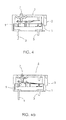
- the plunger 7, forming a one piece or monolithic construction with the switch cover 2 moves by e.g. 0.4 mm in Fig. 4a , the top wall section 5 is partially dented.
- the switch has only two contacts 3 forming a normally open micro switch.
- the normally closed contact is omitted to save material cost.
- a projection is formed on the cover 2 against which the switching component 6 bears in the rest position.
- Figures 5 to 5b show again the switch from Figures 1 to 3a .
- the plunger 7 protrudes upwards from the top wall section 5.
- the reinforcement 8 is also arranged on the topside of the wall section 5.
- the state shown in Fig. 5 corresponds to the rest position of Fig. 1 and Fig. 1a .
- the top wall section 5 has a planar shape.
- Fig. 5a the top wall section has already been dented.
- For this state shows the switching point as in Figures 2 and 2a .
- a more marked deformation of the top wall section 5 is shown in Fig. 5b , this state corresponds to the end position shown in Figures 3 and 3a .
- a material bond exists between the switch base 1 and the switch cover 2 to seal the housing.
- the material bond may be formed by gluing or by welding.
- the switch allows continued operation under water or covered by media. It can be sprayed with pressurised water such as a high-pressure cleaner without adversely affecting its function. In conjunction with a simple construction this is new for a "naked" switch (i.e. a switch without a surrounding protective construction).
- the switch is robust and tolerates strong forces of misuse.
- the simple construction means that its manufacture is very economic.
- the essential components i.e. the plunger (actuating element), bellows (sealing sleeve) and cover, are combined to form a single component (multi-function cover).
- This cover is materially bonded to the base and thereby sealed.
- the material bond between cover and base is achieved by gluing.
- the opposing respectively uninterrupted surfaces of the cover and base are pressed together. In this way a liquid adhesive is prevented from intruding into the switch during the gluing process.
- the same gluing process is used for sealing the pass-through points of the electric connections (terminals) against the base. In this way all potential intrusion paths of media into the switch are eliminated.
- the material bonding may be achieved by welding.
- Laser welding is particularly suited for this process.
- a cover of soft material e.g. an elastomer such as PE-HD or ethylene-propylene-diene-rubber (EPDM)
- soft material e.g. an elastomer such as PE-HD or ethylene-propylene-diene-rubber (EPDM)
- EPDM ethylene-propylene-diene-rubber
- the area, which absorbs the force for the switch actuation, must be sufficiently reinforced in order to allow the switching forces to be introduced without lasting deformations.
- the injection point is located in this area.
- Hard plastics are frequently easy to glue.
- the hard cover material is suited much better for further processing steps, in particular for the sealing of electric connections by casting with an adhesive or a plastic, in product design.
- the switch according to the invention shows a specially designed jump switching system which requires only a short actuating travel for switching.
Landscapes
- Push-Button Switches (AREA)
- Switch Cases, Indication, And Locking (AREA)
Applications Claiming Priority (2)
| Application Number | Priority Date | Filing Date | Title |
|---|---|---|---|
| DE102014002104 | 2014-02-15 | ||
| DE102014005433.0A DE102014005433A1 (de) | 2014-02-15 | 2014-04-10 | Mikroschalter mit einem aus Schalterbasis und Schalterdeckel ausgebildeten Gehäuse |
Publications (1)
| Publication Number | Publication Date |
|---|---|
| EP2908323A1 true EP2908323A1 (fr) | 2015-08-19 |
Family
ID=52462845
Family Applications (1)
| Application Number | Title | Priority Date | Filing Date |
|---|---|---|---|
| EP15154447.5A Withdrawn EP2908323A1 (fr) | 2014-02-15 | 2015-02-10 | Microcommutateur étanche à l'eau |
Country Status (5)
| Country | Link |
|---|---|
| US (1) | US20150235785A1 (fr) |
| EP (1) | EP2908323A1 (fr) |
| JP (1) | JP2015165496A (fr) |
| CN (1) | CN104851723A (fr) |
| DE (1) | DE102014005433A1 (fr) |
Cited By (1)
| Publication number | Priority date | Publication date | Assignee | Title |
|---|---|---|---|---|
| CN111029193A (zh) * | 2019-12-19 | 2020-04-17 | 深圳市汇创达科技股份有限公司 | 一种可触动微型开关的设置方法 |
Families Citing this family (7)
| Publication number | Priority date | Publication date | Assignee | Title |
|---|---|---|---|---|
| DE102014110602A1 (de) * | 2014-02-28 | 2015-09-03 | Johnson Electric Germany GmbH & Co. KG | Gerät mit einem beweglichen Bauteil |
| EP3046126B1 (fr) * | 2015-01-14 | 2018-10-10 | RAFI GmbH & Co. KG | Dispositif de commutation |
| TWI611701B (zh) | 2016-02-02 | 2018-01-11 | 仁寶電腦工業股份有限公司 | 防水模組 |
| JP6662537B2 (ja) * | 2016-07-22 | 2020-03-11 | アルプスアルパイン株式会社 | スイッチ装置及び該スイッチ装置の製造方法 |
| JP6958863B2 (ja) | 2018-06-27 | 2021-11-02 | 矢崎総業株式会社 | 電気的接続部の劣化度合診断装置、及び、劣化度合診断方法 |
| CN114171337B (zh) * | 2021-04-13 | 2024-09-13 | 贵州振华华联电子有限公司 | 一种行程密封微动开关 |
| CN219591293U (zh) * | 2023-03-06 | 2023-08-25 | 东莞市凯华电子有限公司 | 一种用于微动开关的防尘防水结构 |
Citations (9)
| Publication number | Priority date | Publication date | Assignee | Title |
|---|---|---|---|---|
| FR1135110A (fr) * | 1955-11-03 | 1957-04-24 | Contacteur électrique | |
| FR1402906A (fr) * | 1964-03-12 | 1965-06-18 | Crouzet Sa | Dispositif permettant de rendre hermétique les appareils tels que les contacteurs àaction brusque dont l'enceinte est en matière plastique |
| GB2023937A (en) * | 1978-06-21 | 1980-01-03 | Itw Ltd | Electric push-button switches |
| JPS57176025U (fr) * | 1981-05-01 | 1982-11-06 | ||
| DE3631405A1 (de) * | 1986-09-16 | 1988-03-17 | Felten & Guilleaume Energie | Hermetisch geschlossener permanentmagnetischer ausloeser fuer fehlerstromschutzschalter |
| EP0600634A1 (fr) | 1992-11-30 | 1994-06-08 | Burgess Micro Switch Company Ltd | Interrupteur électrique |
| EP1585155A1 (fr) | 2004-04-07 | 2005-10-12 | Eja Limited | Mécanisme interrupteur avec joint d' étanchéité |
| DE202006018987U1 (de) | 2006-12-16 | 2007-03-08 | Saia-Burgess Oldenburg Gmbh & Co. Kg | Schalter, insbesondere Mikroschalter, mit einem Gehäuse und mit zumindest einem das Gehäuse durchbrechenden Schalterstößel |
| US20080099315A1 (en) * | 2006-10-05 | 2008-05-01 | Zippy Technology Corp. | Watertight switch |
Family Cites Families (20)
| Publication number | Priority date | Publication date | Assignee | Title |
|---|---|---|---|---|
| US2743331A (en) * | 1955-01-21 | 1956-04-24 | W L Maxson Corp | Snap switch |
| US3316379A (en) * | 1965-07-29 | 1967-04-25 | Texas Instruments Inc | Seal for push button actuated device |
| US3493707A (en) * | 1968-06-10 | 1970-02-03 | Cherry Electrical Prod | Electric switch operating means |
| GB1404309A (en) * | 1971-09-09 | 1975-08-28 | Otehall Ltd | Electrical switches |
| JPS5434072U (fr) * | 1977-08-11 | 1979-03-06 | ||
| JPS62154559U (fr) * | 1986-03-20 | 1987-10-01 | ||
| JPS63128643U (fr) * | 1987-02-14 | 1988-08-23 | ||
| JPH0175932U (fr) * | 1987-11-07 | 1989-05-23 | ||
| JPH04105426U (ja) * | 1991-02-25 | 1992-09-10 | 松下電工株式会社 | スイツチ |
| GB9602320D0 (en) * | 1996-02-06 | 1996-04-03 | Burgess Micro Switch Co Ltd | Electric switch |
| DE29905710U1 (de) * | 1999-03-22 | 1999-08-12 | Petri Ag, 63743 Aschaffenburg | Elektrischer Schalter für Kraftfahrzeuge |
| JP3810237B2 (ja) * | 1999-11-19 | 2006-08-16 | 信越ポリマー株式会社 | 押釦スイッチ用キートップ部材の製造方法 |
| US20030094355A1 (en) * | 2001-11-21 | 2003-05-22 | Jan Angst | Switch cover |
| DE20303116U1 (de) * | 2003-02-20 | 2003-07-17 | Takata Petri Ag | Schalter mit selbstreinigenden Kontakten |
| JP4323363B2 (ja) * | 2004-04-01 | 2009-09-02 | アルプス電気株式会社 | スイッチ装置 |
| AT504267B1 (de) * | 2005-03-18 | 2013-06-15 | Pollmann Austria Ohg | Baueinheit mit elektrischer schaltfunktion |
| JP2007042359A (ja) * | 2005-08-02 | 2007-02-15 | Hst Kk | 押釦型スイッチ |
| TWI396114B (zh) * | 2009-04-10 | 2013-05-11 | Askey Computer Corp | 模組化鍵盤及其製法 |
| CN201741845U (zh) * | 2010-05-18 | 2011-02-09 | 富士康(昆山)电脑接插件有限公司 | 电连接器 |
| CN202796570U (zh) * | 2012-09-17 | 2013-03-13 | 宁波嘉林电子有限公司 | 同步双体微动开关 |
-
2014
- 2014-04-10 DE DE102014005433.0A patent/DE102014005433A1/de not_active Withdrawn
-
2015
- 2015-02-10 EP EP15154447.5A patent/EP2908323A1/fr not_active Withdrawn
- 2015-02-12 CN CN201510073971.3A patent/CN104851723A/zh active Pending
- 2015-02-13 US US14/622,229 patent/US20150235785A1/en not_active Abandoned
- 2015-02-13 JP JP2015026607A patent/JP2015165496A/ja active Pending
Patent Citations (9)
| Publication number | Priority date | Publication date | Assignee | Title |
|---|---|---|---|---|
| FR1135110A (fr) * | 1955-11-03 | 1957-04-24 | Contacteur électrique | |
| FR1402906A (fr) * | 1964-03-12 | 1965-06-18 | Crouzet Sa | Dispositif permettant de rendre hermétique les appareils tels que les contacteurs àaction brusque dont l'enceinte est en matière plastique |
| GB2023937A (en) * | 1978-06-21 | 1980-01-03 | Itw Ltd | Electric push-button switches |
| JPS57176025U (fr) * | 1981-05-01 | 1982-11-06 | ||
| DE3631405A1 (de) * | 1986-09-16 | 1988-03-17 | Felten & Guilleaume Energie | Hermetisch geschlossener permanentmagnetischer ausloeser fuer fehlerstromschutzschalter |
| EP0600634A1 (fr) | 1992-11-30 | 1994-06-08 | Burgess Micro Switch Company Ltd | Interrupteur électrique |
| EP1585155A1 (fr) | 2004-04-07 | 2005-10-12 | Eja Limited | Mécanisme interrupteur avec joint d' étanchéité |
| US20080099315A1 (en) * | 2006-10-05 | 2008-05-01 | Zippy Technology Corp. | Watertight switch |
| DE202006018987U1 (de) | 2006-12-16 | 2007-03-08 | Saia-Burgess Oldenburg Gmbh & Co. Kg | Schalter, insbesondere Mikroschalter, mit einem Gehäuse und mit zumindest einem das Gehäuse durchbrechenden Schalterstößel |
Cited By (1)
| Publication number | Priority date | Publication date | Assignee | Title |
|---|---|---|---|---|
| CN111029193A (zh) * | 2019-12-19 | 2020-04-17 | 深圳市汇创达科技股份有限公司 | 一种可触动微型开关的设置方法 |
Also Published As
| Publication number | Publication date |
|---|---|
| CN104851723A (zh) | 2015-08-19 |
| US20150235785A1 (en) | 2015-08-20 |
| JP2015165496A (ja) | 2015-09-17 |
| DE102014005433A1 (de) | 2015-08-20 |
Similar Documents
| Publication | Publication Date | Title |
|---|---|---|
| EP2908323A1 (fr) | Microcommutateur étanche à l'eau | |
| JP4881465B2 (ja) | 押しボタンスイッチ構造及びそれを備えた電子機器 | |
| CN101529544B (zh) | 防水型按钮开关 | |
| CN101722822B (zh) | 天窗装置 | |
| US8322296B2 (en) | Submersible apparatus including flexible waterproofing membranes | |
| US20140238980A1 (en) | Waterproofing case and method of manufacturing waterproofing case | |
| JP2014532973A (ja) | 防水及び防塵形のイルミネーションスイッチ要素 | |
| JP2009090975A (ja) | ルーフ開放構造 | |
| KR101208222B1 (ko) | 전자 장치 | |
| KR20160133432A (ko) | 디스펜서를 위한 도포기, 도포기 헤드를 포함하는 디스펜서 및 도포기 헤드를 제조하기 위한 방법 | |
| JP2006240511A (ja) | ステアリングカバー | |
| JP2013207114A (ja) | 筐体 | |
| KR20180040686A (ko) | 푸시 스위치 | |
| CN105625833A (zh) | 在致动器壳体和盖体之间的机械密封和在致动器壳体和盖体之间提供密封的方法 | |
| JP7225634B2 (ja) | サンルーフ装置 | |
| EP3664115B1 (fr) | Interrupteur à déclenchement brusque et sa méthode d'assemblage | |
| JP6144099B2 (ja) | ポンプ式噴霧容器の外気導入機構 | |
| JP2018079853A (ja) | サンルーフ装置 | |
| JP7399218B2 (ja) | 電子部品収納ケース | |
| JP2009522174A (ja) | 流体ディスペンサノズル、および該ノズルを含んだディスペンサ装置ならびにその製造方法 | |
| CN1727126B (zh) | 手操作式工具机 | |
| KR102048514B1 (ko) | 키 조립체 및 이것을 갖는 전자 장치 | |
| KR102494227B1 (ko) | 차량용 도어 씰 | |
| US20250029797A1 (en) | Button Assembly | |
| CN103187192A (zh) | 具有防水功能的按钮装置 |
Legal Events
| Date | Code | Title | Description |
|---|---|---|---|
| PUAI | Public reference made under article 153(3) epc to a published international application that has entered the european phase |
Free format text: ORIGINAL CODE: 0009012 |
|
| AK | Designated contracting states |
Kind code of ref document: A1 Designated state(s): AL AT BE BG CH CY CZ DE DK EE ES FI FR GB GR HR HU IE IS IT LI LT LU LV MC MK MT NL NO PL PT RO RS SE SI SK SM TR |
|
| AX | Request for extension of the european patent |
Extension state: BA ME |
|
| 17P | Request for examination filed |
Effective date: 20160212 |
|
| RBV | Designated contracting states (corrected) |
Designated state(s): AL AT BE BG CH CY CZ DE DK EE ES FI FR GB GR HR HU IE IS IT LI LT LU LV MC MK MT NL NO PL PT RO RS SE SI SK SM TR |
|
| 17Q | First examination report despatched |
Effective date: 20180926 |
|
| RAP1 | Party data changed (applicant data changed or rights of an application transferred) |
Owner name: JOHNSON ELECTRIC INTERNATIONAL AG |
|
| GRAP | Despatch of communication of intention to grant a patent |
Free format text: ORIGINAL CODE: EPIDOSNIGR1 |
|
| INTG | Intention to grant announced |
Effective date: 20191008 |
|
| STAA | Information on the status of an ep patent application or granted ep patent |
Free format text: STATUS: THE APPLICATION IS DEEMED TO BE WITHDRAWN |
|
| 18D | Application deemed to be withdrawn |
Effective date: 20200219 |