EP2908408A1 - Moteur moulé et climatiseur - Google Patents
Moteur moulé et climatiseur Download PDFInfo
- Publication number
- EP2908408A1 EP2908408A1 EP13846624.8A EP13846624A EP2908408A1 EP 2908408 A1 EP2908408 A1 EP 2908408A1 EP 13846624 A EP13846624 A EP 13846624A EP 2908408 A1 EP2908408 A1 EP 2908408A1
- Authority
- EP
- European Patent Office
- Prior art keywords
- lead
- stator
- molded
- wire
- stator core
- Prior art date
- Legal status (The legal status is an assumption and is not a legal conclusion. Google has not performed a legal analysis and makes no representation as to the accuracy of the status listed.)
- Granted
Links
Images









Classifications
-
- H—ELECTRICITY
- H02—GENERATION; CONVERSION OR DISTRIBUTION OF ELECTRIC POWER
- H02K—DYNAMO-ELECTRIC MACHINES
- H02K5/00—Casings; Enclosures; Supports
- H02K5/02—Casings or enclosures characterised by the material thereof
-
- F—MECHANICAL ENGINEERING; LIGHTING; HEATING; WEAPONS; BLASTING
- F04—POSITIVE - DISPLACEMENT MACHINES FOR LIQUIDS; PUMPS FOR LIQUIDS OR ELASTIC FLUIDS
- F04D—NON-POSITIVE-DISPLACEMENT PUMPS
- F04D13/00—Pumping installations or systems
- F04D13/02—Units comprising pumps and their driving means
- F04D13/06—Units comprising pumps and their driving means the pump being electrically driven
-
- H—ELECTRICITY
- H02—GENERATION; CONVERSION OR DISTRIBUTION OF ELECTRIC POWER
- H02K—DYNAMO-ELECTRIC MACHINES
- H02K15/00—Processes or apparatus specially adapted for manufacturing, assembling, maintaining or repairing of dynamo-electric machines
- H02K15/12—Impregnating, moulding insulation, heating or drying of windings, stators, rotors or machines
-
- H—ELECTRICITY
- H02—GENERATION; CONVERSION OR DISTRIBUTION OF ELECTRIC POWER
- H02K—DYNAMO-ELECTRIC MACHINES
- H02K29/00—Motors or generators having non-mechanical commutating devices, e.g. discharge tubes or semiconductor devices
- H02K29/06—Motors or generators having non-mechanical commutating devices, e.g. discharge tubes or semiconductor devices with position sensing devices
- H02K29/08—Motors or generators having non-mechanical commutating devices, e.g. discharge tubes or semiconductor devices with position sensing devices using magnetic effect devices, e.g. Hall-plates, magneto-resistors
-
- H—ELECTRICITY
- H02—GENERATION; CONVERSION OR DISTRIBUTION OF ELECTRIC POWER
- H02K—DYNAMO-ELECTRIC MACHINES
- H02K3/00—Details of windings
- H02K3/46—Fastening of windings on the stator or rotor structure
- H02K3/52—Fastening salient pole windings or connections thereto
- H02K3/521—Fastening salient pole windings or connections thereto applicable to stators only
- H02K3/522—Fastening salient pole windings or connections thereto applicable to stators only for generally annular cores with salient poles
-
- H—ELECTRICITY
- H02—GENERATION; CONVERSION OR DISTRIBUTION OF ELECTRIC POWER
- H02K—DYNAMO-ELECTRIC MACHINES
- H02K5/00—Casings; Enclosures; Supports
- H02K5/04—Casings or enclosures characterised by the shape, form or construction thereof
- H02K5/08—Insulating casings
-
- H—ELECTRICITY
- H02—GENERATION; CONVERSION OR DISTRIBUTION OF ELECTRIC POWER
- H02K—DYNAMO-ELECTRIC MACHINES
- H02K5/00—Casings; Enclosures; Supports
- H02K5/04—Casings or enclosures characterised by the shape, form or construction thereof
- H02K5/22—Auxiliary parts of casings not covered by groups H02K5/06-H02K5/20, e.g. shaped to form connection boxes or terminal boxes
- H02K5/225—Terminal boxes or connection arrangements
-
- H—ELECTRICITY
- H02—GENERATION; CONVERSION OR DISTRIBUTION OF ELECTRIC POWER
- H02K—DYNAMO-ELECTRIC MACHINES
- H02K2203/00—Specific aspects not provided for in the other groups of this subclass relating to the windings
- H02K2203/03—Machines characterised by the wiring boards, i.e. printed circuit boards or similar structures for connecting the winding terminations
-
- H—ELECTRICITY
- H02—GENERATION; CONVERSION OR DISTRIBUTION OF ELECTRIC POWER
- H02K—DYNAMO-ELECTRIC MACHINES
- H02K2203/00—Specific aspects not provided for in the other groups of this subclass relating to the windings
- H02K2203/12—Machines characterised by the bobbins for supporting the windings
-
- H—ELECTRICITY
- H02—GENERATION; CONVERSION OR DISTRIBUTION OF ELECTRIC POWER
- H02K—DYNAMO-ELECTRIC MACHINES
- H02K2211/00—Specific aspects not provided for in the other groups of this subclass relating to measuring or protective devices or electric components
- H02K2211/03—Machines characterised by circuit boards, e.g. pcb
Definitions
- the present invention relates to a molded motor and an air conditioner.
- a conventional molded motor is configured so that a stator core and a winding are covered with a mold resin such as BMC (Bulk Molding Compound) by injecting the mold resin into a molding die that accommodates therein the stator core.
- a mold resin such as BMC (Bulk Molding Compound)
- BMC Bulk Molding Compound
- a regulating member is formed in a molding die, and the regulating member engages with an outer peripheral lower side of a stator core so that the lateral motion thereof cannot be made, thereby regulating lateral movements of the stator core in an accommodating concave portion of the molding die.
- Patent Literature 1 Japanese Patent No. 4351929
- the present invention has been achieved in view of the above problem, and an objective of the present invention is to provide a molded motor and an air conditioner that can achieve further improvement in quality.
- the present invention relates to a molded motor that includes a stator made by molding with a thermosetting resin.
- the stator includes: a stator core formed by stacking magnetic steel plates; an insulation portion applied to the stator core; a winding applied to the insulation portion; and a power supply terminal to which a power supply line for supplying power to the winding is connected.
- a plurality of inner wall protrusions formed at axial ends of the insulation inner wall on a counter wire-connection side of the stator core and abutting on a die being used when the stator is molded, are provided in a circumferential direction of the stator core.
- inner-wall protrusions formed at the end of an insulation inner wall on a counter wire-connection side are supported by a die when molded; and an installation surface of the inner-wall protrusions is provided inside of a bracket fitting portion. Therefore, when a molded motor has been assembled, penetration of water into the molded stator is suppressed, thereby enabling further quality improvement to be achieved.
- FIG. 1 is a perspective view illustrating a state before attaching a sensor board 30 to a lead-wire wiring component 1 of a molded motor 100 according to an embodiment of the present invention.
- FIG. 2 is a perspective view of a lead-out component 70 for pressing a sensor lead wire group 23.
- FIG. 3 is a perspective view of a lead-out component 60 for a lead wire partition.
- FIG. 4 is a perspective view of a lead-out component 80 for pressing a power lead wire group 24.
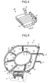
- FIG. 5 is a detailed diagram of the lead-wire wiring component 1.
- FIG. 6 is a detailed diagram of a fourth frame portion 12d of a guide frame 12.
- FIG. 7 is a detailed diagram of a lead-wire introducing and holding portion 17 of the lead-wire wiring component 1.
- FIG. 1 is a perspective view illustrating a state before attaching a sensor board 30 to a lead-wire wiring component 1 of a molded motor 100 according to an embodiment of the present invention.
- FIG. 2 is
- FIG. 8 is a detailed diagram of a temporary fixing component 40.
- FIG. 9 is a diagram illustrating a state of attaching the respective lead-out components (60, 70, and 80) to the temporary fixing component 40.
- FIG. 10 is a perspective view before the lead-wire wiring component 1 is attached to a stator 50.
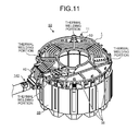
- FIG. 11 is a perspective view after the lead-wire wiring component 1 is attached to the stator 50.
- FIG. 12 illustrates a plurality of inner wall protrusions 56 formed on an insulation inner wall 52 of a stator core 57.
- FIG. 13 illustrates a state of detaching the temporary fixing component 40.
- FIG. 14 is a perspective view of a molded stator 90 as viewed from a side opposite to a load.
- FIG. 15 is a perspective view illustrating a molded stator 90A molded by a die core-bar portion having a stepped portion 131.
- FIG. 16 is a sectional view illustrating the molded stator 90A molded by the die core-bar portion having the stepped portion 131.
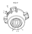
- FIG. 17 is a perspective view illustrating a molded stator 90B molded by a die core-bar portion having a claw 135.
- FIG. 18 is a sectional view illustrating the molded stator 90B molded by the die core-bar portion having the claw.
- FIG. 19 is a perspective view illustrating a molded stator 90C molded by a die core-bar portion having a protrusion 136.
- FIG. 20 is a plan view illustrating the molded stator 90C molded by the die core-bar portion having the protrusion 136.
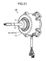
- FIG. 21 is a perspective view of the molded motor 100 having a rotor shaft 102 incorporated in the molded stator 90.
- FIG. 22 is a configuration diagram of an air conditioner having the molded motor 100 incorporated therein.
- the stator 50 is configured to include a stator portion 59 and the lead-wire wiring component 1.
- the stator portion 59 is configured to include the stator core 57 formed by punching a magnetic steel plate in a belt-like shape and stacking the magnetic steel plates by swaging, welding, bonding, and the like in an axial direction of the rotor shaft 102 (see FIG. 21 ); an insulation portion 54 formed by integrally forming a thermoplastic resin such as PBT (polybutylene terephthalate) with the stator core 57, or after forming the stator core 57, assembling the integrally formed stator core 57 to the stator portion 59; and a winding 55 formed by winding a magnet wire around the insulation portion 54.
- PBT polybutylene terephthalate
- One terminal of the magnet wire of each phase is bonded by fusing or soldering to a power supply terminal 58, to which power from outside is supplied.
- the other terminal forms a neutral point with terminals of all phases that are brought together.
- the windings 55 of the same phase are connected by a connecting line.
- an outside of an axial end face of the stator core 57, that is, a side including the power supply terminal 58 is referred to as "wire connection side"; and an opposite side thereof is referred to as "counter wire-connection side".
- An insulation outer wall 53 of the stator core 57 prevents the winding 55 from falling over toward an outer peripheral side of the stator core 57; and the insulation inner wall 52 of the stator core 57 prevents the winding 55 from falling over toward an inner peripheral side of the stator core 57.
- plural columnar shaped (for example, octagonal column shaped) attachment pins 51 for attaching the sensor board 30 and the lead-wire wiring component 1 to the stator portion 59 are provided at an axial end 53a of the insulation outer wall 53.
- a plurality of inner wall protrusions 56 extending in an axial direction are provided at an axial end 52a of the insulation inner wall 52.
- the inner wall protrusions 56 are provided roughly at an equal interval in a circumferential direction of the stator core 57; and as an example, four inner wall protrusions 56 are provided in FIG. 12 .
- These inner wall protrusions 56 abut on the die core-bar portion (the stepped portion 131, the claw 135, or the protrusion 136 described later), when molding the stator 50.
- the inner wall protrusions 56 are preferably formed so that the axial end thereof becomes equal to or lower than a height of a tip of the axial end 53a of the insulation outer wall 53 of the stator core 57.
- the tip of the axial end 53a of the insulation outer wall 53 is formed so that the height thereof is slightly higher than an axial maximum height of the winding 55.
- the winding 55 is formed so that the axial height thereof (see FIG. 16 ) becomes lower as approaching the insulation inner wall 52 from the insulation outer wall 53.
- the stator 50 when the stator 50 is provided in the die core-bar portion in a state where the counter wire-connection side of the stator core 57 is directed downward, the winding 55 does not come into contact with the die core-bar portion and the stator core 57 can be stably placed.
- the height of the inner wall protrusion 56 can ensure a sufficient distance from the axial end of the inner wall protrusion 56 to the winding 55 and is equal to or lower than the height of the insulation outer wall 53.
- FIG. 1 illustrates the lead-wire wiring component 1, a lead-wire wiring assembly 20, the temporary fixing component 40, the lead-out component 70, and the sensor board 30.
- the lead-wire wiring assembly 20 is configured to include the power lead wire group 24 that supplies power to the winding 55, the sensor lead wire group 23, a board-in connector 26 connected to a terminal of the power lead wire group 24, and a board-in connector 25 connected to a terminal of the sensor lead wire group 23.
- a terminal 26a is provided in the board-in connector 26; and a terminal 25a is provided in the board-in connector 25.
- the length of the sensor lead wire group 23 from a lead-wire lead-out portion 140 to the board-in connector 25 is set to be longer than the length of the power lead wire group 24 from the lead-wire lead-out portion 140 to the board-in connector 26.
- a counter-stator side surface 34, on which a power supply pattern is formed and a stator side surface 35, on which electronic components such as a sensor circuit 33 are mounted (see FIG. 9 ) on the sensor board 30, function independently. Therefore, according to the present embodiment, these board surfaces do not need to be joined electrically; and a non-through board can be used as the sensor board 30, thereby enabling the cost to be low.
- the board-in connector 26 is provided on the stator side surface of the sensor board 30; and the terminal 26a provided in the board-in connector 26 protrudes to the counter-stator side surface 34 of the sensor board 30 through a terminal insertion hole 36 (see FIG. 1 ) formed in the sensor board 30 (see FIG. 10 ). Because the terminal insertion hole 36 and a power-supply terminal hole 32 are connected by a power-supply wiring pattern provided on the sensor board 30, the power lead wire group 24 and the winding 55 are electrically joined by soldering these terminals.
- the board-in connector 25 is provided on the counter-stator side surface 34 of the sensor board 30; and the terminal 25a provided in the board-in connector 25 protrudes to the stator side surface 35 of the sensor board 30 via a terminal insertion hole 37 (see FIG. 1 ) formed in the sensor board 30 (see FIG. 9 ). Because the terminal insertion hole 36 and the power-supply terminal hole 32 are connected by a wiring pattern provided on the sensor board 30, the sensor lead wire group 23 and the electronic components such as the sensor circuit 33 are electrically joined by soldering these terminals.
- the lead-wire wiring component 1 illustrated in FIG. 5 is configured to mainly include a first frame 14, a second frame 15, and a plurality of joining portions 16.
- the first frame 14 is formed in a substantially circular thin shape and is provided on an extended line, which extends in the axial direction, of the insulation outer wall 53 on the wire connection side of the stator core 57.
- a plurality of insertion holes 10, a plurality of movement suppressing pins 11, a plurality of board pressing protrusions 5, and a plurality of outer-periphery pressing portions 13 are formed on the first frame 14; and the lead-wire introducing and holding portion 17 is also formed. Note that the number of the insertion holes 10, the movement suppressing pins 11, the board pressing protrusions 5, and the outer-periphery pressing portions 13 is not limited to the number illustrated in FIG. 5 .
- the attachment pin 51 on the wire connection side is inserted into the insertion hole 10; and as illustrated in FIG. 11 , when the lead-wire wiring component 1 is attached to the stator portion 59, the attachment pin 51 is welded in the insertion hole 10.
- the movement suppressing pins 11 are provided in a projecting manner in the axial direction from the first frame 14 so as to come into contact with the axial end of the insulation outer wall 53 (see FIG. 11 ) in order to reduce displacement of the stator 50 toward the wire connection side when molding the stator 50.
- the board pressing protrusions 5 are provided in a projecting manner in the axial direction from the first frame 14 so as to come into contact with the counter-stator side surface 34 of the sensor board 30 (see FIG. 10 ) in order to reduce displacement of the sensor board 30 toward the wire connection side when molding the stator 50.
- a tip portion of the outer-periphery pressing portion 13 is bent toward the side of the stator portion 59 at a predetermined position, after the outer-periphery pressing portion 13 extends radially outward from the first frame 14 so as to come into contact with an outer peripheral edge 38 of the sensor board 30 (see FIG. 1 ) in order to prevent the sensor board 30 from moving radially (particularly in the outer circumferential direction of the stator 50), when assembling the sensor board 30 to the lead-wire wiring component 1.
- Two outer-periphery pressing portions 13 are provided in the lead-wire wiring component 1; and as illustrated in FIG. 1 , the sensor board 30 is desirably provided with a notch 39, to which the outer-periphery pressing portion 13 is fitted, on the outer peripheral edge 38 thereof. According to the configuration, the outer-periphery pressing portion 13 enters into a depressed portion of the notch 39 (see FIG. 10 ); and thus a circumferential displacement of the sensor board 30 is also reduced. As a result, a work for assembling the lead-wire wiring component 1 attached with the sensor board 30 to the stator portion 59 is facilitated, thereby achieving productivity improvement and cost reduction; and quality improvement is achieved along with the productivity improvement.
- the lead-wire introducing and holding portion 17 is configured to include the guide frame 12, a plurality of locking portions 9, a plurality of wiring protrusions (7a to 7c), a plurality of wiring grooves (18a to 18e), and two temporary fixing-component installation grooves 8.
- the position of the sensor board 30 and the position of the lead-wire lead-out portion 140 in the axial direction differ (see FIG. 16 ).
- the lead wire groups (23 and 24) are fixed to the lead-wire lead-out portion 140 provided near the outer periphery of the stator portion 59 by the temporary fixing component 40.
- These lead wire groups (23 and 24) need to be wired from the lead-wire lead-out portion 140 toward the wire connection side of the stator core 57 along the outer periphery of the stator core 57, and guided to the sensor board 30 when they have reached near the lead-wire wiring component 1.
- the guide frame 12 illustrated in FIG. 7 is for bending the lead wire groups (23 and 24) provided from the lead-wire lead-out portion 140 to the lead-wire wiring component 1 along the outer periphery of the stator core 57 toward the center of the stator portion 59 and guiding the lead wire groups (23 and 24) to the sensor board 30.
- the guide frame 12 is configured to include a first frame portion 12a, second frame portions 12b, and a third frame portion 12c, and an opening 2 is formed in a central part thereof.
- the first frame portion 12a is provided in a part of the first frame 14.
- the first frame portion 12a is provided with a plurality of wiring protrusions 7b and 7c formed in a projecting manner toward an opposite side of the stator portion 59 (a counter-stator portion side).
- a wiring groove is formed between these protrusions, and of these grooves, for example, in four wiring grooves 18c on the left side in FIG. 7 , each of four lead wires of five lead wires constituting the sensor lead wire group 23 is respectively held.
- the fifth wiring groove 18d from the left in FIG. 7 a groove provided between the wiring protrusion 7b and the wiring protrusion 7c
- one of the five lead wires constituting the sensor lead wire group 23 and one of three lead wires constituting the power lead wire group 24 are overlapped vertically and are held (see FIG. 10 ).
- each of two lead wires of the three lead wires constituting the power lead wire group 24 is respectively held in two wiring grooves 18e on the right side in FIG. 7 .
- the second frame portions 12b extend from the first frame 14 radially outward; and the third frame portion 12c is provided at the ends thereof.
- the third frame portion 12c is provided so as to connect the ends of two second frame portions 12b, and for example, is provided radially more outside than an axially extended line of the outer periphery of the stator core 57.
- the third frame portion 12c is provided with a plurality of wiring protrusions 7a formed in a projecting manner toward the counter-stator portion side.
- a slightly smaller fourth frame portion 12d is also provided inside of the third frame portion.
- the fourth frame portion 12d is provided with a plurality of wiring protrusions 7g formed in a projecting manner toward the counter-stator portion side; and is provided with a plurality of wiring grooves 18f.
- the third frame portion 12c and the fourth frame portion 12d constitute a bent wiring portion 6.
- the third frame portion 12c bends and guides the sensor lead wire group 23, wired in the axial direction from the lead-wire lead-out portion 140 to the inside of the lead-wire wiring component 1.
- the fourth frame portion 12d bends and guides the power lead wire group 24, wired in the axial direction from the lead-wire lead-out portion 140 to the inside of the lead-wire wiring component 1.
- the sensor lead wire group 23 is wired on this side of FIG. 7 ; and the power lead wire group 24 is wired between the third frame portion 12c and the fourth frame portion 12d.
- the fourth frame portion 12d is provided on the center side of the stator than the third bent portion 12c, the distance from the center of the lead-wire wiring component 1 to the power lead wire group 24 becomes shorter than the distance from the center of the lead-wire wiring component 1 to the sensor lead wire group 23.
- the fourth frame portion 12d is provided nearer to the end face on the wire connection side of the stator core 57 than the third frame portion 12c, the distance from the sensor lead wire group 23 bent toward the lead-wire wiring component 1 by the third frame portion 12c to the end face on the wire connection side of the stator core 57 (or an outer periphery of the winding 55) becomes longer than the distance from the power lead wire group 24 bent toward the lead-wire wiring component 1 by the fourth frame portion 12d to the end face on the wire connection side of the stator core 57. In this manner, in the bent wiring portion 6, the sensor lead wire group 23 and the power lead wire group 24 are wired so that the distance from the lead-wire wiring component 1 and the distance from the end face on the wire connection side of the stator core 57 respectively differ.
- the first groove from the left side in FIG. 7 and the first groove from the right side in FIG. 7 are the temporary fixing-component installation grooves 8 for installing the temporary fixing component 40 (see FIG. 8 ).
- the locking portions 9 are provided in the third frame portion 12c with a predetermined distance therebetween and formed in a hooked shape, with the tip thereof being formed in a hook-like shape for locking the temporary fixing component 40.
- the second frame 15 illustrated in FIG. 5 is formed in a substantially circular thin shape, which is smaller than an inner diameter of the first frame 14 and larger than an outer diameter of a bearing insertion-surface forming portion 137 (see FIG. 16 ) of the die core-bar portion, and is provided so as to face a die core-bar-portion end face 138 inside of the first frame 14.
- the second frame 15 is formed with a plurality of molding-die core-bar portion installation legs 4 formed in a projecting manner toward the stator portion 59; and the molding-die core-bar portion installation leg 4 is formed with a plurality of board holding portions 3 formed in a projecting manner radially outward.
- the molding-die core-bar portion installation legs 4 extend axially on a surface of the second frame 15 on the side of the stator core 57, so that each tip portion thereof comes into contact with the die core-bar portion (the die core-bar-portion end face 138 illustrated in FIGS. 16 , 17 , and 19 ), in order to prevent the sensor board 30 from being displaced due to a pressure when molding the stator 50.
- the board holding portion 3 is provided in a projecting manner radially outward of the molding-die core-bar portion installation legs 4 so as to engage with the stator side surface 35 of the sensor board 30 and hold the sensor board 30 (see FIG. 9 ) in order to prevent radial and axial displacement of the sensor board 30 when molding the stator 50.
- a plurality of joining portions 16a, 16b, and 16c radially extending from the second frame 15 toward the first frame 14 are provided between the first frame 14 and the second frame 15.
- the first frame 14 and the second frame 15 are integrally formed by these joining portions 16a, 16b, and 16c.
- a plurality of wiring protrusions 7e formed in a projecting manner toward the counter-stator portion side and a plurality of wiring protrusions 7e formed in a projecting manner toward the stator portion side are alternately provided in each of the joining portions 16a. With these wiring protrusions 7e, the respective lead wires constituting the sensor lead wire group 23 are held so as to be disposed with a predetermined distance therebetween.
- the respective lead wires may be fixed in a state where respective lead wires come into contact with each other when molding the stator 50.
- a void may be formed at a portion where the respective lead wires come into contact with each other.
- water penetrating from a boundary surface between the lead-wire lead-out portion 140 (see FIG. 10 ) and the mold resin may seep into the voids between the respective lead wires and reach the sensor board 30.
- the respective lead wires constituting the sensor lead wire group 23 are held by the joining portions 16a, the respective lead wires do not come into contact with each other when molding the stator 50; and the generation of void can be reduced. Accordingly, the water penetrating from the boundary surface between the lead-wire lead-out portion 140 and the mold resin does not seep into the voids between the lead wires to reach the sensor board 30; and improvement in quality can be achieved as a result.
- a plurality of wiring protrusions 7f formed in a projecting manner toward the counter-stator portion side are similarly provided in the joining portion 16b. Therefore, water penetrating from the lead-wire lead-out portion 140 into the molded stator 90 does not seep into through the voids between the respective lead wires constituting the power lead wire group 24 and does not reach the sensor board 30; and thus improvement in quality can be achieved as a result.
- FIG. 9 is a diagram illustrating a state where the sensor board 30 is assembled to the lead-wire wiring component 1.
- the sensor lead wire group 23 is wired to the lead-wire wiring component 1 to which the sensor board 30 has been assembled; and the sensor lead wire group 23 wired to the third frame portion 12c is then wired to the wiring grooves 18c and 18d of the first frame portion 12a, and then pulled round in an arc-like shape in a clockwise direction as viewed from the counter-stator portion side of the lead-wire wiring component 1.
- the board-in connector 25 is then assembled to the sensor board 30.
- the power lead wire group 24 is then wired to the fourth frame portion 12d; and the power lead wire group 24 wired to the fourth frame portion 12d is wired to the wiring grooves 18d and 18e of the first frame portion 12a and pulled round in an arc-like shape in a counterclockwise direction as viewed from the counter-stator portion side of the lead-wire wiring component 1.
- the board-in connector 26 is then assembled to the sensor board 30.
- the sensor lead wire group 23 between from the first frame portion 12a to the sensor board 30 is wired alternately, as illustrated in FIG. 10 , to the counter-stator portion side and to the stator portion side.
- the sensor lead wire group 23 can be fastened to a predetermined position in the axial direction; and the contact between the sensor lead wire group 23 and the winding 55 can be prevented when molding the stator 50. Further, it can be prevented that the sensor lead wire group 23 protrudes toward the outer periphery side of the molded stator 90, thereby enabling improvement in the quality.
- the four wiring protrusions 7b illustrated in FIG. 7 are formed so that surfaces coming into contact with the respective lead wires of the sensor lead wire group 23 are directed toward a guide direction of the sensor lead wire group 23 (in FIG. 7 , the left side of the first frame portion 12a).
- This configuration facilitates the wiring of the sensor lead wire group 23 so as to improve manufacturing productivity, thereby enabling the improvements in quality and costs to be further reduced.
- the two wiring protrusions 7c are formed so that the surfaces coming into contact with the respective lead wires of the power lead wire group 24 are directed toward a guide direction of the power lead wire group 24 (in FIG. 7 , the right side of the first frame portion 12a).
- This configuration facilitates the wiring of the power lead wire group 24 so as to improve productivity, thereby enabling the improvements in the cost reduction and quality.
- the sensor lead wire group 23 and the power lead wire group 24 are branched respectively in the different directions so as to prevent overlapping of the respective lead wires constituting the branched lead wire groups (23 and 24), thereby enabling reductions in wiring length of the respective lead wires to the absolute minimum length. Further, because a space can be ensured between the adjacent lead wires, penetration of water into the sensor board 30 can be prevented, thereby enabling an improvement in quality.
- the temporary fixing component 40 illustrated in FIG. 8 is configured to include an installation surface 43 formed in a substantially rectangular plate-like shape, on which the lead-out component 70 is provided; locking holes 44 formed in the installation surface 43; joining portions 45 provided at opposite ends of the installation surface 43 and extending in the axial direction; installation legs 41 provided at the ends of the joining portions 45 and locked by the temporary fixing-component installation grooves 8 (see FIG. 7 ); and locking holes 42 respectively formed in the joining portions 45 in the axial direction.
- a longitudinal width W1 of the installation surface 43 is formed to be longer than a longitudinal width W2 of the lead-out component 70 illustrated in FIG. 2 .
- An engaging portion 72 provided in the lead-out component 70 is inserted into the locking hole 44.
- An end of the locking portion 9 (see FIG. 5 ) provided in the lead-wire introducing and holding portion 17 is inserted into the locking hole 42.
- the lead-out component 70 illustrated in FIG. 2 includes a stator-mold upper-die pressing surface 71 formed in a substantially rectangular plate-like shape; and a fitting portion 73 provided on short-side end faces of the stator-mold upper-die pressing surface 71.
- a plurality of grooves 74 for holding the sensor lead wire group 23 are formed on a lead-wire-side end face 71b of the stator-mold upper-die pressing surface 71.
- the installation surface 43 of the temporary fixing component 40 in FIG. 8 comes into contact with a counter-lead wire-side end face 71a of the stator-mold upper-die pressing surface 71.
- the fitting portion 73 is formed in an L-shape; and an engaging portion 62 of the lead-out component 60 illustrated in FIG. 3 is attached to the fitting portion 73. At one end of the fitting portion 73, the engaging portion 72 that is inserted into the locking hole 44 formed in the installation surface 43 of the temporary fixing component 40 so as to engage with the installation surface 43 is formed.
- the lead-out component 60 illustrated in FIG. 3 includes a lead-wire fixing portion 63 in a substantially rectangular plate-like shape; the engaging portion 62 locked to the fitting portion 73 of the lead-out component 70; and the engaging portion 61 locked to a fitting portion 81 of the lead-out component 80.
- a plurality of grooves 64 for holding the sensor lead wire group 23 are formed on a sensor lead-wire-side end face 63a of the lead-out component 60.
- a plurality of grooves 65 for holding the power lead wire group 24 are formed on a power lead-wire-side end face 63b of the lead-out component 60.
- the lead-out component 80 illustrated in FIG. 4 includes a power lead-wire fixing portion 82 in a substantially rectangular plate-like shape; and the fitting portion 81 locked to an engaging portion 61 of the lead-out component 60.
- a plurality of grooves 83 for holding the power lead wire group 24 are formed on a power lead-wire-side end face 82a of the power lead-wire fixing portion 82.
- the lead-wire lead-out portion 140 is assembled to the lead-wire wiring component 1 via the temporary fixing component 40 such that the lead wires from the bent wiring portion 6 of the lead-wire wiring component 1 to the lead-wire lead-out portion 140 do not sag and do not become short.
- the installation legs 41 of the temporary fixing component 40 are fitted into the temporary-fixing-component installation grooves 8 of the lead-wire introducing and holding portion 17. Accordingly, the temporary fixing component 40 is temporarily fixed to the lead-wire introducing and holding portion 17.
- the engaging portions 72 of the lead-out component 70 are then inserted into the locking holes 44 of the temporary fixing component 40. Accordingly, the lead-out component 70 is assembled to the lead-wire wiring component 1 via the temporary fixing component 40; and the lead-out component 70 is provided at a position away from the lead-wire wiring component 1 by a predetermined distance.
- the sensor lead wire group 23 is placed in the grooves 74 of the lead-out component 70, while having an appropriate tension applied so that the respective lead wires of the sensor lead wire group 23 do not come into contact with each other.
- the sensor lead wire group 23 wired in this manner is illustrated in FIG. 9 .
- the lead-out component 60 is fitted into an L-shaped fitting portion 73 of the lead-out component 70, while sliding the lead-out component 60 from the center of the lead-wire wiring component 1 toward outside.
- the lead-out component 60 is, thus, assembled to the lead-out component 70.
- the sliding direction of the lead-out component 60 is a direction from the center of the lead-wire wiring component 1 toward outside, when assembling the lead-out component 60 to the lead-out component 70, the sensor lead wire group 23 is pulled in the sliding direction of the lead-out component 60. Therefore, the sensor lead wire group 23 is further pulled so as to correct the respective distortions of the lead wires of the sensor lead wire group 23. Accordingly, the respective lead wires do not come into contact with each other when molding the stator 50; and the voids between the respective lead wires described above can be reduced.
- the sensor lead wire group 23 is placed in the grooves 65 of the lead-out component 60, while being applied with an appropriate tension so that the respective lead wires of the power lead wire group 24 do not come into contact with each other.
- the fitting portion 81 of the lead-out component 80 is fitted into the engaging portion 61 of the lead-out component 60, while sliding the fitting portion 81 from the center of the lead-wire wiring component 1 toward outside. Accordingly, the fitting portion 81 is locked to the engaging portion 61; and the lead-out component 80 is assembled to the lead-out component 60.
- the sensor lead wire group 23 is pulled in the sliding direction of the lead-out component 80. Therefore, the sensor lead wire group 23 is further pulled so as to correct the respective distortions of the lead wires of the sensor lead wire group 23.
- water penetrating into the molded stator 90 from the side of the lead-wire lead-out portion 140 does not seep into the voids between the respective lead wires constituting the sensor lead wire group 23 so as to reach the sensor board 30, which is the effect as when assembling the lead-out component 60 to the lead-out component 70. This, thereby, enables the improvement in quality.
- the lead-wire wiring assembly 20 is assembled to the lead-wire wiring component 1.
- a tube 21 that protects the respective lead wires is fixed by a unifying band 22.
- the unifying band 22 when the unifying band 22 is applied can be set after the stator 50 has been molded.
- the lead-wire wiring component 1, in which the sensor board 30 and the lead-wire wiring assembly 20 are assembled, is assembled to the wire connection side of the stator core 57 by inserting the attachment pins 51 (see FIG. 10 ) provided on the stator core 57 into the insertion holes 10 of the lead-wire wiring component 1 and the insertion holes 31 of the sensor board 30. As illustrated in FIG. 11 , the lead-wire wiring component 1 is fixed by welding the attachment pins 51 protruding on the counter stator side of the lead-wire wiring component 1. Temporary assembly of the stator 50 is thus complete.
- the attachment pin 51 has substantially a regular octagonal columnar shape, corner portions of the attachment pin 51 comes into contact with the circular insertion holes 10 and 31. Accordingly, even if the attachment pin 51 and the insertion holes 10 and 31 are fitted to each other more tightly, because a contact portion is small when compared to a case where a circular pin is used, the resistance when inserting the attachment pin 51 can be reduced. As a result, the sensor board 30 can be accurately assembled to the stator portion 59, enabling the improvement in quality.
- the stator 50 is provided in the die as illustrated in FIGS. 16 , 17 , and 19 .
- the temporary fixing component 40 is detached from the lead-wire lead-out portion 140 (see FIG. 13 ) by unlocking the locking portion 9 from the lead-wire introducing and holding portion 17 or cutting the locking portion 9
- molding is performed so as to obtain the molded stator 90 (see FIG. 14 ).
- the lead-wire wiring component 1 is configured to ensure a predetermined amount of space between the sensor board 30 and the lead-wire wiring component 1 (that is, between the first frame 14 and the counter-stator side surface 34; and between the second frame 15 and the counter-stator side surface 34).
- the contacts can be reduced between the lead-wire wiring component 1 being a resin molded product and the sensor board 30. Accordingly, water seeping on and penetrating from the boundary surface between the lead-wire wiring component 1 and the mold resin does not reach the sensor board 30, thereby enabling the improvement in proof strength against deterioration of the circuit portion of the sensor board 30 and in quality.
- the lead-wire lead-out portion 140 When molding the stator 50, the lead-wire lead-out portion 140 is pushed out from the center of the stator 50 to outside by the molding pressure. Therefore, the position of the lead-wire lead-out portion 140 fixed by the temporary fixing component 40 is maintained without contacting the stator core 57. Accordingly, a clearance between the respective lead wires when the lead-wire lead-out portion 140 is fixed by the temporary fixing component 40 does not become narrow; and the water seeping on the boundary surface between the lead-wire lead-out portion 140 and the mold resin and penetrating into the molded stator 90 can be reduced, thereby enabling to improve the quality. Further, because the detached temporary fixing component 40 can be reused again, cost can be reduced.
- FIG. 16 illustrates the die core-bar portion (a core bar portion of a lower molding die) having the stepped portion 131 for supporting the inner wall protrusions 56 when molding the stator 50.
- the core bar portion of the lower molding die includes a stator-core inner-diameter fitting portion 134 formed substantially in the same diameter as the inner diameter of the stator 50 and provided on the inner diameter side of the stator 50; a bracket fitting portion 130 having a larger diameter than the stator-core inner-diameter fitting portion 134; and the stepped portion 131 having a diameter smaller than the bracket fitting portion 130 and larger than the stator-core inner-diameter fitting portion 134, which forms an inner-diameter protrusion installation surface 98 on which the inner wall protrusions 56 are provided.
- FIG. 15 illustrates a bracket fitting surface 95, a bracket installation surface 96, an inner periphery 97 of the stepped portion 131, and the inner-diameter protrusion installation surface 98 of an opening 94 of the molded stator 90A formed by the die core-bar portion illustrated in FIG. 16 . That is, in the opening 94 of the molded stator 90A, the bracket installation surface 96 and the inner-diameter protrusion installation surface 98 positioned closer on the stator core side than the bracket installation surface 96 and having a diameter smaller than the bracket fitting surface 95 and larger than the inner diameter of the stator core are formed.
- the inner wall protrusions 56 are provided on an axial end surface of the inner-diameter protrusion installation surface 98 as illustrated in FIG. 16 .
- a regulating member provided in a die is provided on an outer periphery of a stator. Therefore, when molding the stator, a boundary surface is formed between a stator core (or an insulation portion of a stator core) supported by the regulating member and a mold resin; and the boundary surface becomes a penetration path for water into the molded stator, which may cause quality degradation.
- the inner wall protrusions 56 provided on the insulation inner wall 52 are provided on the surface forming the inner-diameter protrusion installation surface 98 of the stepped portion 131. That is, the outer periphery of the stator 50 does not need to be supported by a die (a conventional regulating member); and a boundary surface is not formed between the stator core and the mold resin on a shell of the molded stator 90A, in a state where a bracket 103 is assembled to the bracket fitting portion 130 of the stator when assembly of the molded motor. Accordingly, penetration of water into the molded stator 90A is reduced, thereby enabling the quality to be improved.
- FIG. 18 illustrates a die core-bar portion having the protrusion 135 for supporting the inner wall protrusions 56.
- the die core-bar portion illustrated in FIG. 16 is different in that the claw 135 is provided instead of the stepped portion 131.
- the claw 135 is formed in the axial direction and closer on the stator side than the surface forming the bracket installation surface 96 and in a projecting manner by a predetermined amount on a radially outer peripheral side than a circumferential surface constituting an inner periphery 132 of the stator core, so that the inner wall protrusions 56 can be provided; and the inner wall protrusions 56 are provided thereon.
- FIG. 17 illustrates the bracket fitting surface 95, the bracket installation surface 96, and concave portions 99 of the opening 94 of the molded stator 90B formed by the die core-bar portion illustrated in FIG. 18 .
- the concave portion 99 is formed by the claw 135. That is, in the opening 94 of the molded stator 90B, there are formed the bracket installation surface 96, and the concave portions 99 extending from the bracket installation surface 96 toward the stator core side and extending radially outside from the inner periphery 132 of the stator core, the concave portions 99 being formed in plural in the circumferential direction.
- the inner wall protrusions 56 are provided on bottom surfaces of the concave portions 99, the bottom being perpendicular to the axial direction, as illustrated in FIG. 18 .
- effects identical to those of the molded stator 90A can be acquired in a state where the bracket 103 is assembled to the bracket fitting portion 130 of the stator when assembling the molded motor.
- FIG. 20 a die core-bar portion having the protrusions 136 for supporting the inner wall protrusions 56 is illustrated in FIG. 20 .
- the protrusions 136 are formed in plural in the circumferential direction at a position away from a circumferential surface of the stator-core inner-diameter fitting portion 134 constituting the inner periphery 132 of the stator core, so that the inner wall protrusions 56 can be provided; and is formed in a projecting manner from the end face forming the bracket installation surface 96 in a direction toward the axial direction of the stator core side.
- the inner wall protrusions 56 are provided on the projecting end face.
- FIG. 19 illustrates the bracket fitting surface 95, the bracket installation surface 96, and holes 93 of the opening 94 of the molded stator 90C formed by the die core-bar portion illustrated in FIG. 20 .
- the holes 93 are formed by the protrusion 136. That is, in the opening 94 of the molded stator 90C, there are formed the bracket installation surface 96, and the holes 93 positioned radially more outside than the inner periphery 132 of the stator core and extending from the bracket installation surface 96 toward the stator core side, the holes 93, a plurality thereof, being formed in the circumferential direction.
- the inner wall protrusions 56 are provided on the bottom surfaces of the holes 93, the bottom being perpendicular to the axial direction, as illustrated in FIG. 20 .
- the molded stator 90C thus, has effects identical to those of the molded stator 90A in a case where the bracket 103 is assembled to the bracket fitting portion 130 of the stator when assembly the molded motor.
- the molded motor 100 that can have excellent productivity and excellent quality and can reduce the cost.
- the bracket 103 illustrated in FIG. 21 is provided with a waterproof rubber 101 in order to prevent the water from penetrating between the rotor shaft 102 and the bracket 103.
- FIG. 22 illustrates an air conditioner having the molded motor 100 according to the present embodiment incorporated therein.
- the air conditioner includes an indoor unit 110 and an outdoor unit 120 connected to the indoor unit 110.
- the indoor unit 110 and the outdoor unit 120 are provided with the molded motor 100 as a drive source for an air blower.
- the quality of the air conditioner can be improved.
- the sensor lead wire group 23 is pulled round in the clockwise direction on the lead-wire wiring component 1; and the power lead wire group 24 is pulled round in the counterclockwise direction on the lead-wire wiring component 1.
- the pulling directions of the respective lead wires can be reversed.
- the power lead wire group 24 is formed shorter than the sensor lead wire group 23; however, the sensor lead wire group 23 can be formed shorter than the power lead wire group 24. In this case, although voltage drop increases due to the resistance of the power lead wire group 24, the effects described above can be acquired.
- the molded motor 100 is made by molding with a thermosetting resin, and includes the stator 50 that includes the stator core 57 formed by stacking magnetic steel plates; the insulation portion 54 applied to the stator core 57; the winding 55 applied to the insulation portion 54; and the power supply terminal 58 to which the power supply line (24) for supplying power to the winding 55 is connected.
- inner wall protrusions 56 On the insulation inner wall 52 provided on the inner diameter side of the insulation portion 54, inner wall protrusions 56, a plurality thereof, which are provided in the circumferential direction of the stator core 57, are formed at axial ends 52a of the insulation inner wall 52 on the counter wire-connection side of the stator core 57, abutting on the die core-bar portion (the stepped portions 131, the claws 135, and the protrusions 136) used when the stator 50 is molded.
- the outer periphery of the stator 50 does not need to be supported by the conventional regulating member; and a boundary surface is not formed between the stator core 57 and the mold resin. Accordingly, penetration of water into the molded stator 90 is reduced, thereby enabling the quality improvement.
- the molded motor and the air conditioner according to the embodiment of the present invention are only an example of the contents of the present invention.
- the embodiment can be combined with other well-known techniques, and it is needless to mention that the present invention can be configured while modifying it without departing from the scope of the invention, such as omitting a part of its configuration.
- the present invention is applicable to a molded motor and an air conditioner, and is particularly useful as an invention that can improve further in quality.
- 1 lead-wire wiring component 2 opening, 3 board holding portion, 4 molding-die core-bar portion installation leg, 5 board pressing protrusion, 6 bent wiring portion, 7a, 7b, 7c, 7e, 7f, 7g wiring protrusion, 8 temporary fixing-component installation groove, 9 locking portion, 10 insertion hole, 11 movement suppressing pin, 12 guide frame, 12a first frame portion, 12b second frame portion, 12c third frame portion, 12d fourth frame portion, 13 outer-periphery pressing portion, 14 first frame, 15 second frame, 16a, 16b, 16c joining portion, 17 lead-wire introducing and holding portion, 18a, 18b, 18c, 18d, 18e, 18f wiring groove, 20 lead-wire wiring assembly, 21 tube, 22 unifying band, 23 sensor lead wire group, 24 power lead wire group, 25 board-in connector, 25a terminal, 26 board-in connector, 26a terminal, 30 sensor board, 31 insertion hole, 32 power-supply terminal hole, 33 sensor circuit, 34 counter-stator side surface, 35 stator side surface, 36
Landscapes
- Engineering & Computer Science (AREA)
- Power Engineering (AREA)
- Manufacturing & Machinery (AREA)
- Mechanical Engineering (AREA)
- General Engineering & Computer Science (AREA)
- Motor Or Generator Frames (AREA)
- Insulation, Fastening Of Motor, Generator Windings (AREA)
- Other Air-Conditioning Systems (AREA)
- Manufacture Of Motors, Generators (AREA)
Applications Claiming Priority (2)
| Application Number | Priority Date | Filing Date | Title |
|---|---|---|---|
| JP2012228317 | 2012-10-15 | ||
| PCT/JP2013/073562 WO2014061359A1 (fr) | 2012-10-15 | 2013-09-02 | Moteur moulé et climatiseur |
Publications (3)
| Publication Number | Publication Date |
|---|---|
| EP2908408A1 true EP2908408A1 (fr) | 2015-08-19 |
| EP2908408A4 EP2908408A4 (fr) | 2016-06-29 |
| EP2908408B1 EP2908408B1 (fr) | 2019-05-01 |
Family
ID=50487936
Family Applications (1)
| Application Number | Title | Priority Date | Filing Date |
|---|---|---|---|
| EP13846624.8A Not-in-force EP2908408B1 (fr) | 2012-10-15 | 2013-09-02 | Moteur moulé et climatiseur |
Country Status (5)
| Country | Link |
|---|---|
| US (1) | US9705375B2 (fr) |
| EP (1) | EP2908408B1 (fr) |
| JP (1) | JP5951036B2 (fr) |
| CN (2) | CN104718684B (fr) |
| WO (1) | WO2014061359A1 (fr) |
Cited By (2)
| Publication number | Priority date | Publication date | Assignee | Title |
|---|---|---|---|---|
| EP4195472A3 (fr) * | 2021-12-10 | 2023-08-02 | Black & Decker, Inc. | Ensemble moteur à rotor externe |
| DE102020203193B4 (de) | 2019-03-26 | 2024-09-26 | Kabushiki Kaisha Toyota Jidoshokki | Elektrischer kompressor |
Families Citing this family (23)
| Publication number | Priority date | Publication date | Assignee | Title |
|---|---|---|---|---|
| AU2013403563B2 (en) * | 2013-10-22 | 2017-04-20 | Mitsubishi Electric Corporation | Molded stator, molded electric motor, and air conditioner |
| CN105659476B (zh) * | 2013-10-24 | 2018-03-06 | 三菱电机株式会社 | 电动机、空调机及电器设备 |
| WO2016006077A1 (fr) * | 2014-07-10 | 2016-01-14 | 三菱電機株式会社 | Stator de moteur électrique, moteur électrique, et appareil de conditionnement d'air |
| JP6282347B2 (ja) * | 2014-07-11 | 2018-02-21 | 三菱電機株式会社 | 電動機の固定子、電動機、および空気調和機 |
| CN204810027U (zh) * | 2014-08-01 | 2015-11-25 | 日本电产高科电机株式会社 | 马达 |
| WO2016063427A1 (fr) * | 2014-10-24 | 2016-04-28 | 三菱電機株式会社 | Stator de moteur électrique, moteur électrique, et conditionneur d'air |
| CN107078590B (zh) * | 2014-10-24 | 2019-05-14 | 三菱电机株式会社 | 电动机的定子、电动机以及空调 |
| EP3032719B1 (fr) * | 2014-12-11 | 2019-03-13 | Johnson Electric International AG | Moteur synchrone, stator de moteur, pompe et appareil de nettoyage |
| WO2017000113A1 (fr) * | 2015-06-29 | 2017-01-05 | 广东威灵电机制造有限公司 | Moteur, pompe de lavage, lave-vaisselle et procédé de fabrication de moteur |
| WO2017130539A1 (fr) * | 2016-01-27 | 2017-08-03 | ダイキン工業株式会社 | Moteur |
| JP6202173B2 (ja) * | 2016-01-27 | 2017-09-27 | ダイキン工業株式会社 | モータ |
| CN109075647B (zh) * | 2016-05-11 | 2020-11-03 | 日立汽车系统株式会社 | 旋转电机 |
| JP6150925B1 (ja) * | 2016-05-18 | 2017-06-21 | 三菱電機株式会社 | 回転電機 |
| US10897174B2 (en) * | 2016-06-28 | 2021-01-19 | Mitsubishi Electric Corporation | Stator, motor, and air conditioner |
| KR102090830B1 (ko) * | 2016-08-04 | 2020-03-18 | 미쓰비시덴키 가부시키가이샤 | 전동기 및 공기 조화 장치 |
| KR102559314B1 (ko) | 2016-08-25 | 2023-07-26 | 한온시스템 주식회사 | 클러스터 조립체 및 이를 포함하는 전동식 압축기 |
| JP6844168B2 (ja) * | 2016-09-20 | 2021-03-17 | アイシン精機株式会社 | ステータおよびステータ製造方法 |
| DE102019107509A1 (de) * | 2018-04-26 | 2019-10-31 | Hanon Systems | Vorrichtung zum Antreiben eines Verdichters |
| KR102510385B1 (ko) * | 2018-05-18 | 2023-03-16 | 한온시스템 주식회사 | 모터의 전자소자 고정 장치 및 이를 포함하는 모터 |
| CN112117853B (zh) * | 2019-06-19 | 2022-05-06 | 尼得科电机(青岛)有限公司 | 电机的定子组件及其制造方法,电机的定子 |
| WO2021205652A1 (fr) * | 2020-04-10 | 2021-10-14 | 三菱電機株式会社 | Moteur électrique, dispositif d'enroulement de fil conducteur, et procédé de fabrication d'un moteur électrique |
| CN118282106A (zh) * | 2022-12-30 | 2024-07-02 | 南京泉峰科技有限公司 | 电动工具和电机 |
| JP7629583B1 (ja) * | 2024-07-23 | 2025-02-13 | マブチモーター株式会社 | ハウジング、モータ及びブロア |
Family Cites Families (20)
| Publication number | Priority date | Publication date | Assignee | Title |
|---|---|---|---|---|
| US4015154A (en) * | 1974-12-23 | 1977-03-29 | Sony Corporation | Motor and method for making same |
| US4495450A (en) | 1982-12-29 | 1985-01-22 | Sanyo Electric Co., Ltd. | Control device for brushless motor |
| JPS6032534A (ja) * | 1983-08-02 | 1985-02-19 | Sanyo Electric Co Ltd | 小型電動機 |
| JPH07107724A (ja) * | 1993-10-04 | 1995-04-21 | Matsushita Electric Ind Co Ltd | ブラシレスモータのステータ |
| JP3601964B2 (ja) | 1998-03-24 | 2004-12-15 | 三菱電機株式会社 | 電動機 |
| JP3499788B2 (ja) | 1999-12-20 | 2004-02-23 | 三菱電機株式会社 | 電動機 |
| JP3269498B2 (ja) | 2000-03-17 | 2002-03-25 | 松下電器産業株式会社 | 電動機のステータの製造方法 |
| JP3679305B2 (ja) | 2000-03-23 | 2005-08-03 | 東芝キヤリア株式会社 | 冷媒圧縮機 |
| JP3560953B2 (ja) | 2002-02-20 | 2004-09-02 | 三菱電機株式会社 | 電動機の固定子及び電動機及びモールド電動機及び送風機及び空気調和機及び電動機の固定子の製造方法 |
| JP3923871B2 (ja) | 2002-08-29 | 2007-06-06 | 三菱電機株式会社 | 電動機の固定子及びモールド電動機及び送風機及び空気調和機 |
| JP4351929B2 (ja) * | 2004-02-24 | 2009-10-28 | 愛知電機株式会社 | 電動機の樹脂モールド方法および樹脂モールド方法に用いる成形金型 |
| JP4915098B2 (ja) * | 2006-01-06 | 2012-04-11 | パナソニック株式会社 | モールドモータの製造方法 |
| JP4982439B2 (ja) | 2008-06-30 | 2012-07-25 | 株式会社日立製作所 | 圧粉成形体 |
| JP4901819B2 (ja) * | 2008-07-16 | 2012-03-21 | 三菱電機株式会社 | モールド固定子及びポンプ及び給湯機及び電動機及び空気調和機 |
| JP5463663B2 (ja) | 2008-12-15 | 2014-04-09 | トヨタ自動車株式会社 | 固定子構造及び固定子製造方法 |
| JP5132631B2 (ja) | 2009-05-25 | 2013-01-30 | 三菱電機株式会社 | 電動機の固定子及び電動機及び空気調和機及び電動機の製造方法 |
| JP5505077B2 (ja) | 2010-05-19 | 2014-05-28 | トヨタ自動車株式会社 | 固定子製造方法 |
| JP2012120261A (ja) | 2010-11-29 | 2012-06-21 | Mitsubishi Electric Corp | モールド成型治具、モールド成型方法及びステータ |
| CN103314506B (zh) * | 2011-01-18 | 2015-11-25 | 三菱电机株式会社 | 模制电动机和空调机 |
| TWM424701U (en) * | 2011-12-01 | 2012-03-11 | Lidashi Industry Co Ltd | Motor stator |
-
2013
- 2013-09-02 EP EP13846624.8A patent/EP2908408B1/fr not_active Not-in-force
- 2013-09-02 WO PCT/JP2013/073562 patent/WO2014061359A1/fr not_active Ceased
- 2013-09-02 JP JP2014541988A patent/JP5951036B2/ja not_active Expired - Fee Related
- 2013-09-02 CN CN201380053452.XA patent/CN104718684B/zh not_active Expired - Fee Related
- 2013-09-02 US US14/433,405 patent/US9705375B2/en not_active Expired - Fee Related
- 2013-10-15 CN CN201320635764.9U patent/CN203632370U/zh not_active Expired - Fee Related
Cited By (4)
| Publication number | Priority date | Publication date | Assignee | Title |
|---|---|---|---|---|
| DE102020203193B4 (de) | 2019-03-26 | 2024-09-26 | Kabushiki Kaisha Toyota Jidoshokki | Elektrischer kompressor |
| EP4195472A3 (fr) * | 2021-12-10 | 2023-08-02 | Black & Decker, Inc. | Ensemble moteur à rotor externe |
| US12463502B2 (en) | 2021-12-10 | 2025-11-04 | Black & Decker Inc. | Outer-rotor motor assembly |
| US12549065B2 (en) | 2021-12-10 | 2026-02-10 | Black & Decker Inc. | Power tool with compact outer-rotor motor assembly |
Also Published As
| Publication number | Publication date |
|---|---|
| CN104718684A (zh) | 2015-06-17 |
| WO2014061359A1 (fr) | 2014-04-24 |
| JP5951036B2 (ja) | 2016-07-13 |
| EP2908408B1 (fr) | 2019-05-01 |
| JPWO2014061359A1 (ja) | 2016-09-05 |
| US20150263581A1 (en) | 2015-09-17 |
| CN104718684B (zh) | 2017-11-07 |
| CN203632370U (zh) | 2014-06-04 |
| EP2908408A4 (fr) | 2016-06-29 |
| US9705375B2 (en) | 2017-07-11 |
Similar Documents
| Publication | Publication Date | Title |
|---|---|---|
| EP2908408B1 (fr) | Moteur moulé et climatiseur | |
| CN105027394B (zh) | 电动机的模制定子、电动机、空调机以及电动机的模制定子的制造方法 | |
| JP4906807B2 (ja) | 電動機の固定子及び電動機及び空気調和機 | |
| CN203632477U (zh) | 电动机和空调机 | |
| CN204216696U (zh) | 模制定子、模制电动机和空调机 | |
| CN106416010B (zh) | 电动机的定子、电动机以及空调机 | |
| CN203896077U (zh) | 模制定子、模制电动机和空调机 | |
| US10284043B2 (en) | Stator for electric motor, electric motor, and air conditioner | |
| JP2014082847A (ja) | モールド電動機および空気調和機 | |
| US20160241104A1 (en) | Electric motor, air conditioner, and electric apparatus | |
| CN105659475B (zh) | 模制定子、模制电动机和空调机 | |
| JP2014087219A (ja) | モールド電動機および空気調和機 | |
| JP2008178260A (ja) | 電動機の固定子及び電動機及び空気調和機及び電動機の製造方法 | |
| CN204179842U (zh) | 定子、电动机和空调机 | |
| CN203800712U (zh) | 模制定子、模制电动机和空调机 | |
| CN107078590A (zh) | 电动机的定子、电动机以及空调 | |
| JP2014082848A (ja) | モールド電動機および空気調和機 | |
| WO2014147797A1 (fr) | Stator de moteur électrique ainsi que procédé de fabrication de celui-ci, moteur électrique, et appareil de conditionnement d'air |
Legal Events
| Date | Code | Title | Description |
|---|---|---|---|
| PUAI | Public reference made under article 153(3) epc to a published international application that has entered the european phase |
Free format text: ORIGINAL CODE: 0009012 |
|
| 17P | Request for examination filed |
Effective date: 20150420 |
|
| AK | Designated contracting states |
Kind code of ref document: A1 Designated state(s): AL AT BE BG CH CY CZ DE DK EE ES FI FR GB GR HR HU IE IS IT LI LT LU LV MC MK MT NL NO PL PT RO RS SE SI SK SM TR |
|
| AX | Request for extension of the european patent |
Extension state: BA ME |
|
| DAX | Request for extension of the european patent (deleted) | ||
| RA4 | Supplementary search report drawn up and despatched (corrected) |
Effective date: 20160530 |
|
| RIC1 | Information provided on ipc code assigned before grant |
Ipc: H02K 29/08 20060101ALN20160523BHEP Ipc: H02K 5/08 20060101ALI20160523BHEP Ipc: H02K 5/02 20060101ALN20160523BHEP Ipc: F04D 13/06 20060101ALN20160523BHEP Ipc: H02K 3/34 20060101AFI20160523BHEP Ipc: H02K 5/22 20060101ALN20160523BHEP Ipc: H02K 15/12 20060101ALN20160523BHEP Ipc: H02K 3/52 20060101ALI20160523BHEP |
|
| STAA | Information on the status of an ep patent application or granted ep patent |
Free format text: STATUS: EXAMINATION IS IN PROGRESS |
|
| 17Q | First examination report despatched |
Effective date: 20171220 |
|
| GRAP | Despatch of communication of intention to grant a patent |
Free format text: ORIGINAL CODE: EPIDOSNIGR1 |
|
| STAA | Information on the status of an ep patent application or granted ep patent |
Free format text: STATUS: GRANT OF PATENT IS INTENDED |
|
| RIC1 | Information provided on ipc code assigned before grant |
Ipc: H02K 15/12 20060101ALN20181022BHEP Ipc: H02K 29/08 20060101ALN20181022BHEP Ipc: F04D 13/06 20060101ALN20181022BHEP Ipc: H02K 3/52 20060101ALI20181022BHEP Ipc: H02K 5/08 20060101ALI20181022BHEP Ipc: H02K 3/34 20060101AFI20181022BHEP Ipc: H02K 5/22 20060101ALN20181022BHEP Ipc: H02K 5/02 20060101ALN20181022BHEP |
|
| INTG | Intention to grant announced |
Effective date: 20181114 |
|
| GRAS | Grant fee paid |
Free format text: ORIGINAL CODE: EPIDOSNIGR3 |
|
| GRAA | (expected) grant |
Free format text: ORIGINAL CODE: 0009210 |
|
| STAA | Information on the status of an ep patent application or granted ep patent |
Free format text: STATUS: THE PATENT HAS BEEN GRANTED |
|
| AK | Designated contracting states |
Kind code of ref document: B1 Designated state(s): AL AT BE BG CH CY CZ DE DK EE ES FI FR GB GR HR HU IE IS IT LI LT LU LV MC MK MT NL NO PL PT RO RS SE SI SK SM TR |
|
| REG | Reference to a national code |
Ref country code: GB Ref legal event code: FG4D |
|
| REG | Reference to a national code |
Ref country code: CH Ref legal event code: EP Ref country code: AT Ref legal event code: REF Ref document number: 1128233 Country of ref document: AT Kind code of ref document: T Effective date: 20190515 |
|
| REG | Reference to a national code |
Ref country code: DE Ref legal event code: R096 Ref document number: 602013054794 Country of ref document: DE |
|
| REG | Reference to a national code |
Ref country code: IE Ref legal event code: FG4D |
|
| REG | Reference to a national code |
Ref country code: NL Ref legal event code: MP Effective date: 20190501 |
|
| REG | Reference to a national code |
Ref country code: LT Ref legal event code: MG4D |
|
| PG25 | Lapsed in a contracting state [announced via postgrant information from national office to epo] |
Ref country code: NL Free format text: LAPSE BECAUSE OF FAILURE TO SUBMIT A TRANSLATION OF THE DESCRIPTION OR TO PAY THE FEE WITHIN THE PRESCRIBED TIME-LIMIT Effective date: 20190501 Ref country code: HR Free format text: LAPSE BECAUSE OF FAILURE TO SUBMIT A TRANSLATION OF THE DESCRIPTION OR TO PAY THE FEE WITHIN THE PRESCRIBED TIME-LIMIT Effective date: 20190501 Ref country code: LT Free format text: LAPSE BECAUSE OF FAILURE TO SUBMIT A TRANSLATION OF THE DESCRIPTION OR TO PAY THE FEE WITHIN THE PRESCRIBED TIME-LIMIT Effective date: 20190501 Ref country code: ES Free format text: LAPSE BECAUSE OF FAILURE TO SUBMIT A TRANSLATION OF THE DESCRIPTION OR TO PAY THE FEE WITHIN THE PRESCRIBED TIME-LIMIT Effective date: 20190501 Ref country code: NO Free format text: LAPSE BECAUSE OF FAILURE TO SUBMIT A TRANSLATION OF THE DESCRIPTION OR TO PAY THE FEE WITHIN THE PRESCRIBED TIME-LIMIT Effective date: 20190801 Ref country code: PT Free format text: LAPSE BECAUSE OF FAILURE TO SUBMIT A TRANSLATION OF THE DESCRIPTION OR TO PAY THE FEE WITHIN THE PRESCRIBED TIME-LIMIT Effective date: 20190901 Ref country code: FI Free format text: LAPSE BECAUSE OF FAILURE TO SUBMIT A TRANSLATION OF THE DESCRIPTION OR TO PAY THE FEE WITHIN THE PRESCRIBED TIME-LIMIT Effective date: 20190501 Ref country code: AL Free format text: LAPSE BECAUSE OF FAILURE TO SUBMIT A TRANSLATION OF THE DESCRIPTION OR TO PAY THE FEE WITHIN THE PRESCRIBED TIME-LIMIT Effective date: 20190501 Ref country code: SE Free format text: LAPSE BECAUSE OF FAILURE TO SUBMIT A TRANSLATION OF THE DESCRIPTION OR TO PAY THE FEE WITHIN THE PRESCRIBED TIME-LIMIT Effective date: 20190501 |
|
| PG25 | Lapsed in a contracting state [announced via postgrant information from national office to epo] |
Ref country code: BG Free format text: LAPSE BECAUSE OF FAILURE TO SUBMIT A TRANSLATION OF THE DESCRIPTION OR TO PAY THE FEE WITHIN THE PRESCRIBED TIME-LIMIT Effective date: 20190801 Ref country code: GR Free format text: LAPSE BECAUSE OF FAILURE TO SUBMIT A TRANSLATION OF THE DESCRIPTION OR TO PAY THE FEE WITHIN THE PRESCRIBED TIME-LIMIT Effective date: 20190802 Ref country code: LV Free format text: LAPSE BECAUSE OF FAILURE TO SUBMIT A TRANSLATION OF THE DESCRIPTION OR TO PAY THE FEE WITHIN THE PRESCRIBED TIME-LIMIT Effective date: 20190501 Ref country code: RS Free format text: LAPSE BECAUSE OF FAILURE TO SUBMIT A TRANSLATION OF THE DESCRIPTION OR TO PAY THE FEE WITHIN THE PRESCRIBED TIME-LIMIT Effective date: 20190501 |
|
| REG | Reference to a national code |
Ref country code: AT Ref legal event code: MK05 Ref document number: 1128233 Country of ref document: AT Kind code of ref document: T Effective date: 20190501 |
|
| PG25 | Lapsed in a contracting state [announced via postgrant information from national office to epo] |
Ref country code: IS Free format text: LAPSE BECAUSE OF FAILURE TO SUBMIT A TRANSLATION OF THE DESCRIPTION OR TO PAY THE FEE WITHIN THE PRESCRIBED TIME-LIMIT Effective date: 20190901 |
|
| PG25 | Lapsed in a contracting state [announced via postgrant information from national office to epo] |
Ref country code: EE Free format text: LAPSE BECAUSE OF FAILURE TO SUBMIT A TRANSLATION OF THE DESCRIPTION OR TO PAY THE FEE WITHIN THE PRESCRIBED TIME-LIMIT Effective date: 20190501 Ref country code: AT Free format text: LAPSE BECAUSE OF FAILURE TO SUBMIT A TRANSLATION OF THE DESCRIPTION OR TO PAY THE FEE WITHIN THE PRESCRIBED TIME-LIMIT Effective date: 20190501 Ref country code: RO Free format text: LAPSE BECAUSE OF FAILURE TO SUBMIT A TRANSLATION OF THE DESCRIPTION OR TO PAY THE FEE WITHIN THE PRESCRIBED TIME-LIMIT Effective date: 20190501 Ref country code: CZ Free format text: LAPSE BECAUSE OF FAILURE TO SUBMIT A TRANSLATION OF THE DESCRIPTION OR TO PAY THE FEE WITHIN THE PRESCRIBED TIME-LIMIT Effective date: 20190501 Ref country code: SK Free format text: LAPSE BECAUSE OF FAILURE TO SUBMIT A TRANSLATION OF THE DESCRIPTION OR TO PAY THE FEE WITHIN THE PRESCRIBED TIME-LIMIT Effective date: 20190501 Ref country code: DK Free format text: LAPSE BECAUSE OF FAILURE TO SUBMIT A TRANSLATION OF THE DESCRIPTION OR TO PAY THE FEE WITHIN THE PRESCRIBED TIME-LIMIT Effective date: 20190501 |
|
| REG | Reference to a national code |
Ref country code: DE Ref legal event code: R097 Ref document number: 602013054794 Country of ref document: DE |
|
| PG25 | Lapsed in a contracting state [announced via postgrant information from national office to epo] |
Ref country code: SM Free format text: LAPSE BECAUSE OF FAILURE TO SUBMIT A TRANSLATION OF THE DESCRIPTION OR TO PAY THE FEE WITHIN THE PRESCRIBED TIME-LIMIT Effective date: 20190501 Ref country code: IT Free format text: LAPSE BECAUSE OF FAILURE TO SUBMIT A TRANSLATION OF THE DESCRIPTION OR TO PAY THE FEE WITHIN THE PRESCRIBED TIME-LIMIT Effective date: 20190501 |
|
| PLBE | No opposition filed within time limit |
Free format text: ORIGINAL CODE: 0009261 |
|
| STAA | Information on the status of an ep patent application or granted ep patent |
Free format text: STATUS: NO OPPOSITION FILED WITHIN TIME LIMIT |
|
| PG25 | Lapsed in a contracting state [announced via postgrant information from national office to epo] |
Ref country code: TR Free format text: LAPSE BECAUSE OF FAILURE TO SUBMIT A TRANSLATION OF THE DESCRIPTION OR TO PAY THE FEE WITHIN THE PRESCRIBED TIME-LIMIT Effective date: 20190501 |
|
| 26N | No opposition filed |
Effective date: 20200204 |
|
| PG25 | Lapsed in a contracting state [announced via postgrant information from national office to epo] |
Ref country code: PL Free format text: LAPSE BECAUSE OF FAILURE TO SUBMIT A TRANSLATION OF THE DESCRIPTION OR TO PAY THE FEE WITHIN THE PRESCRIBED TIME-LIMIT Effective date: 20190501 |
|
| PG25 | Lapsed in a contracting state [announced via postgrant information from national office to epo] |
Ref country code: MC Free format text: LAPSE BECAUSE OF FAILURE TO SUBMIT A TRANSLATION OF THE DESCRIPTION OR TO PAY THE FEE WITHIN THE PRESCRIBED TIME-LIMIT Effective date: 20190501 Ref country code: SI Free format text: LAPSE BECAUSE OF FAILURE TO SUBMIT A TRANSLATION OF THE DESCRIPTION OR TO PAY THE FEE WITHIN THE PRESCRIBED TIME-LIMIT Effective date: 20190501 |
|
| REG | Reference to a national code |
Ref country code: CH Ref legal event code: PL |
|
| PG25 | Lapsed in a contracting state [announced via postgrant information from national office to epo] |
Ref country code: IE Free format text: LAPSE BECAUSE OF NON-PAYMENT OF DUE FEES Effective date: 20190902 Ref country code: LU Free format text: LAPSE BECAUSE OF NON-PAYMENT OF DUE FEES Effective date: 20190902 Ref country code: CH Free format text: LAPSE BECAUSE OF NON-PAYMENT OF DUE FEES Effective date: 20190930 Ref country code: LI Free format text: LAPSE BECAUSE OF NON-PAYMENT OF DUE FEES Effective date: 20190930 |
|
| REG | Reference to a national code |
Ref country code: BE Ref legal event code: MM Effective date: 20190930 |
|
| PG25 | Lapsed in a contracting state [announced via postgrant information from national office to epo] |
Ref country code: BE Free format text: LAPSE BECAUSE OF NON-PAYMENT OF DUE FEES Effective date: 20190930 |
|
| PG25 | Lapsed in a contracting state [announced via postgrant information from national office to epo] |
Ref country code: CY Free format text: LAPSE BECAUSE OF FAILURE TO SUBMIT A TRANSLATION OF THE DESCRIPTION OR TO PAY THE FEE WITHIN THE PRESCRIBED TIME-LIMIT Effective date: 20190501 |
|
| PG25 | Lapsed in a contracting state [announced via postgrant information from national office to epo] |
Ref country code: HU Free format text: LAPSE BECAUSE OF FAILURE TO SUBMIT A TRANSLATION OF THE DESCRIPTION OR TO PAY THE FEE WITHIN THE PRESCRIBED TIME-LIMIT; INVALID AB INITIO Effective date: 20130902 Ref country code: MT Free format text: LAPSE BECAUSE OF FAILURE TO SUBMIT A TRANSLATION OF THE DESCRIPTION OR TO PAY THE FEE WITHIN THE PRESCRIBED TIME-LIMIT Effective date: 20190501 |
|
| REG | Reference to a national code |
Ref country code: DE Ref legal event code: R084 Ref document number: 602013054794 Country of ref document: DE |
|
| REG | Reference to a national code |
Ref country code: GB Ref legal event code: 746 Effective date: 20220510 |
|
| PG25 | Lapsed in a contracting state [announced via postgrant information from national office to epo] |
Ref country code: MK Free format text: LAPSE BECAUSE OF FAILURE TO SUBMIT A TRANSLATION OF THE DESCRIPTION OR TO PAY THE FEE WITHIN THE PRESCRIBED TIME-LIMIT Effective date: 20190501 |
|
| P01 | Opt-out of the competence of the unified patent court (upc) registered |
Effective date: 20230512 |
|
| PGFP | Annual fee paid to national office [announced via postgrant information from national office to epo] |
Ref country code: GB Payment date: 20230727 Year of fee payment: 11 |
|
| PGFP | Annual fee paid to national office [announced via postgrant information from national office to epo] |
Ref country code: FR Payment date: 20230808 Year of fee payment: 11 Ref country code: DE Payment date: 20230802 Year of fee payment: 11 |
|
| REG | Reference to a national code |
Ref country code: DE Ref legal event code: R119 Ref document number: 602013054794 Country of ref document: DE |
|
| GBPC | Gb: european patent ceased through non-payment of renewal fee |
Effective date: 20240902 |
|
| PG25 | Lapsed in a contracting state [announced via postgrant information from national office to epo] |
Ref country code: DE Free format text: LAPSE BECAUSE OF NON-PAYMENT OF DUE FEES Effective date: 20250401 |
|
| PG25 | Lapsed in a contracting state [announced via postgrant information from national office to epo] |
Ref country code: GB Free format text: LAPSE BECAUSE OF NON-PAYMENT OF DUE FEES Effective date: 20240902 |
|
| PG25 | Lapsed in a contracting state [announced via postgrant information from national office to epo] |
Ref country code: FR Free format text: LAPSE BECAUSE OF NON-PAYMENT OF DUE FEES Effective date: 20240930 |