EP2908923B1 - Filtervorrichtung - Google Patents
Filtervorrichtung Download PDFInfo
- Publication number
- EP2908923B1 EP2908923B1 EP13780066.0A EP13780066A EP2908923B1 EP 2908923 B1 EP2908923 B1 EP 2908923B1 EP 13780066 A EP13780066 A EP 13780066A EP 2908923 B1 EP2908923 B1 EP 2908923B1
- Authority
- EP
- European Patent Office
- Prior art keywords
- filter
- filter element
- casing
- housing
- fluid
- Prior art date
- Legal status (The legal status is an assumption and is not a legal conclusion. Google has not performed a legal analysis and makes no representation as to the accuracy of the status listed.)
- Active
Links
Images


Classifications
-
- B—PERFORMING OPERATIONS; TRANSPORTING
- B01—PHYSICAL OR CHEMICAL PROCESSES OR APPARATUS IN GENERAL
- B01D—SEPARATION
- B01D29/00—Filters with filtering elements stationary during filtration, e.g. pressure or suction filters, not covered by groups B01D24/00 - B01D27/00; Filtering elements therefor
- B01D29/60—Filters with filtering elements stationary during filtration, e.g. pressure or suction filters, not covered by groups B01D24/00 - B01D27/00; Filtering elements therefor integrally combined with devices for controlling the filtration
- B01D29/606—Filters with filtering elements stationary during filtration, e.g. pressure or suction filters, not covered by groups B01D24/00 - B01D27/00; Filtering elements therefor integrally combined with devices for controlling the filtration by pressure measuring
-
- B—PERFORMING OPERATIONS; TRANSPORTING
- B01—PHYSICAL OR CHEMICAL PROCESSES OR APPARATUS IN GENERAL
- B01D—SEPARATION
- B01D29/00—Filters with filtering elements stationary during filtration, e.g. pressure or suction filters, not covered by groups B01D24/00 - B01D27/00; Filtering elements therefor
- B01D29/11—Filters with filtering elements stationary during filtration, e.g. pressure or suction filters, not covered by groups B01D24/00 - B01D27/00; Filtering elements therefor with bag, cage, hose, tube, sleeve or like filtering elements
- B01D29/13—Supported filter elements
- B01D29/15—Supported filter elements arranged for inward flow filtration
- B01D29/21—Supported filter elements arranged for inward flow filtration with corrugated, folded or wound sheets
-
- B—PERFORMING OPERATIONS; TRANSPORTING
- B01—PHYSICAL OR CHEMICAL PROCESSES OR APPARATUS IN GENERAL
- B01D—SEPARATION
- B01D2201/00—Details relating to filtering apparatus
- B01D2201/40—Special measures for connecting different parts of the filter
- B01D2201/403—Special measures for connecting different parts of the filter allowing dilatation, e.g. by heat
-
- F—MECHANICAL ENGINEERING; LIGHTING; HEATING; WEAPONS; BLASTING
- F01—MACHINES OR ENGINES IN GENERAL; ENGINE PLANTS IN GENERAL; STEAM ENGINES
- F01N—GAS-FLOW SILENCERS OR EXHAUST APPARATUS FOR MACHINES OR ENGINES IN GENERAL; GAS-FLOW SILENCERS OR EXHAUST APPARATUS FOR INTERNAL-COMBUSTION ENGINES
- F01N2610/00—Adding substances to exhaust gases
- F01N2610/14—Arrangements for the supply of substances, e.g. conduits
- F01N2610/1426—Filtration means
-
- F—MECHANICAL ENGINEERING; LIGHTING; HEATING; WEAPONS; BLASTING
- F01—MACHINES OR ENGINES IN GENERAL; ENGINE PLANTS IN GENERAL; STEAM ENGINES
- F01N—GAS-FLOW SILENCERS OR EXHAUST APPARATUS FOR MACHINES OR ENGINES IN GENERAL; GAS-FLOW SILENCERS OR EXHAUST APPARATUS FOR INTERNAL-COMBUSTION ENGINES
- F01N2610/00—Adding substances to exhaust gases
- F01N2610/14—Arrangements for the supply of substances, e.g. conduits
- F01N2610/1486—Means to prevent the substance from freezing
-
- F—MECHANICAL ENGINEERING; LIGHTING; HEATING; WEAPONS; BLASTING
- F01—MACHINES OR ENGINES IN GENERAL; ENGINE PLANTS IN GENERAL; STEAM ENGINES
- F01N—GAS-FLOW SILENCERS OR EXHAUST APPARATUS FOR MACHINES OR ENGINES IN GENERAL; GAS-FLOW SILENCERS OR EXHAUST APPARATUS FOR INTERNAL-COMBUSTION ENGINES
- F01N3/00—Exhaust or silencing apparatus having means for purifying, rendering innocuous, or otherwise treating exhaust
- F01N3/08—Exhaust or silencing apparatus having means for purifying, rendering innocuous, or otherwise treating exhaust for rendering innocuous
- F01N3/10—Exhaust or silencing apparatus having means for purifying, rendering innocuous, or otherwise treating exhaust for rendering innocuous by thermal or catalytic conversion of noxious components of exhaust
- F01N3/18—Exhaust or silencing apparatus having means for purifying, rendering innocuous, or otherwise treating exhaust for rendering innocuous by thermal or catalytic conversion of noxious components of exhaust characterised by methods of operation; Control
- F01N3/20—Exhaust or silencing apparatus having means for purifying, rendering innocuous, or otherwise treating exhaust for rendering innocuous by thermal or catalytic conversion of noxious components of exhaust characterised by methods of operation; Control specially adapted for catalytic conversion
- F01N3/206—Adding periodically or continuously substances to exhaust gases for promoting purification, e.g. catalytic material in liquid form, NOx reducing agents
- F01N3/2066—Selective catalytic reduction [SCR]
Definitions
- the invention relates to a filter device having the features in the preamble of claim 1.
- Filter devices with at least one filter element which can be accommodated in a housing and can be flowed through by a corresponding system pressure or fluid operating pressure are commercially available and are widely used, for example, in hydraulic systems in system branches through which hydraulic oil flows.
- a support tube preferably made of plastic material, is provided, which provides perforations provided the support of the filter material used counter to the predetermined flow direction of the fluid.
- the filter material is placed as a pleated filter mat around a fluid-permeable support tube, and the respective filter element is provided with end caps.
- the DE 10 2010 061 222 A1 describes a filter device with at least one of a fluid to be cleaned with specifiable fluid operating pressure through which can be accommodated in a housing filter element, the prevailing at the respective filter element fluid pressure may have the respective filter element, in particular its filter material, damaging pressure peaks or general pressure increases, by means of a respective to the respective Filter element directly acting compensating means are reducible and / or smoothed, which has at least one resilient compensating element, which according to a pressure peak or pressure increase allows an increase in the volume of the fluid space of the housing, wherein the resilient compensation element between the outside of the filter material of the filter element and the adjacent inner wall of the Housing is arranged, wherein the resilient compensation element by an at least partially sheathing the outside of the respective filter element located in the housing is formed, wherein the sheath has the shape of a circular cylindrical pot.
- the DE 10 2009 009 899 A1 relates to a motor vehicle having an exhaust system enabling selective catalytic reduction.
- the invention has the object to provide a filter device available that better meet the requirements to be met, in particular allows a compact design.
- essential features of the invention are that the pot rests on the inside on a fluid-permeable support tube and that the support tube in turn rests against the outside of the filter material of the respective filter element as its outer support tube. With an increase in pressure or pressure peak in the inner fluid space of the filter element, the volume is increased by compressing the sheath by the pressure applied to the outer support tube.
- the compliant compensating element is disposed between the outside of the filter material of the filter element and the adjacent inner wall of the housing.
- the invention makes it possible to form the filter device such that the overall length of the housing does not significantly exceed the overall length of the filter element.
- such a casing may be formed by a body of predetermined compressibility, which may preferably be a porous, closed-pore substance, for example a foam.
- a sheath of sponge rubber preferably an ethylene-propylene-diene rubber (EPDM) is provided.
- EPDM ethylene-propylene-diene rubber
- the arrangement is particularly advantageously made so that the sheath, the End cap at least partially released, the filter element completely covers.
- the arrangement is such that the outside of the pot of the casing rests against the inside of the housing, in the state of missing fluid operating pressure, however, can be removed as a unit together with the filter element from the housing.
- the pot is removable together with the filter element for Aus grillvorlandais from the housing, there is the additional significant advantage that filter element changes can be carried out conveniently, clean and environmentally friendly, because when removing the filter element fluid residues and deposits with the pot be removed from the sheath and thus neither the housing nor the environment when handling spent filter elements are at risk.
- the compensation device forms an antifreeze protection for the filter device in addition to the damping of pressure pulsations. This is important when it comes to fluids in the form of freezable substances. This is the case for example in systems used in automotive engineering, which are referred to in the jargon as Adblue systems.
- Adblue systems aqueous urea solutions are metered into the exhaust gas flow from a storage tank for the exhaust gas treatment in internal combustion engines, ammonia being obtained from the urea by hydrolysis. This acts in the exhaust stream as a selective reducing agent.
- the aqueous urea solution is metered into the exhaust gas flow by means of a pump controlled by a load-dependent control unit.
- the compensation device When supplied by a piston pump urea solution, the system is affected by pressure pulsations, the compensation device acts on the one hand smoothing. On the other hand, the compensation device prevents, as antifreeze, that frost temperatures and consequent freezing of the aqueous urea solution due to the increase in volume during the freezing process can cause bursting of the filter device or in particular damage or destruction of a respective filter element occurs, because the compensation device at a Freezing volume increase compensated.
- the subject of the invention is also a filter element, which is provided in particular for use in a filter device according to one of the claims 1 to 6.
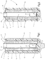
- FIG. 1 and 4 in the latter in a sectional view, shown as a whole embodiment of the filter device according to the invention comprises a filter housing 1, which is provided for receiving a filter element 3, the in Fig. 2 and 3 , in the latter in section, is shown separately.
- the filter housing 1 made of plastic or a metallic material has the shape of a hollow cylinder closed at the bottom 5, which is open at the opposite, upper end 7. The insertable from the open end 7 into the filter housing 1 filter element 3, which is designed in the manner of a so-called.
- Filter cartridge has a filter material 9 in the form of a pleated Filter mat, which in the usual manner in such filter cartridges a fluid-permeable support tube 11, preferably made of plastic, surrounds, within which an inner filter cavity 13 is located.
- a fluid-permeable support tube 11 preferably made of plastic
- a second, outer, fluid-permeable support tube 15 At the bottom in the drawing, the filter material 9 is enclosed by a closed end cap 17.
- an end cap 19 At the other end of the filter material 9 is an end cap 19, at which the connection is made to an associated filter head, which is not shown and via which the supply of a fluid to be cleaned and the discharge of purified fluid takes place.
- the end cap 19, which is injection molded in one piece as the closed end cap 17 of a plastic material, has a connection piece 21 for the fluid connection to the inner filter cavity 13, to which an O-ring 23 is located for sealing the filter head.
- the end cap 19 in outline is not completely circular, but has recesses extending inward in the radial direction.
- annular gaps 25 are formed between the end cap 19 and the edge 27 of a casing which surrounds the end cap 19.
- This has the shape of a pot 29, which extends from its open edge 27, forming a circular cylinder, to a closed bottom part 31.
- the closed at the bottom part 31 pot 29 which forms a sheath which completely surrounds the filter element 3 to the upper end cap 19, is made of a compressible material.
- the pot 29 forms an effective compensating device by compressing the material of the pot 29 by increasing the volume of the fluid space in the filter element 3 takes place, the pressure increases counteracts or even pressure peaks.
- materials for the pot 29, which are suitable for compression against the inner wall of the housing 1 are preferably porous compressible materials with closed pores in question.
- serving as a sheath pot 29 is formed of a sponge rubber, preferably an ethylene-propylene-diene rubber (EPDM).
- EPDM ethylene-propylene-diene rubber
- the pot 29 is a one-piece component with a bottom portion 31 axially inwardly projecting hump 33 as centering for the closed lower end cap 17. From the latter, starting a stabilizer 35 extends into the inner filter cavity thirteenth
- Pot 29 is formed, remain when removing a filter element to be replaced 3 residual fluids and deposited substances within the pot 29, which thus serves as a receptacle for contaminated media. Pollution of the housing during changes is avoided. Also in the filtration process contacting of the wall of the housing 1 by operating fluids is prevented by the pot 29 is pressed by the prevailing in the filtration process system pressure to the inner wall of the housing 1.
Landscapes
- Chemical & Material Sciences (AREA)
- Chemical Kinetics & Catalysis (AREA)
- Filtration Of Liquid (AREA)
- Filtering Of Dispersed Particles In Gases (AREA)
Description
- Die Erfindung betrifft eine Filtervorrichtung mit den Merkmalen im Oberbegriff von Anspruch 1.
- Filtervorrichtungen mit mindestens einem in einem Gehäuse aufnehmbaren Filterelement, das mit einem entsprechenden Systemdruck oder Fluidbetriebsdruck durchströmbar ist, sind handelsüblich und finden beispielsweise bei Hydraulikanlagen in von Hydrauliköl durchströmten Systemzweigen verbreitete Anwendung. Zur druckstabilen Ausbildung des jeweiligen Filterelements ist in der Regel vorgesehen, dass ein Stützrohr, vorzugsweise aus Kunststoffmaterial, vorgesehen ist, welches mit Perforationen versehen die Abstützung des eingesetzten Filtermaterials entgegen der vorgegebenen Durchströmungsrichtung des Fluids vornimmt. Bei einer aus
DE 10 2008 004 344 A1 bekannten Filtervorrichtung ist das Filtermaterial als plissierte Filtermatte um ein fluiddurchlässiges Stützrohr gelegt, und das jeweilige Filterelement ist mit Endkappen versehen. - Im Betrieb einer Filtervorrichtung, insbesondere in Hydrauliksystemen, kann es je nach Anwendung zu stärkeren Druckpulsationen oder Druckspitzen kommen. Folglich kann der lokal am jeweiligen Filterelement herrschende Fluiddruck vom vorgegebenen Fluidbetriebsdruck derart abweichen, insbesondere diesen derart übersteigen, dass es zu Schädigungen am jeweiligen Filterelement, insbesondere dem eingesetzten Filtermaterial, kommen kann. Derartige Druckpulsationen treten insbesondere in Hydrauliksystemen mit schnell schließenden Ventilen oder mit Kolbenpumpen auf. Bei solchen Druckpulsationen können mitunter die für das jeweilige Filterelement geforderte Schmutzaufnahme und die entsprechend eingestellte Feinheit beeinträchtigt werden. Gegebenenfalls kann es zu einer Zerstörung des Filtermaterials kommen.
- Um diesen Gefährdungen zu begegnen, ist es Stand der Technik, vergl. das Dokument
US 2009/0218295 A1 , mittels einer nachgiebigen Ausgleichseinrichtung auftretende Druckschwankungen zu glätten. Bei dieser bekannten Lösung ermöglicht die Nachgiebigkeit der Ausgleichseinrichtung Änderungen des Volumens, das sich innerhalb eines ein betreffendes Filterelement aufnehmenden Filtergehäuses befindet. Die bekannte Lösung ist unter anderem zumindest insofern nicht zufriedenstellend, als für die Ausgleichseinrichtung innerhalb des Filtergehäuses ein verhältnismäßig großer Bauraum erforderlich ist, so dass keine kompakte Bauweise verwirklichbar ist. - Die
DE 10 2010 061 222 A1 beschreibt eine Filtervorrichtung mit mindestens einem von einem abzureinigenden Fluid mit vorgebbarem Fluidbetriebsdruck durchströmbaren, in einem Gehäuse aufnehmbaren Filterelement, wobei der am jeweiligen Filterelement herrschende Fluiddruck das jeweilige Filterelement, insbesondere dessen Filtermaterial, schädigende Druckspitzen oder generelle Druckerhöhungen aufweisen kann, die mittels einer auf das jeweilige Filterelement direkt einwirkenden Ausgleichseinrichtung reduzierbar und/oder glättbar sind, die mindestens ein nachgiebiges Ausgleichselement aufweist, das entsprechend einer Druckspitze oder Druckerhöhung eine Vergrößerung des Volumens des Fluidraums des Gehäuses ermöglicht, wobei das nachgiebige Ausgleichselement zwischen der Außenseite des Filtermaterials des Filterelements und der benachbarten Innenwand des Gehäuses angeordnet ist, wobei das nachgiebige Ausgleichselement durch eine zumindest teilweise Ummantelung der Außenseite des jeweiligen, im Gehäuse befindlichen Filterelements gebildet ist, wobei die Ummantelung die Form eines kreiszylindrischen Topfes besitzt. - Weitere Filtervorrichtungen gehen aus der
WO 2013/178352 A1 , derWO 2013/178336 A1 , derEP 1 360 983 A1 , derWO 2010/139706 A1 , derUS 2005/0161394 A1 , derDE 2 121 533 , derDE 10 2006 003 551 A1 , derEP 2 228 113 A1 , derWO 2012/007337 A1 , derUS 2012/0248024 A1 und derDE 29 15 730 A1 hervor. DieDE 10 2009 009 899 A1 betrifft ein Kraftfahrzeug mit einer eine selektive katalytische Reduktion ermöglichenden Abgasanlage. - Ausgehend von diesem Stand der Technik stellt sich die Erfindung die Aufgabe, eine Filtervorrichtung zur Verfügung zu stellen, die den zu stellenden Anforderungen besser gerecht wird, insbesondere eine kompakte Bauweise ermöglicht.
- Erfindungsgemäß ist diese Aufgabe durch eine Filtervorrichtung gelöst, die die Merkmale des Patentanspruchs 1 in seiner Gesamtheit aufweist.
- Gemäß dem kennzeichnenden Teil des Anspruchs 1 bestehen wesentliche Besonderheiten der Erfindung darin, dass der Topf innenseitig an einem fluiddurchlässigen Stützrohr anliegt und dass das Stützrohr seinerseits an der Außenseite des Filtermaterials des betreffenden Filterelements als dessen äußeres Stützrohr anliegt. Bei einer Druckerhöhung oder Druckspitze im inneren Fluidraum des Filterelements erfolgt eine Vergrößerung des Volumens durch Komprimieren der Ummantelung durch den am äußeren Stützrohr anstehenden Druck.
- Es ist ferner vorgesehen, dass das nachgiebige Ausgleichselement zwischen der Außenseite des Filtermaterials des Filterelements und der benachbarten Innenwand des Gehäuses angeordnet ist. Im Gegensatz zu der genannten, bekannten Lösung, bei der die Ausgangseinrichtung sich als axiale Verlängerung an ein Ende des Filterelements anschließt, ermöglicht es die Erfindung, die Filtervorrichtung derart auszubilden, dass die Baulänge des Gehäuses die Baulänge des Filterelements nicht wesentlich übersteigt.
- Mit besonderem Vorteil kann eine derartige Ummantelung durch einen Körper vorgegebener Kompressibilität gebildet sein, wobei es sich vorzugsweise um einen porösen, geschlossene Poren aufweisenden Stoff, beispielsweise einen Schaumstoff, handeln kann. Bei einer besonders vorteilhaften Ausführungsform ist eine Ummantelung aus Moosgummi, vorzugsweise einem Ethylen-Propylen-Dien-Kautschuk (EPDM), vorgesehen. Eine derartige Ummantelung bietet ein besonders günstiges Verhältnis zwischen unbelasteter Volumengröße und komprimierter Volumengröße.
- Bei besonders vorteilhaften Ausführungsbeispielen, mit einem Filterelement, das ein einen hohlzylindrischen, inneren Filterhohlraum umgebendes Filtermaterial aufweist, das endseits von einer den Eingang und den Ausgang des Fluidraums bildenden Endkappe eingefasst ist, ist die Anordnung mit besonderem Vorteil so getroffen, dass die Ummantelung, die Endkappe zumindest teilweise freilassend, das Filterelement vollständig umfasst. Bei einem Mindestmaß an für die Ausgleichseinrichtung erforderlichem zusätzlichem Bauraum ist dadurch eine optimale Ausgleichswirkung erzielbar.
- Bei besonders vorteilhaften Ausführungsbeispielen ist die Anordnung so getroffen, dass die Außenseite des Topfes der Ummantelung an der Innenseite des Gehäuses anliegt, beim Zustand fehlenden Fluidbetriebsdrucks jedoch als Einheit zusammen mit dem Filterelement aus dem Gehäuse herausnehmbar ist. Dadurch, dass der Topf zusammen mit dem Filterelement für Auswechselvorgänge aus dem Gehäuse herausnehmbar ist, ergibt sich der zusätzliche bedeutsame Vorteil, dass Filterelementwechsel bequem, sauber und umweltschonend durchgeführt werden können, weil beim Herausnehmen des Filterelements Fluidrückstände und Abscheidungen mit dem Topf der Ummantelung herausgenommen werden und dadurch weder das Gehäuse noch die Umwelt bei der Handhabung verbrauchter Filterelemente gefährdet werden.
- Ein weiterer, besonderer Vorteil der Erfindung besteht darin, dass die Ausgleichseinrichtung außer der Dämpfung von Druckpulsationen einen Gefrierschutz für die Filtervorrichtung bildet. Dies ist bedeutsam, wenn es sich um Fluide in Form gefrierbarer Substanzen handelt. Dies ist beispielsweise bei in der Fahrzeugtechnik eingesetzten Systemen der Fall, die in der Fachsprache als Adblue-Systeme bezeichnet sind. Bei diesen Systemen werden für die Abgasbehandlung bei Verbrennungsmotoren wässrige Harnstofflösungen über eine Zuführeinrichtung von einem Vorratstank dosiert dem Abgasstrom zugeführt, wobei aus dem Harnstoff durch Hydrolyse Ammoniak gewonnen wird. Dieses wirkt im Abgasstrom als selektives Reduktionsmittel. Um den Wirkungsgrad der Reduktion zu optimieren, wird die wässrige Harnstofflösung dem Abgasstrom mittels einer durch ein Steuergerät lastabhängig gesteuerten Pumpe dosiert zugeführt. Bei durch eine Kolbenpumpe zugeführter Harnstofflösung, die systembedingt mit Druckpulsationen behaftet ist, wirkt die Ausgleichseinrichtung zum einen glättend. Zum anderen verhindert die Ausgleichseinrichtung, als Gefrierschutz, dass es bei Frosttemperaturen und dadurch bedingtem Gefrieren der wässrigen Harnstofflösung aufgrund der Volumenvergrößerung beim Gefriervorgang zu einem Bersten von Wandungen der Filtervorrichtung kommen kann oder insbesondere eine Schädigung oder Zerstörung eines betreffenden Filterelements eintritt, weil die Ausgleichseinrichtung eine beim Gefrieren erfolgende Volumenvergrößerung kompensiert.
- Gemäß dem Patentanspruch 7 ist Gegenstand der Erfindung auch ein Filterelement, das insbesondere zur Benutzung bei einer Filtervorrichtung nach einem der Patentansprüche 1 bis 6 vorgesehen ist.
- Nachstehend ist die Erfindung anhand eines in der Zeichnung dargestellten Ausführungsbeispiels im Einzelnen erläutert. Es zeigen:
- Fig. 1
- eine perspektivische Schrägansicht eines Ausführungsbeispiels der erfindungsgemäßen Filtervorrichtung, gesehen auf die Endkappe eines zugehörigen Filterelements;
- Fig. 2
- eine perspektivische Schrägansicht lediglich des Filterelements des Ausführungsbeispiels, wiederum gesehen auf dessen Endkappe und mit teilweise aufgeschnittener Ummantelung, so dass ein Teil der Außenseite des Filtermaterials des Filterelements sichtbar ist;
- Fig. 3
- einen Längsschnitt des in
Fig. 2 gezeigten Filterelements; - Fig. 4
- einen Längsschnitt des Ausführungsbeispiels der Filtervorrichtung, wobei das Filterelement von
Fig. 2 und3 im zugehörigen Filtergehäuse aufgenommen ist; und - Fig. 5
- einen gegenüber
Fig. 3 vergrößert gezeichneten Teillängsschnitt lediglich des einer Endkappe benachbarten Bereichs des Filterelements. - Das in
Fig. 1 und4 , in letzterer in Schnittdarstellung, als Ganzes gezeigte Ausführungsbeispiel der erfindungsgemäßen Filtervorrichtung weist ein Filtergehäuse 1 auf, das zur Aufnahme eines Filterelements 3 vorgesehen ist, das inFig. 2 und3 , in letzterer in Schnittdarstellung, gesondert gezeigt ist. Das Filtergehäuse 1 aus Kunststoff oder einem metallischen Werkstoff hat die Form eines am Boden 5 geschlossenen Hohlzylinders, der am gegenüberliegenden, oberen Ende 7 offen ist. Das vom offenen Ende 7 her in das Filtergehäuse 1 einsetzbare Filterelement 3, das in der Art einer sog. Filterpatrone ausgebildet ist, weist ein Filtermaterial 9 in Form einer plissierten Filtermatte auf, die in der bei derartigen Filterpatronen üblichen Weise ein fluiddurchlässiges Stützrohr 11, vorzugsweise aus Kunststoff, umgibt, innerhalb dessen sich ein innerer Filterhohlraum 13 befindet. An der Außenseite des Filtermaterials 9 befindet sich ein zweites, äußeres, fluiddurchlässiges Stützrohr 15. An dem in der Zeichnung unteren Ende ist das Filtermaterial 9 von einer geschlossenen Endkappe 17 eingefasst. Am anderen Ende des Filtermaterials 9 befindet sich eine Endkappe 19, an der der Anschluss an einem zugeordneten Filterkopf erfolgt, der nicht gezeigt ist und über den die Zufuhr eines abzureinigenden Fluids sowie die Abgabe abgereinigten Fluids erfolgt. Die Endkappe 19, die wie die geschlossene Endkappe 17 aus einem Kunststoffwerkstoff einstückig spritzgeformt ist, weist für die Fluidverbindung zum inneren Filterhohlraum 13 einen Anschlussstutzen 21 auf, an dem sich für die Abdichtung am Filterkopf ein O-Ring 23 befindet. - Wie am besten aus
Fig. 1 und 2 zu ersehen ist, ist die Endkappe 19 im Umriss nicht vollständig kreisrund, sondern weist Ausnehmungen auf, die sich in Radialrichtung einwärts erstrecken. Dadurch sind am Umfang der Endkappe 19 Ringspalte 25 zwischen der Endkappe 19 und dem Rand 27 einer die Endkappe 19 umfassenden Ummantelung gebildet. Diese hat die Form eines Topfes 29, der sich von seinem offenen Rand 27, einen Kreiszylinder bildend, zu einem geschlossenen Bodenteil 31 erstreckt. Bei der Funktionsposition, bei welcher der Topf 29 im Filtergehäuse 1 aufgenommen ist, befindet sich, sieheFig. 4 , das Bodenteil 31 des Topfes 29 am Boden 5 des Gehäuses 1. Die Spalte 25 bilden, wie der Stutzen 21, vom nicht gezeigten Filterkopf her die Fluidverbindung zum inneren Fluidraum des Filterelements 3, wobei die Richtung der Durchströmung beim Filtrationsvorgang so vorgesehen sein kann, dass das abzureinigende Fluid über die Spalte 25 einströmt, sich entlang des äußeren Stützrohres 15 verteilt und nach Durchströmen des Filtermaterials 9 über den Stutzen 21 der Endkappe 19 austritt. - Der am Bodenteil 31 geschlossene Topf 29, der eine Ummantelung bildet, die das Filterelement 3 bis auf die obere Endkappe 19 vollständig umgibt, ist aus einem kompressiblen Material gebildet. In der Funktionsposition, wobei das Filterelement 3 im Gehäuse 1 derart aufgenommen ist, siehe
Fig. 4 , dass der die Ummantelung bildende Topf 29 mit glattflächiger Außenseite an der ebenfalls glattflächigen Innenwand des Gehäuses 1 anliegt, bildet der Topf 29 aufgrund seiner Nachgiebigkeit eine wirksame Ausgleichseinrichtung, indem durch druckbedingtes Komprimieren des Werkstoffs des Topfes 29 eine Vergrößerung des Volumens des Fluidraums im Filterelement 3 stattfindet, die Druckerhöhungen entgegenwirkt oder Druckspitzen glättet. Als Werkstoffe für den Topf 29, die für ein Zusammendrücken gegen die Innenwand des Gehäuses 1 geeignet sind, kommen vorzugsweise poröse kompressible Materialien mit geschlossenen Poren in Frage. Beim vorliegenden Ausführungsbeispiel ist der als Ummantelung dienende Topf 29 aus einem Moosgummi, vorzugsweise einem Ethylen-Propylen-Dien-Kautschuk (EPDM) ausgebildet. WieFig. 3 und 4 zeigen, ist der Topf 29 ein einteiliges Bauteil mit einem vom Bodenteil 31 axial nach innen vorspringenden Höcker 33 als Zentrierstück für die geschlossene untere Endkappe 17. Von letzterer ausgehend erstreckt sich ein Stabilisierkörper 35 in den inneren Filterhohlraum 13. - Wie bereits erwähnt, sind Außenseite des die Ummantelung bildenden Topfes 29 und Innenwand des Filtergehäuses 1 glattflächig. Die Dimensionierung von Filterelement 3 und Gehäuse 1 ist so bemessen, dass das Filterelement 3 vom offenen Ende 7 des Gehäuses 1 her in dieses einsetzbar ist. Um leichtes Einsetzen und Herausnehmen zu ermöglichen, sind in der Außenseite des Topfes 29, als Unterbrechung der ansonsten glatten Außenfläche, drei in Winkelabständen von 120° zueinander versetzte, vertiefte Längsrillen 39 ausgebildet, von denen lediglich eine in
Fig. 2 sichtbar ist. Diese Längsrillen 39 ermöglichen einen entsprechenden Druckausgleich beim Einschieben des Filterelements 3 in das Gehäuse 1 und beim Herausnehmen des Filterelements 3 aus dem Gehäuse 1 für Filterelementwechsel. Dank der Ummantelung, die durch einen am Bodenteil 31 geschlossenen Topf 29 gebildet ist, verbleiben beim Herausnehmen eines auszuwechselnden Filterelements 3 Restfluide und abgeschiedene Substanzen innerhalb des Topfes 29, der somit als Auffangbehälter für verschmutzte Medien dient. Eine Verschmutzung des Gehäuses bei Wechselvorgängen ist dadurch vermieden. Auch beim Filtrationsvorgang ist eine Kontaktierung der Wand des Gehäuses 1 durch Betriebsfluide dadurch verhindert, dass der Topf 29 durch den beim Filtrationsvorgang herrschenden Systemdruck an die Innenwand des Gehäuses 1 angedrückt wird.
Claims (9)
- Filtervorrichtung mit mindestens einem von einem abzureinigenden Fluid mit vorgebbarem Fluidbetriebsdruck durchströmbaren, in einem Gehäuse (1) aufnehmbaren Filterelement (3), wobei der am jeweiligen Filterelement (3) herrschende Fluiddruck das jeweilige Filterelement (3), insbesondere dessen Filtermaterial (9), schädigende Druckspitzen oder generelle Druckerhöhungen aufweisen kann, die mittels einer auf das jeweilige Filterelement (3) direkt einwirkenden Ausgleichseinrichtung reduzierbar und/oder glättbar sind, die mindestens ein nachgiebiges Ausgleichselement (29) aufweist, das entsprechend einer Druckspitze oder Druckerhöhung eine Vergrößerung des Volumens des Fluidraums des Gehäuses (1) ermöglicht, wobei das nachgiebige Ausgleichselement (29) zwischen der Außenseite des Filtermaterials (9) des Filterelements (3) und der benachbarten Innenwand des Gehäuses (1) angeordnet ist, wobei das nachgiebige Ausgleichselement durch eine zumindest teilweise Ummantelung (29) der Außenseite des jeweiligen, im Gehäuse (1) befindlichen Filterelements (3) gebildet ist, wobei die Ummantelung die Form eines kreiszylindrischen Topfes (29) besitzt, dadurch gekennzeichnet, dass der Topf (29) innenseitig an einem fluiddurchlässigen Stützrohr (15) anliegt und dass das Stützrohr (15) seinerseits an der Außenseite des Filtermaterials (9) des betreffenden Filterelements (3) als dessen äußeres Stützrohr (15) anliegt.
- Filtervorrichtung nach Anspruch 1, dadurch gekennzeichnet, dass eine Ummantelung (29) durch einen Körper vorgegebener Kompressibilität gebildet ist.
- Filtervorrichtung nach einem der vorstehenden Ansprüche, dadurch gekennzeichnet, dass eine Ummantelung (29) aus einem porösen, geschlossene Poren aufweisenden Stoff, wie einem Schaumstoff, vorgesehen ist.
- Filtervorrichtung nach einem der vorstehenden Ansprüche, dadurch gekennzeichnet, dass eine Ummantelung (29) aus Moosgummi, vorzugsweise einem Ethylen-Propylen-Dien-Kautschuk (EPDM), vorgesehen ist.
- Filtervorrichtung nach einem der vorstehenden Ansprüche, dadurch gekennzeichnet, dass ein Filterelement (3) mit einem einen hohlzylindrischen, inneren Filterhohlraum umgebenden Filtermaterial (9) vorgesehen ist, das endseits von einer den Eingang (25) und den Ausgang (21) des Fluidraums bildenden Endkappe (19) eingefasst ist, und dass die Ummantelung (29), die Endkappe (19) zumindest teilweise freilassend, das Filterelement (3) vollständig umfasst.
- Filtervorrichtung nach einem der vorstehenden Ansprüche, dadurch gekennzeichnet, dass die Außenseite des Topfes (29) der Ummantelung an der Innenseite des Gehäuses (1) anliegt, beim Zustand fehlenden Fluidbetriebsdrucks jedoch als Einheit zusammen mit dem Filterelement (3) aus dem Gehäuse (1) herausnehmbar ist.
- Filterelement, insbesondere zur Benutzung bei einer Filtervorrichtung nach einem der Ansprüche 1 bis 6, mit einer die Außenseite des zugehörigen Filterelements (3) zumindest teilweise umgebenden Ummantelung (29) aus einem kompressiblen Material, wobei die Ummantelung die Form eines kreiszylindrischen Topfes (29) besitzt, dadurch gekennzeichnet, dass der Topf (29) innenseitig an einem fluiddurchlässigen Stützrohr (15) anliegt und dass das Stützrohr (15) seinerseits an der Außenseite eines Filtermaterials (9) des betreffenden Filterelements (3) als dessen äußeres Stützrohr (15) anliegt.
- Filterelement nach Anspruch 7, dadurch gekennzeichnet, dass eine Ummantelung (29) aus einem porösen, geschlossene Poren aufweisenden Stoff, wie einem Schaumstoff, vorzugsweise aus Moosgummi, vorgesehen ist.
- Filterelement nach Anspruch 7 oder 8, dadurch gekennzeichnet, dass es ein einen hohlzylindrischen, inneren Filterhohlraum (13) umgebendes Filtermaterial (9) aufweist, das endseitig von einer den Eingang (25) und den Ausgang (21) des Fluidraums bildenden Endkappe (19) eingefasst ist, und dass die Ummantelung (29), die Endkappe (19) zumindest teilweise freilassend, das Filterelement (3) vollständig umfasst.
Applications Claiming Priority (2)
| Application Number | Priority Date | Filing Date | Title |
|---|---|---|---|
| DE102012020431.0A DE102012020431A1 (de) | 2012-10-18 | 2012-10-18 | Filtervorrichtung |
| PCT/EP2013/003069 WO2014060084A1 (de) | 2012-10-18 | 2013-10-11 | Filtervorrichtung |
Publications (2)
| Publication Number | Publication Date |
|---|---|
| EP2908923A1 EP2908923A1 (de) | 2015-08-26 |
| EP2908923B1 true EP2908923B1 (de) | 2019-08-07 |
Family
ID=49474365
Family Applications (1)
| Application Number | Title | Priority Date | Filing Date |
|---|---|---|---|
| EP13780066.0A Active EP2908923B1 (de) | 2012-10-18 | 2013-10-11 | Filtervorrichtung |
Country Status (4)
| Country | Link |
|---|---|
| US (1) | US10143945B2 (de) |
| EP (1) | EP2908923B1 (de) |
| DE (1) | DE102012020431A1 (de) |
| WO (1) | WO2014060084A1 (de) |
Families Citing this family (6)
| Publication number | Priority date | Publication date | Assignee | Title |
|---|---|---|---|---|
| US9895633B2 (en) * | 2015-01-06 | 2018-02-20 | A.L. Filter Co., Ltd. | Freezing resistant liquid filter |
| DE102015010562A1 (de) | 2015-08-12 | 2017-02-16 | Hydac Filtertechnik Gmbh | Filtervorrichtung nebst Filterelement |
| DE102015010532A1 (de) | 2015-08-12 | 2017-02-16 | Hydac Filtertechnik Gmbh | Filtervorrichtung nebst Filterelement |
| DE102015010533A1 (de) | 2015-08-12 | 2017-02-16 | Hydac Filtertechnik Gmbh | Filtervorrichtung nebst Filterelement |
| US10100697B2 (en) | 2016-04-11 | 2018-10-16 | Tenneco Automotive Operating Company Inc. | Fluid delivery system for exhaust aftertreatment system |
| DE202024103109U1 (de) * | 2024-06-11 | 2024-07-01 | A.L. Filter Ead | Vorrichtung zur Filtration einer Harnstoff-Wasser-Lösung |
Citations (1)
| Publication number | Priority date | Publication date | Assignee | Title |
|---|---|---|---|---|
| DE2915730A1 (de) * | 1979-04-19 | 1980-10-30 | Kronsbein Dirk Gustav | Patronenfilter |
Family Cites Families (19)
| Publication number | Priority date | Publication date | Assignee | Title |
|---|---|---|---|---|
| US1059370A (en) * | 1912-05-13 | 1913-04-22 | John N Johnson | Means for relieving the walls of receptacles from undue internal pressure. |
| DE2121533A1 (de) * | 1971-05-03 | 1972-11-23 | Fa. Ing. Josef Wagner, 7991 Friedrichshafen-Fischbach | Hochdruck-Filter, insbesondere für Farbspritzanlagen |
| DE10220662B4 (de) * | 2002-05-10 | 2005-08-11 | Hydraulik-Ring Gmbh | Filterpatrone für flüssige, einfriergefährdete Medien, insbesondere für den Einsatz bei Brennstoffzellenfahrzeugen und bei Verbrennungskraftmaschinen, vorzugsweise Dieselmotoren |
| DE10220672B4 (de) | 2002-05-10 | 2008-01-03 | Hydraulik-Ring Gmbh | Filtereinheit für einfrierende Flüssigkeiten |
| US20050161394A1 (en) * | 2002-11-20 | 2005-07-28 | Karl Fritze | Freeze resistant water filter |
| DE102006003551B4 (de) | 2005-03-01 | 2008-09-11 | Mann+Hummel Gmbh | Filtereinrichtung zur Flüssigkeitsfilterung |
| KR100873294B1 (ko) * | 2007-06-14 | 2008-12-11 | 웅진코웨이주식회사 | 필터 조립체 |
| DE102008004344A1 (de) | 2008-01-15 | 2009-08-06 | Hydac Filtertechnik Gmbh | Filter |
| US8114299B2 (en) | 2008-02-28 | 2012-02-14 | Cummins Filtration Ip, Inc. | Filter with flow surge protection and method of protecting filter from flow surge |
| DE102009009899A1 (de) | 2009-02-20 | 2010-08-26 | Bayerische Motoren Werke Aktiengesellschaft | Kraftfahrzeug mit einer eine selektive katalytische Reduktion ermöglichenden Abgasanlage |
| DE102009011568B4 (de) | 2009-03-06 | 2010-12-23 | Mann + Hummel Gmbh | Filtereinrichtung für ein Kraftfahrzeug |
| JP5302087B2 (ja) * | 2009-04-27 | 2013-10-02 | スリーエム イノベイティブ プロパティズ カンパニー | 筒形フィルタ |
| DE102009023951B3 (de) * | 2009-06-04 | 2011-01-05 | Mann + Hummel Gmbh | Filtereinrichtung zur Flüssigkeitsfiltrierung |
| DE102010027069B3 (de) | 2010-07-13 | 2012-02-23 | Mann + Hummel Gmbh | Harnstoff-Wasser-Lösung-Filtersystem |
| DE102010061222B4 (de) * | 2010-12-14 | 2015-05-07 | Cummins Ltd. | SCR-Abgasnachbehandlungseinrichtung |
| DE102011013186B4 (de) * | 2011-03-05 | 2013-01-03 | Hydac Filtertechnik Gmbh | Filtervorrichtung |
| US20120248024A1 (en) | 2011-03-29 | 2012-10-04 | Kuss Filtration, Inc. | Filter with Inner-Sealed Pulsation Dampener |
| DE102012010981A1 (de) | 2012-06-02 | 2013-12-05 | Hydac Filtertechnik Gmbh | System zur Abgasnachbehandlung bei Verbrennungsmotoren |
| DE102012010979A1 (de) | 2012-06-02 | 2013-12-05 | Hydac Electronic Gmbh | System zur Abgasnachbehandlung bei Verbrennungsmotoren |
-
2012
- 2012-10-18 DE DE102012020431.0A patent/DE102012020431A1/de not_active Withdrawn
-
2013
- 2013-10-11 EP EP13780066.0A patent/EP2908923B1/de active Active
- 2013-10-11 WO PCT/EP2013/003069 patent/WO2014060084A1/de not_active Ceased
- 2013-10-11 US US14/433,425 patent/US10143945B2/en active Active
Patent Citations (1)
| Publication number | Priority date | Publication date | Assignee | Title |
|---|---|---|---|---|
| DE2915730A1 (de) * | 1979-04-19 | 1980-10-30 | Kronsbein Dirk Gustav | Patronenfilter |
Also Published As
| Publication number | Publication date |
|---|---|
| EP2908923A1 (de) | 2015-08-26 |
| DE102012020431A1 (de) | 2014-04-24 |
| US20150258473A1 (en) | 2015-09-17 |
| US10143945B2 (en) | 2018-12-04 |
| WO2014060084A1 (de) | 2014-04-24 |
Similar Documents
| Publication | Publication Date | Title |
|---|---|---|
| EP2908923B1 (de) | Filtervorrichtung | |
| DE102012003121B4 (de) | Filterkartusche für eine Reduktionsmittelfördervorrichtung | |
| EP3854470B1 (de) | Filtereinrichtung und rundfilterelement, insbesondere zur gasfiltration | |
| EP3096859B1 (de) | Filterelement | |
| EP3017854B1 (de) | Filter zur filtrierung von fluid | |
| EP3620220B1 (de) | Filtervorrichtung | |
| DE102016001025A1 (de) | Filterelement eines Flüssigkeitsfilters, Flüssigkeitsfilter und Filtergehäuse | |
| EP2865433A2 (de) | Filterelement und Filtersystem für ein Flüssigmedium, insbesondere Dieselkraftstoff | |
| EP3334513B1 (de) | Filtervorrichtung nebst filterelement | |
| EP2845636A1 (de) | Filterelement und Verfahren zur Herstellung eines Filterelements | |
| EP2854987B1 (de) | System zur abgasnachbehandlung bei verbrennungsmotoren sowie zur pulsationsdämpfung und/oder volumenstromglättung von fluiden | |
| EP1671692B1 (de) | Flüssigkeitswechselfilter mit Rücklaufsperrventil | |
| EP3334514B1 (de) | Filtervorrichtung | |
| WO2019110361A1 (de) | Rundfilterelement eines filters für harnstoff-wasser-lösung und filter | |
| DE102012003156B4 (de) | Filterkartusche für eine gefriergefährdete Flüssigkeit | |
| EP3334515B1 (de) | Filtervorrichtung | |
| DE102017011437A1 (de) | Filter einer Filtervorrichtung zur Filtrierung von Fluid und Filterkopf einer Filtervorrichtung | |
| DE202008004290U1 (de) | Filterverschluss-System | |
| DE102013004865B4 (de) | Filtereinrichtung mit einem ringförmigen Filterelement | |
| DE112017005430B4 (de) | Flüssigkeitsreinigungselement, Flüssigkeitsreinigungssystem und Verfahren zur Herstellung eines Flüssigkeitsreinigungselements | |
| DE102009026764A1 (de) | Schwalltopf sowie Abgasreinigungseinrichtung | |
| DE102010039053A1 (de) | Filtereinrichtung sowie Ansaugvorrichtung | |
| DE102022209308A1 (de) | Filterelement | |
| DE102017210231A1 (de) | Filtereinrichtung und Fördermodul für ein Fluid sowie Betriebsverfahren hierzu | |
| DE102017201140A1 (de) | Filteranordnung für einen Reduktionsmittel-Vorratstank oder eine Funktionseinheit |
Legal Events
| Date | Code | Title | Description |
|---|---|---|---|
| PUAI | Public reference made under article 153(3) epc to a published international application that has entered the european phase |
Free format text: ORIGINAL CODE: 0009012 |
|
| 17P | Request for examination filed |
Effective date: 20150317 |
|
| AK | Designated contracting states |
Kind code of ref document: A1 Designated state(s): AL AT BE BG CH CY CZ DE DK EE ES FI FR GB GR HR HU IE IS IT LI LT LU LV MC MK MT NL NO PL PT RO RS SE SI SK SM TR |
|
| AX | Request for extension of the european patent |
Extension state: BA ME |
|
| DAX | Request for extension of the european patent (deleted) | ||
| STAA | Information on the status of an ep patent application or granted ep patent |
Free format text: STATUS: EXAMINATION IS IN PROGRESS |
|
| 17Q | First examination report despatched |
Effective date: 20170807 |
|
| GRAP | Despatch of communication of intention to grant a patent |
Free format text: ORIGINAL CODE: EPIDOSNIGR1 |
|
| STAA | Information on the status of an ep patent application or granted ep patent |
Free format text: STATUS: GRANT OF PATENT IS INTENDED |
|
| INTG | Intention to grant announced |
Effective date: 20190409 |
|
| GRAS | Grant fee paid |
Free format text: ORIGINAL CODE: EPIDOSNIGR3 |
|
| GRAA | (expected) grant |
Free format text: ORIGINAL CODE: 0009210 |
|
| STAA | Information on the status of an ep patent application or granted ep patent |
Free format text: STATUS: THE PATENT HAS BEEN GRANTED |
|
| AK | Designated contracting states |
Kind code of ref document: B1 Designated state(s): AL AT BE BG CH CY CZ DE DK EE ES FI FR GB GR HR HU IE IS IT LI LT LU LV MC MK MT NL NO PL PT RO RS SE SI SK SM TR |
|
| REG | Reference to a national code |
Ref country code: GB Ref legal event code: FG4D Free format text: NOT ENGLISH |
|
| REG | Reference to a national code |
Ref country code: CH Ref legal event code: EP Ref country code: AT Ref legal event code: REF Ref document number: 1162946 Country of ref document: AT Kind code of ref document: T Effective date: 20190815 |
|
| REG | Reference to a national code |
Ref country code: DE Ref legal event code: R096 Ref document number: 502013013331 Country of ref document: DE |
|
| REG | Reference to a national code |
Ref country code: IE Ref legal event code: FG4D Free format text: LANGUAGE OF EP DOCUMENT: GERMAN |
|
| REG | Reference to a national code |
Ref country code: NL Ref legal event code: MP Effective date: 20190807 |
|
| REG | Reference to a national code |
Ref country code: LT Ref legal event code: MG4D |
|
| PG25 | Lapsed in a contracting state [announced via postgrant information from national office to epo] |
Ref country code: NL Free format text: LAPSE BECAUSE OF FAILURE TO SUBMIT A TRANSLATION OF THE DESCRIPTION OR TO PAY THE FEE WITHIN THE PRESCRIBED TIME-LIMIT Effective date: 20190807 Ref country code: SE Free format text: LAPSE BECAUSE OF FAILURE TO SUBMIT A TRANSLATION OF THE DESCRIPTION OR TO PAY THE FEE WITHIN THE PRESCRIBED TIME-LIMIT Effective date: 20190807 Ref country code: BG Free format text: LAPSE BECAUSE OF FAILURE TO SUBMIT A TRANSLATION OF THE DESCRIPTION OR TO PAY THE FEE WITHIN THE PRESCRIBED TIME-LIMIT Effective date: 20191107 Ref country code: NO Free format text: LAPSE BECAUSE OF FAILURE TO SUBMIT A TRANSLATION OF THE DESCRIPTION OR TO PAY THE FEE WITHIN THE PRESCRIBED TIME-LIMIT Effective date: 20191107 Ref country code: LT Free format text: LAPSE BECAUSE OF FAILURE TO SUBMIT A TRANSLATION OF THE DESCRIPTION OR TO PAY THE FEE WITHIN THE PRESCRIBED TIME-LIMIT Effective date: 20190807 Ref country code: FI Free format text: LAPSE BECAUSE OF FAILURE TO SUBMIT A TRANSLATION OF THE DESCRIPTION OR TO PAY THE FEE WITHIN THE PRESCRIBED TIME-LIMIT Effective date: 20190807 Ref country code: PT Free format text: LAPSE BECAUSE OF FAILURE TO SUBMIT A TRANSLATION OF THE DESCRIPTION OR TO PAY THE FEE WITHIN THE PRESCRIBED TIME-LIMIT Effective date: 20191209 Ref country code: HR Free format text: LAPSE BECAUSE OF FAILURE TO SUBMIT A TRANSLATION OF THE DESCRIPTION OR TO PAY THE FEE WITHIN THE PRESCRIBED TIME-LIMIT Effective date: 20190807 |
|
| PG25 | Lapsed in a contracting state [announced via postgrant information from national office to epo] |
Ref country code: LV Free format text: LAPSE BECAUSE OF FAILURE TO SUBMIT A TRANSLATION OF THE DESCRIPTION OR TO PAY THE FEE WITHIN THE PRESCRIBED TIME-LIMIT Effective date: 20190807 Ref country code: AL Free format text: LAPSE BECAUSE OF FAILURE TO SUBMIT A TRANSLATION OF THE DESCRIPTION OR TO PAY THE FEE WITHIN THE PRESCRIBED TIME-LIMIT Effective date: 20190807 Ref country code: RS Free format text: LAPSE BECAUSE OF FAILURE TO SUBMIT A TRANSLATION OF THE DESCRIPTION OR TO PAY THE FEE WITHIN THE PRESCRIBED TIME-LIMIT Effective date: 20190807 Ref country code: IS Free format text: LAPSE BECAUSE OF FAILURE TO SUBMIT A TRANSLATION OF THE DESCRIPTION OR TO PAY THE FEE WITHIN THE PRESCRIBED TIME-LIMIT Effective date: 20191207 Ref country code: GR Free format text: LAPSE BECAUSE OF FAILURE TO SUBMIT A TRANSLATION OF THE DESCRIPTION OR TO PAY THE FEE WITHIN THE PRESCRIBED TIME-LIMIT Effective date: 20191108 Ref country code: ES Free format text: LAPSE BECAUSE OF FAILURE TO SUBMIT A TRANSLATION OF THE DESCRIPTION OR TO PAY THE FEE WITHIN THE PRESCRIBED TIME-LIMIT Effective date: 20190807 |
|
| PG25 | Lapsed in a contracting state [announced via postgrant information from national office to epo] |
Ref country code: TR Free format text: LAPSE BECAUSE OF FAILURE TO SUBMIT A TRANSLATION OF THE DESCRIPTION OR TO PAY THE FEE WITHIN THE PRESCRIBED TIME-LIMIT Effective date: 20190807 |
|
| PG25 | Lapsed in a contracting state [announced via postgrant information from national office to epo] |
Ref country code: DK Free format text: LAPSE BECAUSE OF FAILURE TO SUBMIT A TRANSLATION OF THE DESCRIPTION OR TO PAY THE FEE WITHIN THE PRESCRIBED TIME-LIMIT Effective date: 20190807 Ref country code: IT Free format text: LAPSE BECAUSE OF FAILURE TO SUBMIT A TRANSLATION OF THE DESCRIPTION OR TO PAY THE FEE WITHIN THE PRESCRIBED TIME-LIMIT Effective date: 20190807 Ref country code: EE Free format text: LAPSE BECAUSE OF FAILURE TO SUBMIT A TRANSLATION OF THE DESCRIPTION OR TO PAY THE FEE WITHIN THE PRESCRIBED TIME-LIMIT Effective date: 20190807 Ref country code: PL Free format text: LAPSE BECAUSE OF FAILURE TO SUBMIT A TRANSLATION OF THE DESCRIPTION OR TO PAY THE FEE WITHIN THE PRESCRIBED TIME-LIMIT Effective date: 20190807 Ref country code: RO Free format text: LAPSE BECAUSE OF FAILURE TO SUBMIT A TRANSLATION OF THE DESCRIPTION OR TO PAY THE FEE WITHIN THE PRESCRIBED TIME-LIMIT Effective date: 20190807 |
|
| PG25 | Lapsed in a contracting state [announced via postgrant information from national office to epo] |
Ref country code: IS Free format text: LAPSE BECAUSE OF FAILURE TO SUBMIT A TRANSLATION OF THE DESCRIPTION OR TO PAY THE FEE WITHIN THE PRESCRIBED TIME-LIMIT Effective date: 20200224 Ref country code: MC Free format text: LAPSE BECAUSE OF FAILURE TO SUBMIT A TRANSLATION OF THE DESCRIPTION OR TO PAY THE FEE WITHIN THE PRESCRIBED TIME-LIMIT Effective date: 20190807 Ref country code: CZ Free format text: LAPSE BECAUSE OF FAILURE TO SUBMIT A TRANSLATION OF THE DESCRIPTION OR TO PAY THE FEE WITHIN THE PRESCRIBED TIME-LIMIT Effective date: 20190807 Ref country code: SK Free format text: LAPSE BECAUSE OF FAILURE TO SUBMIT A TRANSLATION OF THE DESCRIPTION OR TO PAY THE FEE WITHIN THE PRESCRIBED TIME-LIMIT Effective date: 20190807 Ref country code: SM Free format text: LAPSE BECAUSE OF FAILURE TO SUBMIT A TRANSLATION OF THE DESCRIPTION OR TO PAY THE FEE WITHIN THE PRESCRIBED TIME-LIMIT Effective date: 20190807 |
|
| REG | Reference to a national code |
Ref country code: CH Ref legal event code: PL |
|
| REG | Reference to a national code |
Ref country code: DE Ref legal event code: R097 Ref document number: 502013013331 Country of ref document: DE |
|
| PLBE | No opposition filed within time limit |
Free format text: ORIGINAL CODE: 0009261 |
|
| STAA | Information on the status of an ep patent application or granted ep patent |
Free format text: STATUS: NO OPPOSITION FILED WITHIN TIME LIMIT |
|
| PG2D | Information on lapse in contracting state deleted |
Ref country code: IS |
|
| PG25 | Lapsed in a contracting state [announced via postgrant information from national office to epo] |
Ref country code: LI Free format text: LAPSE BECAUSE OF NON-PAYMENT OF DUE FEES Effective date: 20191031 Ref country code: LU Free format text: LAPSE BECAUSE OF NON-PAYMENT OF DUE FEES Effective date: 20191011 Ref country code: CH Free format text: LAPSE BECAUSE OF NON-PAYMENT OF DUE FEES Effective date: 20191031 |
|
| 26N | No opposition filed |
Effective date: 20200603 |
|
| REG | Reference to a national code |
Ref country code: BE Ref legal event code: MM Effective date: 20191031 |
|
| PG25 | Lapsed in a contracting state [announced via postgrant information from national office to epo] |
Ref country code: SI Free format text: LAPSE BECAUSE OF FAILURE TO SUBMIT A TRANSLATION OF THE DESCRIPTION OR TO PAY THE FEE WITHIN THE PRESCRIBED TIME-LIMIT Effective date: 20190807 Ref country code: BE Free format text: LAPSE BECAUSE OF NON-PAYMENT OF DUE FEES Effective date: 20191031 |
|
| PG25 | Lapsed in a contracting state [announced via postgrant information from national office to epo] |
Ref country code: IE Free format text: LAPSE BECAUSE OF NON-PAYMENT OF DUE FEES Effective date: 20191011 |
|
| REG | Reference to a national code |
Ref country code: AT Ref legal event code: MM01 Ref document number: 1162946 Country of ref document: AT Kind code of ref document: T Effective date: 20191011 |
|
| PG25 | Lapsed in a contracting state [announced via postgrant information from national office to epo] |
Ref country code: AT Free format text: LAPSE BECAUSE OF NON-PAYMENT OF DUE FEES Effective date: 20191011 |
|
| PG25 | Lapsed in a contracting state [announced via postgrant information from national office to epo] |
Ref country code: CY Free format text: LAPSE BECAUSE OF FAILURE TO SUBMIT A TRANSLATION OF THE DESCRIPTION OR TO PAY THE FEE WITHIN THE PRESCRIBED TIME-LIMIT Effective date: 20190807 |
|
| PG25 | Lapsed in a contracting state [announced via postgrant information from national office to epo] |
Ref country code: MT Free format text: LAPSE BECAUSE OF FAILURE TO SUBMIT A TRANSLATION OF THE DESCRIPTION OR TO PAY THE FEE WITHIN THE PRESCRIBED TIME-LIMIT Effective date: 20190807 Ref country code: HU Free format text: LAPSE BECAUSE OF FAILURE TO SUBMIT A TRANSLATION OF THE DESCRIPTION OR TO PAY THE FEE WITHIN THE PRESCRIBED TIME-LIMIT; INVALID AB INITIO Effective date: 20131011 |
|
| PG25 | Lapsed in a contracting state [announced via postgrant information from national office to epo] |
Ref country code: MK Free format text: LAPSE BECAUSE OF FAILURE TO SUBMIT A TRANSLATION OF THE DESCRIPTION OR TO PAY THE FEE WITHIN THE PRESCRIBED TIME-LIMIT Effective date: 20190807 |
|
| PGFP | Annual fee paid to national office [announced via postgrant information from national office to epo] |
Ref country code: GB Payment date: 20250808 Year of fee payment: 13 |
|
| PGFP | Annual fee paid to national office [announced via postgrant information from national office to epo] |
Ref country code: FR Payment date: 20250829 Year of fee payment: 13 |
|
| PGFP | Annual fee paid to national office [announced via postgrant information from national office to epo] |
Ref country code: DE Payment date: 20251031 Year of fee payment: 13 |