EP2908923B1 - Dispositif filtre - Google Patents
Dispositif filtre Download PDFInfo
- Publication number
- EP2908923B1 EP2908923B1 EP13780066.0A EP13780066A EP2908923B1 EP 2908923 B1 EP2908923 B1 EP 2908923B1 EP 13780066 A EP13780066 A EP 13780066A EP 2908923 B1 EP2908923 B1 EP 2908923B1
- Authority
- EP
- European Patent Office
- Prior art keywords
- filter
- filter element
- casing
- housing
- fluid
- Prior art date
- Legal status (The legal status is an assumption and is not a legal conclusion. Google has not performed a legal analysis and makes no representation as to the accuracy of the status listed.)
- Active
Links
Images


Classifications
-
- B—PERFORMING OPERATIONS; TRANSPORTING
- B01—PHYSICAL OR CHEMICAL PROCESSES OR APPARATUS IN GENERAL
- B01D—SEPARATION
- B01D29/00—Filters with filtering elements stationary during filtration, e.g. pressure or suction filters, not covered by groups B01D24/00 - B01D27/00; Filtering elements therefor
- B01D29/60—Filters with filtering elements stationary during filtration, e.g. pressure or suction filters, not covered by groups B01D24/00 - B01D27/00; Filtering elements therefor integrally combined with devices for controlling the filtration
- B01D29/606—Filters with filtering elements stationary during filtration, e.g. pressure or suction filters, not covered by groups B01D24/00 - B01D27/00; Filtering elements therefor integrally combined with devices for controlling the filtration by pressure measuring
-
- B—PERFORMING OPERATIONS; TRANSPORTING
- B01—PHYSICAL OR CHEMICAL PROCESSES OR APPARATUS IN GENERAL
- B01D—SEPARATION
- B01D29/00—Filters with filtering elements stationary during filtration, e.g. pressure or suction filters, not covered by groups B01D24/00 - B01D27/00; Filtering elements therefor
- B01D29/11—Filters with filtering elements stationary during filtration, e.g. pressure or suction filters, not covered by groups B01D24/00 - B01D27/00; Filtering elements therefor with bag, cage, hose, tube, sleeve or like filtering elements
- B01D29/13—Supported filter elements
- B01D29/15—Supported filter elements arranged for inward flow filtration
- B01D29/21—Supported filter elements arranged for inward flow filtration with corrugated, folded or wound sheets
-
- B—PERFORMING OPERATIONS; TRANSPORTING
- B01—PHYSICAL OR CHEMICAL PROCESSES OR APPARATUS IN GENERAL
- B01D—SEPARATION
- B01D2201/00—Details relating to filtering apparatus
- B01D2201/40—Special measures for connecting different parts of the filter
- B01D2201/403—Special measures for connecting different parts of the filter allowing dilatation, e.g. by heat
-
- F—MECHANICAL ENGINEERING; LIGHTING; HEATING; WEAPONS; BLASTING
- F01—MACHINES OR ENGINES IN GENERAL; ENGINE PLANTS IN GENERAL; STEAM ENGINES
- F01N—GAS-FLOW SILENCERS OR EXHAUST APPARATUS FOR MACHINES OR ENGINES IN GENERAL; GAS-FLOW SILENCERS OR EXHAUST APPARATUS FOR INTERNAL-COMBUSTION ENGINES
- F01N2610/00—Adding substances to exhaust gases
- F01N2610/14—Arrangements for the supply of substances, e.g. conduits
- F01N2610/1426—Filtration means
-
- F—MECHANICAL ENGINEERING; LIGHTING; HEATING; WEAPONS; BLASTING
- F01—MACHINES OR ENGINES IN GENERAL; ENGINE PLANTS IN GENERAL; STEAM ENGINES
- F01N—GAS-FLOW SILENCERS OR EXHAUST APPARATUS FOR MACHINES OR ENGINES IN GENERAL; GAS-FLOW SILENCERS OR EXHAUST APPARATUS FOR INTERNAL-COMBUSTION ENGINES
- F01N2610/00—Adding substances to exhaust gases
- F01N2610/14—Arrangements for the supply of substances, e.g. conduits
- F01N2610/1486—Means to prevent the substance from freezing
-
- F—MECHANICAL ENGINEERING; LIGHTING; HEATING; WEAPONS; BLASTING
- F01—MACHINES OR ENGINES IN GENERAL; ENGINE PLANTS IN GENERAL; STEAM ENGINES
- F01N—GAS-FLOW SILENCERS OR EXHAUST APPARATUS FOR MACHINES OR ENGINES IN GENERAL; GAS-FLOW SILENCERS OR EXHAUST APPARATUS FOR INTERNAL-COMBUSTION ENGINES
- F01N3/00—Exhaust or silencing apparatus having means for purifying, rendering innocuous, or otherwise treating exhaust
- F01N3/08—Exhaust or silencing apparatus having means for purifying, rendering innocuous, or otherwise treating exhaust for rendering innocuous
- F01N3/10—Exhaust or silencing apparatus having means for purifying, rendering innocuous, or otherwise treating exhaust for rendering innocuous by thermal or catalytic conversion of noxious components of exhaust
- F01N3/18—Exhaust or silencing apparatus having means for purifying, rendering innocuous, or otherwise treating exhaust for rendering innocuous by thermal or catalytic conversion of noxious components of exhaust characterised by methods of operation; Control
- F01N3/20—Exhaust or silencing apparatus having means for purifying, rendering innocuous, or otherwise treating exhaust for rendering innocuous by thermal or catalytic conversion of noxious components of exhaust characterised by methods of operation; Control specially adapted for catalytic conversion
- F01N3/206—Adding periodically or continuously substances to exhaust gases for promoting purification, e.g. catalytic material in liquid form, NOx reducing agents
- F01N3/2066—Selective catalytic reduction [SCR]
Definitions
- the invention relates to a filter device having the features in the preamble of claim 1.
- Filter devices with at least one filter element which can be accommodated in a housing and can be flowed through by a corresponding system pressure or fluid operating pressure are commercially available and are widely used, for example, in hydraulic systems in system branches through which hydraulic oil flows.
- a support tube preferably made of plastic material, is provided, which provides perforations provided the support of the filter material used counter to the predetermined flow direction of the fluid.
- the filter material is placed as a pleated filter mat around a fluid-permeable support tube, and the respective filter element is provided with end caps.
- the DE 10 2010 061 222 A1 describes a filter device with at least one of a fluid to be cleaned with specifiable fluid operating pressure through which can be accommodated in a housing filter element, the prevailing at the respective filter element fluid pressure may have the respective filter element, in particular its filter material, damaging pressure peaks or general pressure increases, by means of a respective to the respective Filter element directly acting compensating means are reducible and / or smoothed, which has at least one resilient compensating element, which according to a pressure peak or pressure increase allows an increase in the volume of the fluid space of the housing, wherein the resilient compensation element between the outside of the filter material of the filter element and the adjacent inner wall of the Housing is arranged, wherein the resilient compensation element by an at least partially sheathing the outside of the respective filter element located in the housing is formed, wherein the sheath has the shape of a circular cylindrical pot.
- the DE 10 2009 009 899 A1 relates to a motor vehicle having an exhaust system enabling selective catalytic reduction.
- the invention has the object to provide a filter device available that better meet the requirements to be met, in particular allows a compact design.
- essential features of the invention are that the pot rests on the inside on a fluid-permeable support tube and that the support tube in turn rests against the outside of the filter material of the respective filter element as its outer support tube. With an increase in pressure or pressure peak in the inner fluid space of the filter element, the volume is increased by compressing the sheath by the pressure applied to the outer support tube.
- the compliant compensating element is disposed between the outside of the filter material of the filter element and the adjacent inner wall of the housing.
- the invention makes it possible to form the filter device such that the overall length of the housing does not significantly exceed the overall length of the filter element.
- such a casing may be formed by a body of predetermined compressibility, which may preferably be a porous, closed-pore substance, for example a foam.
- a sheath of sponge rubber preferably an ethylene-propylene-diene rubber (EPDM) is provided.
- EPDM ethylene-propylene-diene rubber
- the arrangement is particularly advantageously made so that the sheath, the End cap at least partially released, the filter element completely covers.
- the arrangement is such that the outside of the pot of the casing rests against the inside of the housing, in the state of missing fluid operating pressure, however, can be removed as a unit together with the filter element from the housing.
- the pot is removable together with the filter element for Aus grillvorlandais from the housing, there is the additional significant advantage that filter element changes can be carried out conveniently, clean and environmentally friendly, because when removing the filter element fluid residues and deposits with the pot be removed from the sheath and thus neither the housing nor the environment when handling spent filter elements are at risk.
- the compensation device forms an antifreeze protection for the filter device in addition to the damping of pressure pulsations. This is important when it comes to fluids in the form of freezable substances. This is the case for example in systems used in automotive engineering, which are referred to in the jargon as Adblue systems.
- Adblue systems aqueous urea solutions are metered into the exhaust gas flow from a storage tank for the exhaust gas treatment in internal combustion engines, ammonia being obtained from the urea by hydrolysis. This acts in the exhaust stream as a selective reducing agent.
- the aqueous urea solution is metered into the exhaust gas flow by means of a pump controlled by a load-dependent control unit.
- the compensation device When supplied by a piston pump urea solution, the system is affected by pressure pulsations, the compensation device acts on the one hand smoothing. On the other hand, the compensation device prevents, as antifreeze, that frost temperatures and consequent freezing of the aqueous urea solution due to the increase in volume during the freezing process can cause bursting of the filter device or in particular damage or destruction of a respective filter element occurs, because the compensation device at a Freezing volume increase compensated.
- the subject of the invention is also a filter element, which is provided in particular for use in a filter device according to one of the claims 1 to 6.
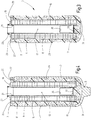
- FIG. 1 and 4 in the latter in a sectional view, shown as a whole embodiment of the filter device according to the invention comprises a filter housing 1, which is provided for receiving a filter element 3, the in Fig. 2 and 3 , in the latter in section, is shown separately.
- the filter housing 1 made of plastic or a metallic material has the shape of a hollow cylinder closed at the bottom 5, which is open at the opposite, upper end 7. The insertable from the open end 7 into the filter housing 1 filter element 3, which is designed in the manner of a so-called.
- Filter cartridge has a filter material 9 in the form of a pleated Filter mat, which in the usual manner in such filter cartridges a fluid-permeable support tube 11, preferably made of plastic, surrounds, within which an inner filter cavity 13 is located.
- a fluid-permeable support tube 11 preferably made of plastic
- a second, outer, fluid-permeable support tube 15 At the bottom in the drawing, the filter material 9 is enclosed by a closed end cap 17.
- an end cap 19 At the other end of the filter material 9 is an end cap 19, at which the connection is made to an associated filter head, which is not shown and via which the supply of a fluid to be cleaned and the discharge of purified fluid takes place.
- the end cap 19, which is injection molded in one piece as the closed end cap 17 of a plastic material, has a connection piece 21 for the fluid connection to the inner filter cavity 13, to which an O-ring 23 is located for sealing the filter head.
- the end cap 19 in outline is not completely circular, but has recesses extending inward in the radial direction.
- annular gaps 25 are formed between the end cap 19 and the edge 27 of a casing which surrounds the end cap 19.
- This has the shape of a pot 29, which extends from its open edge 27, forming a circular cylinder, to a closed bottom part 31.
- the closed at the bottom part 31 pot 29 which forms a sheath which completely surrounds the filter element 3 to the upper end cap 19, is made of a compressible material.
- the pot 29 forms an effective compensating device by compressing the material of the pot 29 by increasing the volume of the fluid space in the filter element 3 takes place, the pressure increases counteracts or even pressure peaks.
- materials for the pot 29, which are suitable for compression against the inner wall of the housing 1 are preferably porous compressible materials with closed pores in question.
- serving as a sheath pot 29 is formed of a sponge rubber, preferably an ethylene-propylene-diene rubber (EPDM).
- EPDM ethylene-propylene-diene rubber
- the pot 29 is a one-piece component with a bottom portion 31 axially inwardly projecting hump 33 as centering for the closed lower end cap 17. From the latter, starting a stabilizer 35 extends into the inner filter cavity thirteenth
- Pot 29 is formed, remain when removing a filter element to be replaced 3 residual fluids and deposited substances within the pot 29, which thus serves as a receptacle for contaminated media. Pollution of the housing during changes is avoided. Also in the filtration process contacting of the wall of the housing 1 by operating fluids is prevented by the pot 29 is pressed by the prevailing in the filtration process system pressure to the inner wall of the housing 1.
Landscapes
- Chemical & Material Sciences (AREA)
- Chemical Kinetics & Catalysis (AREA)
- Filtration Of Liquid (AREA)
- Filtering Of Dispersed Particles In Gases (AREA)
Claims (9)
- Système de filtration, comprenant au moins un élément (3) de filtre, qui peut être traversé par un fluide à épurer ayant une pression de fonctionnement pouvant être donnée à l'avance et qui peut être reçu dans une enveloppe (1), la pression du fluide régnant sur l'élément (3) de filtre pouvant avoir des pointes de pression ou d'une manière générale des élévations de pression endommageant l'élément (3) de filtre, notamment sa matière (9) filtrante, lesquelles peuvent être réduites et/ou lissées au moyen d'un dispositif de compensation, qui agit directement sur l'élément (3) de filtre et qui a au moins un élément (29) de compensation élastique, qui rend possible, en fonction d'une pointe de la pression ou d'une élévation de la pression, une augmentation du volume de l'espace réservé au fluide de l'enveloppe (1), l'élément (29) de compensation élastique étant disposé entre le côté extérieur de la matière (9) filtrante de l'élément (3) de filtre et la paroi intérieure voisine de l'enveloppe (1), l'élément de compensation élastique étant formé d'un gainage (29), au moins en partie du côté extérieur de l'élément (3) de filtre se trouvant dans l'enveloppe (1), le gainage ayant la forme d'un pot cylindrique de section circulaire, caractérisé en ce que le pot (29) s'applique du côté intérieur à un tube (15) support perméable au fluide et en ce que le tube (15) support s'applique, pour sa part, au côté extérieur de la matière (9) filtrante de l'élément (3) de filtre concerné, comme étant son tube (15) support extérieur.
- Installation de filtration suivant la revendication 1, caractérisé en ce qu'un gainage (29) est formé d'un corps d'une compressibilité donnée à l'avance.
- Installation de filtration suivant l'une des revendications précédentes, caractérisé en ce qu'un gainage (29) est en une matière poreuse à pores fermés, comme une matière mousse.
- Installation de filtration suivant l'une des revendications précédentes, caractérisée en ce qu'il est prévu un gainage (29) en caoutchouc mousse, de préférence en un caoutchouc éthylène-propylène-diène (EPDM).
- Installation de filtration suivant l'une des revendications précédentes, caractérisée en ce qu'il est prévu un élément (3) de filtre, ayant une matière (9) filtrante, entourant une cavité de filtre intérieure cylindrique creuse et enchâssée du côté de l'extrémité par une coiffe (19) d'extrémité formant l'entrée (25) et la sortie (21) de l'espace réservé au fluide et en ce que le gainage (29) entoure complètement l'élément (3) de filtre en laissant libre, au moins en partie, la coiffe (19) d'extrémité.
- Installation de filtration suivant l'une des revendications précédentes, caractérisé en ce que le côté extérieur du pot (29) du gainage s'applique au côté intérieur de l'enveloppe (1), en pouvant toutefois, lorsqu'il n'y a pas de pression de fonctionnement du fluide, être retiré de l'enveloppe (1) sous la forme d'une unité ensemble avec l'élément (3) de filtre.
- Elément de filtre, à utiliser notamment dans une installation de filtration suivant l'une des revendications 1 à 6, comprenant un gainage en une matière compressible, entourant au moins en partie le côté extérieur de l'élément (3) de filtre associé, le gainage ayant la forme d'un pot (29) cylindrique de section circulaire, caractérisé en ce que le pot (29) s'applique du côté intérieur à un tube (15) support perméable au fluide et en ce que le tube (15) support s'applique, pour sa part, au côté extérieur de la matière (9) filtrante de l'élément (3) de filtre concerné, comme étant son tube (15) support extérieur.
- Elément de filtre suivant la revendication 7, caractérisé en ce qu'il est prévu un gainage (29) en une matière poreuse à pores fermés, comme une matière mousse, de préférence un caoutchouc mousse.
- Elément de filtre suivant la revendication 7 ou 8, caractérisé en ce qu'il a une matière (9) filtrante, qui entoure une cavité (13) de filtre intérieure cylindrique creuse et qui est enchâssée du côté de l'extrémité par une coiffe (19) d'extrémité formant l'entrée (25) et la sortie (21) de l'espace réservé au fluide et en ce que le gainage (29) entoure complètement l'élément (3) de filtre en laissant libre, au moins en partie, la coiffe (19) d'extrémité.
Applications Claiming Priority (2)
| Application Number | Priority Date | Filing Date | Title |
|---|---|---|---|
| DE102012020431.0A DE102012020431A1 (de) | 2012-10-18 | 2012-10-18 | Filtervorrichtung |
| PCT/EP2013/003069 WO2014060084A1 (fr) | 2012-10-18 | 2013-10-11 | Dispositif filtre |
Publications (2)
| Publication Number | Publication Date |
|---|---|
| EP2908923A1 EP2908923A1 (fr) | 2015-08-26 |
| EP2908923B1 true EP2908923B1 (fr) | 2019-08-07 |
Family
ID=49474365
Family Applications (1)
| Application Number | Title | Priority Date | Filing Date |
|---|---|---|---|
| EP13780066.0A Active EP2908923B1 (fr) | 2012-10-18 | 2013-10-11 | Dispositif filtre |
Country Status (4)
| Country | Link |
|---|---|
| US (1) | US10143945B2 (fr) |
| EP (1) | EP2908923B1 (fr) |
| DE (1) | DE102012020431A1 (fr) |
| WO (1) | WO2014060084A1 (fr) |
Families Citing this family (6)
| Publication number | Priority date | Publication date | Assignee | Title |
|---|---|---|---|---|
| US9895633B2 (en) * | 2015-01-06 | 2018-02-20 | A.L. Filter Co., Ltd. | Freezing resistant liquid filter |
| DE102015010562A1 (de) | 2015-08-12 | 2017-02-16 | Hydac Filtertechnik Gmbh | Filtervorrichtung nebst Filterelement |
| DE102015010532A1 (de) | 2015-08-12 | 2017-02-16 | Hydac Filtertechnik Gmbh | Filtervorrichtung nebst Filterelement |
| DE102015010533A1 (de) | 2015-08-12 | 2017-02-16 | Hydac Filtertechnik Gmbh | Filtervorrichtung nebst Filterelement |
| US10100697B2 (en) | 2016-04-11 | 2018-10-16 | Tenneco Automotive Operating Company Inc. | Fluid delivery system for exhaust aftertreatment system |
| DE202024103109U1 (de) * | 2024-06-11 | 2024-07-01 | A.L. Filter Ead | Vorrichtung zur Filtration einer Harnstoff-Wasser-Lösung |
Citations (1)
| Publication number | Priority date | Publication date | Assignee | Title |
|---|---|---|---|---|
| DE2915730A1 (de) * | 1979-04-19 | 1980-10-30 | Kronsbein Dirk Gustav | Patronenfilter |
Family Cites Families (19)
| Publication number | Priority date | Publication date | Assignee | Title |
|---|---|---|---|---|
| US1059370A (en) * | 1912-05-13 | 1913-04-22 | John N Johnson | Means for relieving the walls of receptacles from undue internal pressure. |
| DE2121533A1 (de) * | 1971-05-03 | 1972-11-23 | Fa. Ing. Josef Wagner, 7991 Friedrichshafen-Fischbach | Hochdruck-Filter, insbesondere für Farbspritzanlagen |
| DE10220662B4 (de) * | 2002-05-10 | 2005-08-11 | Hydraulik-Ring Gmbh | Filterpatrone für flüssige, einfriergefährdete Medien, insbesondere für den Einsatz bei Brennstoffzellenfahrzeugen und bei Verbrennungskraftmaschinen, vorzugsweise Dieselmotoren |
| DE10220672B4 (de) | 2002-05-10 | 2008-01-03 | Hydraulik-Ring Gmbh | Filtereinheit für einfrierende Flüssigkeiten |
| US20050161394A1 (en) * | 2002-11-20 | 2005-07-28 | Karl Fritze | Freeze resistant water filter |
| DE102006003551B4 (de) | 2005-03-01 | 2008-09-11 | Mann+Hummel Gmbh | Filtereinrichtung zur Flüssigkeitsfilterung |
| KR100873294B1 (ko) * | 2007-06-14 | 2008-12-11 | 웅진코웨이주식회사 | 필터 조립체 |
| DE102008004344A1 (de) | 2008-01-15 | 2009-08-06 | Hydac Filtertechnik Gmbh | Filter |
| US8114299B2 (en) | 2008-02-28 | 2012-02-14 | Cummins Filtration Ip, Inc. | Filter with flow surge protection and method of protecting filter from flow surge |
| DE102009009899A1 (de) | 2009-02-20 | 2010-08-26 | Bayerische Motoren Werke Aktiengesellschaft | Kraftfahrzeug mit einer eine selektive katalytische Reduktion ermöglichenden Abgasanlage |
| DE102009011568B4 (de) | 2009-03-06 | 2010-12-23 | Mann + Hummel Gmbh | Filtereinrichtung für ein Kraftfahrzeug |
| JP5302087B2 (ja) * | 2009-04-27 | 2013-10-02 | スリーエム イノベイティブ プロパティズ カンパニー | 筒形フィルタ |
| DE102009023951B3 (de) * | 2009-06-04 | 2011-01-05 | Mann + Hummel Gmbh | Filtereinrichtung zur Flüssigkeitsfiltrierung |
| DE102010027069B3 (de) | 2010-07-13 | 2012-02-23 | Mann + Hummel Gmbh | Harnstoff-Wasser-Lösung-Filtersystem |
| DE102010061222B4 (de) * | 2010-12-14 | 2015-05-07 | Cummins Ltd. | SCR-Abgasnachbehandlungseinrichtung |
| DE102011013186B4 (de) * | 2011-03-05 | 2013-01-03 | Hydac Filtertechnik Gmbh | Filtervorrichtung |
| US20120248024A1 (en) | 2011-03-29 | 2012-10-04 | Kuss Filtration, Inc. | Filter with Inner-Sealed Pulsation Dampener |
| DE102012010981A1 (de) | 2012-06-02 | 2013-12-05 | Hydac Filtertechnik Gmbh | System zur Abgasnachbehandlung bei Verbrennungsmotoren |
| DE102012010979A1 (de) | 2012-06-02 | 2013-12-05 | Hydac Electronic Gmbh | System zur Abgasnachbehandlung bei Verbrennungsmotoren |
-
2012
- 2012-10-18 DE DE102012020431.0A patent/DE102012020431A1/de not_active Withdrawn
-
2013
- 2013-10-11 EP EP13780066.0A patent/EP2908923B1/fr active Active
- 2013-10-11 WO PCT/EP2013/003069 patent/WO2014060084A1/fr not_active Ceased
- 2013-10-11 US US14/433,425 patent/US10143945B2/en active Active
Patent Citations (1)
| Publication number | Priority date | Publication date | Assignee | Title |
|---|---|---|---|---|
| DE2915730A1 (de) * | 1979-04-19 | 1980-10-30 | Kronsbein Dirk Gustav | Patronenfilter |
Also Published As
| Publication number | Publication date |
|---|---|
| EP2908923A1 (fr) | 2015-08-26 |
| DE102012020431A1 (de) | 2014-04-24 |
| US20150258473A1 (en) | 2015-09-17 |
| US10143945B2 (en) | 2018-12-04 |
| WO2014060084A1 (fr) | 2014-04-24 |
Similar Documents
| Publication | Publication Date | Title |
|---|---|---|
| EP2908923B1 (fr) | Dispositif filtre | |
| DE102012003121B4 (de) | Filterkartusche für eine Reduktionsmittelfördervorrichtung | |
| EP3854470B1 (fr) | Installation de filtre et élément de filtre rond, en particulier pour la filtration de gaz | |
| EP3096859B1 (fr) | Élément de filtration | |
| EP3017854B1 (fr) | Filtre destiné à filtrer un fluide | |
| EP3620220B1 (fr) | Dispositif filtrant | |
| DE102016001025A1 (de) | Filterelement eines Flüssigkeitsfilters, Flüssigkeitsfilter und Filtergehäuse | |
| EP2865433A2 (fr) | Élément de filtre et système de filtre pour un milieu fluidique, notamment du carburant diesel | |
| EP3334513B1 (fr) | Dispositif filtrant et élément filtrant | |
| EP2845636A1 (fr) | Élément de filtre et procédé de fabrication d'un élément de filtre | |
| EP2854987B1 (fr) | Système de retraitement des gaz d'échappement de moteurs à combustion interne ainsi que d'amortissement des pulsations et/ou de lissage du débit volumétrique de fluides | |
| EP1671692B1 (fr) | Filtre à liquide avec clapet anti-retour | |
| EP3334514B1 (fr) | Dispositif filtrant | |
| WO2019110361A1 (fr) | Élément filtrant rond d'un filtre pour solution aqueuse d'urée et filtre | |
| DE102012003156B4 (de) | Filterkartusche für eine gefriergefährdete Flüssigkeit | |
| EP3334515B1 (fr) | Dispositif filtrant | |
| DE102017011437A1 (de) | Filter einer Filtervorrichtung zur Filtrierung von Fluid und Filterkopf einer Filtervorrichtung | |
| DE202008004290U1 (de) | Filterverschluss-System | |
| DE102013004865B4 (de) | Filtereinrichtung mit einem ringförmigen Filterelement | |
| DE112017005430B4 (de) | Flüssigkeitsreinigungselement, Flüssigkeitsreinigungssystem und Verfahren zur Herstellung eines Flüssigkeitsreinigungselements | |
| DE102009026764A1 (de) | Schwalltopf sowie Abgasreinigungseinrichtung | |
| DE102010039053A1 (de) | Filtereinrichtung sowie Ansaugvorrichtung | |
| DE102022209308A1 (de) | Filterelement | |
| DE102017210231A1 (de) | Filtereinrichtung und Fördermodul für ein Fluid sowie Betriebsverfahren hierzu | |
| DE102017201140A1 (de) | Filteranordnung für einen Reduktionsmittel-Vorratstank oder eine Funktionseinheit |
Legal Events
| Date | Code | Title | Description |
|---|---|---|---|
| PUAI | Public reference made under article 153(3) epc to a published international application that has entered the european phase |
Free format text: ORIGINAL CODE: 0009012 |
|
| 17P | Request for examination filed |
Effective date: 20150317 |
|
| AK | Designated contracting states |
Kind code of ref document: A1 Designated state(s): AL AT BE BG CH CY CZ DE DK EE ES FI FR GB GR HR HU IE IS IT LI LT LU LV MC MK MT NL NO PL PT RO RS SE SI SK SM TR |
|
| AX | Request for extension of the european patent |
Extension state: BA ME |
|
| DAX | Request for extension of the european patent (deleted) | ||
| STAA | Information on the status of an ep patent application or granted ep patent |
Free format text: STATUS: EXAMINATION IS IN PROGRESS |
|
| 17Q | First examination report despatched |
Effective date: 20170807 |
|
| GRAP | Despatch of communication of intention to grant a patent |
Free format text: ORIGINAL CODE: EPIDOSNIGR1 |
|
| STAA | Information on the status of an ep patent application or granted ep patent |
Free format text: STATUS: GRANT OF PATENT IS INTENDED |
|
| INTG | Intention to grant announced |
Effective date: 20190409 |
|
| GRAS | Grant fee paid |
Free format text: ORIGINAL CODE: EPIDOSNIGR3 |
|
| GRAA | (expected) grant |
Free format text: ORIGINAL CODE: 0009210 |
|
| STAA | Information on the status of an ep patent application or granted ep patent |
Free format text: STATUS: THE PATENT HAS BEEN GRANTED |
|
| AK | Designated contracting states |
Kind code of ref document: B1 Designated state(s): AL AT BE BG CH CY CZ DE DK EE ES FI FR GB GR HR HU IE IS IT LI LT LU LV MC MK MT NL NO PL PT RO RS SE SI SK SM TR |
|
| REG | Reference to a national code |
Ref country code: GB Ref legal event code: FG4D Free format text: NOT ENGLISH |
|
| REG | Reference to a national code |
Ref country code: CH Ref legal event code: EP Ref country code: AT Ref legal event code: REF Ref document number: 1162946 Country of ref document: AT Kind code of ref document: T Effective date: 20190815 |
|
| REG | Reference to a national code |
Ref country code: DE Ref legal event code: R096 Ref document number: 502013013331 Country of ref document: DE |
|
| REG | Reference to a national code |
Ref country code: IE Ref legal event code: FG4D Free format text: LANGUAGE OF EP DOCUMENT: GERMAN |
|
| REG | Reference to a national code |
Ref country code: NL Ref legal event code: MP Effective date: 20190807 |
|
| REG | Reference to a national code |
Ref country code: LT Ref legal event code: MG4D |
|
| PG25 | Lapsed in a contracting state [announced via postgrant information from national office to epo] |
Ref country code: NL Free format text: LAPSE BECAUSE OF FAILURE TO SUBMIT A TRANSLATION OF THE DESCRIPTION OR TO PAY THE FEE WITHIN THE PRESCRIBED TIME-LIMIT Effective date: 20190807 Ref country code: SE Free format text: LAPSE BECAUSE OF FAILURE TO SUBMIT A TRANSLATION OF THE DESCRIPTION OR TO PAY THE FEE WITHIN THE PRESCRIBED TIME-LIMIT Effective date: 20190807 Ref country code: BG Free format text: LAPSE BECAUSE OF FAILURE TO SUBMIT A TRANSLATION OF THE DESCRIPTION OR TO PAY THE FEE WITHIN THE PRESCRIBED TIME-LIMIT Effective date: 20191107 Ref country code: NO Free format text: LAPSE BECAUSE OF FAILURE TO SUBMIT A TRANSLATION OF THE DESCRIPTION OR TO PAY THE FEE WITHIN THE PRESCRIBED TIME-LIMIT Effective date: 20191107 Ref country code: LT Free format text: LAPSE BECAUSE OF FAILURE TO SUBMIT A TRANSLATION OF THE DESCRIPTION OR TO PAY THE FEE WITHIN THE PRESCRIBED TIME-LIMIT Effective date: 20190807 Ref country code: FI Free format text: LAPSE BECAUSE OF FAILURE TO SUBMIT A TRANSLATION OF THE DESCRIPTION OR TO PAY THE FEE WITHIN THE PRESCRIBED TIME-LIMIT Effective date: 20190807 Ref country code: PT Free format text: LAPSE BECAUSE OF FAILURE TO SUBMIT A TRANSLATION OF THE DESCRIPTION OR TO PAY THE FEE WITHIN THE PRESCRIBED TIME-LIMIT Effective date: 20191209 Ref country code: HR Free format text: LAPSE BECAUSE OF FAILURE TO SUBMIT A TRANSLATION OF THE DESCRIPTION OR TO PAY THE FEE WITHIN THE PRESCRIBED TIME-LIMIT Effective date: 20190807 |
|
| PG25 | Lapsed in a contracting state [announced via postgrant information from national office to epo] |
Ref country code: LV Free format text: LAPSE BECAUSE OF FAILURE TO SUBMIT A TRANSLATION OF THE DESCRIPTION OR TO PAY THE FEE WITHIN THE PRESCRIBED TIME-LIMIT Effective date: 20190807 Ref country code: AL Free format text: LAPSE BECAUSE OF FAILURE TO SUBMIT A TRANSLATION OF THE DESCRIPTION OR TO PAY THE FEE WITHIN THE PRESCRIBED TIME-LIMIT Effective date: 20190807 Ref country code: RS Free format text: LAPSE BECAUSE OF FAILURE TO SUBMIT A TRANSLATION OF THE DESCRIPTION OR TO PAY THE FEE WITHIN THE PRESCRIBED TIME-LIMIT Effective date: 20190807 Ref country code: IS Free format text: LAPSE BECAUSE OF FAILURE TO SUBMIT A TRANSLATION OF THE DESCRIPTION OR TO PAY THE FEE WITHIN THE PRESCRIBED TIME-LIMIT Effective date: 20191207 Ref country code: GR Free format text: LAPSE BECAUSE OF FAILURE TO SUBMIT A TRANSLATION OF THE DESCRIPTION OR TO PAY THE FEE WITHIN THE PRESCRIBED TIME-LIMIT Effective date: 20191108 Ref country code: ES Free format text: LAPSE BECAUSE OF FAILURE TO SUBMIT A TRANSLATION OF THE DESCRIPTION OR TO PAY THE FEE WITHIN THE PRESCRIBED TIME-LIMIT Effective date: 20190807 |
|
| PG25 | Lapsed in a contracting state [announced via postgrant information from national office to epo] |
Ref country code: TR Free format text: LAPSE BECAUSE OF FAILURE TO SUBMIT A TRANSLATION OF THE DESCRIPTION OR TO PAY THE FEE WITHIN THE PRESCRIBED TIME-LIMIT Effective date: 20190807 |
|
| PG25 | Lapsed in a contracting state [announced via postgrant information from national office to epo] |
Ref country code: DK Free format text: LAPSE BECAUSE OF FAILURE TO SUBMIT A TRANSLATION OF THE DESCRIPTION OR TO PAY THE FEE WITHIN THE PRESCRIBED TIME-LIMIT Effective date: 20190807 Ref country code: IT Free format text: LAPSE BECAUSE OF FAILURE TO SUBMIT A TRANSLATION OF THE DESCRIPTION OR TO PAY THE FEE WITHIN THE PRESCRIBED TIME-LIMIT Effective date: 20190807 Ref country code: EE Free format text: LAPSE BECAUSE OF FAILURE TO SUBMIT A TRANSLATION OF THE DESCRIPTION OR TO PAY THE FEE WITHIN THE PRESCRIBED TIME-LIMIT Effective date: 20190807 Ref country code: PL Free format text: LAPSE BECAUSE OF FAILURE TO SUBMIT A TRANSLATION OF THE DESCRIPTION OR TO PAY THE FEE WITHIN THE PRESCRIBED TIME-LIMIT Effective date: 20190807 Ref country code: RO Free format text: LAPSE BECAUSE OF FAILURE TO SUBMIT A TRANSLATION OF THE DESCRIPTION OR TO PAY THE FEE WITHIN THE PRESCRIBED TIME-LIMIT Effective date: 20190807 |
|
| PG25 | Lapsed in a contracting state [announced via postgrant information from national office to epo] |
Ref country code: IS Free format text: LAPSE BECAUSE OF FAILURE TO SUBMIT A TRANSLATION OF THE DESCRIPTION OR TO PAY THE FEE WITHIN THE PRESCRIBED TIME-LIMIT Effective date: 20200224 Ref country code: MC Free format text: LAPSE BECAUSE OF FAILURE TO SUBMIT A TRANSLATION OF THE DESCRIPTION OR TO PAY THE FEE WITHIN THE PRESCRIBED TIME-LIMIT Effective date: 20190807 Ref country code: CZ Free format text: LAPSE BECAUSE OF FAILURE TO SUBMIT A TRANSLATION OF THE DESCRIPTION OR TO PAY THE FEE WITHIN THE PRESCRIBED TIME-LIMIT Effective date: 20190807 Ref country code: SK Free format text: LAPSE BECAUSE OF FAILURE TO SUBMIT A TRANSLATION OF THE DESCRIPTION OR TO PAY THE FEE WITHIN THE PRESCRIBED TIME-LIMIT Effective date: 20190807 Ref country code: SM Free format text: LAPSE BECAUSE OF FAILURE TO SUBMIT A TRANSLATION OF THE DESCRIPTION OR TO PAY THE FEE WITHIN THE PRESCRIBED TIME-LIMIT Effective date: 20190807 |
|
| REG | Reference to a national code |
Ref country code: CH Ref legal event code: PL |
|
| REG | Reference to a national code |
Ref country code: DE Ref legal event code: R097 Ref document number: 502013013331 Country of ref document: DE |
|
| PLBE | No opposition filed within time limit |
Free format text: ORIGINAL CODE: 0009261 |
|
| STAA | Information on the status of an ep patent application or granted ep patent |
Free format text: STATUS: NO OPPOSITION FILED WITHIN TIME LIMIT |
|
| PG2D | Information on lapse in contracting state deleted |
Ref country code: IS |
|
| PG25 | Lapsed in a contracting state [announced via postgrant information from national office to epo] |
Ref country code: LI Free format text: LAPSE BECAUSE OF NON-PAYMENT OF DUE FEES Effective date: 20191031 Ref country code: LU Free format text: LAPSE BECAUSE OF NON-PAYMENT OF DUE FEES Effective date: 20191011 Ref country code: CH Free format text: LAPSE BECAUSE OF NON-PAYMENT OF DUE FEES Effective date: 20191031 |
|
| 26N | No opposition filed |
Effective date: 20200603 |
|
| REG | Reference to a national code |
Ref country code: BE Ref legal event code: MM Effective date: 20191031 |
|
| PG25 | Lapsed in a contracting state [announced via postgrant information from national office to epo] |
Ref country code: SI Free format text: LAPSE BECAUSE OF FAILURE TO SUBMIT A TRANSLATION OF THE DESCRIPTION OR TO PAY THE FEE WITHIN THE PRESCRIBED TIME-LIMIT Effective date: 20190807 Ref country code: BE Free format text: LAPSE BECAUSE OF NON-PAYMENT OF DUE FEES Effective date: 20191031 |
|
| PG25 | Lapsed in a contracting state [announced via postgrant information from national office to epo] |
Ref country code: IE Free format text: LAPSE BECAUSE OF NON-PAYMENT OF DUE FEES Effective date: 20191011 |
|
| REG | Reference to a national code |
Ref country code: AT Ref legal event code: MM01 Ref document number: 1162946 Country of ref document: AT Kind code of ref document: T Effective date: 20191011 |
|
| PG25 | Lapsed in a contracting state [announced via postgrant information from national office to epo] |
Ref country code: AT Free format text: LAPSE BECAUSE OF NON-PAYMENT OF DUE FEES Effective date: 20191011 |
|
| PG25 | Lapsed in a contracting state [announced via postgrant information from national office to epo] |
Ref country code: CY Free format text: LAPSE BECAUSE OF FAILURE TO SUBMIT A TRANSLATION OF THE DESCRIPTION OR TO PAY THE FEE WITHIN THE PRESCRIBED TIME-LIMIT Effective date: 20190807 |
|
| PG25 | Lapsed in a contracting state [announced via postgrant information from national office to epo] |
Ref country code: MT Free format text: LAPSE BECAUSE OF FAILURE TO SUBMIT A TRANSLATION OF THE DESCRIPTION OR TO PAY THE FEE WITHIN THE PRESCRIBED TIME-LIMIT Effective date: 20190807 Ref country code: HU Free format text: LAPSE BECAUSE OF FAILURE TO SUBMIT A TRANSLATION OF THE DESCRIPTION OR TO PAY THE FEE WITHIN THE PRESCRIBED TIME-LIMIT; INVALID AB INITIO Effective date: 20131011 |
|
| PG25 | Lapsed in a contracting state [announced via postgrant information from national office to epo] |
Ref country code: MK Free format text: LAPSE BECAUSE OF FAILURE TO SUBMIT A TRANSLATION OF THE DESCRIPTION OR TO PAY THE FEE WITHIN THE PRESCRIBED TIME-LIMIT Effective date: 20190807 |
|
| PGFP | Annual fee paid to national office [announced via postgrant information from national office to epo] |
Ref country code: GB Payment date: 20250808 Year of fee payment: 13 |
|
| PGFP | Annual fee paid to national office [announced via postgrant information from national office to epo] |
Ref country code: FR Payment date: 20250829 Year of fee payment: 13 |
|
| PGFP | Annual fee paid to national office [announced via postgrant information from national office to epo] |
Ref country code: DE Payment date: 20251031 Year of fee payment: 13 |