EP2908974B1 - Alésoir et procédé pour le fabriquer - Google Patents
Alésoir et procédé pour le fabriquer Download PDFInfo
- Publication number
- EP2908974B1 EP2908974B1 EP13776790.1A EP13776790A EP2908974B1 EP 2908974 B1 EP2908974 B1 EP 2908974B1 EP 13776790 A EP13776790 A EP 13776790A EP 2908974 B1 EP2908974 B1 EP 2908974B1
- Authority
- EP
- European Patent Office
- Prior art keywords
- reamer
- cutting
- support
- section
- reaming
- Prior art date
- Legal status (The legal status is an assumption and is not a legal conclusion. Google has not performed a legal analysis and makes no representation as to the accuracy of the status listed.)
- Active
Links
Images



Classifications
-
- B—PERFORMING OPERATIONS; TRANSPORTING
- B23—MACHINE TOOLS; METAL-WORKING NOT OTHERWISE PROVIDED FOR
- B23D—PLANING; SLOTTING; SHEARING; BROACHING; SAWING; FILING; SCRAPING; LIKE OPERATIONS FOR WORKING METAL BY REMOVING MATERIAL, NOT OTHERWISE PROVIDED FOR
- B23D77/00—Reaming tools
- B23D77/02—Reamers with inserted cutting edges
-
- B—PERFORMING OPERATIONS; TRANSPORTING
- B23—MACHINE TOOLS; METAL-WORKING NOT OTHERWISE PROVIDED FOR
- B23P—METAL-WORKING NOT OTHERWISE PROVIDED FOR; COMBINED OPERATIONS; UNIVERSAL MACHINE TOOLS
- B23P15/00—Making specific metal objects by operations not covered by a single other subclass or a group in this subclass
- B23P15/28—Making specific metal objects by operations not covered by a single other subclass or a group in this subclass cutting tools
- B23P15/46—Making specific metal objects by operations not covered by a single other subclass or a group in this subclass cutting tools reaming tools
-
- B—PERFORMING OPERATIONS; TRANSPORTING
- B23—MACHINE TOOLS; METAL-WORKING NOT OTHERWISE PROVIDED FOR
- B23D—PLANING; SLOTTING; SHEARING; BROACHING; SAWING; FILING; SCRAPING; LIKE OPERATIONS FOR WORKING METAL BY REMOVING MATERIAL, NOT OTHERWISE PROVIDED FOR
- B23D2277/00—Reaming tools
- B23D2277/06—Connections between component parts
- B23D2277/061—Brazed connections
-
- B—PERFORMING OPERATIONS; TRANSPORTING
- B23—MACHINE TOOLS; METAL-WORKING NOT OTHERWISE PROVIDED FOR
- B23D—PLANING; SLOTTING; SHEARING; BROACHING; SAWING; FILING; SCRAPING; LIKE OPERATIONS FOR WORKING METAL BY REMOVING MATERIAL, NOT OTHERWISE PROVIDED FOR
- B23D2277/00—Reaming tools
- B23D2277/06—Connections between component parts
- B23D2277/065—Glued connections
-
- B—PERFORMING OPERATIONS; TRANSPORTING
- B23—MACHINE TOOLS; METAL-WORKING NOT OTHERWISE PROVIDED FOR
- B23D—PLANING; SLOTTING; SHEARING; BROACHING; SAWING; FILING; SCRAPING; LIKE OPERATIONS FOR WORKING METAL BY REMOVING MATERIAL, NOT OTHERWISE PROVIDED FOR
- B23D2277/00—Reaming tools
- B23D2277/20—Number of cutting edges
- B23D2277/201—One
-
- B—PERFORMING OPERATIONS; TRANSPORTING
- B23—MACHINE TOOLS; METAL-WORKING NOT OTHERWISE PROVIDED FOR
- B23D—PLANING; SLOTTING; SHEARING; BROACHING; SAWING; FILING; SCRAPING; LIKE OPERATIONS FOR WORKING METAL BY REMOVING MATERIAL, NOT OTHERWISE PROVIDED FOR
- B23D2277/00—Reaming tools
- B23D2277/24—Materials of the tool or the intended workpiece, methods of applying these materials
- B23D2277/2435—Cubic boron nitride [CBN]
-
- B—PERFORMING OPERATIONS; TRANSPORTING
- B23—MACHINE TOOLS; METAL-WORKING NOT OTHERWISE PROVIDED FOR
- B23D—PLANING; SLOTTING; SHEARING; BROACHING; SAWING; FILING; SCRAPING; LIKE OPERATIONS FOR WORKING METAL BY REMOVING MATERIAL, NOT OTHERWISE PROVIDED FOR
- B23D2277/00—Reaming tools
- B23D2277/24—Materials of the tool or the intended workpiece, methods of applying these materials
- B23D2277/2442—Diamond
- B23D2277/245—Diamond polycrystalline [PCD]
Definitions
- the present invention relates to a reamer according to the preamble of claim 1.
- a reamer is from WO 2008/133295 A1 known.
- the present invention also relates to a method for producing a reamer.
- Reamers also known as broaching reamers, are tools that are used for finishing bores by reaming. By rubbing, the surface quality of the bores as well as the shape and dimensional accuracy can be improved compared to the originally produced bores.
- reamers can have a plurality of cutting edges distributed over the circumference, which are separated from one another by grooves running parallel to the longitudinal axis.
- Alternative reamers are inclined to the left so that chips can be removed in the direction of insertion.
- Right-hand pitch reamers can be used for blind holes.
- HSS hard metal, cermet, polycrystalline diamond or boron nitride
- Hard machining can also be carried out, in particular when using boron nitride for the cutting elements.
- a device for machining concave surfaces in which a plate element is fixed eccentrically with respect to a longitudinal axis of a carrier section on a carrier surface of the carrier section.
- the cutting plate has a convex cutting edge, by means of which the concave surfaces on the workpiece can be produced.
- a reamer is known in which a plurality of plate-shaped cutting elements are attached to support surfaces which are planar but which are inclined to the longitudinal axis.
- the JP 2010-179439 A a reamer is known in which a prism-shaped cutting element is inserted into a holder with a wedge-shaped receiving surface.
- the cutting element can be attached eccentrically to the carrier section. In this way, the reamer can be easily produced by attaching the cutting element to the tangential support surface.
- this construction then basically enables reamers with small diameters to be realized, which can be smaller than 1 mm, for example.
- the reamer can be clamped in a chuck of a tool drive or attached to a stationary tool holder.
- the cutting element is designed as a plate element which has a bearing surface that rests on the carrier surface.
- the planar support of the plate element on the support surface achieves a high degree of connection strength.
- the plate element is preferably rectangular in the radial plan view, with a side edge parallel to the longitudinal axis.
- the other side edge is preferably at least 0.2 times, but in particular at least 0.7 times as large as the friction diameter.
- At least one corner of the plate element is designed as a cutting corner.
- the plate element is arranged in relation to the carrier section in such a way that a cutting corner is formed on the plate element which lies in the intersection area of an outer surface opposite the support surface, a front end surface and a first side surface of the plate element.
- the cutting corner consequently lies on a radially outer region of the plate element when this is fixed on the carrier surface, so that the reamer function can be implemented in a structurally simple manner.
- the cutting element has a circular bevel oriented concentrically to the longitudinal axis.
- the reamer can automatically guide itself in the bore when the reaming process is carried out.
- the round bevel is included formed on the cutting element, which is preferably made of a hard material, so that the guide property is subject to little wear.
- round bevel can also be formed axially adjacent to the cutting element on the neck section in order to implement guidance within the bore over the greatest possible length of the neck section.
- the carrier section has at least one carrier surface which is oriented at a carrier surface angle greater than 0 ° and less than 90 ° with respect to the longitudinal axis, an outer surface of the cutting element being oriented parallel to the longitudinal axis.
- the carrier surface is enlarged on the one hand, since it runs obliquely to the longitudinal axis.
- this increases the stability of the carrier section, since it can be made with a greater material thickness due to the carrier surface angle in an area facing the neck section.
- the cutting element can be guided with greater stability by means of the carrier section.
- the support surface angle is in the range from 2 ° to 45 °, in particular in the range from 3 ° to 30 °, and particularly preferably in the range from 5 ° to 15 °.
- the cutting element is firmly connected to the carrier section, in particular via an adhesive or soldered connection.
- connection is via a flat soldered connection or flat adhesive connection he follows. In this way, a high connection strength can be achieved.
- welding techniques or other connection techniques for this purpose.
- the reamer has a friction diameter of 0.2 mm to 30 mm, in particular in a range from 0.2 mm to 5 mm, in particular in a range from 0.2 mm to 3 mm, and particularly preferred in a range from 0.5 mm to 2 mm.
- the reamer can also have a diameter range of 0.2 mm to 0.9 mm.
- the carrier section has two carrier surfaces which are each aligned at a carrier surface angle greater than 0 ° and less than 90 ° with respect to the longitudinal axis, in such a way that the carrier surfaces at a front end of the friction section are spaced closer to one another than in one rear end of the friction section pointing towards the neck section.
- the carrier section can be designed to taper conically in longitudinal section, so that a high degree of connection strength can be achieved between the carrier section and the neck section.
- the carrier section is preferably formed in one piece with the neck section.
- the support surface can in particular be aligned eccentrically, that is to say for example tangentially, with respect to the longitudinal axis.
- the above-mentioned surfaces are in particular designed as flat surfaces.
- the production of the finished dimension of the friction section can include providing a round bevel on the plate element and / or on a neck section of the reamer. Furthermore, the production of the finished dimension can include forming a free surface in the area of a cutting corner, which is aligned obliquely to the longitudinal axis.
- a cutting edge can be set up which is skewed to the longitudinal axis and by means of which the rubbing takes place in a "peeling" manner in that the actual cutting process moves along the cutting edge during the rubbing.
- the plate element has a carrier layer and a layer made of a cutting material.
- Such plate elements can be manufactured inexpensively and made available "off the shelf”.
- the plate element is fixed with the cutting material layer on the carrier surface.
- the carrier layer protrudes in the radial direction with respect to the cutting material layer.
- the production of the finished size of the friction section includes removing the carrier layer at least partially, but in particular completely.
- a one-piece cutting element made from a cutting material is attached to the support portion of the reamer.
- the fixing can be done by soldering or by gluing or by other suitable connection methods.
- the carrier section has a plurality of carrier surfaces, on each of which a plate element is fixed in the manner described above.
- a polygonal shape in the axial plan view of the end of the reamer in the manufactured state, essentially a polygonal shape can be achieved, in particular a square shape.
- the four corner areas of such a square can each have cutting corners.
- the circular chord sections between the side edges of this square shape and the friction diameter form chip spaces in the shape of a segment of a circle, so that it is not necessary to design the friction section with special chip spaces.
- two plate elements can be attached to the carrier section.
- the finished dimension of the friction section can be formed, for example, by grinding or lasering.
- a hole can be provided in the carrier section in the area between two plate elements in order to supply cooling or lubricating liquid via this.
- reamers with a very small working diameter can be produced with the present invention. Furthermore, at the same time a relatively large area is provided for the connection between the carrier section and the cutting element, so that a firm connection is possible. In particular in the case of a conically widening carrier section, a rigid connection can be established between the friction section and the neck section.
- the carrier surfaces can merge directly into one another at their front end, so that the distance in the front end of the friction section is equal to zero.
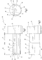
- a reamer is shown schematically and generally designated 10.
- the reamer 10 has a shaft section 14 which is aligned along a longitudinal axis 12.
- a neck section 16 which is also aligned along the longitudinal axis 12, extends from the shaft section 14.
- the neck section 16 and the shaft section 14 are formed integrally with one another and are made, for example, from a conventional tool steel or hard metal or heavy metal.
- a friction section 18 adjoins the neck section 16 in the axial direction.
- the friction section 18 includes a carrier section 20, which is preferably designed in one piece with the neck section 16, a cutting element 22 being fixed to the carrier section 20, which can be designed in particular as a plate element or cutting plate.
- the cutting element 22 can in particular comprise a CBN material, but can also comprise other cutting materials such as cermet etc.
- the carrier section 20 has a carrier surface 30 which is oriented tangentially to the longitudinal axis 12.
- the cutting element 22 is fixed flat on the carrier surface 30 in such a way that the cutting element 22 is arranged eccentrically with respect to the longitudinal axis 12.
- the cutting element 22 has a front end face 32 and a support surface 34.
- the support surface 34 is connected flatly to the carrier surface 30, for example by soldering, by gluing or by other connection methods.
- the cutting element 22 On the side opposite to the support surface 34, the cutting element 22 has an outer surface 36 which, in the present embodiment, is formed parallel to the support surface 34. Furthermore, the cutting element 22 has a rear end face 38 which can rest against a radial shoulder of the neck section 16, for example.
- the cutting element 22 further includes a first side surface 40 and an opposing second side surface 42.
- a first cutting corner of the reamer 10 is formed in the region of a point of intersection between the front end face 32, the outer face 36 and the first side face 40.
- the reamer 10 can be provided with suitable chamfers. Furthermore, on the outer circumference of the cutting element 22 is one in the Figs. 1 to 3 unspecified round bevel formed, which is used for guidance purposes. Furthermore, in the area of the cutting corner 44, a free surface can be formed by which a cutting edge is formed.
- the cutting corner 44 defines a friction diameter 46, which in Fig. 2 is shown.
- a guide section 48 can be formed on the carrier section 20 and / or on the neck section 16, which in the present case is formed at a distance from the friction diameter 46.
- the guide section 48 can, however, also coincide with the friction diameter 46 and ensure suitable axial guidance along the longitudinal axis 12.
- the radius of the guide section 48 can coincide with the abovementioned circular bevel.
- the cutting element 22 is designed as a plate element and has a substantially cuboid shape.
- planar connection between the support surface 30 and the support surface 34 results in a high connection strength between the cutting element 22 and the support section 20.
- a reamer 10 'according to the invention is shown in which the support surface 30' is oriented at a support surface angle 50 in the range of greater than 0 ° and less than 90 ° with respect to the longitudinal axis.
- the support surface angle can be in the range from 2 ° to 45 °, particularly preferably in the range from 3 ° to 30 °, particularly preferably in the range from 5 ° to 15 ° or from 10 ° to 20 °.
- the support surface angle 50 By forming the support surface angle 50, the area of the connection between cutting element 22 and support section 20 can be enlarged. On the other hand, with a given friction diameter, the material thickness at the transition between carrier section 20 'and neck section 16' can be increased, so that carrier section 20 'is connected to neck section 16' with greater strength.
- the support surface 34 'and the outer surface 36' consequently do not run parallel but are aligned with one another at the support surface angle 50.
- FIG. 6 to 9 Another embodiment of a reamer 10 ′′ according to the invention is shown. In terms of structure and mode of operation, this generally corresponds to the reamer 10 ′ of FIG Figures 4 and 5 . The main differences are explained below.
- the shaft section 14 has an anti-rotation section 52.
- two cutting elements 22 in the form of plate elements are fixed on the carrier section 20 ′′, to be precise on opposite sides of the longitudinal axis 12.
- the cutting elements 22 can each be designed like the cutting element 22 'of Figures 4 and 5 and are denoted by 22A, 22B in the figures.
- the correspondingly provided support surfaces 30A, 30B are aligned at an angle to one another which corresponds to twice the support surface angle and can be, for example, in the range from 10 ° to 40 °, in particular in the range from 10 ° to 30 °.
- the carrier section 20 ′′ is conical in longitudinal section, the carrier surfaces 30A, 30B adjacent to the neck section 16 ′′ being further spaced apart from one another than in the area of the free end of the carrier section 20.
- the two cutting elements 22A, 22B form two opposite sections of a square shape.
- a cutting corner 44 ′′ can be formed in the area of each corner of the square shape.
- the diagonal of the square defines the friction diameter 46.
- the height of the square is in Fig. 9 shown at 54, the side length of the square being less than the friction diameter 46.
- Fig. 9 the radial residual thickness 56 of the carrier section 20 "is also shown in the region of its front free end.
- Fig. 9 shows Fig. 9 that the friction section 18 and the neck section 16 can have a round bevel 58 which, viewed in the axial direction, is aligned with the cutting corners 44 ′′.
- the reamer 10 can be supported in the bore evenly distributed over the circumference when rubbing.
- the circular segment-shaped areas between the side edges of the square shape and the friction diameter 46 form circular segment-shaped chip spaces.
- FIG. 10 is shown where, as an example, six cutting elements 22A to 22F are fixed on a polygonal support section 20 '". It is understood that three, four, five, seven or more cutting elements 22 can also be fixed on a support section 20.
- Fig. 11 shows a variant that is generally similar to the embodiment of FIG Figures 6 to 9 corresponds, but is not the subject of the claimed invention.
- the two plate members 22A, 22B are the Figures 6 to 9 each divided into two partial plate elements, which are arranged in the area of the corners of a square and in Fig. 11 are designated by 22A to 22D.
- the carrier section 20 IV of the Fig. 11 is cross-shaped in this embodiment in plan view.
- the embodiment of the Fig. 11 can also be realized with only two diagonally opposite partial plate elements (for example 22A, 22C). Furthermore, a plurality of three, four, five, six, seven, eight such partial plate elements can be arranged distributed over the circumference.
- the carrier section 20 IV is designed to be reinforced.
- the embodiment of the Figures 6 to 9 however has the The advantage that a larger connecting surface between the cutting elements 22 and the carrier section 20 can be realized and / or only two surfaces are designed as connecting surfaces, so that the manufacturing effort in the embodiment of FIG Figures 6 to 9 is decreased.
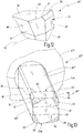
- Fig. 12 shows a schematic view of a reamer 10 V , which can be any of the above-mentioned reamers. It is in Fig. 12 a region of a cutting corner 44 of a cutting element 22 is shown, which is fixed to a carrier section 20. For one thing, in Fig. 12 It can be seen that a circular bevel 58 is formed on the cutting element 22, which is oriented concentrically to the friction diameter 46 and extends in a direction parallel to the longitudinal axis 12. The round bevel 58 can extend in the axial direction beyond the cutting element 22, in particular into the region of the neck section 16.
- a free surface 60 is provided, which is aligned obliquely to the longitudinal axis 12.
- a cutting edge 62 is formed by the free surface 60, which is also aligned obliquely to the longitudinal axis 12.
- the cutting edge 62 is formed on an edge of the outer surface 36.
- FIG. 10 shows a further embodiment of a reamer 10 VI , which is generally similar to the reamer 10 ′′ of FIG Figures 6 to 9 corresponds to. The same elements are therefore identified by the same reference symbols.
- the round bevel 58 is formed in the area of edges that are formed at the transition between the outer surfaces 36 and the side surfaces 40, 42, and can extend over the neck portion 16 VI in the axial direction.
- the neck section 16 VI is presently also square in cross section, as in the embodiment of FIG Figures 6 to 9 .
- Fig. 13 the free surface 60 can also be seen, which is formed in the area of each of the cutting corners 44 and leads to the formation of four cutting edges 62.
- a reamer blank 70 is provided, which has an outer diameter equal to the diameter of the shaft section 12.
- a recess 72 is then formed in a front end region of this reamer blank 70, which recess 72 can be produced, for example, by erosion.
- the recess 72 can be ring-shaped with a polygonal shape.
- the recess 72 forms the opposing support surfaces to which cutting elements 22A, 22B are applied.
- the cutting elements 22A, 22B are designed as plate elements 74A, 74B, each of which has a carrier layer 76 and a cutting material layer 78. These layers are aligned parallel to the bearing surfaces 34A, 34B.
- the plate elements 74A, 74B are attached to the carrier surfaces 30A, 30B in such a way that the cutting material layers 78A, 78B lie directly on the carrier surfaces and the respective carrier layers 76A, 76B lie radially on the outside.
- the final dimension of the friction section is produced by removing the reamer blank 70 to the friction diameter 46 in an area that defines the friction section 18 and the neck section 16, the friction diameter 46 (see Fig. 14 ) is smaller than the smallest inner circumferential section of the backing layers 76A, 76B.
- These carrier layers 76A, 76B are completely removed during the grinding process on the friction diameter 46, so that ultimately a cutting element 22 in the form of a one-piece plate element made from a cutting material layer 78A, 78B remains on the carrier section 20, as is shown, for example, in FIG Fig. 8 you can see.
- the cutting elements 22A, 22B shown are made from the cutting material layers 78A, 78B of FIG Fig. 17 originated.
- a cooling channel can be provided in order to be able to supply cooling or lubricating fluid for the friction process.
Landscapes
- Engineering & Computer Science (AREA)
- Mechanical Engineering (AREA)
- Milling, Broaching, Filing, Reaming, And Others (AREA)
Claims (11)
- Alésoir (10) dévolu à l'usinage de précision d'alésages, par friction, comprenant une région (14) formant fût, affectée à l'ablocage dudit alésoir (10), et une région épaulée (16) reliée rigidement à ladite région (14) formant fût et orientée le long d'un axe longitudinal (12), une zone de friction (18) étant ménagée à l'extrémité libre de ladite région épaulée (16), laquelle zone de friction (18) est munie d'une zone de support (20) qui est reliée rigidement à ladite région épaulée (16), et à laquelle au moins un élément de coupe (22) est assujetti,
ladite zone de support (20) étant pourvue d'au moins une surface de support (30) orientée suivant un angle (50) supérieur à 0° et inférieur à 90° par rapport à l'axe longitudinal (12), ledit élément de coupe (22) étant réalisé en tant qu'élément aplati (22) doté d'une surface d'appui (34) reposant sur ladite surface de support (30), ledit élément aplati (22) étant agencé par rapport à ladite zone de support (20) de manière à former, sur ledit élément aplati (22), un coin tranchant (44) situé dans la zone d'intersection d'une surface extérieure (36) opposée à ladite surface d'appui (34), d'une surface extrême antérieure (32) et d'une première surface latérale (40) dudit élément aplati (22), sachant que ledit coin tranchant (44) définit un diamètre de friction (46),
caractérisé par le fait
qu'une surface extérieure (36) de l'élément de coupe (22) est orientée parallèlement à l'axe longitudinal (12). - Alésoir selon la revendication 1, caractérisé par le fait que l'élément de coupe (22) présente un biseau de rectification cylindrique (56), orienté concentriquement à l'axe longitudinal (12).
- Alésoir selon l'une des revendications 1 à 2, caractérisé par le fait que l'angle (50) de la surface de support se situe dans la plage de 2° à 45°, notamment dans la plage de 3° à 30°, dans la plage de 5° à 15° avec préférence particulière.
- Alésoir selon l'une des revendications 1 à 3, caractérisé par le fait que l'élément de coupe (22) est relié rigidement à la zone de support (20), notamment par l'intermédiaire d'une jonction brasée ou collée.
- Alésoir selon l'une des revendications 1 à 4, caractérisé par le fait que l'élément de coupe (22) est fabriqué d'une seule pièce en un matériau de coupe, notamment en du CBN.
- Alésoir selon l'une des revendications 1 à 5, caractérisé par le fait que la zone de support (20) compte deux surfaces de support (30A, 30B) orientées, à chaque fois, suivant un angle (50) supérieur à 0° et inférieur à 90° par rapport à l'axe longitudinal (12), de façon telle que lesdites surfaces de support (30A, 30B) soient espacées l'une de l'autre, à une extrémité antérieure de la zone de friction (18), d'une moindre distance qu'à une extrémité postérieure de ladite zone de friction (18) qui pointe vers la région épaulée (16).
- Alésoir selon l'une des revendications 1 à 6, caractérisé par le fait que ledit alésoir (10) présente un diamètre de friction (46) situé dans la plage de 0,2 mm à 30 mm, notamment dans la plage de 0,2 mm à 5 mm.
- Procédé de fabrication d'un alésoir (10) conforme à l'une des revendications 1 à 7, comprenant les étapes consistant à :- apprêter une ébauche (70) d'alésoir cylindrique ;- ménager au moins une surface de support (30) dans la région d'une zone de friction (18) de ladite ébauche (70) d'alésoir, laquelle surface de support (30) est orientée, par rapport à l'axe longitudinal (12) de ladite ébauche (70) d'alésoir, suivant un angle (50) situé dans la plage supérieure ou égale à 0°, et inférieure à 90° ;- bloquer à demeure, sur ladite surface de support (30), un élément de coupe (22) réalisé sous la forme d'un élément aplati pourvu d'une surface d'appui (34) ; et- produire une cote finale de ladite zone de friction (18).
- Procédé selon la revendication 8, dans lequel l'élément aplati (22) comporte une couche de support (76) et une couche (78) en un matériau de coupe.
- Procédé selon la revendication 9, dans lequel l'élément aplati (22) est assujetti à la surface de support (30) par la couche (78) de matériau de coupe.
- Procédé selon la revendication 10, dans lequel la production de la cote finale de la zone de friction (18) inclut un enlèvement de la couche de support (76).
Priority Applications (1)
| Application Number | Priority Date | Filing Date | Title |
|---|---|---|---|
| PL13776790T PL2908974T3 (pl) | 2012-10-19 | 2013-10-11 | Rozwiertak oraz sposób jego wytwarzania |
Applications Claiming Priority (2)
| Application Number | Priority Date | Filing Date | Title |
|---|---|---|---|
| DE102012021075.2A DE102012021075B3 (de) | 2012-10-19 | 2012-10-19 | Reibahle sowie Verfahren zu deren Herstellung |
| PCT/EP2013/071336 WO2014060323A1 (fr) | 2012-10-19 | 2013-10-11 | Alésoir et procédé pour le fabriquer |
Publications (2)
| Publication Number | Publication Date |
|---|---|
| EP2908974A1 EP2908974A1 (fr) | 2015-08-26 |
| EP2908974B1 true EP2908974B1 (fr) | 2021-05-05 |
Family
ID=49356423
Family Applications (1)
| Application Number | Title | Priority Date | Filing Date |
|---|---|---|---|
| EP13776790.1A Active EP2908974B1 (fr) | 2012-10-19 | 2013-10-11 | Alésoir et procédé pour le fabriquer |
Country Status (5)
| Country | Link |
|---|---|
| EP (1) | EP2908974B1 (fr) |
| DE (1) | DE102012021075B3 (fr) |
| ES (1) | ES2878068T3 (fr) |
| PL (1) | PL2908974T3 (fr) |
| WO (1) | WO2014060323A1 (fr) |
Family Cites Families (10)
| Publication number | Priority date | Publication date | Assignee | Title |
|---|---|---|---|---|
| GB884843A (en) * | 1959-12-31 | 1961-12-20 | Microtron Inc | Reamer |
| FR1293139A (fr) * | 1961-03-30 | 1962-05-11 | Alésoir pour trous cylindriques | |
| ES374297A1 (es) * | 1968-12-05 | 1971-12-16 | Usag Utensilerie Spa | Perfeccionamientos en escariadores de cuchillas insertadas. |
| US6030156A (en) * | 1998-04-17 | 2000-02-29 | Andronica; Randall | Drill and sharpening fixture |
| DE10144514A1 (de) * | 2001-09-10 | 2003-04-03 | Beck August Gmbh Co | Schneidwerkzeug |
| JP2005212015A (ja) * | 2004-01-28 | 2005-08-11 | Fuji Photo Film Co Ltd | 切削工具 |
| WO2007114034A1 (fr) * | 2006-03-30 | 2007-10-11 | Konica Minolta Opto, Inc. | Dispositif de coupe, dispositif de traitement, moule de formage, element optique et procede de coupe |
| DE102006043616A1 (de) * | 2006-09-16 | 2008-05-08 | August Beck Gmbh & Co. Kg | Reibahle |
| JP2008264979A (ja) * | 2007-04-24 | 2008-11-06 | Asahi Diamond Industrial Co Ltd | 穿孔用回転切削工具 |
| US9079260B2 (en) * | 2007-11-01 | 2015-07-14 | GM Global Technology Operations LLC | Polycrystalline diamond cutting tool with coated body |
-
2012
- 2012-10-19 DE DE102012021075.2A patent/DE102012021075B3/de active Active
-
2013
- 2013-10-11 PL PL13776790T patent/PL2908974T3/pl unknown
- 2013-10-11 EP EP13776790.1A patent/EP2908974B1/fr active Active
- 2013-10-11 WO PCT/EP2013/071336 patent/WO2014060323A1/fr not_active Ceased
- 2013-10-11 ES ES13776790T patent/ES2878068T3/es active Active
Also Published As
| Publication number | Publication date |
|---|---|
| DE102012021075B3 (de) | 2014-04-03 |
| WO2014060323A1 (fr) | 2014-04-24 |
| ES2878068T3 (es) | 2021-11-18 |
| EP2908974A1 (fr) | 2015-08-26 |
| PL2908974T3 (pl) | 2021-11-02 |
Similar Documents
| Publication | Publication Date | Title |
|---|---|---|
| EP3760351B1 (fr) | Mandrin de frettage avec refroidissement d'outil | |
| EP1321210B1 (fr) | Outil de chanfreinage | |
| EP2337649B1 (fr) | Outil à former les filets avec languettes de formage | |
| DE102009049087B4 (de) | Bohrer | |
| DE102010054392A1 (de) | Schneidwerkzeug zur spanenden Bearbeitung eines Werkzeugs | |
| EP3837076B1 (fr) | Outil de chanfreinage | |
| EP1513643A1 (fr) | Outil d'usinage, notamment outil de fraisage | |
| DE102016221363A1 (de) | Bohrwerkzeug und Verfahren zum Herstellen von Bohrungen | |
| WO2007045205A2 (fr) | Outil deblayant les copeaux | |
| DE102012016660A1 (de) | Einlippenbohrer | |
| EP3071355B1 (fr) | Fraise à chanfreiner | |
| DE102015012337A1 (de) | Rotierendes Schneidwerkzeug und reversibler Schneideinsatz mit breitenvariablen Nebenfreiflächen dafür | |
| DE102007038935B4 (de) | Stabmesserkopf und entsprechende Werkzeugmaschine | |
| EP2976174B1 (fr) | Élément d'alésage et alésoir et sa méthode de production | |
| WO2009068130A1 (fr) | Système d'outil, notamment de rainurage | |
| WO2005077575A2 (fr) | Procede d'usinage par enlevement de copeaux de trous de precision | |
| EP3870384A1 (fr) | Foret étagé | |
| DE102012021075B3 (de) | Reibahle sowie Verfahren zu deren Herstellung | |
| EP2809469B1 (fr) | Plaquette de coupe | |
| DE102008049516B9 (de) | Verfahren zur spanenden Bearbeitung von Werkstückflächen an Werkstücken, insbesondere an Kurbelwellen, sowie Schneideinsatz zur Durchführung eines solchen Verfahrens | |
| EP3804906B1 (fr) | Procédé de fabrication d'une géométrie de coupe coté extérieur dans un outil à tige de matériau plein destiné au traitement des matériaux | |
| EP3354388B1 (fr) | Outil d'enlèvement de copeaux | |
| DE102019133681A1 (de) | Zerspanungswerkzeug und Verfahren zur Herstellung eines Zerspanungswerkzeuges | |
| DE102014006054A1 (de) | Schneidwerkzeug und Schneideinsatz mit genau vier Schneidabschitten dafür | |
| DE102023120367A1 (de) | Bohrsenkwerkzeug-Anordnung |
Legal Events
| Date | Code | Title | Description |
|---|---|---|---|
| PUAI | Public reference made under article 153(3) epc to a published international application that has entered the european phase |
Free format text: ORIGINAL CODE: 0009012 |
|
| 17P | Request for examination filed |
Effective date: 20150312 |
|
| AK | Designated contracting states |
Kind code of ref document: A1 Designated state(s): AL AT BE BG CH CY CZ DE DK EE ES FI FR GB GR HR HU IE IS IT LI LT LU LV MC MK MT NL NO PL PT RO RS SE SI SK SM TR |
|
| AX | Request for extension of the european patent |
Extension state: BA ME |
|
| DAX | Request for extension of the european patent (deleted) | ||
| STAA | Information on the status of an ep patent application or granted ep patent |
Free format text: STATUS: EXAMINATION IS IN PROGRESS |
|
| 17Q | First examination report despatched |
Effective date: 20180611 |
|
| RIC1 | Information provided on ipc code assigned before grant |
Ipc: B23P 15/46 20060101ALI20201015BHEP Ipc: B23B 41/14 20060101AFI20201015BHEP Ipc: B23D 77/02 20060101ALI20201015BHEP Ipc: B23D 77/00 20060101ALI20201015BHEP |
|
| GRAP | Despatch of communication of intention to grant a patent |
Free format text: ORIGINAL CODE: EPIDOSNIGR1 |
|
| STAA | Information on the status of an ep patent application or granted ep patent |
Free format text: STATUS: GRANT OF PATENT IS INTENDED |
|
| INTG | Intention to grant announced |
Effective date: 20201223 |
|
| GRAS | Grant fee paid |
Free format text: ORIGINAL CODE: EPIDOSNIGR3 |
|
| GRAA | (expected) grant |
Free format text: ORIGINAL CODE: 0009210 |
|
| STAA | Information on the status of an ep patent application or granted ep patent |
Free format text: STATUS: THE PATENT HAS BEEN GRANTED |
|
| AK | Designated contracting states |
Kind code of ref document: B1 Designated state(s): AL AT BE BG CH CY CZ DE DK EE ES FI FR GB GR HR HU IE IS IT LI LT LU LV MC MK MT NL NO PL PT RO RS SE SI SK SM TR |
|
| REG | Reference to a national code |
Ref country code: GB Ref legal event code: FG4D Free format text: NOT ENGLISH |
|
| REG | Reference to a national code |
Ref country code: CH Ref legal event code: EP |
|
| REG | Reference to a national code |
Ref country code: AT Ref legal event code: REF Ref document number: 1389178 Country of ref document: AT Kind code of ref document: T Effective date: 20210515 |
|
| REG | Reference to a national code |
Ref country code: DE Ref legal event code: R096 Ref document number: 502013015704 Country of ref document: DE |
|
| REG | Reference to a national code |
Ref country code: IE Ref legal event code: FG4D Free format text: LANGUAGE OF EP DOCUMENT: GERMAN |
|
| REG | Reference to a national code |
Ref country code: LT Ref legal event code: MG9D |
|
| PG25 | Lapsed in a contracting state [announced via postgrant information from national office to epo] |
Ref country code: HR Free format text: LAPSE BECAUSE OF FAILURE TO SUBMIT A TRANSLATION OF THE DESCRIPTION OR TO PAY THE FEE WITHIN THE PRESCRIBED TIME-LIMIT Effective date: 20210505 Ref country code: LT Free format text: LAPSE BECAUSE OF FAILURE TO SUBMIT A TRANSLATION OF THE DESCRIPTION OR TO PAY THE FEE WITHIN THE PRESCRIBED TIME-LIMIT Effective date: 20210505 Ref country code: FI Free format text: LAPSE BECAUSE OF FAILURE TO SUBMIT A TRANSLATION OF THE DESCRIPTION OR TO PAY THE FEE WITHIN THE PRESCRIBED TIME-LIMIT Effective date: 20210505 Ref country code: BG Free format text: LAPSE BECAUSE OF FAILURE TO SUBMIT A TRANSLATION OF THE DESCRIPTION OR TO PAY THE FEE WITHIN THE PRESCRIBED TIME-LIMIT Effective date: 20210805 |
|
| REG | Reference to a national code |
Ref country code: ES Ref legal event code: FG2A Ref document number: 2878068 Country of ref document: ES Kind code of ref document: T3 Effective date: 20211118 |
|
| PG25 | Lapsed in a contracting state [announced via postgrant information from national office to epo] |
Ref country code: NO Free format text: LAPSE BECAUSE OF FAILURE TO SUBMIT A TRANSLATION OF THE DESCRIPTION OR TO PAY THE FEE WITHIN THE PRESCRIBED TIME-LIMIT Effective date: 20210805 Ref country code: PT Free format text: LAPSE BECAUSE OF FAILURE TO SUBMIT A TRANSLATION OF THE DESCRIPTION OR TO PAY THE FEE WITHIN THE PRESCRIBED TIME-LIMIT Effective date: 20210906 Ref country code: SE Free format text: LAPSE BECAUSE OF FAILURE TO SUBMIT A TRANSLATION OF THE DESCRIPTION OR TO PAY THE FEE WITHIN THE PRESCRIBED TIME-LIMIT Effective date: 20210505 Ref country code: RS Free format text: LAPSE BECAUSE OF FAILURE TO SUBMIT A TRANSLATION OF THE DESCRIPTION OR TO PAY THE FEE WITHIN THE PRESCRIBED TIME-LIMIT Effective date: 20210505 Ref country code: LV Free format text: LAPSE BECAUSE OF FAILURE TO SUBMIT A TRANSLATION OF THE DESCRIPTION OR TO PAY THE FEE WITHIN THE PRESCRIBED TIME-LIMIT Effective date: 20210505 Ref country code: GR Free format text: LAPSE BECAUSE OF FAILURE TO SUBMIT A TRANSLATION OF THE DESCRIPTION OR TO PAY THE FEE WITHIN THE PRESCRIBED TIME-LIMIT Effective date: 20210806 Ref country code: IS Free format text: LAPSE BECAUSE OF FAILURE TO SUBMIT A TRANSLATION OF THE DESCRIPTION OR TO PAY THE FEE WITHIN THE PRESCRIBED TIME-LIMIT Effective date: 20210905 |
|
| REG | Reference to a national code |
Ref country code: NL Ref legal event code: MP Effective date: 20210505 |
|
| PG25 | Lapsed in a contracting state [announced via postgrant information from national office to epo] |
Ref country code: NL Free format text: LAPSE BECAUSE OF FAILURE TO SUBMIT A TRANSLATION OF THE DESCRIPTION OR TO PAY THE FEE WITHIN THE PRESCRIBED TIME-LIMIT Effective date: 20210505 |
|
| PG25 | Lapsed in a contracting state [announced via postgrant information from national office to epo] |
Ref country code: EE Free format text: LAPSE BECAUSE OF FAILURE TO SUBMIT A TRANSLATION OF THE DESCRIPTION OR TO PAY THE FEE WITHIN THE PRESCRIBED TIME-LIMIT Effective date: 20210505 Ref country code: DK Free format text: LAPSE BECAUSE OF FAILURE TO SUBMIT A TRANSLATION OF THE DESCRIPTION OR TO PAY THE FEE WITHIN THE PRESCRIBED TIME-LIMIT Effective date: 20210505 Ref country code: SK Free format text: LAPSE BECAUSE OF FAILURE TO SUBMIT A TRANSLATION OF THE DESCRIPTION OR TO PAY THE FEE WITHIN THE PRESCRIBED TIME-LIMIT Effective date: 20210505 Ref country code: SM Free format text: LAPSE BECAUSE OF FAILURE TO SUBMIT A TRANSLATION OF THE DESCRIPTION OR TO PAY THE FEE WITHIN THE PRESCRIBED TIME-LIMIT Effective date: 20210505 Ref country code: RO Free format text: LAPSE BECAUSE OF FAILURE TO SUBMIT A TRANSLATION OF THE DESCRIPTION OR TO PAY THE FEE WITHIN THE PRESCRIBED TIME-LIMIT Effective date: 20210505 |
|
| REG | Reference to a national code |
Ref country code: DE Ref legal event code: R097 Ref document number: 502013015704 Country of ref document: DE |
|
| PLBE | No opposition filed within time limit |
Free format text: ORIGINAL CODE: 0009261 |
|
| STAA | Information on the status of an ep patent application or granted ep patent |
Free format text: STATUS: NO OPPOSITION FILED WITHIN TIME LIMIT |
|
| 26N | No opposition filed |
Effective date: 20220208 |
|
| PG25 | Lapsed in a contracting state [announced via postgrant information from national office to epo] |
Ref country code: IS Free format text: LAPSE BECAUSE OF FAILURE TO SUBMIT A TRANSLATION OF THE DESCRIPTION OR TO PAY THE FEE WITHIN THE PRESCRIBED TIME-LIMIT Effective date: 20210905 Ref country code: AL Free format text: LAPSE BECAUSE OF FAILURE TO SUBMIT A TRANSLATION OF THE DESCRIPTION OR TO PAY THE FEE WITHIN THE PRESCRIBED TIME-LIMIT Effective date: 20210505 |
|
| REG | Reference to a national code |
Ref country code: BE Ref legal event code: MM Effective date: 20211031 |
|
| PG25 | Lapsed in a contracting state [announced via postgrant information from national office to epo] |
Ref country code: MC Free format text: LAPSE BECAUSE OF FAILURE TO SUBMIT A TRANSLATION OF THE DESCRIPTION OR TO PAY THE FEE WITHIN THE PRESCRIBED TIME-LIMIT Effective date: 20210505 |
|
| PG25 | Lapsed in a contracting state [announced via postgrant information from national office to epo] |
Ref country code: LU Free format text: LAPSE BECAUSE OF NON-PAYMENT OF DUE FEES Effective date: 20211011 Ref country code: BE Free format text: LAPSE BECAUSE OF NON-PAYMENT OF DUE FEES Effective date: 20211031 |
|
| PG25 | Lapsed in a contracting state [announced via postgrant information from national office to epo] |
Ref country code: IE Free format text: LAPSE BECAUSE OF NON-PAYMENT OF DUE FEES Effective date: 20211011 |
|
| REG | Reference to a national code |
Ref country code: AT Ref legal event code: MM01 Ref document number: 1389178 Country of ref document: AT Kind code of ref document: T Effective date: 20211011 |
|
| PG25 | Lapsed in a contracting state [announced via postgrant information from national office to epo] |
Ref country code: AT Free format text: LAPSE BECAUSE OF NON-PAYMENT OF DUE FEES Effective date: 20211011 |
|
| PG25 | Lapsed in a contracting state [announced via postgrant information from national office to epo] |
Ref country code: HU Free format text: LAPSE BECAUSE OF FAILURE TO SUBMIT A TRANSLATION OF THE DESCRIPTION OR TO PAY THE FEE WITHIN THE PRESCRIBED TIME-LIMIT; INVALID AB INITIO Effective date: 20131011 |
|
| PG25 | Lapsed in a contracting state [announced via postgrant information from national office to epo] |
Ref country code: CY Free format text: LAPSE BECAUSE OF FAILURE TO SUBMIT A TRANSLATION OF THE DESCRIPTION OR TO PAY THE FEE WITHIN THE PRESCRIBED TIME-LIMIT Effective date: 20210505 |
|
| PG25 | Lapsed in a contracting state [announced via postgrant information from national office to epo] |
Ref country code: MK Free format text: LAPSE BECAUSE OF FAILURE TO SUBMIT A TRANSLATION OF THE DESCRIPTION OR TO PAY THE FEE WITHIN THE PRESCRIBED TIME-LIMIT Effective date: 20210505 |
|
| PG25 | Lapsed in a contracting state [announced via postgrant information from national office to epo] |
Ref country code: MT Free format text: LAPSE BECAUSE OF FAILURE TO SUBMIT A TRANSLATION OF THE DESCRIPTION OR TO PAY THE FEE WITHIN THE PRESCRIBED TIME-LIMIT Effective date: 20210505 |
|
| PGFP | Annual fee paid to national office [announced via postgrant information from national office to epo] |
Ref country code: PL Payment date: 20250926 Year of fee payment: 13 |
|
| PGFP | Annual fee paid to national office [announced via postgrant information from national office to epo] |
Ref country code: CZ Payment date: 20250926 Year of fee payment: 13 |
|
| REG | Reference to a national code |
Ref country code: CH Ref legal event code: U11 Free format text: ST27 STATUS EVENT CODE: U-0-0-U10-U11 (AS PROVIDED BY THE NATIONAL OFFICE) Effective date: 20251101 |
|
| PG25 | Lapsed in a contracting state [announced via postgrant information from national office to epo] |
Ref country code: TR Free format text: LAPSE BECAUSE OF FAILURE TO SUBMIT A TRANSLATION OF THE DESCRIPTION OR TO PAY THE FEE WITHIN THE PRESCRIBED TIME-LIMIT Effective date: 20210505 |
|
| PGFP | Annual fee paid to national office [announced via postgrant information from national office to epo] |
Ref country code: DE Payment date: 20251022 Year of fee payment: 13 |
|
| PGFP | Annual fee paid to national office [announced via postgrant information from national office to epo] |
Ref country code: GB Payment date: 20251024 Year of fee payment: 13 |
|
| PGFP | Annual fee paid to national office [announced via postgrant information from national office to epo] |
Ref country code: IT Payment date: 20251031 Year of fee payment: 13 |
|
| PGFP | Annual fee paid to national office [announced via postgrant information from national office to epo] |
Ref country code: FR Payment date: 20251027 Year of fee payment: 13 |
|
| PGFP | Annual fee paid to national office [announced via postgrant information from national office to epo] |
Ref country code: CH Payment date: 20251101 Year of fee payment: 13 |
|
| PGFP | Annual fee paid to national office [announced via postgrant information from national office to epo] |
Ref country code: ES Payment date: 20251114 Year of fee payment: 13 |