EP2909015B1 - System und verfahren zum herstellen eines rotorblattgurtes - Google Patents
System und verfahren zum herstellen eines rotorblattgurtes Download PDFInfo
- Publication number
- EP2909015B1 EP2909015B1 EP13782961.0A EP13782961A EP2909015B1 EP 2909015 B1 EP2909015 B1 EP 2909015B1 EP 13782961 A EP13782961 A EP 13782961A EP 2909015 B1 EP2909015 B1 EP 2909015B1
- Authority
- EP
- European Patent Office
- Prior art keywords
- layer
- rods
- accordance
- rod
- layers
- Prior art date
- Legal status (The legal status is an assumption and is not a legal conclusion. Google has not performed a legal analysis and makes no representation as to the accuracy of the status listed.)
- Active
Links
Images
Classifications
-
- B—PERFORMING OPERATIONS; TRANSPORTING
- B32—LAYERED PRODUCTS
- B32B—LAYERED PRODUCTS, i.e. PRODUCTS BUILT-UP OF STRATA OF FLAT OR NON-FLAT, e.g. CELLULAR OR HONEYCOMB, FORM
- B32B38/00—Ancillary operations in connection with laminating processes
- B32B38/18—Handling of layers or the laminate
- B32B38/1808—Handling of layers or the laminate characterised by the laying up of the layers
-
- B—PERFORMING OPERATIONS; TRANSPORTING
- B29—WORKING OF PLASTICS; WORKING OF SUBSTANCES IN A PLASTIC STATE IN GENERAL
- B29D—PRODUCING PARTICULAR ARTICLES FROM PLASTICS OR FROM SUBSTANCES IN A PLASTIC STATE
- B29D99/00—Subject matter not provided for in other groups of this subclass
- B29D99/0025—Producing blades or the like, e.g. blades for turbines, propellers, or wings
- B29D99/0028—Producing blades or the like, e.g. blades for turbines, propellers, or wings hollow blades
-
- B—PERFORMING OPERATIONS; TRANSPORTING
- B32—LAYERED PRODUCTS
- B32B—LAYERED PRODUCTS, i.e. PRODUCTS BUILT-UP OF STRATA OF FLAT OR NON-FLAT, e.g. CELLULAR OR HONEYCOMB, FORM
- B32B38/00—Ancillary operations in connection with laminating processes
- B32B38/0004—Cutting, tearing or severing, e.g. bursting; Cutter details
-
- B—PERFORMING OPERATIONS; TRANSPORTING
- B29—WORKING OF PLASTICS; WORKING OF SUBSTANCES IN A PLASTIC STATE IN GENERAL
- B29C—SHAPING OR JOINING OF PLASTICS; SHAPING OF MATERIAL IN A PLASTIC STATE, NOT OTHERWISE PROVIDED FOR; AFTER-TREATMENT OF THE SHAPED PRODUCTS, e.g. REPAIRING
- B29C70/00—Shaping composites, i.e. plastics material comprising reinforcements, fillers or preformed parts, e.g. inserts
- B29C70/04—Shaping composites, i.e. plastics material comprising reinforcements, fillers or preformed parts, e.g. inserts comprising reinforcements only, e.g. self-reinforcing plastics
- B29C70/28—Shaping operations therefor
- B29C70/40—Shaping or impregnating by compression not applied
- B29C70/50—Shaping or impregnating by compression not applied for producing articles of indefinite length, e.g. prepregs, sheet moulding compounds [SMC] or cross moulding compounds [XMC]
- B29C70/52—Pultrusion, i.e. forming and compressing by continuously pulling through a die
-
- B—PERFORMING OPERATIONS; TRANSPORTING
- B32—LAYERED PRODUCTS
- B32B—LAYERED PRODUCTS, i.e. PRODUCTS BUILT-UP OF STRATA OF FLAT OR NON-FLAT, e.g. CELLULAR OR HONEYCOMB, FORM
- B32B2305/00—Condition, form or state of the layers or laminate
- B32B2305/10—Fibres of continuous length
-
- B—PERFORMING OPERATIONS; TRANSPORTING
- B32—LAYERED PRODUCTS
- B32B—LAYERED PRODUCTS, i.e. PRODUCTS BUILT-UP OF STRATA OF FLAT OR NON-FLAT, e.g. CELLULAR OR HONEYCOMB, FORM
- B32B2307/00—Properties of the layers or laminate
- B32B2307/50—Properties of the layers or laminate having particular mechanical properties
- B32B2307/514—Oriented
-
- Y—GENERAL TAGGING OF NEW TECHNOLOGICAL DEVELOPMENTS; GENERAL TAGGING OF CROSS-SECTIONAL TECHNOLOGIES SPANNING OVER SEVERAL SECTIONS OF THE IPC; TECHNICAL SUBJECTS COVERED BY FORMER USPC CROSS-REFERENCE ART COLLECTIONS [XRACs] AND DIGESTS
- Y02—TECHNOLOGIES OR APPLICATIONS FOR MITIGATION OR ADAPTATION AGAINST CLIMATE CHANGE
- Y02E—REDUCTION OF GREENHOUSE GAS [GHG] EMISSIONS, RELATED TO ENERGY GENERATION, TRANSMISSION OR DISTRIBUTION
- Y02E10/00—Energy generation through renewable energy sources
- Y02E10/70—Wind energy
- Y02E10/72—Wind turbines with rotation axis in wind direction
Definitions
- the invention relates to a system and a method for producing a rotor blade belt with pultruded rods from a fiber-reinforced material.
- Rotor blade belts generally consist of strong strands of parallel fibers, usually glass fibers or carbon fibers, which are embedded in a resin matrix.
- the rotor blade belts usually pull through the rotor blades over a large part of the rotor blade length from the rotor blade tip to the rotor blade root and serve to transfer the forces that act on the rotor blade to the rotor blade root.
- Rotor blade belts are usually manufactured in a layered construction, in which either dry fiber fabrics are laid one on top of the other, aligned in parallel, and then made into the rotor blade belt using a resin infusion process, or prefabricated layers of fiber materials already embedded in resin are used, so-called prepregs, placed one on top of the other and then connected to one another. Since rotor blade belts are as long as modern rotor blades, i.e. over 40 m or 50 m long, the fiber materials used are correspondingly long and voluminous.
- the hardening of the resin is an exothermic process, so heat is generated.
- the heat which is distributed over large volumes, can lead to the formation of waves in the fiber material, so that it is then no longer ideally aligned parallel over the entire length of the belt. This then adversely affects the tensile strength and thus the structural compactness as well as the functionality of the rotor blade belt produced in this way.
- pultruded rods made of fiber-reinforced materials instead of dry fiberglass fabrics or prepregs.
- Such pultruded rods consist of a fiber-reinforced material produced in an extrusion process, in which the glass fibers or carbon fibers are aligned in parallel and are already embedded in a resin matrix. Thanks to the extrusion process, they are also ideally aligned parallel to one another.
- the pultruded bars are placed close together so that the structure of the rotor blade belt results from the bars. Subsequent joining of the bars to one another no longer leads to wave formations.
- the US 2008/0159871 A1 relates to a method for manufacturing a wind turbine blade shell element comprising a plurality of elements made of hardened fiber reinforced sheet material, wherein a plurality of elements made of hardened fiber reinforced sheet material is provided in a mold, a resin is introduced between the elements made of hardened fiber reinforced sheet material and the elements are cured by curing the resin be connected to neighboring elements.
- the WO 2010/065928 A1 relates to a wind turbine blade with an inner region which has an inner load-bearing truss structure, wherein the truss structure can comprise a triangular arrangement of spars, wherein spars can be produced from several pultruded composite elements which are laminated together in longitudinally extending sections.
- the present invention is based on the object of specifying a system and a method for producing a rotor blade belt with pultruded rods from a fiber-reinforced material, with which the construction of a rotor blade belt with pultruded rods is possible quickly, reliably and flexibly.
- the belt is thus built up in layers with the system according to the invention, with each layer being introduced into or applied to a lamination mold in one work step.
- the pultruded rods are already rolled up as a layer on the rod storage rolls and are removed as a layer. As a result, it is no longer necessary for each individual
- the guide device which is designed to guide the entire bar shelf.
- the guide device ensures that the position of the pultruded rods remains together and does not dissolve into individual rods, so that this layer is introduced into or applied to the lamination mold as a whole and uniformly.
- the trimming device takes care of the cutting to length, trimming and dimensioning of the position of pultruded bars as soon as they are unwound. In this way, the desired final contour for the respective layer can already be generated during cutting to length and does not have to be reworked in the final state in a complex manner. Post-processing can of course also be provided according to the invention.
- This guide device ensures that the material is introduced in the correct position relative to the mold surface.
- This primarily relates to the position in relation to the width of the lamination mold, for example to ensure a defined offset of the individual layers with respect to one another or to be able to place the layers exactly on top of one another "on edge”.
- the layer of pultruded rods can be rolled up as such directly on the rod layer roll, as an alternative also be covered on one or both sides by a cover layer made of a flexible material, for example a fiber braid, a felt material or a nonwoven material.
- a cover layer supports the cohesion of the bar shelf. It can also protect the bars of the bar tray from mechanical damage when unrolling and when passing through the guide device.
- Such a cover layer should be permeable to liquid resin material in order to be able to become part of the belt structure.
- the holding device preferably has a drive device and / or a braking device for a bar support roller held in the holding device and / or at least one force-loaded pressure roller which presses on the rolled-up bar support, in particular the at least one pressure roller having a soft surface.
- This measure improves the unwinding of the layer of pultruded rods from the rod support roll, since the pultruded rods are quite stiff and have a tendency to loosen on the rod support roll.
- the rolled up rods act like a rolled up spring, the spring force of which pushes outwards. The pressure roller or the pressure rollers act against this.
- a pressure roller is preferably arranged where the position of the pultruded rods moves away tangentially from the rod support roller during unwinding. In order not to injure the bars of the layer, the pressure roller or the pressure rollers preferably have a soft surface.
- the rod material can also be fixed on the rod support rollers with straps for transport. These prevent individual pultruded rods from rolling up and detaching from the roll, which would cause considerable additional effort in production, since the rods would have to be repositioned or the entire roll discarded as scrap would have to be. These tapes are replaced by the pressure roller when the roller is suspended in the holding device, for example.
- At least one sensor is preferably arranged in the guide device and / or on a pressure roller and / or on a device that applies force to a pressure roller, with a signal transmission channel from at least one sensor to a control or regulating device of the drive and / or braking device being present and the control or regulating device is designed to control or regulate the movement of a rod support roller as a function of transmitted sensor signals.
- the sensor signals are used to control the automatic control of the unwinding and, in particular, the trimming as well as the introduction or application in or onto the lamination form. A desired belt shape can thus be produced in a largely automatic manner.
- the movement of the bar support roller is preferably regulated or controlled in such a way that the material is rolled out between the roller and the guide device without any force.
- a control device for the guide device is also preferably included, which is designed to track the position of the guide device with respect to its vertical and / or horizontal position in relation to the lamination mold, in particular as a function of the position of the surface of the top layer of pultruded rods in the lamination mold . With this measure, the positioning of the rods in each layer in or on the lamination mold can also take place largely automatically.
- the guide device has guide rollers, between which the position of pultruded rods runs through, wherein in particular at least one contactless sensor and / or at least one wheel sensor for measuring an ejected length of a layer of pultruded rods is included.
- the length of the rods unwound up to now can be determined particularly precisely on the guide rollers, which in turn is used as information for the structure of the rotor blade belt.
- At least one guide roller preferably has a drive and / or a brake.
- the guide roller of the guide device is thus also designed to unwind the position of pultruded rods as gently and force-free as possible, especially in conjunction with the drive device in the holding device, and thus to introduce them into the lamination mold without deformation. In this way, the material can be applied to the lamination mold quickly and without jerks. This is particularly important for large rotor blades that have a length of, for example, more than 50 m or, in particular, more than 65 m, since here extracting the material using only muscle power is extremely time-consuming and labor-intensive and therefore expensive.
- the layer is clamped at the end between two rods, at least one of which has handles at their respective ends.
- the rods hold the position of the rods together and allow threading into the guide device, possibly supported by the drive of the holding device.
- This trimming unit according to the invention is characterized in that it has a sawing or milling unit with which the material is cut through in such a way that a scarf is simultaneously formed in the direction of the thickness results.
- the trimming device is designed in such a way that the material can be cut through at any angle to the longitudinal axis of the material and the angle of the shaft can also be freely selected.
- the sawing device and / or the milling device is or are preferably designed to produce a scarf in the direction of thickness and / or for cutting at an angle to the longitudinal axis of the position of the pultruded bars, in particular with a scarf angle between 2 ° and 10 ° to the surface of the layer and / or at an angle of 90 ° to ⁇ 45 ° to the longitudinal axis of the layer.
- the trimming device the material can be cut through in such a way that a scarf is produced in the direction of the thickness at the same time.
- the trimming device is designed so that the material can be cut at almost any angle to the longitudinal axis of the material and the angle of the shaft can also be freely selected.
- An angle of 90 ° to the longitudinal axis of the layer means that the cutting edge runs exactly transversely to the longitudinal axis, while a different angle to the longitudinal axis can, however, also be set.
- the trimming device preferably has a dust-tight encapsulation and in particular a connection for a dust extraction device.
- This version of the trimming unit is particularly advantageous because the dust cannot penetrate into the area of the lamination mold and thus contaminate the semi-finished product that has already been deposited, which would lead to a deterioration in the strengths to be achieved in the finished laminated component.
- the holding device, the guide device and / or the trimming device is or are preferably stationary or on a mounted movable support device substantially parallel to the surface of the lamination mold.
- the stationary arrangement has the advantage of stable and reproducible storage.
- a storage on a movable support device has the advantage that the last unrolled layer of pultruded rods does not have to be pushed over the previously deposited layers, but is placed on this and unrolled. There is no longer any friction between the surfaces with the risk of disturbing the structure of layers of pultruded rods of the rotor blade belt that has already been deposited.
- a particularly stable layering of the layers of pultruded rods is achieved if the rods of the individual layers are not arranged directly on top of one another, but rather offset from one another. Then, as in a stone wall, the joints do not form continuous lines that create potential structural weak points, but a meandering shape that allows a secure joint. Preferably, therefore, at least one side bar with a reduced width is implemented in each layer, so that, despite the offsets, the width of the rotor blade belt is constant over the entire thickness.
- two holding devices for two rod storage rolls are provided for the storage of alternating sequences of layers with staggered bars in the individual layers, the holding devices both at one end of the lamination form or at opposite ends of the lamination form or on the movable one Carrying device are arranged.
- two bar support rollers each with a bar at the edge of a smaller width than the other bars of the tier, are arranged in the holding devices in such a way that the bars at the edge are smaller Width are arranged on different sides with respect to the lamination form.
- the respective bar with a smaller width is arranged alternately on the left edge or the right edge, so that the desired offset results.
- the holding devices for the two bar support rollers can also be arranged at opposite ends of the rotor blade belt or the lamination mold. Since these are unrolled in opposite directions, this rotation or reorientation already results in an arrangement of the narrower rods on the opposite sides.
- the object on which the invention is based is also achieved by a method for producing a rotor blade belt with pultruded rods made of a fiber-reinforced material, which is further developed in that a sequence of layers with pultruded rods arranged next to one another and made of a fiber-reinforced material is placed one on top of the other in a lamination form , in particular by means of a system according to the invention described above, wherein the layers are alternately unrolled by two bar support rolls, each having a bar of smaller width on one edge than the other bars of the layer, the edge bars of smaller width on different sides in relation to the lamination form are arranged.
- the bar support rollers are preferably opened together a movable support device move over the lamination mold, with one layer being unrolled from one rod layer roll when moving in one direction and one layer from the other rod layer roller being unrolled when moving in the opposite direction.
- the layers are preferably unrolled from stationary mounted holding devices which are arranged in a stationary manner at one end or at opposite ends of the laminating form.
- the material is rolled out between the bar support roller and a guide device, preferably without force.
- the force-free unrolling ensures that the rods do not change their structure when unrolling, so that they maintain the desired alignment for the rotor blade belt.
- the positioning is adjusted automatically in that the position of the surface of the topmost layer is determined in relation to a reference point and the guide device is adjusted accordingly by a control and / or regulating device.
- a further advantageous embodiment of the method according to the invention is that the length of the discharged material is measured in the guide device, in particular via the rotation of the rollers or contactlessly by optical sensors or by an additional running wheel, and is compared with a laminate plan stored in a control device, which determines the length of each layer of material to be applied. Thanks to this property, the length of each layer does not have to be laboriously measured, but the material can be quickly spread out to the intended length and then cut to length.
- Embodiments according to the invention can fulfill individual features or a combination of several features.
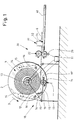
- a system for producing a rotor blade belt 1 from layers 6 of pultruded rods is shown schematically.
- the layers 6 of pultruded rods are made available on rod storage rolls 2, on which the rod layers 4 are rolled up, which are then later unrolled into rod layers 6.
- the rod storage roll 2 rests rotatably on a holding device 10 which has a frame 12 for holding the rod storage reel 2.
- a drive and braking device 13 is also arranged on the frame 12, by means of which the bar support roller 2 can be rotated in the unwinding direction 3, for example.
- the holding device 10 has at least one pressure roller 14 with a soft surface, which is arranged on an articulated pressure arm 15 which is acted upon by force by means of a spring 16.
- the pressure roller 14 thus presses in the direction 17 of the spring force against the rolled-up bar layer 4 and thus prevents it from unrolling under its own spiral spring force.
- the pressure roller 14 is arranged where the rolled-up bar support 4 is unrolled.
- further pressure rollers 14, which can also be subjected to spring force, can be arranged around the circumference of the bar support 4.
- the bar support 4 is unrolled and guided through a guide device 20 with two guide rollers 22. This picks up the bar support 4 and forwards it to a trimming device 30, which can have milling and / or sawing devices in order to define the end edge of a bar support 6.
- the bar tray 6 is further unrolled and placed in the desired position on a laminating form 40 or inserted into it.
- a control device 11 which can receive signals via signal channels shown in dashed lines, which can be wired or wireless, from sensors 19, 19 ', 29, which the control device 11 inform about the progress of the unrolling.
- sensors 19, 19 ′, 29 can for example be sensors 19 which are arranged on a force application device, for example a spring, with which a pressure roller 14 is applied.
- a sensor 19 ′ can also be arranged directly on a pressure roller 14.
- An alternative or additional sensor 29 can also monitor the progress of the unwinding on a guide roller 22.
- Such a sensor 29 can be a contactless sensor or, for example, also a rotary wheel or impeller.
- the control device 11 also has a control channel, wireless or wired, to the drive and braking device 13 of the holding device 10.
- a driven guide wheel 22 can also be controlled in the same way, so that a preprogrammed contour of the rotor blade belt to be built can be set automatically.
- the height of the guide rollers 22 or the guide device 20 can also be adjusted in order to successively adapt the height reached during the construction of the rotor blade belt from successive layers 6 of pultruded rods.
- the trimming device 30 is shown with a dust-tight encapsulation 32, which also has a connection 34 for suctioning off any dust that occurs. In this way, the trimming is carried out largely without dust.
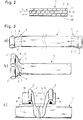
- Fig. 2 the layer structure of a rotor blade belt produced according to the invention is shown schematically.
- the cross section shows the lamination mold 40 at the bottom, on which three layers 6, 6 'of pultruded rods 7, 8 are arranged.
- Each layer 6, 6 ' has a multiplicity of normal width pultruded rods 7 and in each case a lateral pultruded rod 8 of smaller width, in particular half Width, on.
- the latter are in layers 6 in Fig.
- Fig. 3a), 3b) and 3c are three alternatives for making the in Fig. 2 shown structure of a rotor blade belt 1 is shown.
- layers 6, 6 ' are alternately deposited from the end on the leaf root side and from the end on the blade tip side of two rod layer rolls 2, 2' in opposite directions according to the direction of the arrow.
- the layers 6 have the bars 8 of reduced width on one side, the bar roll 2 'on the opposite side, so that the structure is from Fig. 2 results.
- roller 2 it is also possible to mount only one roller 2 'on the carriage 18, but to mount it so that it can be rotated about a vertical axis perpendicular to the surface of the laminating mold.
- the roller 2 can thus be rotated in such a way that it alternately assumes the different required orientations, depending on the direction in which the carriage 18 is moved.
Landscapes
- Engineering & Computer Science (AREA)
- Mechanical Engineering (AREA)
- Moulding By Coating Moulds (AREA)
- Casting Or Compression Moulding Of Plastics Or The Like (AREA)
- Extrusion Moulding Of Plastics Or The Like (AREA)
- Chemical & Material Sciences (AREA)
- Composite Materials (AREA)
Applications Claiming Priority (2)
| Application Number | Priority Date | Filing Date | Title |
|---|---|---|---|
| DE102012219224.7A DE102012219224B3 (de) | 2012-10-22 | 2012-10-22 | System und Verfahren zum Herstellen eines Rotorblattgurtes |
| PCT/EP2013/003007 WO2014063783A1 (de) | 2012-10-22 | 2013-10-07 | System and verfahren zum herstellen eines rotorblattgurtes |
Publications (2)
| Publication Number | Publication Date |
|---|---|
| EP2909015A1 EP2909015A1 (de) | 2015-08-26 |
| EP2909015B1 true EP2909015B1 (de) | 2021-12-01 |
Family
ID=49486432
Family Applications (1)
| Application Number | Title | Priority Date | Filing Date |
|---|---|---|---|
| EP13782961.0A Active EP2909015B1 (de) | 2012-10-22 | 2013-10-07 | System und verfahren zum herstellen eines rotorblattgurtes |
Country Status (13)
| Country | Link |
|---|---|
| US (1) | US9849658B2 (da) |
| EP (1) | EP2909015B1 (da) |
| KR (1) | KR101814409B1 (da) |
| CN (1) | CN104968486B (da) |
| AU (1) | AU2013337091B2 (da) |
| CA (1) | CA2886809C (da) |
| DE (1) | DE102012219224B3 (da) |
| DK (1) | DK2909015T3 (da) |
| ES (1) | ES2902849T3 (da) |
| IN (1) | IN2015DN03966A (da) |
| PT (1) | PT2909015T (da) |
| WO (1) | WO2014063783A1 (da) |
| ZA (1) | ZA201503122B (da) |
Families Citing this family (25)
| Publication number | Priority date | Publication date | Assignee | Title |
|---|---|---|---|---|
| DE102014018498A1 (de) * | 2014-12-16 | 2016-06-16 | Senvion Gmbh | Anordnung pultrudierter Stäbe |
| DE102015007289A1 (de) * | 2015-06-10 | 2016-12-15 | Senvion Gmbh | Rotorblatt, Rotorblattgurt und Verfahren zum Herstellen eines Rotorblattgurts |
| US10337490B2 (en) | 2015-06-29 | 2019-07-02 | General Electric Company | Structural component for a modular rotor blade |
| US9897065B2 (en) | 2015-06-29 | 2018-02-20 | General Electric Company | Modular wind turbine rotor blades and methods of assembling same |
| US10077758B2 (en) | 2015-06-30 | 2018-09-18 | General Electric Company | Corrugated pre-cured laminate plates for use within wind turbine rotor blades |
| US10072632B2 (en) | 2015-06-30 | 2018-09-11 | General Electric Company | Spar cap for a wind turbine rotor blade formed from pre-cured laminate plates of varying thicknesses |
| US9951750B2 (en) | 2015-07-30 | 2018-04-24 | General Electric Company | Rotor blade with interior shelf for a flat plate spar cap |
| US10422315B2 (en) | 2015-09-01 | 2019-09-24 | General Electric Company | Pultruded components for a shear web of a wind turbine rotor blade |
| US10584678B2 (en) | 2015-09-01 | 2020-03-10 | General Electric Company | Shear web for a wind turbine rotor blade |
| US10669984B2 (en) | 2015-09-22 | 2020-06-02 | General Electric Company | Method for manufacturing blade components using pre-cured laminate materials |
| US10107257B2 (en) | 2015-09-23 | 2018-10-23 | General Electric Company | Wind turbine rotor blade components formed from pultruded hybrid-resin fiber-reinforced composites |
| US10113532B2 (en) | 2015-10-23 | 2018-10-30 | General Electric Company | Pre-cured composites for rotor blade components |
| DE102016000134A1 (de) * | 2016-01-11 | 2017-07-13 | Carbon Rotec Gmbh & Co. Kg | Vorrichtung zum Besäumen, insbesondere von Rändern an Windrotorflügel-Teilen |
| DE102016108785A1 (de) * | 2016-05-12 | 2017-11-16 | Wobben Properties Gmbh | Verfahren zum Trennen eines trockenen Faserverbundgeleges, Verwendung einer Trennvorrichtung zum Trennen eines trockenen Faserverbundgeleges und eine Windenergieanlage |
| US10422316B2 (en) | 2016-08-30 | 2019-09-24 | General Electric Company | Pre-cured rotor blade components having areas of variable stiffness |
| DE102016013064A1 (de) * | 2016-11-03 | 2018-05-03 | Senvion Gmbh | Rotorblatt mit gekrümmten Pultrudaten |
| US10738759B2 (en) | 2017-02-09 | 2020-08-11 | General Electric Company | Methods for manufacturing spar caps for wind turbine rotor blades |
| US10527023B2 (en) | 2017-02-09 | 2020-01-07 | General Electric Company | Methods for manufacturing spar caps for wind turbine rotor blades |
| CN106985410A (zh) * | 2017-05-10 | 2017-07-28 | 常州市新创复合材料有限公司 | 采用拉挤成型的板材制作风电叶片大梁或辅梁的生产系统 |
| US10677216B2 (en) | 2017-10-24 | 2020-06-09 | General Electric Company | Wind turbine rotor blade components formed using pultruded rods |
| US11738530B2 (en) | 2018-03-22 | 2023-08-29 | General Electric Company | Methods for manufacturing wind turbine rotor blade components |
| DE102019001242A1 (de) * | 2019-02-21 | 2020-08-27 | Senvion Gmbh | Verfahren zur Herstellung geschäfteter Faserverbundelemente und eine Besäumvorrichtung zur Durchführung des Verfahrens |
| CN114072263B (zh) | 2019-07-16 | 2024-06-21 | Lm风力发电公司 | 制造在风力涡轮转子叶片部件中使用的面板的系统和方法 |
| CN114072264B (zh) | 2019-07-16 | 2024-06-21 | Lm风力发电公司 | 制造在风力涡轮转子叶片部件中使用的面板的系统和方法 |
| KR102363931B1 (ko) * | 2020-11-27 | 2022-02-16 | (주)휴먼컴퍼지트 | 대형 풍력 복합재 블레이드의 스파캡 소재 자동 적층 시스템 |
Citations (1)
| Publication number | Priority date | Publication date | Assignee | Title |
|---|---|---|---|---|
| US20180297308A1 (en) * | 2007-11-09 | 2018-10-18 | Vestas Wind Systems A/S | Structural mat for reinforcing a wind turbine blade structure, a wind turbine blade and a method for manufacturing a wind turbine blade |
Family Cites Families (16)
| Publication number | Priority date | Publication date | Assignee | Title |
|---|---|---|---|---|
| JPS58185217A (ja) * | 1982-04-26 | 1983-10-28 | Komatsu Kasei Kk | 風車翼の製造方法 |
| US5375324A (en) | 1993-07-12 | 1994-12-27 | Flowind Corporation | Vertical axis wind turbine with pultruded blades |
| CN1975152B (zh) | 2001-07-19 | 2012-03-21 | 维斯塔斯风力系统集团公司 | 风力涡轮机叶片 |
| DE10336461A1 (de) | 2003-08-05 | 2005-03-03 | Aloys Wobben | Verfahren zur Herstellung eines Rotorblattes einer Windenergieanlage |
| US7341086B2 (en) | 2004-10-29 | 2008-03-11 | The Boeing Company | Automated fabric layup system and method |
| CN101137841B (zh) * | 2005-02-03 | 2013-01-09 | 维斯塔斯风力系统有限公司 | 制造风轮机叶片壳体构件的方法 |
| CN102308083B (zh) * | 2008-12-05 | 2016-04-13 | 模组风能公司 | 高效风轮机叶片 |
| WO2010129492A2 (en) | 2009-05-04 | 2010-11-11 | Lamb Assembly And Test, Llc | Rapid material placement application for wind turbine blade manufacture |
| EP2228198A1 (en) * | 2009-05-18 | 2010-09-15 | Lm Glasfiber A/S | A method of strengthening a wind turbine blade and the strengthened blade |
| ES2365571B1 (es) | 2009-05-21 | 2012-09-17 | Danobat S.Coop | Sistema para la fabricacion automatica de palas de aerogenerador |
| US20110135485A1 (en) | 2009-12-30 | 2011-06-09 | Jing Wang | Spar for a wind turbine rotor blade and method for fabricating the same |
| MX341495B (es) * | 2010-01-14 | 2016-08-23 | Neptco Inc * | Componentes de pala de rotor de turbina eolica y metodos para la fabricacion de los mismos. |
| BR112013003473A2 (pt) | 2010-08-17 | 2019-09-24 | Zoltek Companies Inc | carro para aplicar uma folha contínua impregnada com resina à superfície contornada de uma tampa de mastro de ferramenta de moldagem |
| US8250761B2 (en) * | 2010-12-13 | 2012-08-28 | General Electric Company | Methods of manufacturing rotor blades for a wind turbine |
| US20120027609A1 (en) * | 2011-05-17 | 2012-02-02 | Prasad Ogde | Wind turbine rotor blade with precured fiber rods and method for producing the same |
| GB2497578B (en) * | 2011-12-16 | 2015-01-14 | Vestas Wind Sys As | Wind turbine blades |
-
2012
- 2012-10-22 DE DE102012219224.7A patent/DE102012219224B3/de active Active
-
2013
- 2013-10-07 EP EP13782961.0A patent/EP2909015B1/de active Active
- 2013-10-07 PT PT137829610T patent/PT2909015T/pt unknown
- 2013-10-07 ES ES13782961T patent/ES2902849T3/es active Active
- 2013-10-07 AU AU2013337091A patent/AU2013337091B2/en not_active Ceased
- 2013-10-07 KR KR1020157013513A patent/KR101814409B1/ko not_active Expired - Fee Related
- 2013-10-07 WO PCT/EP2013/003007 patent/WO2014063783A1/de not_active Ceased
- 2013-10-07 CN CN201380061105.1A patent/CN104968486B/zh active Active
- 2013-10-07 CA CA2886809A patent/CA2886809C/en not_active Expired - Fee Related
- 2013-10-07 IN IN3966DEN2015 patent/IN2015DN03966A/en unknown
- 2013-10-07 DK DK13782961.0T patent/DK2909015T3/da active
-
2015
- 2015-04-21 US US14/692,684 patent/US9849658B2/en active Active
- 2015-05-07 ZA ZA2015/03122A patent/ZA201503122B/en unknown
Patent Citations (1)
| Publication number | Priority date | Publication date | Assignee | Title |
|---|---|---|---|---|
| US20180297308A1 (en) * | 2007-11-09 | 2018-10-18 | Vestas Wind Systems A/S | Structural mat for reinforcing a wind turbine blade structure, a wind turbine blade and a method for manufacturing a wind turbine blade |
Also Published As
| Publication number | Publication date |
|---|---|
| EP2909015A1 (de) | 2015-08-26 |
| IN2015DN03966A (da) | 2015-10-02 |
| KR20150081300A (ko) | 2015-07-13 |
| WO2014063783A1 (de) | 2014-05-01 |
| ZA201503122B (en) | 2016-01-27 |
| CA2886809A1 (en) | 2014-05-01 |
| CA2886809C (en) | 2017-08-15 |
| PT2909015T (pt) | 2021-12-28 |
| CN104968486B (zh) | 2017-08-08 |
| CN104968486A (zh) | 2015-10-07 |
| KR101814409B1 (ko) | 2018-01-03 |
| AU2013337091B2 (en) | 2016-05-19 |
| DE102012219224B3 (de) | 2014-03-27 |
| US9849658B2 (en) | 2017-12-26 |
| ES2902849T3 (es) | 2022-03-30 |
| DK2909015T3 (da) | 2022-02-07 |
| AU2013337091A1 (en) | 2015-06-11 |
| US20150224760A1 (en) | 2015-08-13 |
Similar Documents
| Publication | Publication Date | Title |
|---|---|---|
| EP2909015B1 (de) | System und verfahren zum herstellen eines rotorblattgurtes | |
| EP2265436B1 (de) | Verfahren zur herstellung eines profilierten preforms oder eines profilierten fvk-bauteils | |
| EP3496936B1 (de) | Gurt aus vorgefertigten elementen mit gelege und ein verfahren zu seiner fertigung | |
| DE3341564C2 (da) | ||
| EP2363599B1 (de) | Rotorblatt für eine Windenergieanlage, Windenergieanlage und Verfahren zum Herstellen eines Rotorblatts | |
| EP2917020B1 (de) | Vorrichtung und verfahren zum herstellen von halbzeugen fuer windenergieanlagen-rotorblaetter | |
| EP3678851B1 (de) | Fertigungsanlage und verfahren zum legen von faserbändern | |
| DE102009003421A1 (de) | Rotorflügel einer Windkraftanlage und Verfahren zur Herstellung desselben | |
| EP2729295B1 (de) | Verklebeeinrichtung zum bau von segmentierten rotorblättern | |
| WO2013007351A1 (de) | Verfahren zum herstellen eines rotorblatts für eine windenergieanlage, sandwich-preform und rotorblatt für eine windenergieanlage | |
| WO2010003494A1 (de) | Verfahren und vorrichtung zur herstellung eines ringförmigen vorformlings aus fasermaterialhalbzeug, sowie verwendung derartiger verfahren und vorrichtungen | |
| DE102008011517A1 (de) | Verfahren, Vorrichtung und Stützstruktur sowie deren Verwendung zur Herstellung eines Faserverbundteils | |
| EP2841257B1 (de) | Vorrichtung zum legen von folienförmigen material | |
| EP3551438B1 (de) | Hinterkantengurt eines rotorblatts einer windenergieanlage, rotorblatt und verfahren zum herstellen eines hinterkantengurts | |
| EP3268197B1 (de) | Verfahren zum herstellen eines vorformlings | |
| EP3124661B1 (de) | Dynamisches aufspreizen von endlosfaserbündeln während eines herstellungsprozesses | |
| EP3366451B1 (de) | Folienmaschine und verfahren zur herstellung von stretchfolien | |
| DE102007015516B4 (de) | Kunststoff-Faser-Verbundbauteil in Form eines Profils mit über die Länge variierendem Profilquerschnitt | |
| DE102009057009B4 (de) | Vorrichtung und Verfahren zur Herstellung eines schalenförmigen Verbundbauteils | |
| WO1996026887A1 (de) | Teleskopausleger, insbesondere für hubarbeitsbühnen, sowie verfahren und mittel zur herstellung zylindrischer rohrförmiger teleskopschüsse | |
| EP3360671B1 (de) | Drehbare teilvorform für einen preform | |
| DE102013204635A1 (de) | Vorrichtung und Verfahren zum Herstellen von Halbzeugen für Windenergieanlagen-Rotorblätter, sowie Rotorblatt und Windenergieanlage hiermit | |
| EP0515952A2 (de) | Verfahren zum Herstellen von Pfeilerverschalungen | |
| EP2648887B1 (de) | Verfahren und vorrichtung zum herstellen eines holmkastens für ein rotorblatt, holmkasten | |
| AT512832B1 (de) | Wechselmagazin für eine Vorrichtung zum Legen von folienförmigem Material |
Legal Events
| Date | Code | Title | Description |
|---|---|---|---|
| PUAI | Public reference made under article 153(3) epc to a published international application that has entered the european phase |
Free format text: ORIGINAL CODE: 0009012 |
|
| 17P | Request for examination filed |
Effective date: 20150318 |
|
| AK | Designated contracting states |
Kind code of ref document: A1 Designated state(s): AL AT BE BG CH CY CZ DE DK EE ES FI FR GB GR HR HU IE IS IT LI LT LU LV MC MK MT NL NO PL PT RO RS SE SI SK SM TR |
|
| AX | Request for extension of the european patent |
Extension state: BA ME |
|
| RAP1 | Party data changed (applicant data changed or rights of an application transferred) |
Owner name: SENVION GMBH |
|
| DAX | Request for extension of the european patent (deleted) | ||
| STAA | Information on the status of an ep patent application or granted ep patent |
Free format text: STATUS: EXAMINATION IS IN PROGRESS |
|
| 17Q | First examination report despatched |
Effective date: 20190625 |
|
| GRAP | Despatch of communication of intention to grant a patent |
Free format text: ORIGINAL CODE: EPIDOSNIGR1 |
|
| STAA | Information on the status of an ep patent application or granted ep patent |
Free format text: STATUS: GRANT OF PATENT IS INTENDED |
|
| INTG | Intention to grant announced |
Effective date: 20210527 |
|
| RAP1 | Party data changed (applicant data changed or rights of an application transferred) |
Owner name: SIEMENS GAMESA RENEWABLE ENERGY SERVICE GMBH |
|
| GRAS | Grant fee paid |
Free format text: ORIGINAL CODE: EPIDOSNIGR3 |
|
| GRAA | (expected) grant |
Free format text: ORIGINAL CODE: 0009210 |
|
| STAA | Information on the status of an ep patent application or granted ep patent |
Free format text: STATUS: THE PATENT HAS BEEN GRANTED |
|
| AK | Designated contracting states |
Kind code of ref document: B1 Designated state(s): AL AT BE BG CH CY CZ DE DK EE ES FI FR GB GR HR HU IE IS IT LI LT LU LV MC MK MT NL NO PL PT RO RS SE SI SK SM TR |
|
| REG | Reference to a national code |
Ref country code: GB Ref legal event code: FG4D Free format text: NOT ENGLISH |
|
| REG | Reference to a national code |
Ref country code: AT Ref legal event code: REF Ref document number: 1451355 Country of ref document: AT Kind code of ref document: T Effective date: 20211215 Ref country code: CH Ref legal event code: EP |
|
| REG | Reference to a national code |
Ref country code: IE Ref legal event code: FG4D Free format text: LANGUAGE OF EP DOCUMENT: GERMAN |
|
| REG | Reference to a national code |
Ref country code: DE Ref legal event code: R096 Ref document number: 502013016002 Country of ref document: DE |
|
| REG | Reference to a national code |
Ref country code: PT Ref legal event code: SC4A Ref document number: 2909015 Country of ref document: PT Date of ref document: 20211228 Kind code of ref document: T Free format text: AVAILABILITY OF NATIONAL TRANSLATION Effective date: 20211220 |
|
| REG | Reference to a national code |
Ref country code: DK Ref legal event code: T3 Effective date: 20220131 |
|
| RAP4 | Party data changed (patent owner data changed or rights of a patent transferred) |
Owner name: SIEMENS GAMESA RENEWABLE ENERGY SERVICE GMBH |
|
| REG | Reference to a national code |
Ref country code: LT Ref legal event code: MG9D |
|
| REG | Reference to a national code |
Ref country code: ES Ref legal event code: FG2A Ref document number: 2902849 Country of ref document: ES Kind code of ref document: T3 Effective date: 20220330 |
|
| REG | Reference to a national code |
Ref country code: NL Ref legal event code: MP Effective date: 20211201 |
|
| PG25 | Lapsed in a contracting state [announced via postgrant information from national office to epo] |
Ref country code: RS Free format text: LAPSE BECAUSE OF FAILURE TO SUBMIT A TRANSLATION OF THE DESCRIPTION OR TO PAY THE FEE WITHIN THE PRESCRIBED TIME-LIMIT Effective date: 20211201 Ref country code: LT Free format text: LAPSE BECAUSE OF FAILURE TO SUBMIT A TRANSLATION OF THE DESCRIPTION OR TO PAY THE FEE WITHIN THE PRESCRIBED TIME-LIMIT Effective date: 20211201 Ref country code: FI Free format text: LAPSE BECAUSE OF FAILURE TO SUBMIT A TRANSLATION OF THE DESCRIPTION OR TO PAY THE FEE WITHIN THE PRESCRIBED TIME-LIMIT Effective date: 20211201 Ref country code: BG Free format text: LAPSE BECAUSE OF FAILURE TO SUBMIT A TRANSLATION OF THE DESCRIPTION OR TO PAY THE FEE WITHIN THE PRESCRIBED TIME-LIMIT Effective date: 20220301 |
|
| PG25 | Lapsed in a contracting state [announced via postgrant information from national office to epo] |
Ref country code: SE Free format text: LAPSE BECAUSE OF FAILURE TO SUBMIT A TRANSLATION OF THE DESCRIPTION OR TO PAY THE FEE WITHIN THE PRESCRIBED TIME-LIMIT Effective date: 20211201 Ref country code: PL Free format text: LAPSE BECAUSE OF FAILURE TO SUBMIT A TRANSLATION OF THE DESCRIPTION OR TO PAY THE FEE WITHIN THE PRESCRIBED TIME-LIMIT Effective date: 20211201 Ref country code: NO Free format text: LAPSE BECAUSE OF FAILURE TO SUBMIT A TRANSLATION OF THE DESCRIPTION OR TO PAY THE FEE WITHIN THE PRESCRIBED TIME-LIMIT Effective date: 20220301 Ref country code: LV Free format text: LAPSE BECAUSE OF FAILURE TO SUBMIT A TRANSLATION OF THE DESCRIPTION OR TO PAY THE FEE WITHIN THE PRESCRIBED TIME-LIMIT Effective date: 20211201 Ref country code: HR Free format text: LAPSE BECAUSE OF FAILURE TO SUBMIT A TRANSLATION OF THE DESCRIPTION OR TO PAY THE FEE WITHIN THE PRESCRIBED TIME-LIMIT Effective date: 20211201 Ref country code: GR Free format text: LAPSE BECAUSE OF FAILURE TO SUBMIT A TRANSLATION OF THE DESCRIPTION OR TO PAY THE FEE WITHIN THE PRESCRIBED TIME-LIMIT Effective date: 20220302 |
|
| PG25 | Lapsed in a contracting state [announced via postgrant information from national office to epo] |
Ref country code: NL Free format text: LAPSE BECAUSE OF FAILURE TO SUBMIT A TRANSLATION OF THE DESCRIPTION OR TO PAY THE FEE WITHIN THE PRESCRIBED TIME-LIMIT Effective date: 20211201 |
|
| PG25 | Lapsed in a contracting state [announced via postgrant information from national office to epo] |
Ref country code: SM Free format text: LAPSE BECAUSE OF FAILURE TO SUBMIT A TRANSLATION OF THE DESCRIPTION OR TO PAY THE FEE WITHIN THE PRESCRIBED TIME-LIMIT Effective date: 20211201 Ref country code: SK Free format text: LAPSE BECAUSE OF FAILURE TO SUBMIT A TRANSLATION OF THE DESCRIPTION OR TO PAY THE FEE WITHIN THE PRESCRIBED TIME-LIMIT Effective date: 20211201 Ref country code: RO Free format text: LAPSE BECAUSE OF FAILURE TO SUBMIT A TRANSLATION OF THE DESCRIPTION OR TO PAY THE FEE WITHIN THE PRESCRIBED TIME-LIMIT Effective date: 20211201 Ref country code: EE Free format text: LAPSE BECAUSE OF FAILURE TO SUBMIT A TRANSLATION OF THE DESCRIPTION OR TO PAY THE FEE WITHIN THE PRESCRIBED TIME-LIMIT Effective date: 20211201 Ref country code: CZ Free format text: LAPSE BECAUSE OF FAILURE TO SUBMIT A TRANSLATION OF THE DESCRIPTION OR TO PAY THE FEE WITHIN THE PRESCRIBED TIME-LIMIT Effective date: 20211201 |
|
| REG | Reference to a national code |
Ref country code: DE Ref legal event code: R097 Ref document number: 502013016002 Country of ref document: DE |
|
| PG25 | Lapsed in a contracting state [announced via postgrant information from national office to epo] |
Ref country code: IS Free format text: LAPSE BECAUSE OF FAILURE TO SUBMIT A TRANSLATION OF THE DESCRIPTION OR TO PAY THE FEE WITHIN THE PRESCRIBED TIME-LIMIT Effective date: 20220401 |
|
| PLBE | No opposition filed within time limit |
Free format text: ORIGINAL CODE: 0009261 |
|
| STAA | Information on the status of an ep patent application or granted ep patent |
Free format text: STATUS: NO OPPOSITION FILED WITHIN TIME LIMIT |
|
| PG25 | Lapsed in a contracting state [announced via postgrant information from national office to epo] |
Ref country code: AL Free format text: LAPSE BECAUSE OF FAILURE TO SUBMIT A TRANSLATION OF THE DESCRIPTION OR TO PAY THE FEE WITHIN THE PRESCRIBED TIME-LIMIT Effective date: 20211201 |
|
| 26N | No opposition filed |
Effective date: 20220902 |
|
| PG25 | Lapsed in a contracting state [announced via postgrant information from national office to epo] |
Ref country code: SI Free format text: LAPSE BECAUSE OF FAILURE TO SUBMIT A TRANSLATION OF THE DESCRIPTION OR TO PAY THE FEE WITHIN THE PRESCRIBED TIME-LIMIT Effective date: 20211201 |
|
| PG25 | Lapsed in a contracting state [announced via postgrant information from national office to epo] |
Ref country code: MC Free format text: LAPSE BECAUSE OF FAILURE TO SUBMIT A TRANSLATION OF THE DESCRIPTION OR TO PAY THE FEE WITHIN THE PRESCRIBED TIME-LIMIT Effective date: 20211201 Ref country code: IT Free format text: LAPSE BECAUSE OF FAILURE TO SUBMIT A TRANSLATION OF THE DESCRIPTION OR TO PAY THE FEE WITHIN THE PRESCRIBED TIME-LIMIT Effective date: 20211201 |
|
| REG | Reference to a national code |
Ref country code: CH Ref legal event code: PL |
|
| REG | Reference to a national code |
Ref country code: BE Ref legal event code: MM Effective date: 20221031 |
|
| PG25 | Lapsed in a contracting state [announced via postgrant information from national office to epo] |
Ref country code: LU Free format text: LAPSE BECAUSE OF NON-PAYMENT OF DUE FEES Effective date: 20221007 |
|
| PG25 | Lapsed in a contracting state [announced via postgrant information from national office to epo] |
Ref country code: LI Free format text: LAPSE BECAUSE OF NON-PAYMENT OF DUE FEES Effective date: 20221031 Ref country code: CH Free format text: LAPSE BECAUSE OF NON-PAYMENT OF DUE FEES Effective date: 20221031 |
|
| PG25 | Lapsed in a contracting state [announced via postgrant information from national office to epo] |
Ref country code: BE Free format text: LAPSE BECAUSE OF NON-PAYMENT OF DUE FEES Effective date: 20221031 |
|
| PG25 | Lapsed in a contracting state [announced via postgrant information from national office to epo] |
Ref country code: IE Free format text: LAPSE BECAUSE OF NON-PAYMENT OF DUE FEES Effective date: 20221007 |
|
| REG | Reference to a national code |
Ref country code: AT Ref legal event code: MM01 Ref document number: 1451355 Country of ref document: AT Kind code of ref document: T Effective date: 20221007 |
|
| PG25 | Lapsed in a contracting state [announced via postgrant information from national office to epo] |
Ref country code: AT Free format text: LAPSE BECAUSE OF NON-PAYMENT OF DUE FEES Effective date: 20221007 |
|
| PG25 | Lapsed in a contracting state [announced via postgrant information from national office to epo] |
Ref country code: HU Free format text: LAPSE BECAUSE OF FAILURE TO SUBMIT A TRANSLATION OF THE DESCRIPTION OR TO PAY THE FEE WITHIN THE PRESCRIBED TIME-LIMIT; INVALID AB INITIO Effective date: 20131007 |
|
| PG25 | Lapsed in a contracting state [announced via postgrant information from national office to epo] |
Ref country code: CY Free format text: LAPSE BECAUSE OF FAILURE TO SUBMIT A TRANSLATION OF THE DESCRIPTION OR TO PAY THE FEE WITHIN THE PRESCRIBED TIME-LIMIT Effective date: 20211201 |
|
| PG25 | Lapsed in a contracting state [announced via postgrant information from national office to epo] |
Ref country code: MK Free format text: LAPSE BECAUSE OF FAILURE TO SUBMIT A TRANSLATION OF THE DESCRIPTION OR TO PAY THE FEE WITHIN THE PRESCRIBED TIME-LIMIT Effective date: 20211201 |
|
| PG25 | Lapsed in a contracting state [announced via postgrant information from national office to epo] |
Ref country code: MT Free format text: LAPSE BECAUSE OF FAILURE TO SUBMIT A TRANSLATION OF THE DESCRIPTION OR TO PAY THE FEE WITHIN THE PRESCRIBED TIME-LIMIT Effective date: 20211201 |
|
| PGFP | Annual fee paid to national office [announced via postgrant information from national office to epo] |
Ref country code: FR Payment date: 20241025 Year of fee payment: 12 |
|
| PGFP | Annual fee paid to national office [announced via postgrant information from national office to epo] |
Ref country code: ES Payment date: 20241118 Year of fee payment: 12 |
|
| PGFP | Annual fee paid to national office [announced via postgrant information from national office to epo] |
Ref country code: PT Payment date: 20250916 Year of fee payment: 13 |
|
| PGFP | Annual fee paid to national office [announced via postgrant information from national office to epo] |
Ref country code: DK Payment date: 20250901 Year of fee payment: 13 |
|
| PGFP | Annual fee paid to national office [announced via postgrant information from national office to epo] |
Ref country code: GB Payment date: 20250901 Year of fee payment: 13 |
|
| PG25 | Lapsed in a contracting state [announced via postgrant information from national office to epo] |
Ref country code: TR Free format text: LAPSE BECAUSE OF FAILURE TO SUBMIT A TRANSLATION OF THE DESCRIPTION OR TO PAY THE FEE WITHIN THE PRESCRIBED TIME-LIMIT Effective date: 20211201 |
|
| PGFP | Annual fee paid to national office [announced via postgrant information from national office to epo] |
Ref country code: DE Payment date: 20250731 Year of fee payment: 13 |