EP2909033B1 - Presse d'impression en héliogravure et procédé de surveillance de fonctionnement de celle-ci - Google Patents
Presse d'impression en héliogravure et procédé de surveillance de fonctionnement de celle-ci Download PDFInfo
- Publication number
- EP2909033B1 EP2909033B1 EP13792492.4A EP13792492A EP2909033B1 EP 2909033 B1 EP2909033 B1 EP 2909033B1 EP 13792492 A EP13792492 A EP 13792492A EP 2909033 B1 EP2909033 B1 EP 2909033B1
- Authority
- EP
- European Patent Office
- Prior art keywords
- cylinder
- plate cylinder
- gear
- impression
- impression cylinder
- Prior art date
- Legal status (The legal status is an assumption and is not a legal conclusion. Google has not performed a legal analysis and makes no representation as to the accuracy of the status listed.)
- Not-in-force
Links
Images




Classifications
-
- B—PERFORMING OPERATIONS; TRANSPORTING
- B41—PRINTING; LINING MACHINES; TYPEWRITERS; STAMPS
- B41F—PRINTING MACHINES OR PRESSES
- B41F33/00—Indicating, counting, warning, control or safety devices
- B41F33/0072—Devices for measuring the pressure between cylinders or bearer rings
-
- B—PERFORMING OPERATIONS; TRANSPORTING
- B41—PRINTING; LINING MACHINES; TYPEWRITERS; STAMPS
- B41F—PRINTING MACHINES OR PRESSES
- B41F33/00—Indicating, counting, warning, control or safety devices
- B41F33/0009—Central control units
-
- B—PERFORMING OPERATIONS; TRANSPORTING
- B41—PRINTING; LINING MACHINES; TYPEWRITERS; STAMPS
- B41F—PRINTING MACHINES OR PRESSES
- B41F11/00—Rotary presses or machines having forme cylinders carrying a plurality of printing surfaces, or for performing letterpress, lithographic, or intaglio processes selectively or in combination
- B41F11/02—Rotary presses or machines having forme cylinders carrying a plurality of printing surfaces, or for performing letterpress, lithographic, or intaglio processes selectively or in combination for securities
-
- B—PERFORMING OPERATIONS; TRANSPORTING
- B41—PRINTING; LINING MACHINES; TYPEWRITERS; STAMPS
- B41F—PRINTING MACHINES OR PRESSES
- B41F13/00—Common details of rotary presses or machines
- B41F13/08—Cylinders
- B41F13/24—Cylinder-tripping devices; Cylinder-impression adjustments
-
- B—PERFORMING OPERATIONS; TRANSPORTING
- B41—PRINTING; LINING MACHINES; TYPEWRITERS; STAMPS
- B41F—PRINTING MACHINES OR PRESSES
- B41F33/00—Indicating, counting, warning, control or safety devices
-
- B—PERFORMING OPERATIONS; TRANSPORTING
- B41—PRINTING; LINING MACHINES; TYPEWRITERS; STAMPS
- B41F—PRINTING MACHINES OR PRESSES
- B41F33/00—Indicating, counting, warning, control or safety devices
- B41F33/02—Arrangements of indicating devices, e.g. counters
-
- B—PERFORMING OPERATIONS; TRANSPORTING
- B41—PRINTING; LINING MACHINES; TYPEWRITERS; STAMPS
- B41F—PRINTING MACHINES OR PRESSES
- B41F9/00—Rotary intaglio printing presses
-
- B—PERFORMING OPERATIONS; TRANSPORTING
- B41—PRINTING; LINING MACHINES; TYPEWRITERS; STAMPS
- B41F—PRINTING MACHINES OR PRESSES
- B41F9/00—Rotary intaglio printing presses
- B41F9/02—Rotary intaglio printing presses for multicolour printing
- B41F9/021—Sheet printing presses
-
- B—PERFORMING OPERATIONS; TRANSPORTING
- B41—PRINTING; LINING MACHINES; TYPEWRITERS; STAMPS
- B41F—PRINTING MACHINES OR PRESSES
- B41F9/00—Rotary intaglio printing presses
- B41F9/06—Details
- B41F9/061—Inking devices
- B41F9/063—Using inking rollers
Definitions
- the present invention generally relates to intaglio printing, and more particularly to an intaglio printing press and a method of monitoring operation of the same.
- Intaglio printing presses are widely used in security printing for printing security documents, especially banknotes.
- Prior art intaglio printing presses are for instance disclosed in Swiss Patent No. CH 477 293 A5 , European Patent Publications Nos. EP 0 091 709 A1 , EP 0 406 157 A1 , EP 0 415 881 A2 , EP 0 563 007 A1 , EP 0 873 866 A1 , EP 1 602 483 A1 , and International Publications Nos.
- Figure 1 schematically illustrates an intaglio printing press which is generally designated by reference numeral 1. More precisely, Figure 1 shows a sheet-fed intaglio printing press 1 comprising a sheet feeder 2 for feeding sheets to be printed, an intaglio printing unit 3 for printing the sheets, and a sheet delivery unit 4 for collecting the freshly-printed sheets.
- a sheet-fed intaglio printing press 1 comprising a sheet feeder 2 for feeding sheets to be printed, an intaglio printing unit 3 for printing the sheets, and a sheet delivery unit 4 for collecting the freshly-printed sheets.
- the intaglio printing unit 3 includes an impression cylinder 7, a plate cylinder 8 (in this example, the plate cylinder 8 is a three-segment plate cylinder carrying three intaglio printing plates), an inking system comprising an ink-collecting cylinder, or Orlof cylinder, 9 (here a three-segment blanket cylinder carrying a corresponding number of blankets) for inking the surface of the intaglio printing plates carried by the plate cylinder 8 and an ink wiping system 10 for wiping the inked surface of the intaglio printing plates carried by the plate cylinder 8 prior to printing of the sheets.
- an impression cylinder 7 in this example, the plate cylinder 8 is a three-segment plate cylinder carrying three intaglio printing plates
- an inking system comprising an ink-collecting cylinder, or Orlof cylinder, 9 (here a three-segment blanket cylinder carrying a corresponding number of blankets) for inking the surface of the int
- the sheets are fed from the sheet feeder 2 onto a feeder table and then onto the impression cylinder 7.
- the sheets are then carried by the impression cylinder 7 to the printing nip between the impression cylinder 7 and the plate cylinder 8 where intaglio printing is performed.
- the sheets are transferred away from the impression cylinder 7 for conveyance by a sheet transporting system 15 in order to be delivered to the delivery unit 4.
- the sheet transporting system 15 conventionally comprises a sheet conveyor system with a pair of endless chains driving a plurality of spaced-apart gripper bars for holding a leading edge of the sheets (the freshly-printed side of the sheets being oriented downwards on their way to the delivery unit 4), sheets being transferred in succession to a corresponding one of the gripper bars.
- the optical inspection system 5 is advantageously an inspection system as disclosed in International Publication No. WO 2011/161656 A1 , which inspection system 5 comprises a transfer mechanism and an inspection drum located at the transfer section between the impression cylinder 7 and chain wheels of the sheet transporting system 15.
- the optical inspection system 5 could alternatively be an inspection system placed along the path of the sheet transporting system 15 as described in International Publications Nos. WO 97/36813 A1 , WO 97/37329 A1 , and WO 03/070465 A1 .
- Such inspection systems are in particular marketed by the Applicant under the product designation NotaSave®.
- the printed sheets are preferably transported in front of a drying or curing unit 6 disposed after the inspection system 5 along the transport path of the sheet transporting system 15. Drying or curing could possibly be performed prior to the optical inspection of the sheets.
- FIG 2 is a schematic view of the intaglio printing unit 3 of the intaglio printing press 1 of Figure 1 .
- the printing unit 3 basically includes the impression cylinder 7, the plate cylinder 8 with its intaglio printing plates, the inking system with its ink-collecting cylinder 9, and the ink wiping system 10.
- the inking system comprises in this example five inking devices 20, all of which cooperate with the ink-collecting cylinder 9 that contacts the plate cylinder 8. It will be understood that the illustrated inking system is adapted for indirect inking of the plate cylinder 8, i.e. inking of the intaglio printing plates via the ink-collecting cylinder 9.
- the inking devices 20 each include an ink duct 21 cooperating in this example with a pair of ink-application rollers 22.
- Each pair of ink-application rollers 22 in turn inks a corresponding chablon cylinder 23 which is in contact with the ink-collecting cylinder 9.
- the surface of the chablon cylinders 23 is structured so as to exhibit raised portions corresponding to the areas of the intaglio printing plates intended to receive the inks in the corresponding colours supplied by the respective inking devices 20.
- the impression cylinder 7 and plate cylinder 8 are both supported by a stationary (main) frame 50 of the printing press 1.
- the inking devices 20 (including the ink duct 21 and ink-application rollers 22) are supported in a mobile inking carriage 52, while the ink-collecting cylinder 9 and chablon cylinders 23 are supported in an intermediate carriage 51 located between the inking carriage 52 and the stationary frame 50. Both the inking carriage 52 and the intermediate carriage 51 are advantageously suspended under supporting rails.
- reference numeral 52' designates the inking carriage in a retracted position shown in dashed lines.
- twin-carriage configuration of the intaglio printing press 1 illustrated in Figures 1 and 2 corresponds in essence to the configuration disclosed in International Publications Nos. WO 03/047862 A1 , WO 2011/077348 A1 , WO 2011/077350 A1 and WO 2011/077351 A1 , all assigned to the present Applicant and which are incorporated herein by reference in their entirety.
- the ink wiping system 10 typically comprises a wiping tank, a wiping roller assembly 11 supported on and partly located in the wiping tank and contacting the plate cylinder 8, cleaning means (not shown) for removing wiped ink residues from the surface of the wiping roller assembly 11 using a wiping solution that is sprayed or otherwise applied onto the surface of the wiping roller assembly 11, and a drying blade (not shown) contacting the surface of the wiping roller assembly 11 for removing wiping solution residues from the surface of the wiping roller assembly 11.
- a particularly suitable solution for the ink wiping system 10 is disclosed in International Publication No. WO 2007/116353 A1 .
- intaglio printing presses as used for the production of security documents resides in the fact that very high printing pressures are applied at the printing nip between the plate cylinder and the impression cylinder, with line pressures in the range of 10'000 N/cm or more, i.e. more than 80 tons over the entire contact portion between the plate cylinder and the impression cylinder.
- line pressures in the range of 10'000 N/cm or more, i.e. more than 80 tons over the entire contact portion between the plate cylinder and the impression cylinder.
- a plate cylinder of an intaglio printing press typically consists of a cylinder base made of e.g. steel that carries one or more intaglio printing plates which are typically nickel plates (or any other suitable metal such as steel, brass or the like) whose surface is typically covered by a layer of wear-resistant material such as chromium (Cr).
- an impression cylinder of an intaglio printing press typically consists of a cylinder base made of e.g. steel which carries one or more impression blankets and one or more underlay sheets (or packing sheets) of e.g. paper or cardboard, the thickness of which is calibrated.
- the surface of the impression cylinder is typically compressed by the comparatively harder and more rigid surface of the plate cylinder, which leads to a local compression and deformation of the impression blanket and underlying packing sheets.
- the amount of compression and deformation depends on the pressure applied at the printing nip, but also on the nature and compressibility of the impression blanket and underlying packing sheets, as well as the relevant thickness of the intaglio printing plate(s) on the plate cylinder side and thickness of the impression blanket(s) and packing sheets on the impression cylinder side. It is to be further appreciated that the sheet material, which is held onto the circumference of the impression cylinder, is pressed at the printing nip between the plate cylinder and the impression cylinder.
- the plate cylinder and the impression cylinder of intaglio printing presses each commonly comprise one or more cylinder pits and a corresponding number of cylinder segments, the plate cylinder and the impression cylinder coming into rolling contact with one another along their respective cylinder segments when no cylinder pits are present at the printing nip.
- both the plate cylinder and the impression cylinder comprise three cylinder pits 8a, resp. 7a, and three cylinder segments 8b, resp. 7b each.
- Intaglio printing plates designated by reference 8c, are mounted on the circumference of the plate cylinder 8, namely on the three cylinder segments 8b, while three sets of impression blankets and packing sheets, jointly designated by reference 7c, are mounted on the circumference of the impression cylinder 7, namely on the three cylinder segments 7b.
- the plate cylinder and impression cylinder may however exhibit different numbers of cylinder pits and cylinder segments (as for instance disclosed in European Patent Publication No. EP 0 873 866 A1 ).
- intaglio printing units have to be very robust and be designed in such a way as to withstand the aforementioned huge forces and stresses that are generated during printing operations.
- multiple parameters may have an impact on the operation of the intaglio printing unit of intaglio printing presses and the resulting print quality, which parameters are dependent on operative settings made by the operator of the intaglio printing press.
- operative settings in particular include the amount of pressure applied at the printing nip during printing operations (which printing pressure is typically adjustable), the type and thickness of the intaglio printing plates, the type and thickness of the impression blankets, and the type, number and thickness of the underlying packing sheets.
- European Patent Publication No. EP 0 783 964 A1 merely discloses an intaglio printing press comprising means for adjusting the contact pressure between the impression cylinder and intaglio cylinder of the intaglio printing press.
- European Patent Publication No. EP 2 006 095 A2 merely discloses an intaglio printing press wherein the nip pressure (contact pressure) between various cylinders and/or rollers of the intaglio printing press can be adjusted automatically.
- the operating conditions change over time, especially as a result of the alteration of the structure and properties of the impression blankets and underlying packing sheets, as well as, to a certain extent, as a result of the deformation and elongation of the intaglio printing plates.
- a general aim of the invention is therefore to provide an improved intaglio printing press and an improved method of monitoring operation of an intaglio printing press.
- a further aim of the invention is to provide an intaglio printing press and a method of monitoring operation of the same which ensures optimum operation of the intaglio printing press within desired operating conditions, thereby reducing wear and improving the life-cycle expectancy of the intaglio printing press, as well as ensuring optimum printing conditions.
- Another aim of the invention is to provide such a solution that allows an operator to identify whether or not the intaglio printing press is being operated within desired operating conditions.
- an intaglio printing press comprising a plate cylinder carrying one or more intaglio printing plates and an impression cylinder cooperating with the plate cylinder, a printing nip being formed between the plate cylinder and the impression cylinder, the plate cylinder and the impression cylinder each comprising one or more cylinder pits and a corresponding number of cylinder segments, the plate cylinder and the impression cylinder being in rolling contact with one another during printing operations along their respective cylinder segments when no cylinder pits are present at the printing nip, wherein the intaglio printing press comprises a monitoring system designed to monitor a rolling condition of the impression cylinder with respect to the plate cylinder and to provide an indication as to whether or not the rolling condition corresponds to a desired rolling condition, the desired rolling condition being a rolling condition corresponding to true rolling of the impression cylinder with respect to the plate cylinder
- the monitoring system provides continuous or periodic measurements of a difference between a rotational position of the impression cylinder and a rotational position of the plate cylinder as the plate cylinder and the impression cylinder are in rolling contact with one another along their respective cylinder segments, and wherein an evolution of the difference between the rotational position of the impression cylinder and the rotational position of the plate cylinder as the plate cylinder and the impression cylinder are in rolling contact with one another along their respective cylinder segments is indicative of the rolling condition.
- the monitoring system may advantageously include a first rotary encoder providing a measurement of the rotational position of the plate cylinder, a second rotary encoder providing a measurement of the rotational position of the impression cylinder, and a processing unit computing the difference between the rotational position of the impression cylinder and the rotational position of the plate cylinder.
- a method of monitoring operation of an intaglio printing press comprising a plate cylinder carrying one or more intaglio printing plates and an impression cylinder cooperating with the plate cylinder, a printing nip being formed between the plate cylinder and the impression cylinder, the plate cylinder and the impression cylinder each comprising one or more cylinder pits and a corresponding number of cylinder segments, the plate cylinder and the impression cylinder being in rolling contact with one another during printing operations along their respective cylinder segments when no cylinder pits are present at the printing nip, the method comprising the steps of monitoring a rolling condition of the impression cylinder with respect to the plate cylinder and providing an indication as to whether or not the rolling condition corresponds to a desired rolling condition, the desired rolling condition being a rolling condition corresponding to true rolling of the impression cylinder with respect to the plate cylinder where no slippage occurs between a circumferential surface of the impression cylinder and a circumferential surface of the plate cylinder.
- the monitoring step includes providing continuous or periodic measurements of a difference between a rotational position of the impression cylinder and a rotational position of the plate cylinder as the plate cylinder and the impression cylinder are in rolling contact with one another along their respective cylinder segments, an evolution of the difference between the rotational position of the impression cylinder and the rotational position of the plate cylinder as the plate cylinder and the impression cylinder are in rolling contact with one another along their respective cylinder segments being indicative of the rolling condition.
- a substantially linear evolution of the difference between the rotational position of the impression cylinder and the rotational position of the plate cylinder as the plate cylinder and the impression cylinder are in rolling contact with one another along their respective cylinder segments is indicative of a desired rolling condition
- a substantially non-linear evolution of the difference between the rotational position of the impression cylinder and the rotational position of the plate cylinder as the plate cylinder and the impression cylinder are in rolling contact with one another along their respective cylinder segments is indicative of an undesired rolling condition.
- the intaglio printing press further comprises a main drive driving the plate cylinder and the impression cylinder into rotation via gears comprising a first gear coupled to the plate cylinder for rotation with the plate cylinder and a second gear meshing with the first gear and being coupled to the impression cylinder for rotation with the impression cylinder, and the desired rolling condition corresponds to a condition where the second gear is allowed to move with respect to the first gear while the plate cylinder and the impression cylinder are in rolling contact with one another along their respective cylinder segments by an amount which does not exceed a gear backlash of the first and second gears.
- the first gear is driven into rotation by the main drive and acts as driving gear
- the desired rolling condition corresponds to a condition where :
- a warning may be generated in case the rolling condition is indicative of an undesired rolling condition.
- the present invention will be described in the particular context of the application to a sheet-fed intaglio printing press as used for the production of banknotes and like security documents, where the intaglio printing press comprises a three-segment plate cylinder and a three-segment impression cylinder cooperating with the plate cylinder, namely cylinders each comprising three cylinder segments separated by a corresponding number of, namely three, cylinder pits.
- the invention is applicable to intaglio printing presses comprising a plate cylinder and an impression cylinder with any number of cylinder pits and segments.
- the number of cylinder pits and cylinder segments could be as low as one and does not need to be the same for both cylinders, i.e. the plate cylinder and impression cylinders could have different diameters (even though this is not preferred).
- the number of cylinder pits and cylinder segments is however preferably limited to three or four as the entire intaglio printing unit otherwise gets too big.
- the expression “chablon cylinder” (which is equivalent to the expression “colour-selector cylinder” also used in the art) is to be understood as designating a cylinder with raised portions whose purpose is to selectively transfer ink patterns to the circumference of the plate cylinder, whether indirectly (as shown in Figures 1 and 2 ) or directly (as shown in Figure 3 ).
- the expression “ink-collecting cylinder” (which is in particular relevant to the example shown in Figures 1 and 2 ) designates within the context of the present invention a cylinder whose purpose is to collect inks from multiple chablon cylinders (which have been inked by associated inking devices) before transferring the resulting multicolour pattern of inks onto the plate cylinder.
- the expression “Orlof cylinder” is also typically used as an equivalent to the expression “ink-collecting cylinder”.
- Figures 1 and 2 have already been discussed in the preamble hereof and basically show a sheet-fed intaglio printing press 1 with a so-called indirect inking system comprising an ink-collecting cylinder, or Orlof cylinder, 9 (here a three-segment blanket cylinder carrying a corresponding numbering of blankets).
- a so-called indirect inking system comprising an ink-collecting cylinder, or Orlof cylinder, 9 (here a three-segment blanket cylinder carrying a corresponding numbering of blankets).
- FIG 3 is a schematic partial side view of an intaglio printing press according to a second example, which intaglio printing press is designated by reference numeral 1*, for the sake of distinction.
- the intaglio printing press 1* of Figure 3 comprises a printing unit 3* with a direct inking system (i.e. without any ink-collecting cylinder), the chablon cylinders, designated by reference numerals 23*, cooperating directly with the plate cylinder 8.
- the inking devices each include, in this example, an ink duct 21*, an ink-transfer roller 24*, and a pair of ink-application rollers 22* adapted to cooperate with the associated chablon cylinder 23*.
- the inking devices 20* are supported on an inking carriage 56 that is adapted to move between a working position (shown in Figure 3 ) and a retracted position (not shown) in a way similar to the inking carriage 52 of Figures 1 and 2 .
- the impression cylinder 7, plate cylinder 8, chablon cylinders 23* and ink wiping system 10 are all supported in a stationary frame 55 of the intaglio printing press 1*.
- the present invention is in particular applicable, but not only, in the context of the intaglio printing press 1 of Figures 1 and 2 or the intaglio printing press 1 * of Figure 3 , these non-limiting examples being only given for the purpose of illustration.
- the invention is actually applicable to any intaglio printing press equipped with an impression cylinder cooperating with a plate cylinder, including web-fed intaglio printing presses as for instance disclosed in International Publication No. WO 2004/026580 A1 .
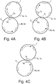
- Figures 4A to 4C are schematic illustrations of the impression cylinder 7 and plate cylinder 8 of Figures 1 and 2 , in different rotational positions, with their respective cylinder pits 7a, 8a, and cylinder segments 7b, 8b.
- an impression blanket and one or more underlying packing sheets are mounted on each cylinder segment 7b of the impression cylinder 7, while an intaglio printing plate (designated by reference 8c) is mounted on each cylinder segment 8b of the plate cylinder 8.
- Figure 4A illustrates the cylinders 7, 8 in a state where they are coming into rolling contact with one another, i.e. when a trailing end of the cylinder pits 7a, 8a leaves the printing nip.
- Figure 4B shows the cylinders 7, 8 in a state where they are in rolling contact with one another along their respective cylinder segments 7b, 8b.
- Figure 4C shows the cylinders 7, 8 in a state where the rolling contact between the cylinders is interrupted, i.e. when a leading end of the cylinder pits 7a, 8a enters the printing nip.
- Figure 5 is an enlarged view of the printing nip location (identified by reference A in Figure 4B ) schematically illustrating the local deformation of the impression blanket and packing sheets 7c (and of the sheet, not illustrated in Figure 5 ) as a result of the pressure applied at the printing nip when the plate cylinder 8 and impression cylinder 7 are in rolling contact with one another.
- the drawing of Figure 5 is not drawn to scale, but schematically illustrates that the impression blanket (and underlying packing sheets) 7c are compressed at the printing nip.
- the plate cylinder 8 and intaglio printing plate 8c are substantially rigid, whereas the impression blanket (and underlying packing sheets) 7c on the impression cylinder 7 are at least partly compressible.
- the effective radius of the plate cylinder 8 at the printing nip corresponds to the radius of the plate cylinder 8 (including the printing plate 8c), which radius is designated by reference R P in Figure 5 .
- the effective radius of the impression cylinder 7 at the printing nip designated by reference R I * in Figure 5
- R I * the effective radius of the impression cylinder 7 at the printing nip
- R I * the effective radius of the impression cylinder 7 at the printing nip
- FIG. 6 is a schematic illustration of a typical driving arrangement for cylinders 7, 8 comprising a main drive 100 which drives the plate cylinder 8 and the impression cylinder 7 into rotation via gears, the gears comprising a first gear 80 coupled to the plate cylinder 8 for rotation therewith and a second gear 70 meshing with the first gear 80 and being coupled to the impression cylinder 7 for rotation therewith.
- Gears 70, 80 are typically helical gears.
- the main drive 100 drives the first gear 80 into rotation (whether directly or indirectly), which first gear 80 acts as driving gear.
- the second gear 70 is driven by the first gear 80 at an average rotational speed that depends on the relevant gear ratio.
- the gears 70, 80 have the same size (and same number of teeth), meaning that the relevant gear ratio is 1:1.
- Figures 7A to 7C are three enlarged schematic views of location B indicated in Figure 6 , i.e. the location where the teeth 81 of the first gear 80 engage with the teeth 71 of the second gear 70.
- Figure 7A shows the first and second gears in a state where they are in driving contact with one another along a leading face 81a of the first gear 80.
- the gears 70, 80 typically engage, with a certain gear play (or "gear backlash") ⁇ being present between the teeth 71, 81 of the gears 70, 80.
- the second gear 70 is in effect driven into rotation by the first gear 80.
- Figure 7A illustrates the state of the first and second gears upon coming into rolling contact of the plate cylinder 8 and impression cylinder 7 one with the other as shown in Figure 4A , i.e. when a trailing end of the cylinder pits 7a, 8a leaves the printing nip.
- a high pressure is applied at the printing nip between the plate cylinder 8 and the impression cylinder 7, which leads to the deformation of the impression blanket (and underlying packing sheets) 7c as discussed in reference to Figure 5 and affects the rolling condition between the plate cylinder 8 and impression cylinder 7 as this will be explained hereinafter.
- the effective radius R I * of the impression cylinder 7 at the printing nip is smaller than the effective radius R P of the plate cylinder 8 and that the impression blanket and underlying packing sheets 7c behave essentially as a compressible medium
- the impression cylinder 7 will in effect be led to rotate, as a result of the friction with the plate cylinder 8, at a higher rotational speed compared to that of the plate cylinder 8.
- the second gear 70 will move away from the leading face 81a of the first gear 80 as shown in Figure 7B .
- the second gear 70 cannot however move indefinitely with respect to the first gear 80, but movement is restricted by the relevant gear backlash ⁇ .
- the second gear 70 may eventually come into contact with a trailing face 81b of the first gear 80 as shown in Figure 7C .
- the second gear 70 will in effect be blocked by the first gear 80 and the impression cylinder 7 forced to rotate at a rotational speed that is lower than that dictated by the friction between the two cylinders 7, 8. This will in effect lead to a slip (or slippage) between the circumferential surfaces of the plate cylinder 8 and impression cylinder 7, namely between the surface of the intaglio printing plate 8c and the surface of the impression blanket 7c, which is not desirable.
- the second gear 70 may be led to work against the rotation imposed by the first gear 80, which will likewise lead to a slip between the circumferential surfaces of the plate cylinder 8 and impression cylinder 7, which is not desirable either.
- Optimal rolling conditions can however be defined between the above two extreme situations, namely by ensuring that a rolling condition of the impression cylinder 7 with respect to the plate cylinder 8 substantially corresponds to a true rolling of the impression cylinder 7 with respect to the plate cylinder 8, i.e. a condition where no slippage occurs between a circumferential surface of the impression cylinder 7 and a circumferential surface of the plate cylinder 8.
- true rolling can in particular be achieved by ensuring that the second gear 70 is allowed to move with respect to the first gear 80, while the plate cylinder 8 and the impression cylinder 7 are in rolling contact with one another along their respective cylinder segments 8b, 7b, by an amount which does not exceed the gear backlash ⁇ of the first and second gears 80, 70.
- the desired rolling condition equating to true rolling corresponds to a condition where :
- the intaglio printing press is accordingly provided with a suitable monitoring system designed to monitor the rolling condition of the impression cylinder 7 with respect to the plate cylinder 8 and to provide an indication as to whether or not the rolling condition corresponds to a desired rolling condition.
- FIG 8 illustrates a preferred and non-limiting embodiment of a suitable monitoring system generally designated by reference numeral 150.
- This monitoring system 150 is advantageously designed to provide continuous or periodic measurements of a difference between a rotational position of the impression cylinder 7 and a rotational position of the plate cylinder 8 as the plate cylinder 8 and the impression cylinder 7 are in rolling contact with one another along their respective cylinder segments 8b, 7b.
- the monitoring system 150 preferably includes a first rotary encoder 800 measuring the rotational position of the plate cylinder 8 and a second rotary encoder 700 measuring the rotational position of the impression cylinder 7.
- Each rotary encoder 700, 800 provides a suitable measurement 705, resp. 805 of the rotational position of the associated cylinder 7, resp. 8.
- the rotary encoders 700, 800 can either be absolute rotary encoders providing an absolute measurement of the rotational position or incremental rotary encoders providing a relative measurement of the rotational position, namely an incremental change in rotational position.
- signals 705, 805 from the rotary encoders 700, 800 are supplied to a processing unit 200 which processes the signals 705, 805 and computes the difference between the rotational position of the impression cylinder 7 and the rotational position of the plate cylinder 8.
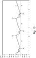
- the computed difference can be outputted directly by the processing unit 200 as a signal 205, for instance for display on monitor so that the operator of the press can visualize the rolling condition of the impression cylinder 7 with respect to the plate cylinder 8 (for instance in the form of a chart as shown in Figures 9 and 10 ).
- the processing unit 200 may further process the computed difference in order to identify whether or not the rolling condition corresponds to a desired rolling condition. Such further processing can be based on the following considerations discussed in reference to Figures 9 and 10 hereof.
- Figures 9 and 10 are schematic illustrations of exemplary curves "a" and "b" respectively representing an undesired and a desired rolling condition.
- the charts of Figures 9 and 10 actually show an example of a possible evolution over time (measured along the horizontal axis in Figures 9 , 10 ) of the difference between the rotational position of the impression cylinder 7 and the plate cylinder 8 (which difference is indicated along the vertical axis in Figures 9 , 10 ).
- the charts of Figures 9 and 10 show the relevant evolution of the difference in rotational position over a number of successive cylinder segments, points P1 being indicative of the moment coinciding with the coming into rolling contact of the plate cylinder 8 and impression cylinder 7 (as illustrated by Figure 4A ), while P2 is indicative of the moment coinciding with the end of the rolling contact between the plate cylinder 8 and impression cylinder 7 (as illustrated by Figure 4C ).
- the evolution of the curve between points P1 and P2 i.e. the segment of curve P1-P2 is representative of the relevant rolling condition for each relevant cylinder segment pair 7b-8b.
- the chart will therefore show the relevant rolling conditions for each of the three cylinder segment pairs 7b-8b in succession (references 1, 2, 3 in Figures 9 and 10 designating the relevant cylinder segment pairs 7b-8b).
- the segments of curve P1-P2 are in each case non-linear and in particular exhibit a point C beyond which the segment of curve apparently reaches a maximum. This point C coincides with the coming into contact of the second gear 70 with the trailing face 81b of the first gear 80 (as shown in Figure 7C ), which situation is undesirable. Beyond this point C, the rolling condition of the impression cylinder 7 with respect to the plate cylinder 8 does not correspond to a true rolling condition.
- a warning can be generated to draw the operator's attention.
- the operator may then take appropriate corrective actions, in particular adjust the pressure between the plate cylinder 8 and the impression cylinder 7, change an impression blanket and/or a packing sheet 7c on the impression cylinder 7, and/or change an intaglio printing plate 8c on the plate cylinder 8.
- the rolling condition may differ from one cylinder segment pair 7b-8b to another, in which case corrective actions may only need to be taken in relation the relevant cylinder segment pair 7b-8b for which an undesired rolling condition is detected.
- a geometry of a leading end of the cylinder pits 8a of the plate cylinder 8 (where the trailing end of the intaglio printing plate 8c is located and secured) is selected to match that of a leading end of the cylinder pits 7a of the impression cylinder 7 (where the trailing end of the impression blanket is located and secured).
- a geometry of a leading end of the cylinder pits 8a of the plate cylinder 8 (where the trailing end of the intaglio printing plate 8c is located and secured) is selected to match that of a leading end of the cylinder pits 7a of the impression cylinder 7 (where the trailing end of the impression blanket is located and secured).
- Different geometries at the leading end of the cylinder pits 7a, 8a may lead to the generation of undesired residual forces upon interruption of the rolling contact between the cylinder segments 7b, 8b.
- Figure 8 shows a monitoring system making use of rotary encoders to provide measurements of the rotational positions of the impression cylinder and plate cylinder
- speed sensors measuring the respective rotational speeds of the impression cylinder and plate cylinder and compute the difference of the rotational speeds rather than the difference of the rotational positions between the impression cylinder and plate cylinder.
- a constant speed difference would constitute an indication of the desired rolling condition.
- slippage between the circumferential surfaces of the plate cylinder and impression cylinder will be identified as a change in the difference of the rotational speeds of the impression cylinder and plate cylinder.
- the invention is applicable to any intaglio printing press comprising a plate cylinder carrying one or more intaglio printing plates and an impression cylinder cooperating with the plate cylinder as defined in the claims.
Landscapes
- Engineering & Computer Science (AREA)
- Mechanical Engineering (AREA)
- Rotary Presses (AREA)
- Inking, Control Or Cleaning Of Printing Machines (AREA)
- Printing Methods (AREA)
- Printing Plates And Materials Therefor (AREA)
Claims (15)
- Une presse d'impression taille-douce (1; 1*) comprenant un cylindre porte-plaque (8) portant une ou plusieurs plaques d'impression taille-douce (8c) et un cylindre d'impression (7) coopérant avec le cylindre porte-plaque (8), une zone d'impression étant formée entre le cylindre porte-plaque (8) et le cylindre d'impression (7),
le cylindre porte-plaque (8) et le cylindre d'impression (7) comprenant chacun une ou plusieurs fosses de cylindre (8a, 7a) et un nombre correspondant de segments de cylindre (8b, 7b), le cylindre porte-plaque (8) et le cylindre d'impression (7) étant en contact de roulement l'un avec l'autre pendant des opérations d'impression le long de leurs segments de cylindre (8b, 7b) respectifs lorsqu'aucune fosse de cylindre (8a, 7a) n'est présente au niveau de la zone d'impression,
caractérisée en ce que la presse d'impression taille-douce comprend un système de surveillance (150) conçu pour surveiller une condition de roulement du cylindre d'impression (7) par rapport au cylindre porte-plaque (8) et pour fournir une indication quant à savoir si la condition de roulement correspond ou non à une condition de roulement souhaitée, la condition de roulement souhaitée étant une condition de roulement correspondant à un roulement sans glissement du cylindre d'impression (7) par rapport au cylindre porte-plaque (8) où aucun glissement ne se produit entre une surface circonférentielle du cylindre d'impression (7) et une surface circonférentielle du cylindre porte-plaque (8). - La presse d'impression taille-douce (1; 1*) selon la revendication 1, dans laquelle le système de surveillance (150) est conçu pour fournir des mesures continues ou périodiques d'une différence entre une position de rotation du cylindre d'impression (7) et une position de rotation du cylindre porte-plaque (8) lorsque le cylindre porte-plaque (8) et le cylindre d'impression (7) sont en contact de roulement l'un avec l'autre le long de leurs segments de cylindre (8b, 7b) respectifs,
dans laquelle une évolution (P1-P2) de la différence entre la position de rotation du cylindre d'impression (7) et la position de rotation du cylindre porte-plaque (8) lorsque le cylindre porte-plaque (8) et le cylindre d'impression (7) sont en contact de roulement l'un avec l'autre le long de leurs segments de cylindre (8b, 7b) respectifs est indicative de la condition de roulement,
et dans laquelle le système de surveillance (150) est conçu pour fournir une indication de ladite évolution (P1-P2) qui est indicative de la condition de roulement. - La presse d'impression taille-douce (1; 1*) selon la revendication 2, dans laquelle le système de surveillance (150) inclut un premier encodeur rotatif (800) fournissant une mesure de la position de rotation du cylindre porte-plaque (8), un second encodeur rotatif (700) fournissant une mesure de la position de rotation du cylindre d'impression (7), et une unité de traitement (200) calculant la différence entre la position de rotation du cylindre d'impression (7) et la position de rotation du cylindre porte-plaque (8).
- La presse d'impression taille-douce (1; 1*) selon l'une quelconque des revendications précédentes, dans laquelle une géométrie d'une extrémité frontale des une ou plusieurs fosses de cylindre (8a) du cylindre porte-plaque (8) concorde avec celle d'une extrémité frontale des une ou plusieurs fosses de cylindre (7a) du cylindre d'impression (7).
- La presse d'impression taille-douce (1; 1*) selon l'une quelconque des revendications précédentes, comprenant en outre un entraînement principal (100) entraînant le cylindre porte-plaque (8) et le cylindre d'impression (7) en rotation via des engrenages comprenant un premier engrenage (80) couplé au cylindre porte-plaque (8) pour rotation avec le cylindre porte-plaque (8) et un second engrenage (70) engrenant avec le premier engrenage (80) et couplé au cylindre d'impression (7) pour rotation avec le cylindre d'impression (7),
dans laquelle la condition de roulement souhaitée correspond à une condition où le second engrenage (70) peut se déplacer par rapport au premier engrenage (80) alors que le cylindre porte-plaque (8) et le cylindre d'impression (7) sont en contact de roulement l'un avec l'autre le long de leurs segments de cylindre (8b, 7b) respectifs d'une quantité qui n'excède pas un jeu d'engrènement (Δ) des premier et second engrenages (80, 70). - La presse d'impression taille-douce (1; 1*) selon la revendication 5, dans laquelle le premier engrenage (80) est entraîné en rotation par l'entraînement principal (100) et agit comme un engrenage d'entraînement,
et dans laquelle la condition de roulement souhaitée correspond à une condition où :(i) le second engrenage (70) est en contact avec une face frontale (81a) du premier engrenage (80) lorsque le cylindre porte-plaque (8) et le cylindre d'impression (7) viennent en contact de roulement l'un avec l'autre, lorsqu'une extrémité arrière des fosses de cylindre (8a, 7a) quitte la zone d'impression ;(ii) i) le second engrenage (70) peut s'éloigner de la face frontale (81a) du premier engrenage (80) alors que le cylindre porte-plaque (8) et le cylindre d'impression (7) sont en contact de roulement l'un avec l'autre le long de leurs segments de cylindre (8b, 7b) respectifs ; et(iii) le second engrenage (70) ne vient pas en contact avec une face arrière (81b) du premier engrenage (80) avant que le contact de roulement entre le cylindre porte-plaque (8) et le cylindre d'impression (7) soit interrompu, lorsqu'une extrémité frontale des fosses de cylindre (8a, 7a) entre dans la zone d'impression. - La presse d'impression taille-douce (1; 1*) selon l'une quelconque des revendications précédentes, dans laquelle le système de surveillance (150) surveille la condition de roulement du cylindre d'impression (7) par rapport au cylindre porte-plaque (8) pour chaque segment de cylindre (7b) du cylindre d'impression (7) venant en contact de roulement avec l'un concerné des segments de cylindre (8b) du cylindre porte-plaque (8).
- La presse d'impression taille-douce (1; 1*) selon l'une quelconque des revendications précédentes, dans laquelle le système de surveillance (150) est en outre conçu pour délivrer un avertissement au cas où la condition de roulement est indicative d'une condition de roulement non souhaitée.
- La presse d'impression taille-douce (1; 1*) selon l'une quelconque des revendications précédentes, dans laquelle le cylindre porte-plaque (8) et le cylindre d'impression (7) présentent le même nombre de fosses de cylindre (8a, 7a) et de segments de cylindre (8b, 7b).
- Un procédé de surveillance du fonctionnement d'une presse d'impression taille-douce (1; 1*) comprenant un cylindre porte-plaque (8) portant une ou plusieurs plaques d'impression taille-douce (8c) et un cylindre d'impression (7) coopérant avec le cylindre porte-plaque (8), une zone d'impression étant formée entre le cylindre porte-plaque (8) et le cylindre d'impression (7),
le cylindre porte-plaque (8) et le cylindre d'impression (7) comprenant chacun une ou plusieurs fosses de cylindre (8a, 7a) et un nombre correspondant de segments de cylindre (8b, 7b), le cylindre porte-plaque (8) et le cylindre d'impression (7) étant en contact de roulement l'un avec l'autre pendant des opérations d'impression le long de leurs segments de cylindre (8b, 7b) respectifs lorsqu'aucune fosse de cylindre (8a, 7a) n'est présente au niveau de la zone d'impression,
caractérisé en ce que le procédé comprend les étapes de surveillance d'une condition de roulement du cylindre d'impression (7) par rapport au cylindre porte-plaque (8) et de fourniture d'une indication quant à savoir si la condition de roulement correspond ou non à une condition de roulement souhaitée, la condition de roulement souhaitée étant une condition de roulement correspondant à un roulement sans glissement du cylindre d'impression (7) par rapport au cylindre porte-plaque (8) où aucun glissement ne se produit entre une surface circonférentielle du cylindre d'impression (7) et une surface circonférentielle du cylindre porte-plaque (8). - Le procédé selon la revendication 10, dans lequel l'étape de surveillance inclut la fourniture de mesures continues ou périodiques d'une différence entre une position de rotation du cylindre d'impression (7) et une position de rotation du cylindre porte-plaque (8) lorsque le cylindre porte-plaque (8) et le cylindre d'impression (7) sont en contact de roulement l'un avec l'autre le long de leurs segments de cylindre (8b, 7b) respectifs,
et dans lequel une évolution (P1-P2) de la différence entre la position de rotation du cylindre d'impression (7) et la position de rotation du cylindre porte-plaque (8) lorsque le cylindre porte-plaque (8) et le cylindre d'impression (7) sont en contact de roulement l'un avec l'autre le long de leurs segments de cylindre (8b, 7b) respectifs est indicative de la condition de roulement, - Le procédé selon la revendication 11, dans lequel une évolution sensiblement linéaire (P1-P2, Figure 10) de la différence entre la position de rotation du cylindre d'impression (7) et la position de rotation du cylindre porte-plaque (8) lorsque le cylindre porte-plaque (8) et le cylindre d'impression (7) sont en contact de roulement l'un avec l'autre le long de leurs segments de cylindre (8b, 7b) respectifs est indicative de la condition de roulement souhaitée,
et dans lequel une évolution sensiblement non linéaire (P1-P2, Figure 9) de la différence entre la position de rotation du cylindre d'impression (7) et la position de rotation du cylindre porte-plaque (8) lorsque le cylindre porte-plaque (8) et le cylindre d'impression (7) sont en contact de roulement l'un avec l'autre le long de leurs segments de cylindre (8b, 7b) respectifs est indicative d'une condition de roulement non souhaitée. - Le procédé selon l'une quelconque des revendications 10 à 12, dans lequel la presse d'impression taille-douce (1; 1*) comprend en outre un entraînement principal (100) entraînant le cylindre porte-plaque (8) et le cylindre d d'impression (7) en rotation via des engrenages, lesquels engrenages comprennent un premier engrenage (80) couplé au cylindre porte-plaque (8) pour rotation avec le cylindre porte-plaque (8) et un second engrenage (70) engrenant avec le premier engrenage (80) et étant couplé au cylindre d'impression (7) pour rotation avec le cylindre d'impression (7),
dans lequel la condition de roulement souhaitée correspond à une condition où le second engrenage (70) peut se déplacer par rapport au premier engrenage (80) pendant que le cylindre porte-plaque (8) et le cylindre d'impression (7) sont en contact de roulement l'un avec l'autre le long de leurs segments de cylindre (8b, 7b) respectifs d'une quantité qui n'excède pas un jeu d'engrènement (Δ) des premier et second engrenages (80, 70). - Le procédé selon la revendication 13, dans lequel le premier engrenage (80) est entraîné en rotation par l'entraînement principal (100) et agit comme un engrenage d'entraînement,
et dans lequel la condition de roulement souhaitée correspond à une condition où :(i) le second engrenage (70) est en contact avec une face frontale (81a) du premier engrenage (80) lorsque le cylindre porte-plaque (8) et le cylindre d'impression (7) viennent en contact de roulement l'un avec l'autre, lorsqu'une extrémité arrière des fosses de cylindre (8a, 7a) quitte la zone d'impression ;(ii) le second engrenage (70) peut s'éloigner de la face frontale (81a) du premier engrenage (80) alors que le cylindre porte-plaque (8) et le cylindre d'impression (7) sont en contact de roulement l'un avec l'autre ; et(iii) le second engrenage (70) ne vient pas en contact avec une face arrière (81b) du premier engrenage (80) avant que le contact de roulement entre le cylindre porte-plaque (8) et le cylindre d'impression (7) soit interrompu, lorsqu'une extrémité frontale des fosses de cylindre (8a, 7a) entre dans la zone d'impression. - Le procédé selon l'une quelconque des revendications 10 à 14, comprenant en outre l'étape de génération d'un avertissement dans le cas où la condition de roulement est indicative d'une condition de roulement non souhaitée.
Priority Applications (2)
| Application Number | Priority Date | Filing Date | Title |
|---|---|---|---|
| EP13792492.4A EP2909033B1 (fr) | 2012-10-18 | 2013-10-18 | Presse d'impression en héliogravure et procédé de surveillance de fonctionnement de celle-ci |
| PL13792492T PL2909033T3 (pl) | 2012-10-18 | 2013-10-18 | Prasa wklęsłodrukowa i sposób monitorowania jej pracy |
Applications Claiming Priority (3)
| Application Number | Priority Date | Filing Date | Title |
|---|---|---|---|
| EP12189131.1A EP2722179A1 (fr) | 2012-10-18 | 2012-10-18 | Presse d'impression en héliogravure et procédé de surveillance de fonctionnement de celle-ci |
| EP13792492.4A EP2909033B1 (fr) | 2012-10-18 | 2013-10-18 | Presse d'impression en héliogravure et procédé de surveillance de fonctionnement de celle-ci |
| PCT/IB2013/059448 WO2014060997A1 (fr) | 2012-10-18 | 2013-10-18 | Presse d'impression en creux et procédé de surveillance de son fonctionnement |
Publications (2)
| Publication Number | Publication Date |
|---|---|
| EP2909033A1 EP2909033A1 (fr) | 2015-08-26 |
| EP2909033B1 true EP2909033B1 (fr) | 2017-09-27 |
Family
ID=47018916
Family Applications (2)
| Application Number | Title | Priority Date | Filing Date |
|---|---|---|---|
| EP12189131.1A Withdrawn EP2722179A1 (fr) | 2012-10-18 | 2012-10-18 | Presse d'impression en héliogravure et procédé de surveillance de fonctionnement de celle-ci |
| EP13792492.4A Not-in-force EP2909033B1 (fr) | 2012-10-18 | 2013-10-18 | Presse d'impression en héliogravure et procédé de surveillance de fonctionnement de celle-ci |
Family Applications Before (1)
| Application Number | Title | Priority Date | Filing Date |
|---|---|---|---|
| EP12189131.1A Withdrawn EP2722179A1 (fr) | 2012-10-18 | 2012-10-18 | Presse d'impression en héliogravure et procédé de surveillance de fonctionnement de celle-ci |
Country Status (16)
| Country | Link |
|---|---|
| US (1) | US9211696B2 (fr) |
| EP (2) | EP2722179A1 (fr) |
| JP (1) | JP6281956B2 (fr) |
| KR (1) | KR101972058B1 (fr) |
| CN (1) | CN104755268B (fr) |
| AU (1) | AU2013333456B2 (fr) |
| BR (1) | BR112015008342A2 (fr) |
| CA (1) | CA2887166C (fr) |
| ES (1) | ES2645084T3 (fr) |
| IN (1) | IN2015DN02745A (fr) |
| MX (1) | MX353077B (fr) |
| PH (1) | PH12015500811A1 (fr) |
| PL (1) | PL2909033T3 (fr) |
| RU (1) | RU2640274C2 (fr) |
| WO (1) | WO2014060997A1 (fr) |
| ZA (1) | ZA201503360B (fr) |
Cited By (16)
| Publication number | Priority date | Publication date | Assignee | Title |
|---|---|---|---|---|
| DE102019103788A1 (de) | 2019-02-05 | 2020-08-06 | Koenig & Bauer Ag | Druckwerk und Druckmaschine mit einem Druckwerk |
| DE102019102856A1 (de) | 2019-02-05 | 2020-08-06 | Koenig & Bauer Ag | Druckwerk und Druckmaschine mit mindestens einem Druckwerk sowie Verfahren zum Bedrucken |
| WO2020161056A1 (fr) | 2019-02-05 | 2020-08-13 | Koenig & Bauer Ag | Système d'impression en creux d'une machine à imprimer comportant un dispositif d'encrage et procédé d'impression en creux |
| WO2020161058A2 (fr) | 2019-02-05 | 2020-08-13 | Koenig & Bauer Ag | Unités d'impression en creux pour l'impression sur substrat, procédé pour définir et/ou changer un transfert d'encre et pour faire fonctionner une unité d'impression en creux |
| WO2020161057A1 (fr) | 2019-02-05 | 2020-08-13 | Koenig & Bauer Ag | Système d'impression en creux d'une machine à imprimer et plaque de transfert d'encre d'un cylindre de dispositif d'encrage |
| DE102019111803A1 (de) * | 2019-05-07 | 2020-11-12 | Koenig & Bauer Ag | Verfahren zum Betreiben eines Druckwerks sowie Druckmaschine mit einem Druckwerk |
| DE102019111804A1 (de) * | 2019-05-07 | 2020-11-12 | Koenig & Bauer Ag | Verfahren zum Einstellen und/oder Ändern eines Farbtransfers, Druckwerk sowie Druckmaschine mit einem Druckwerk |
| DE102019111802A1 (de) * | 2019-05-07 | 2020-11-12 | Koenig & Bauer Ag | Verfahren zum Betreiben eines Druckwerks, Substratabschnitt sowie Druckwerk |
| DE102019111806A1 (de) * | 2019-05-07 | 2020-11-12 | Koenig & Bauer Ag | Verfahren zum Einstellen und/oder Ändern eines Farbtransfers, Druckwerk sowie Druckmaschine mit einem Druckwerk |
| WO2020224815A1 (fr) | 2019-05-07 | 2020-11-12 | Koenig & Bauer Ag | Système d'impression en creux, section de substrat, procédé pour la commande d'une position relative et procédé de fonctionnement d'un système d'impression en creux |
| DE102019118435A1 (de) * | 2019-07-08 | 2021-01-14 | Koenig & Bauer Ag | Druckwerk, Druckmaschine mit einem Druckwerk und Verfahren zum Bedrucken von Substrat |
| DE102020102622A1 (de) | 2020-02-03 | 2021-08-05 | Koenig & Bauer Ag | Tiefdruckwerk |
| DE102024112333A1 (de) * | 2024-05-02 | 2025-11-06 | Koenig & Bauer Ag | Druckwerk zum Bedrucken von Substrat nach einem Tiefdruckverfahren |
| DE102024112328A1 (de) * | 2024-05-02 | 2025-11-06 | Koenig & Bauer Ag | Druckwerk zum Bedrucken von Substrat nach einem Tiefdruckverfahren |
| DE102024112330A1 (de) * | 2024-05-02 | 2025-11-06 | Koenig & Bauer Ag | Druckwerk zum Bedrucken von Substrat nach einem Tiefdruckverfahren sowie ein Verfahren zum Betreiben eines nach einem Tiefdruckverfahren arbeitenden Druckwerks |
| DE102024112331A1 (de) * | 2024-05-02 | 2025-11-06 | Koenig & Bauer Ag | Druckwerk zum Bedrucken von Substrat nach einem Tiefdruckverfahren |
Families Citing this family (5)
| Publication number | Priority date | Publication date | Assignee | Title |
|---|---|---|---|---|
| JP5943867B2 (ja) * | 2013-03-26 | 2016-07-05 | 富士フイルム株式会社 | 印刷装置及び印刷方法 |
| JP6666780B2 (ja) * | 2016-04-11 | 2020-03-18 | 株式会社小森コーポレーション | 電子デバイス製造装置 |
| JP6978957B2 (ja) * | 2018-02-13 | 2021-12-08 | 三菱重工業株式会社 | 組立体の製造方法、補強部材、及び組立体 |
| CN109109452B (zh) * | 2018-07-24 | 2020-12-04 | 重庆安卡自动化工程有限公司 | 用于瓦楞纸箱印刷机械的网纹辊控制系统 |
| CN109130457B (zh) * | 2018-11-01 | 2023-11-14 | 大连巨通塑料制品有限公司 | 凹版印刷机版辊密封装置 |
Family Cites Families (33)
| Publication number | Priority date | Publication date | Assignee | Title |
|---|---|---|---|---|
| CH477293A (de) | 1967-12-19 | 1969-08-31 | Giori Gualtiero | Mehrfarben-Stahlstichdruckmaschine zur Herstellung von Wertscheinen, insbesondere Banknoten |
| DD141649A1 (de) * | 1979-03-26 | 1980-05-14 | Tappert Hans Juergen | Einrichtung zur druckpressungsregelung an druckmaschinen |
| AU550695B2 (en) | 1982-04-07 | 1986-03-27 | De La Rue Giori S.A. | Copperplate engraving machine for paper currency |
| DE3867455D1 (de) * | 1988-01-07 | 1992-02-13 | Komori Printing Mach | Vorrichtung zum detektieren von fehlerhaften exemplaren. |
| DE69008941T2 (de) | 1989-06-29 | 1994-12-15 | De La Rue Giori Sa | Tiefdruckmaschine zum Drucken von Wertpapieren. |
| US5062360A (en) | 1989-08-30 | 1991-11-05 | De La Rue Giori S.A. | Combined rotary web-fed printing machine, especially for the printing of securities |
| JP2589863B2 (ja) * | 1990-04-25 | 1997-03-12 | ハマダ印刷機械株式会社 | 印刷機 |
| EP0563007B1 (fr) | 1992-03-26 | 1996-07-10 | De La Rue Giori S.A. | Machine à imprimer en creux |
| DE59406405D1 (de) * | 1993-09-17 | 1998-08-13 | De La Rue Giori Sa | Druckwerk für eine Rollendruckmaschine |
| DE4401362C2 (de) * | 1994-01-18 | 1997-12-11 | Roland Man Druckmasch | Verfahren und Rotationsdruckmaschine für indirekten Tiefdruck |
| JP3718275B2 (ja) | 1996-01-12 | 2005-11-24 | 株式会社小森コーポレーション | 印刷機 |
| DE19613084A1 (de) | 1996-04-02 | 1997-10-09 | Koenig & Bauer Albert Ag | Saugkasten zum Führen von Bogen |
| DE19613082C2 (de) | 1996-04-02 | 1999-10-21 | Koenig & Bauer Ag | Verfahren und Vorrichtung zur qualitativen Beurteilung von bearbeitetem Material |
| CA2232695C (fr) | 1997-04-14 | 2005-02-01 | De La Rue Giori S.A. | Presse a imprimer a l'heliogravure |
| WO2001054904A1 (fr) | 2000-01-25 | 2001-08-02 | Koenig & Bauer Aktiengesellschaft | Presse pour impression en creux |
| WO2001081087A1 (fr) * | 2000-04-25 | 2001-11-01 | Mitsubishi Heavy Industries, Ltd. | Procede et appareil permettant de detecter un dephasage angulaire |
| US6684776B2 (en) * | 2001-02-23 | 2004-02-03 | Heidelberger Druckmaschinen Ag | Method and apparatus for determining slipping in a nip roller |
| CN1325251C (zh) * | 2001-08-03 | 2007-07-11 | 柯尼格及包尔公开股份有限公司 | 印刷机的印刷装置 |
| DE10158093B4 (de) | 2001-11-27 | 2004-07-08 | Koenig & Bauer Ag | Tiefdruckmaschine |
| DE10207073B4 (de) | 2002-02-20 | 2005-11-24 | Koenig & Bauer Ag | Vorrichtung zum Transport von Bogen mit einem Bogenleitelement |
| EP1400353A1 (fr) * | 2002-09-19 | 2004-03-24 | Kba-Giori S.A. | Machine d'impression en creux |
| EP1442878A1 (fr) * | 2003-02-03 | 2004-08-04 | Kba-Giori S.A. | Entraínement du dispositif d'encrage dans une machine d'impression en creux |
| JP4362653B2 (ja) * | 2004-04-30 | 2009-11-11 | 独立行政法人 国立印刷局 | 凹版印刷機の押圧力検出方法及びその検出システム |
| EP1602483A1 (fr) | 2004-06-03 | 2005-12-07 | Kba-Giori S.A. | Machine d'impression intaglio et procédé correspondant |
| EP1602482A1 (fr) | 2004-06-03 | 2005-12-07 | Kba-Giori S.A. | Machine intaglio avec des cylindres en phase |
| KR100634327B1 (ko) * | 2005-04-13 | 2006-10-13 | 한국기계연구원 | 롤-투-롤 윤전인쇄방식을 이용한 전자소자의 제조방법 및그 제조장치 |
| JP2007038481A (ja) * | 2005-08-02 | 2007-02-15 | Mitsubishi Heavy Ind Ltd | 印刷機およびその制御方法 |
| EP1844930A1 (fr) | 2006-04-11 | 2007-10-17 | Kba-Giori S.A. | Dispositif d'essuyage de l'encre pour une machine d'impression |
| CN100400285C (zh) * | 2006-08-02 | 2008-07-09 | 广西真龙彩印包装有限公司 | 一种单张纸凹版印刷机 |
| JP2009000883A (ja) * | 2007-06-21 | 2009-01-08 | Komori Corp | 印刷機の印刷品質管理方法及び装置 |
| EP2338682A1 (fr) | 2009-12-22 | 2011-06-29 | KBA-NotaSys SA | Presse d'impression intaglio dotée d'un chariot mobile supportant un cylindre Orlof |
| JP2011136464A (ja) * | 2009-12-28 | 2011-07-14 | National Printing Bureau | 印刷機の駆動制御方法及び駆動制御装置 |
| EP2399745A1 (fr) | 2010-06-25 | 2011-12-28 | KBA-NotaSys SA | Système d'inspection pour l'inspection en ligne de documents imprimés produits sur une presse d'impression de rotogravure |
-
2012
- 2012-10-18 EP EP12189131.1A patent/EP2722179A1/fr not_active Withdrawn
-
2013
- 2013-10-18 ES ES13792492.4T patent/ES2645084T3/es active Active
- 2013-10-18 CN CN201380054840.XA patent/CN104755268B/zh not_active Expired - Fee Related
- 2013-10-18 EP EP13792492.4A patent/EP2909033B1/fr not_active Not-in-force
- 2013-10-18 IN IN2745DEN2015 patent/IN2015DN02745A/en unknown
- 2013-10-18 BR BR112015008342A patent/BR112015008342A2/pt not_active Application Discontinuation
- 2013-10-18 RU RU2015115959A patent/RU2640274C2/ru not_active IP Right Cessation
- 2013-10-18 KR KR1020157012003A patent/KR101972058B1/ko not_active Expired - Fee Related
- 2013-10-18 JP JP2015537408A patent/JP6281956B2/ja not_active Expired - Fee Related
- 2013-10-18 PL PL13792492T patent/PL2909033T3/pl unknown
- 2013-10-18 MX MX2015004939A patent/MX353077B/es active IP Right Grant
- 2013-10-18 AU AU2013333456A patent/AU2013333456B2/en not_active Ceased
- 2013-10-18 US US14/433,299 patent/US9211696B2/en not_active Expired - Fee Related
- 2013-10-18 CA CA2887166A patent/CA2887166C/fr not_active Expired - Fee Related
- 2013-10-18 WO PCT/IB2013/059448 patent/WO2014060997A1/fr not_active Ceased
-
2015
- 2015-04-13 PH PH12015500811A patent/PH12015500811A1/en unknown
- 2015-05-14 ZA ZA2015/03360A patent/ZA201503360B/en unknown
Non-Patent Citations (1)
| Title |
|---|
| None * |
Cited By (34)
| Publication number | Priority date | Publication date | Assignee | Title |
|---|---|---|---|---|
| WO2020161057A1 (fr) | 2019-02-05 | 2020-08-13 | Koenig & Bauer Ag | Système d'impression en creux d'une machine à imprimer et plaque de transfert d'encre d'un cylindre de dispositif d'encrage |
| DE102019105066A1 (de) | 2019-02-05 | 2020-08-06 | Koenig & Bauer Ag | Druckwerk, Druckmaschine mit einem Druckwerk sowie Verfahren zum Rüsten |
| DE102019103787A1 (de) | 2019-02-05 | 2020-08-06 | Koenig & Bauer Ag | Druckwerk und Druckmaschine mit einem Druckwerk |
| DE102019103784A1 (de) | 2019-02-05 | 2020-08-06 | Koenig & Bauer Ag | Druckwerk und Druckmaschine mit einem Druckwerk sowie Verfahren zum Bedrucken |
| DE102019103789A1 (de) | 2019-02-05 | 2020-08-06 | Koenig & Bauer Ag | Druckwerk und Druckmaschine mit einem Druckwerk |
| DE102019105067A1 (de) | 2019-02-05 | 2020-08-06 | Koenig & Bauer Ag | Druckwerk und Druckmaschine mit einem Druckwerk und Verfahren zum Stellen eines Farbwerkszylinders |
| DE102019103785A1 (de) | 2019-02-05 | 2020-08-06 | Koenig & Bauer Ag | Druckwerk und Druckmaschine mit einem Druckwerk |
| DE102019107734A1 (de) | 2019-02-05 | 2020-08-06 | Koenig & Bauer Ag | Druckwerk, Druckmaschine mit einem Druckwerk sowie Verfahren zum Betreiben eines nach dem Tiefdruckverfahren arbeitenden Druckwerks |
| DE102019102856A1 (de) | 2019-02-05 | 2020-08-06 | Koenig & Bauer Ag | Druckwerk und Druckmaschine mit mindestens einem Druckwerk sowie Verfahren zum Bedrucken |
| US11440312B2 (en) | 2019-02-05 | 2022-09-13 | Koenig & Bauer Ag | Gravure printing units for printing onto substrates by a gravure printing method |
| US11504962B2 (en) | 2019-02-05 | 2022-11-22 | Koenig & Bauer Ag | Gravure printing units for printing onto substrate, printing press with such a gravure printing unit, ink transfer forme and method for setting up an inking unit cylinder comprised by a gravure printing unit |
| DE102019103790A1 (de) | 2019-02-05 | 2020-08-06 | Koenig & Bauer Ag | Druckwerk und Druckmaschine mit einem Druckwerk |
| DE102019107735A1 (de) | 2019-02-05 | 2020-08-06 | Koenig & Bauer Ag | Druckwerk, Druckmaschine mit einem Druckwerk sowie Verfahren zum Rüsten |
| DE102019104593A1 (de) | 2019-02-05 | 2020-08-06 | Koenig & Bauer Ag | Farbübertragungsform sowie Verfahren zu dessen Herstellung |
| WO2020161056A1 (fr) | 2019-02-05 | 2020-08-13 | Koenig & Bauer Ag | Système d'impression en creux d'une machine à imprimer comportant un dispositif d'encrage et procédé d'impression en creux |
| WO2020161058A2 (fr) | 2019-02-05 | 2020-08-13 | Koenig & Bauer Ag | Unités d'impression en creux pour l'impression sur substrat, procédé pour définir et/ou changer un transfert d'encre et pour faire fonctionner une unité d'impression en creux |
| DE102019104591A1 (de) | 2019-02-05 | 2020-08-06 | Koenig & Bauer Ag | Druckwerk und Druckmaschine mit einem Druckwerk und Verfahren zum Rüsten |
| DE102019103788A1 (de) | 2019-02-05 | 2020-08-06 | Koenig & Bauer Ag | Druckwerk und Druckmaschine mit einem Druckwerk |
| DE102019104592A1 (de) | 2019-02-05 | 2020-08-06 | Koenig & Bauer Ag | Druckwerk und Druckmaschine mit einem Druckwerk |
| DE102019111803A1 (de) * | 2019-05-07 | 2020-11-12 | Koenig & Bauer Ag | Verfahren zum Betreiben eines Druckwerks sowie Druckmaschine mit einem Druckwerk |
| DE102019111802A1 (de) * | 2019-05-07 | 2020-11-12 | Koenig & Bauer Ag | Verfahren zum Betreiben eines Druckwerks, Substratabschnitt sowie Druckwerk |
| WO2020224815A1 (fr) | 2019-05-07 | 2020-11-12 | Koenig & Bauer Ag | Système d'impression en creux, section de substrat, procédé pour la commande d'une position relative et procédé de fonctionnement d'un système d'impression en creux |
| DE102019111806A1 (de) * | 2019-05-07 | 2020-11-12 | Koenig & Bauer Ag | Verfahren zum Einstellen und/oder Ändern eines Farbtransfers, Druckwerk sowie Druckmaschine mit einem Druckwerk |
| DE102019111804A1 (de) * | 2019-05-07 | 2020-11-12 | Koenig & Bauer Ag | Verfahren zum Einstellen und/oder Ändern eines Farbtransfers, Druckwerk sowie Druckmaschine mit einem Druckwerk |
| US11396195B2 (en) | 2019-05-07 | 2022-07-26 | Koenig & Bauer Ag | Gravure printing unit and method for checking and/or adjusting and/or correcting a relative position |
| DE102019118435A1 (de) * | 2019-07-08 | 2021-01-14 | Koenig & Bauer Ag | Druckwerk, Druckmaschine mit einem Druckwerk und Verfahren zum Bedrucken von Substrat |
| DE102020102622A1 (de) | 2020-02-03 | 2021-08-05 | Koenig & Bauer Ag | Tiefdruckwerk |
| WO2021155967A1 (fr) | 2020-02-03 | 2021-08-12 | Koenig & Bauer Ag | Unité d'héliogravure dotée de cylindres d'unité d'encrage |
| US11724485B2 (en) | 2020-02-03 | 2023-08-15 | Koenig & Bauer Ag | Gravure printing unit with inking unit cylinders |
| DE102024112333A1 (de) * | 2024-05-02 | 2025-11-06 | Koenig & Bauer Ag | Druckwerk zum Bedrucken von Substrat nach einem Tiefdruckverfahren |
| DE102024112328A1 (de) * | 2024-05-02 | 2025-11-06 | Koenig & Bauer Ag | Druckwerk zum Bedrucken von Substrat nach einem Tiefdruckverfahren |
| DE102024112330A1 (de) * | 2024-05-02 | 2025-11-06 | Koenig & Bauer Ag | Druckwerk zum Bedrucken von Substrat nach einem Tiefdruckverfahren sowie ein Verfahren zum Betreiben eines nach einem Tiefdruckverfahren arbeitenden Druckwerks |
| DE102024112331A1 (de) * | 2024-05-02 | 2025-11-06 | Koenig & Bauer Ag | Druckwerk zum Bedrucken von Substrat nach einem Tiefdruckverfahren |
| WO2025228585A1 (fr) | 2024-05-02 | 2025-11-06 | Koenig & Bauer Ag | Unités d'impression pour impression sur un substrat selon un procédé d'impression en creux et procédé de fonctionnement d'une unité d'impression fonctionnant selon un procédé d'impression en creux |
Also Published As
| Publication number | Publication date |
|---|---|
| CA2887166C (fr) | 2018-11-13 |
| BR112015008342A2 (pt) | 2017-07-04 |
| ES2645084T3 (es) | 2017-12-04 |
| RU2015115959A (ru) | 2016-12-10 |
| PH12015500811B1 (en) | 2015-06-08 |
| IN2015DN02745A (fr) | 2015-08-28 |
| EP2722179A1 (fr) | 2014-04-23 |
| MX353077B (es) | 2017-12-19 |
| CN104755268A (zh) | 2015-07-01 |
| US20150258777A1 (en) | 2015-09-17 |
| MX2015004939A (es) | 2015-07-21 |
| ZA201503360B (en) | 2016-11-30 |
| KR20150070229A (ko) | 2015-06-24 |
| WO2014060997A1 (fr) | 2014-04-24 |
| JP2016500588A (ja) | 2016-01-14 |
| EP2909033A1 (fr) | 2015-08-26 |
| JP6281956B2 (ja) | 2018-02-21 |
| US9211696B2 (en) | 2015-12-15 |
| PL2909033T3 (pl) | 2018-01-31 |
| AU2013333456A1 (en) | 2015-04-23 |
| PH12015500811A1 (en) | 2015-06-08 |
| KR101972058B1 (ko) | 2019-08-16 |
| CA2887166A1 (fr) | 2014-04-24 |
| RU2640274C2 (ru) | 2017-12-27 |
| AU2013333456B2 (en) | 2016-11-03 |
| CN104755268B (zh) | 2017-07-07 |
Similar Documents
| Publication | Publication Date | Title |
|---|---|---|
| CA2887166C (fr) | Presse d'impression en creux et procede de surveillance de son fonctionnement | |
| US9738065B2 (en) | Intaglio printing press | |
| EP2399745A1 (fr) | Système d'inspection pour l'inspection en ligne de documents imprimés produits sur une presse d'impression de rotogravure | |
| CN1747833A (zh) | 凹版印刷机中着墨单元的驱动装置 | |
| EP2849947B1 (fr) | Presse à imprimer avec chariot d'encrage mobile |
Legal Events
| Date | Code | Title | Description |
|---|---|---|---|
| PUAI | Public reference made under article 153(3) epc to a published international application that has entered the european phase |
Free format text: ORIGINAL CODE: 0009012 |
|
| 17P | Request for examination filed |
Effective date: 20150401 |
|
| AK | Designated contracting states |
Kind code of ref document: A1 Designated state(s): AL AT BE BG CH CY CZ DE DK EE ES FI FR GB GR HR HU IE IS IT LI LT LU LV MC MK MT NL NO PL PT RO RS SE SI SK SM TR |
|
| AX | Request for extension of the european patent |
Extension state: BA ME |
|
| DAX | Request for extension of the european patent (deleted) | ||
| GRAP | Despatch of communication of intention to grant a patent |
Free format text: ORIGINAL CODE: EPIDOSNIGR1 |
|
| INTG | Intention to grant announced |
Effective date: 20170413 |
|
| GRAS | Grant fee paid |
Free format text: ORIGINAL CODE: EPIDOSNIGR3 |
|
| GRAA | (expected) grant |
Free format text: ORIGINAL CODE: 0009210 |
|
| REG | Reference to a national code |
Ref country code: FR Ref legal event code: PLFP Year of fee payment: 5 |
|
| AK | Designated contracting states |
Kind code of ref document: B1 Designated state(s): AL AT BE BG CH CY CZ DE DK EE ES FI FR GB GR HR HU IE IS IT LI LT LU LV MC MK MT NL NO PL PT RO RS SE SI SK SM TR |
|
| REG | Reference to a national code |
Ref country code: GB Ref legal event code: FG4D |
|
| REG | Reference to a national code |
Ref country code: CH Ref legal event code: EP |
|
| REG | Reference to a national code |
Ref country code: AT Ref legal event code: REF Ref document number: 931599 Country of ref document: AT Kind code of ref document: T Effective date: 20171015 |
|
| REG | Reference to a national code |
Ref country code: IE Ref legal event code: FG4D |
|
| REG | Reference to a national code |
Ref country code: RO Ref legal event code: EPE |
|
| REG | Reference to a national code |
Ref country code: SE Ref legal event code: TRGR |
|
| REG | Reference to a national code |
Ref country code: NL Ref legal event code: FP |
|
| REG | Reference to a national code |
Ref country code: DE Ref legal event code: R096 Ref document number: 602013027221 Country of ref document: DE |
|
| REG | Reference to a national code |
Ref country code: ES Ref legal event code: FG2A Ref document number: 2645084 Country of ref document: ES Kind code of ref document: T3 Effective date: 20171204 |
|
| PG25 | Lapsed in a contracting state [announced via postgrant information from national office to epo] |
Ref country code: FI Free format text: LAPSE BECAUSE OF FAILURE TO SUBMIT A TRANSLATION OF THE DESCRIPTION OR TO PAY THE FEE WITHIN THE PRESCRIBED TIME-LIMIT Effective date: 20170927 Ref country code: NO Free format text: LAPSE BECAUSE OF FAILURE TO SUBMIT A TRANSLATION OF THE DESCRIPTION OR TO PAY THE FEE WITHIN THE PRESCRIBED TIME-LIMIT Effective date: 20171227 Ref country code: HR Free format text: LAPSE BECAUSE OF FAILURE TO SUBMIT A TRANSLATION OF THE DESCRIPTION OR TO PAY THE FEE WITHIN THE PRESCRIBED TIME-LIMIT Effective date: 20170927 Ref country code: LT Free format text: LAPSE BECAUSE OF FAILURE TO SUBMIT A TRANSLATION OF THE DESCRIPTION OR TO PAY THE FEE WITHIN THE PRESCRIBED TIME-LIMIT Effective date: 20170927 |
|
| REG | Reference to a national code |
Ref country code: LT Ref legal event code: MG4D |
|
| PG25 | Lapsed in a contracting state [announced via postgrant information from national office to epo] |
Ref country code: RS Free format text: LAPSE BECAUSE OF FAILURE TO SUBMIT A TRANSLATION OF THE DESCRIPTION OR TO PAY THE FEE WITHIN THE PRESCRIBED TIME-LIMIT Effective date: 20170927 Ref country code: LV Free format text: LAPSE BECAUSE OF FAILURE TO SUBMIT A TRANSLATION OF THE DESCRIPTION OR TO PAY THE FEE WITHIN THE PRESCRIBED TIME-LIMIT Effective date: 20170927 |
|
| REG | Reference to a national code |
Ref country code: GR Ref legal event code: EP Ref document number: 20170402920 Country of ref document: GR Effective date: 20180330 |
|
| PG25 | Lapsed in a contracting state [announced via postgrant information from national office to epo] |
Ref country code: CZ Free format text: LAPSE BECAUSE OF FAILURE TO SUBMIT A TRANSLATION OF THE DESCRIPTION OR TO PAY THE FEE WITHIN THE PRESCRIBED TIME-LIMIT Effective date: 20170927 |
|
| PG25 | Lapsed in a contracting state [announced via postgrant information from national office to epo] |
Ref country code: SM Free format text: LAPSE BECAUSE OF FAILURE TO SUBMIT A TRANSLATION OF THE DESCRIPTION OR TO PAY THE FEE WITHIN THE PRESCRIBED TIME-LIMIT Effective date: 20170927 Ref country code: SK Free format text: LAPSE BECAUSE OF FAILURE TO SUBMIT A TRANSLATION OF THE DESCRIPTION OR TO PAY THE FEE WITHIN THE PRESCRIBED TIME-LIMIT Effective date: 20170927 Ref country code: IS Free format text: LAPSE BECAUSE OF FAILURE TO SUBMIT A TRANSLATION OF THE DESCRIPTION OR TO PAY THE FEE WITHIN THE PRESCRIBED TIME-LIMIT Effective date: 20180127 Ref country code: EE Free format text: LAPSE BECAUSE OF FAILURE TO SUBMIT A TRANSLATION OF THE DESCRIPTION OR TO PAY THE FEE WITHIN THE PRESCRIBED TIME-LIMIT Effective date: 20170927 |
|
| REG | Reference to a national code |
Ref country code: DE Ref legal event code: R097 Ref document number: 602013027221 Country of ref document: DE |
|
| PG25 | Lapsed in a contracting state [announced via postgrant information from national office to epo] |
Ref country code: MC Free format text: LAPSE BECAUSE OF FAILURE TO SUBMIT A TRANSLATION OF THE DESCRIPTION OR TO PAY THE FEE WITHIN THE PRESCRIBED TIME-LIMIT Effective date: 20170927 |
|
| REG | Reference to a national code |
Ref country code: IE Ref legal event code: MM4A |
|
| PG25 | Lapsed in a contracting state [announced via postgrant information from national office to epo] |
Ref country code: DK Free format text: LAPSE BECAUSE OF FAILURE TO SUBMIT A TRANSLATION OF THE DESCRIPTION OR TO PAY THE FEE WITHIN THE PRESCRIBED TIME-LIMIT Effective date: 20170927 Ref country code: LU Free format text: LAPSE BECAUSE OF NON-PAYMENT OF DUE FEES Effective date: 20171018 |
|
| PLBE | No opposition filed within time limit |
Free format text: ORIGINAL CODE: 0009261 |
|
| STAA | Information on the status of an ep patent application or granted ep patent |
Free format text: STATUS: NO OPPOSITION FILED WITHIN TIME LIMIT |
|
| REG | Reference to a national code |
Ref country code: BE Ref legal event code: MM Effective date: 20171031 |
|
| PG25 | Lapsed in a contracting state [announced via postgrant information from national office to epo] |
Ref country code: BE Free format text: LAPSE BECAUSE OF NON-PAYMENT OF DUE FEES Effective date: 20171031 |
|
| 26N | No opposition filed |
Effective date: 20180628 |
|
| REG | Reference to a national code |
Ref country code: FR Ref legal event code: PLFP Year of fee payment: 6 |
|
| PG25 | Lapsed in a contracting state [announced via postgrant information from national office to epo] |
Ref country code: IE Free format text: LAPSE BECAUSE OF NON-PAYMENT OF DUE FEES Effective date: 20171018 |
|
| PG25 | Lapsed in a contracting state [announced via postgrant information from national office to epo] |
Ref country code: SI Free format text: LAPSE BECAUSE OF FAILURE TO SUBMIT A TRANSLATION OF THE DESCRIPTION OR TO PAY THE FEE WITHIN THE PRESCRIBED TIME-LIMIT Effective date: 20170927 |
|
| PG25 | Lapsed in a contracting state [announced via postgrant information from national office to epo] |
Ref country code: HU Free format text: LAPSE BECAUSE OF FAILURE TO SUBMIT A TRANSLATION OF THE DESCRIPTION OR TO PAY THE FEE WITHIN THE PRESCRIBED TIME-LIMIT; INVALID AB INITIO Effective date: 20131018 |
|
| PG25 | Lapsed in a contracting state [announced via postgrant information from national office to epo] |
Ref country code: CY Free format text: LAPSE BECAUSE OF FAILURE TO SUBMIT A TRANSLATION OF THE DESCRIPTION OR TO PAY THE FEE WITHIN THE PRESCRIBED TIME-LIMIT Effective date: 20170927 |
|
| PG25 | Lapsed in a contracting state [announced via postgrant information from national office to epo] |
Ref country code: MK Free format text: LAPSE BECAUSE OF FAILURE TO SUBMIT A TRANSLATION OF THE DESCRIPTION OR TO PAY THE FEE WITHIN THE PRESCRIBED TIME-LIMIT Effective date: 20170927 |
|
| PGFP | Annual fee paid to national office [announced via postgrant information from national office to epo] |
Ref country code: SE Payment date: 20191023 Year of fee payment: 7 Ref country code: BG Payment date: 20191031 Year of fee payment: 7 Ref country code: RO Payment date: 20191007 Year of fee payment: 7 Ref country code: DE Payment date: 20191108 Year of fee payment: 7 Ref country code: NL Payment date: 20191025 Year of fee payment: 7 |
|
| PGFP | Annual fee paid to national office [announced via postgrant information from national office to epo] |
Ref country code: ES Payment date: 20191111 Year of fee payment: 7 Ref country code: GR Payment date: 20191024 Year of fee payment: 7 Ref country code: FR Payment date: 20191026 Year of fee payment: 7 Ref country code: IT Payment date: 20191031 Year of fee payment: 7 Ref country code: PL Payment date: 20191009 Year of fee payment: 7 |
|
| PGFP | Annual fee paid to national office [announced via postgrant information from national office to epo] |
Ref country code: TR Payment date: 20191015 Year of fee payment: 7 Ref country code: AT Payment date: 20191023 Year of fee payment: 7 Ref country code: CH Payment date: 20191025 Year of fee payment: 7 Ref country code: MT Payment date: 20191024 Year of fee payment: 7 |
|
| PGFP | Annual fee paid to national office [announced via postgrant information from national office to epo] |
Ref country code: GB Payment date: 20191025 Year of fee payment: 7 |
|
| PG25 | Lapsed in a contracting state [announced via postgrant information from national office to epo] |
Ref country code: PT Free format text: LAPSE BECAUSE OF FAILURE TO SUBMIT A TRANSLATION OF THE DESCRIPTION OR TO PAY THE FEE WITHIN THE PRESCRIBED TIME-LIMIT Effective date: 20170927 |
|
| PG25 | Lapsed in a contracting state [announced via postgrant information from national office to epo] |
Ref country code: AL Free format text: LAPSE BECAUSE OF FAILURE TO SUBMIT A TRANSLATION OF THE DESCRIPTION OR TO PAY THE FEE WITHIN THE PRESCRIBED TIME-LIMIT Effective date: 20170927 |
|
| REG | Reference to a national code |
Ref country code: DE Ref legal event code: R119 Ref document number: 602013027221 Country of ref document: DE |
|
| REG | Reference to a national code |
Ref country code: CH Ref legal event code: PL |
|
| REG | Reference to a national code |
Ref country code: SE Ref legal event code: EUG |
|
| REG | Reference to a national code |
Ref country code: NL Ref legal event code: MM Effective date: 20201101 |
|
| REG | Reference to a national code |
Ref country code: AT Ref legal event code: MM01 Ref document number: 931599 Country of ref document: AT Kind code of ref document: T Effective date: 20201018 |
|
| GBPC | Gb: european patent ceased through non-payment of renewal fee |
Effective date: 20201018 |
|
| PG25 | Lapsed in a contracting state [announced via postgrant information from national office to epo] |
Ref country code: NL Free format text: LAPSE BECAUSE OF NON-PAYMENT OF DUE FEES Effective date: 20201101 Ref country code: BG Free format text: LAPSE BECAUSE OF NON-PAYMENT OF DUE FEES Effective date: 20210430 Ref country code: DE Free format text: LAPSE BECAUSE OF NON-PAYMENT OF DUE FEES Effective date: 20210501 Ref country code: FR Free format text: LAPSE BECAUSE OF NON-PAYMENT OF DUE FEES Effective date: 20201031 Ref country code: GR Free format text: LAPSE BECAUSE OF NON-PAYMENT OF DUE FEES Effective date: 20210510 Ref country code: RO Free format text: LAPSE BECAUSE OF NON-PAYMENT OF DUE FEES Effective date: 20201018 |
|
| PG25 | Lapsed in a contracting state [announced via postgrant information from national office to epo] |
Ref country code: GB Free format text: LAPSE BECAUSE OF NON-PAYMENT OF DUE FEES Effective date: 20201018 Ref country code: LI Free format text: LAPSE BECAUSE OF NON-PAYMENT OF DUE FEES Effective date: 20201031 Ref country code: SE Free format text: LAPSE BECAUSE OF NON-PAYMENT OF DUE FEES Effective date: 20201019 Ref country code: AT Free format text: LAPSE BECAUSE OF NON-PAYMENT OF DUE FEES Effective date: 20201018 Ref country code: CH Free format text: LAPSE BECAUSE OF NON-PAYMENT OF DUE FEES Effective date: 20201031 |
|
| REG | Reference to a national code |
Ref country code: AT Ref legal event code: UEP Ref document number: 931599 Country of ref document: AT Kind code of ref document: T Effective date: 20170927 |
|
| PG25 | Lapsed in a contracting state [announced via postgrant information from national office to epo] |
Ref country code: IT Free format text: LAPSE BECAUSE OF NON-PAYMENT OF DUE FEES Effective date: 20201018 |
|
| REG | Reference to a national code |
Ref country code: ES Ref legal event code: FD2A Effective date: 20220128 |
|
| PG25 | Lapsed in a contracting state [announced via postgrant information from national office to epo] |
Ref country code: ES Free format text: LAPSE BECAUSE OF NON-PAYMENT OF DUE FEES Effective date: 20201019 |
|
| PG25 | Lapsed in a contracting state [announced via postgrant information from national office to epo] |
Ref country code: TR Free format text: LAPSE BECAUSE OF NON-PAYMENT OF DUE FEES Effective date: 20201018 Ref country code: MT Free format text: LAPSE BECAUSE OF NON-PAYMENT OF DUE FEES Effective date: 20201018 |
|
| PG25 | Lapsed in a contracting state [announced via postgrant information from national office to epo] |
Ref country code: PL Free format text: LAPSE BECAUSE OF NON-PAYMENT OF DUE FEES Effective date: 20201018 |