EP2909128B1 - Appareil de gestion d'une charge utile, procédé et applications - Google Patents
Appareil de gestion d'une charge utile, procédé et applications Download PDFInfo
- Publication number
- EP2909128B1 EP2909128B1 EP13847441.6A EP13847441A EP2909128B1 EP 2909128 B1 EP2909128 B1 EP 2909128B1 EP 13847441 A EP13847441 A EP 13847441A EP 2909128 B1 EP2909128 B1 EP 2909128B1
- Authority
- EP
- European Patent Office
- Prior art keywords
- line
- spring
- sheave
- load
- path
- Prior art date
- Legal status (The legal status is an assumption and is not a legal conclusion. Google has not performed a legal analysis and makes no representation as to the accuracy of the status listed.)
- Not-in-force
Links
Images











Classifications
-
- B—PERFORMING OPERATIONS; TRANSPORTING
- B66—HOISTING; LIFTING; HAULING
- B66C—CRANES; LOAD-ENGAGING ELEMENTS OR DEVICES FOR CRANES, CAPSTANS, WINCHES, OR TACKLES
- B66C13/00—Other constructional features or details
- B66C13/04—Auxiliary devices for controlling movements of suspended loads, or preventing cable slack
- B66C13/08—Auxiliary devices for controlling movements of suspended loads, or preventing cable slack for depositing loads in desired attitudes or positions
-
- B—PERFORMING OPERATIONS; TRANSPORTING
- B66—HOISTING; LIFTING; HAULING
- B66C—CRANES; LOAD-ENGAGING ELEMENTS OR DEVICES FOR CRANES, CAPSTANS, WINCHES, OR TACKLES
- B66C13/00—Other constructional features or details
- B66C13/04—Auxiliary devices for controlling movements of suspended loads, or preventing cable slack
- B66C13/10—Auxiliary devices for controlling movements of suspended loads, or preventing cable slack for preventing cable slack
-
- B—PERFORMING OPERATIONS; TRANSPORTING
- B63—SHIPS OR OTHER WATERBORNE VESSELS; RELATED EQUIPMENT
- B63B—SHIPS OR OTHER WATERBORNE VESSELS; EQUIPMENT FOR SHIPPING
- B63B27/00—Arrangement of ship-based loading or unloading equipment for cargo or passengers
- B63B27/16—Arrangement of ship-based loading or unloading equipment for cargo or passengers of lifts or hoists
-
- B—PERFORMING OPERATIONS; TRANSPORTING
- B66—HOISTING; LIFTING; HAULING
- B66C—CRANES; LOAD-ENGAGING ELEMENTS OR DEVICES FOR CRANES, CAPSTANS, WINCHES, OR TACKLES
- B66C13/00—Other constructional features or details
- B66C13/02—Devices for facilitating retrieval of floating objects, e.g. for recovering crafts from water
-
- B—PERFORMING OPERATIONS; TRANSPORTING
- B66—HOISTING; LIFTING; HAULING
- B66C—CRANES; LOAD-ENGAGING ELEMENTS OR DEVICES FOR CRANES, CAPSTANS, WINCHES, OR TACKLES
- B66C13/00—Other constructional features or details
- B66C13/18—Control systems or devices
-
- B—PERFORMING OPERATIONS; TRANSPORTING
- B66—HOISTING; LIFTING; HAULING
- B66D—CAPSTANS; WINCHES; TACKLES, e.g. PULLEY BLOCKS; HOISTS
- B66D1/00—Rope, cable, or chain winding mechanisms; Capstans
- B66D1/28—Other constructional details
- B66D1/40—Control devices
- B66D1/48—Control devices automatic
- B66D1/52—Control devices automatic for varying rope or cable tension, e.g. when recovering craft from water
Definitions
- Embodiments of the invention are generally in the field of controlling and/or positioning a physical payload in an unstable medium (e.g., air, water) and, more particularly relate to a method and apparatus for controlling and/or positioning a payload in an unstable medium and compensating for heave or other uncontrolled motion induced by the medium, (e.g., marine wave action), and applications thereof.
- an unstable medium e.g., air, water
- Embodiments of the invention are generally in the field of controlling and/or positioning a physical payload in an unstable medium (e.g., air, water) and, more particularly relate to a method and apparatus for controlling and/or positioning a payload in an unstable medium and compensating for heave or other uncontrolled motion induced by the medium, (e.g., marine wave action), and applications thereof.
- Heave compensation refers generally to systems that adjust for or otherwise compensate for the motion of a surface ship on equipment suspended overboard in a water column, lifted or lowered through the water column, and or landed on the ocean bottom, a surface platform or dock, or another vessel.
- the motion of the surface ship induced by wave action acting on it are substantially conveyed, or in some cases amplified and conveyed, to payloads suspended from the ship by rope, cable, chain, belt or similar connecting medium whether flexible or rigid.
- DE 11 07 311 B discloses a payload control apparatus for compensating heave comprising two spring-line assemblies, each spring-line assembly comprising an actuating mechanism and a spring-line flying sheave assembly, moveably disposed via the spring line actuating mechanism.
- WO 2012/136350 A1 relates to a tensioning device for tensioning a rope or a cable to be spooled onto or off a winch drum.
- the tensioning device comprises wheels, drums and/or belts.
- WO 2012/128637 A1 relates to a device for tensioning an elongated body, such as a cable, wire or rope, and more specifically a rope that is to be spooled onto a winch.
- US 4,285,502 A relates to a device for keeping constant the tensile stress in a cable, comprising two guide pulleys for the cable disposed in one plane at a distance from each other, and at least one pulley disposed between the two said guide pulleys and in the same plane.
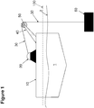
- FIGS 1 and 2 illustrate examples of the problem heave compensation systems are intended to address.
- a surface ship 1 having a deck 10 floats above a surface of a body of water indicated by a waterline 2.
- the deck 10 is elevated above the waterline 2 and machinery is affixed to it.
- a crane 40 or similar lifting mechanism is configured so as to be able to lift overboard a payload 60 and raise or lower that payload 60 by rope or cable 30 connected on one end to the payload 60 and on the other end to a winch 20.
- the cable 30 passes over an overboard-sheave 50 where the direction of the cable 30 is changed from near horizontal to vertical. When at rest, the tension in cable 30 is nominally equal to the weight of the payload 60 plus the weight of the cable 30 between overboard-sheave 50 and payload 60.
- the ship 1 is raised by wave action above a reference line 100 which it was earlier below as shown in Figure 1 . This happens over a finite period of time wherein the ship 1, and more specifically, the overboard-sheave 50, is accelerated upward.
- the ship 1 resists this acceleration by settling deeper in the water as indicated by the waterline 2 nearer the deck.
- the payload 60 also resists this acceleration because of gravity acting on its own mass plus the drag force of the water acting on the payload 60 once in motion.
- the tension in cable 30 is thereby increased until the vertical velocity of the payload 60 is equal to or exceeds the velocity of overboard-sheave 50.
- the increased tension in cable 30 can be extreme and introduces loads on all components of the system including the deck 10, the winch 20, the crane 40, the overboard-sheave 50, as well as the payload 60.
- the entire system must be engineered to withstand the forces that will act on it given a particular sea state defining the safe operating window; otherwise, one or another system component will fail, endangering the mission, equipment, personnel, and/or payload.
- Heave may be defined as the vertical motion of the overboard-sheave 50 induced by wave action on the vessel, and heave compensation systems are employed to minimize the effects described above thereby widening the safe operating window for the vessel and its machinery in carrying out its mission.
- FIG. 3 illustrates a conventional example of a passive heave compensation system that is entirely spring based. It is passive because once engaged, it requires no extra energy beyond the energy introduced into the system by the motion of the ship and payloads themselves.
- Deck 10, winch 20, cable 30, overboard-sheave 50, and payload 60 are as illustrated in earlier figures.
- Overboard-sheave 50 is supported by crane 40 (not shown) as before.
- Two sheave-blocks 70 and 80 are separated from each other by a spring 90.
- Sheave block 70 is fixed in place, and may be referred to as a "fixed sheave-block", while sheave-block 80 is movable, and may be referred to as a "flying sheave-block".
- the flying sheave-block 80 optionally moves vertically inside a support structure (not shown) that keep it stably centered over the fixed sheave-block 70.
- the spring 90 is substantially vertically oriented with sheave-blocks 70, 80 aligned one above the other, but horizontal arrangements are possible and common.
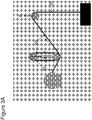
- Figure 3A shows the reaction of machinery in Figure 2 to an upward heave event.
- the upward heave A increases tension on the cable 30 and causes the spring to be compressed, reducing the distance between the sheave-blocks B, and freeing some portion of cable 30 that passes around the sheave-blocks to be released as illustrated.
- reduced tension on the cable 30 will allow the spring to expand, increasing the distance between the sheave-blocks B, which in turn takes up what might otherwise be slack in rope 30.
- the spring constant must be matched to the load, which includes the payload 60 plus the weight of cable 30 between overboard-sheave 50 and the payload 60. If friction is ignored, the passive system just described is closely analogous to a spring 70 inserted in rope 30 between overboard-sheave 50 and the payload as illustrated in Figure 4 .
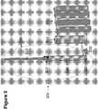
- a gas spring 200 consists of a piston 210 free to move inside a piston housing 220, with a bottom seal 230.
- the piston has seals 211 that prevent gas from passing between the piston 210 and piston housing 220.
- At the bottom of the piston housing 220 there is plumbing that allows gas to pass freely between the piston assembly 239 and an accumulator 240.
- the volume inside the piston housing 220 below the piston seals 211 together with volume inside the accumulator 240 constitutes a pressure vessel.
- the volume of the pressure vessel is further increased by plumbing in a series of gas bottles 250.
- the gas is typically nitrogen or air, but other gases may be utilized.
- the gas is typically nitrogen or air, but other gases may be utilized.
- the spring constant of the system is adjusted by varying the pressure inside the gas filled portion of the gas spring 200 relying on Boyles Law, where pressure p multiplied by volume v is a constant.
- the fully pneumatic spring of Figure 5 represents a passive heave spring but typically a combination gas-over-fluid spring, as illustrated in Figure 6 is used for reasons unimportant to this discussion.
- the piston housing 220 is filled with fluid 241 beneath the piston seals 211, as is a substantial portion of the accumulator 242 and the plumbing 235 connecting the two.
- the piston 210 is advanced into the piston housing 220, instead of compressing gas directly, it displaces hydraulic fluid into the bottom of the accumulator.
- the gas-fluid interface 243 is inside the accumulator 240. As the level of fluid in the accumulator 240 is increased, it compresses the gas in the upper portion of the accumulator 240 and the remainder of the pressure vessel in just the same manner that the piston itself would in the all pneumatic version of Fig. 5 .
- the spring constant in a gas spring is easily adjusted by changing the pressure in the pressure vessel.
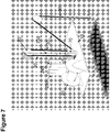
- Figure 7 shows the principle components of a gas spring in a passive heave compensation system as discussed.
- the system illustrated and discussed herein above had a single pneumatic or hydraulic piston, but there can be more than one piston (often two) between the flying sheave-block 80 and the fixed sheave-block 70 usually feeding the same accumulator 240.
- Passive heave compensation systems based on gas springs are widely used, simple, and very effective at insulating cable 30 from extreme fluctuations in tension.
- the spring only responds to changes in the tension of rope 30 at the overboard sheave 50, and any change in this tension will cause the payload 60 to be displaced vertically in the water column. That tension is nominally equal to the weight in water of the payload 60 plus the weight in water of the rope 30 between the overboard sheave 50 and the payload 60.
- This can be defined as "active-load” and is a largely invariant physical property of payload 60, rope 30, and the earth's gravity.
- the weight-on-sheave (WOS) at the overboard sheave 50 will nominally be equal to the active-load.
- the WOS is sensitive to heave due to the payload's inertia and the drag forces acting on the payload 60 and rope 30. If the WOS at overboard sheave 50 exceeds the active-load, the payload 60 will be lifted in the water column. And if the WOS at overboard sheave 50 is below the active-load, the payload 60 will fall in the water column.
- the spring cannot respond until the differential tension is sufficient to overcome the friction in the system components, which can be significant.
- cable 30 is likely a relatively large wire rope, synthetic rope, or armor shielded umbilical. Such ropes and cables do not bend easily over a sheave and once bent, resist counter deformation.
- MRU motion reference unit
- active systems that incorporate passive systems as described hereinabove.
- the active system provides power assist (usually hydraulic) to override the motion of the flying sheave-block 80.
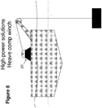
- Such systems are called active-over-passive (AOP) systems as diagramed in Figures 10 and 11 .
- Figure 10 is different diagrammatically but operationally identical to passive gas-spring compensation systems as already discussed.
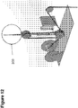
- Figures 11 and 12 show the addition of a hydraulically implemented active override 300.
- the spring is doing the lion's share of the work just as it did acting alone passively. The only extra force required is that needed to overcome friction in the system, the energy stored in the spring when displaced from its neutral set-point, and the inertia in the moving parts.
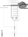
- FIG 13 shows a block diagram of the active-over-passive system described.
- the motion of the vessel is monitored by a motion reference unit (MRU).
- MRU motion reference unit
- PLC programmable logic controller
- the PLC then directs hydraulic fluid to actuate the hydraulic cylinder in the appropriate direction.
- the actual motion is fed back to the PLC from a measuring device.
- the active portion of the system as described is implemented with a hydraulic cylinder but those skilled in the art will recognize other mechanisms could be used to add the necessary energy, such as, e.g., a motor driving a rack and pinion.
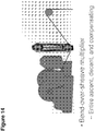
- Figure 14 depicts another shortcoming with gas-spring compensation systems, whether active or passive.
- the lift line carrying the payload being compensated traverses all the sheaves of the gas spring. This is true not just when compensating, but for the entire ascent and descent from the vessel to the final operating depth. At each sheave the rope or wire bends over that sheave causing wear.
- inline compensation, " and all inline compensators are bend-over-sheave (BOS) multipliers.
- the lift line, whether wire or new synthetic fiber may be three or more miles long in marine operations, for example, and cost in excess of $150,000; thus wear and deterioration of the rope is a serious matter even without considering the value of the payload connected to the vessel by this single thread. It is also difficult to monitor the condition of the rope over its entire length during routine operations.
- An embodiment of the invention is a payload control apparatus that includes a spring-line assembly, including a spring line actuating mechanism, a spring-line flying sheave assembly including a flying sheave over which a load line can pass, and a spring line having one end connected to the spring line actuating mechanism and another end connected to the spring line flying sheave assembly, wherein the spring line flying sheave assembly can be moveably disposed via the spring line actuating mechanism into at least one position such that the flying sheave is in either a non-contacting, spaced relation or a non-path-altering, contacting relation to a region of the load line having a straight load-line path length, L 1 , in local proximity to the flying sheave, wherein the load-line is connected at one region thereof to a winch assembly and at another region thereof to a payload to be controllably lifted, lowered, positioned, or maintained in a stationary location, further wherein the spring-line flying sheave assembly can be moveably disposed via the actuating mechanism
- the payload control apparatus may further include or be further characterized by the following features or limitations:
- An embodiment of the invention is a method for controlling a payload that is desired to be raised, lowered, positioned, or maintained in a position in an unstable medium.
- the method includes the steps of providing a payload attached to a load-line having a locally straight load-line path and providing a payload control apparatus as described hereinabove; and utilizing the payload control apparatus stabilize the payload in the unstable medium.
- the unstable medium is water.
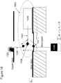
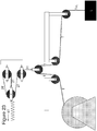
- FIG. 15 An embodiment of a payload control apparatus 1000 is illustrated in Fig. 15 .
- the apparatus is in an unengaged state.
- a winch 1020, load 1060, and an upper deck and main deck of a marine vessel are illustrated, they do not form a part of the invention per se ; rather, they assist in illustrating the operation of the invention.
- the apparatus 1000 includes a spring-line assembly 1002, including a spring line actuating mechanism 1005, a spring-line flying sheave assembly 1006 including a flying sheave 1006-1 over which a load line (1030) can pass; and a spring line 1004 having a second end 1004-2 connected to the spring line actuating mechanism and a first end 1004-1 connected to the spring line flying sheave assembly 1006.
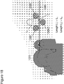
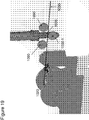
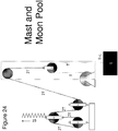
- the spring line flying sheave assembly 1006 can be moveably disposed via the spring line actuating mechanism into at least one position such that the flying sheave 1006-1 is either in a non-contacting, spaced relation with a section of the load line 1030 (see Fig.
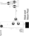
- the spring-line flying sheave assembly 1006 further can be moveably disposed via the actuating mechanism into at least another position such that the flying sheave 1006-1 is in a path-altering, engaging contact position (see Fig. 16 ) with the region of the straight load-line path of the load-line (also Fig.
- the spring-line assembly 1002 includes a spring line actuating mechanism 1005 in the form of a gas spring 1008, which includes fixed and moveable sheaves separated by the spring 1008 (pneumatic, hydra-pneumatic, etc.).
- the figures further illustrate a flying sheave assembly guiding member 1070 within which the flying sheave assembly 1006 (and the connected flying sheave 1006-1) can controllably move in a linear direction.
- fixed sheaves 1090 may, but need not be in operational contact with the load line 1030 when the apparatus is unengaged and non-path-altering.
- the flying sheave assembly may include an active compensator assembly 1080 operably coupled to the guiding structure and the spring-line flying sheave assembly.
- the active compensator includes a motion feedback control component of sensors and computational devices (not shown) controlling the motorized rack and pinion assembly 1080.
- the active compensator may also or alternatively comprise a hydraulic cylinder, a pneumatic cylinder, or a third driven line (not shown) to assist the motion of the flying sheave.
- the spring line actuating machinery 1005 may be oriented as needed or convenient anywhere on the vessel.
- the spring line can have a nominal length of less than 200 feet, since it need only be long enough to extend from the flying sheave assembly 1006 and about the actuating machinery to compensate for gross heave distances in the unstable medium.
- the spring line can be easily inspected and replaced if necessary, and be made arbitrarily strong.
- the relatively long, heavy, expensive, and unwieldy load line is not required to, and does not traverse the sheaves of the gas-spring 1008 doing most of the heave compensation work.
- the spring line actuating mechanism e.g., gas spring
- N 3, 4, 5, 6, respectively
- the arrangement of components including added optional fixed sheaves 1090 is nearly limitless.
- a reference to "A and/or B", when used in conjunction with open-ended language such as “comprising” can refer, in one embodiment, to A only (optionally including elements other than B); in another embodiment, to B only (optionally including elements other than A); in yet another embodiment, to both A and B (optionally including other elements); etc.
- the phrase "at least one,” in reference to a list of one or more elements, should be understood to mean at least one element selected from any one or more of the elements in the list of elements, but not necessarily including at least one of each and every element specifically listed within the list of elements and not excluding any combinations of elements in the list of elements.
- This definition also allows that elements may optionally be present other than the elements specifically identified within the list of elements to which the phrase "at least one" refers, whether related or unrelated to those elements specifically identified.
- At least one of A and B can refer, in one embodiment, to at least one, optionally including more than one, A, with no B present (and optionally including elements other than B); in another embodiment, to at least one, optionally including more than one, B, with no A present (and optionally including elements other than A); in yet another embodiment, to at least one, optionally including more than one, A, and at least one, optionally including more than one, B (and optionally including other elements); etc.
Landscapes
- Engineering & Computer Science (AREA)
- Mechanical Engineering (AREA)
- Automation & Control Theory (AREA)
- Chemical & Material Sciences (AREA)
- Combustion & Propulsion (AREA)
- Ocean & Marine Engineering (AREA)
- Earth Drilling (AREA)
- Vibration Prevention Devices (AREA)
- Pulleys (AREA)
- Springs (AREA)
- Electric Cable Arrangement Between Relatively Moving Parts (AREA)
- Jib Cranes (AREA)
- Vibration Dampers (AREA)
- Carriers, Traveling Bodies, And Overhead Traveling Cranes (AREA)
- Geophysics And Detection Of Objects (AREA)
- Transmission Devices (AREA)
Claims (14)
- Appareil de contrôle de charge utile (1000), comprenant :
un ensemble de garde montante (1002), comprenant :un mécanisme d'actionnement de garde montante (1005) ;un ensemble de poulie volante de garde montante (1006) comprenant une seule poulie volante (1006-1) sur laquelle une ligne de charge (1030) peut passer ; etune garde montante flexible (1004) ayant une extrémité (1004-2) reliée au mécanisme d'actionnement de garde montante (1005) et une autre extrémité (1004-1) reliée à l'ensemble de poulie volante de garde montante (1006),dans lequel l'ensemble de poulie volante de garde montante (1006) peut être disposé de manière mobile via le mécanisme d'actionnement de garde montante (1005) dans au moins une position de sorte que la poulie volante (1006-1) se trouve dans l'une d'une relation espacée sans contact et d'une relation avec contact qui ne modifie pas le trajet par rapport à une zone d'un trajet de ligne de charge droit ayant une longueur de trajet de ligne de charge, L1, de la ligne de charge qui est reliée, au niveau d'une zone de celle-ci, à un ensemble de treuil (1020) et, au niveau d'une autre zone de celle-ci, à une charge utile (1060) qui doit être soulevée, abaissée, positionnée ou maintenue à un emplacement stationnaire de manière contrôlable, etune ou plusieurs poulies rotatives et positionnées de manière fixe disposées sur le trajet de ligne de charge,dans lequel la ou les poulies fixes assurent une stabilisation de trajet de ligne de charge lorsque la poulie volante d'ensemble de garde montante est disposée dans la position de modification de trajet et avec contact d'engagement avec la ligne de charge,
dans lequel, en outre, l'ensemble de poulie volante de garde montante (1006) peut être disposé de manière mobile, via le mécanisme d'actionnement, dans au moins une autre position de sorte que la poulie volante (1006-1) se trouve en contact d'engagement à modification de trajet de ligne de charge avec la zone du trajet de ligne de charge droit de la ligne de charge de sorte que le trajet de ligne de charge ne soit pas droit et présente une longueur de trajet de ligne de charge, L2, supérieure à la longueur de trajet de ligne de charge L1. - Appareil selon la revendication 1, dans lequel la charge et au moins une partie de la ligne de charge sont disposées dans une colonne d'eau.
- Appareil selon la revendication 1, dans lequel ΔL = L2 - L1 est variable de manière contrôlable.
- Appareil selon la revendication 1, dans lequel l'ensemble de garde montante (1002) comprend en outre une structure de guidage d'ensemble de poulie volante de garde montante qui offre un trajet d'ensemble de poulie volante sur lequel la poulie volante d'ensemble de garde montante est disposée de manière mobile de façon à orienter le mouvement de la poulie volante (1006-1) le long du trajet de poulie.
- Appareil selon la revendication 4, comprenant en outre un compensateur actif relié fonctionnellement à la structure de guidage et à la poulie d'ensemble de garde montante.
- Appareil selon la revendication 5, dans lequel le compensateur actif comprend un composant de commande de retour de mouvement et au moins l'un d'un ensemble de rack motorisé et de pignon, d'un vérin hydraulique, d'un vérin pneumatique, et d'une troisième ligne entraînée.
- Appareil selon la revendication 1, dans lequel le mécanisme d'actionnement de garde montante (1005) comprend un ressort et au moins une poulie rotative et mobile sur laquelle agit le ressort.
- Appareil selon la revendication 7, dans lequel le ressort est un ressort pneumatique.
- Appareil selon la revendication 7, dans lequel le ressort est un ressort hydropneumatique.
- Appareil selon la revendication 1, dans lequel le mécanisme d'actionnement de garde montante (1005) comprend un dispositif de compensation de hissage passif sous n'importe quelle forme.
- Appareil selon la revendication 1, dans lequel l'extrémité (1004-2) de la garde montante (1004) est fixée sur une partie immobile du mécanisme d'actionnement de garde montante (1005).
- Appareil selon la revendication 7, dans lequel l'extrémité (1004-2) de la garde montante (1004) est fixée sur la au moins une poulie mobile du mécanisme d'actionnement de garde montante (1005).
- Procédé de contrôle d'une charge utile (1060) qui doit être soulevée, abaissée, positionnée ou maintenue dans une position dans un milieu instable, comprenant les étapes consistant à :prévoir une charge utile (1060) reliée à une ligne de charge utile ayant un trajet de ligne de charge utile droit ayant une longueur L1 ;prévoir un ensemble de garde montante (1002) comprenant :un mécanisme d'actionnement ;une garde montante flexible ayant une zone reliée au mécanisme d'actionnement et une autre zone reliée à un seul ensemble de garde montante à poulie volante (1002) ; etune poulie volante d'ensemble de garde montante qui peut être disposée de manière mobile, via le mécanisme d'actionnement, dans au moins une première position de sorte que la poulie se trouve dans l'une d'une relation espacée sans contact et d'une relation avec contact qui ne modifie pas le trajet par rapport à une zone du trajet de ligne de charge utile droit, dans lequel la poulie de l'ensemble de garde montante peut être disposée de manière mobile, via le mécanisme d'actionnement, dans au moins une seconde position de sorte que la poulie se trouve en contact d'engagement à modification de trajet avec la zone du trajet de ligne de charge utile droit ;prévoir une ou plusieurs poulies rotatives et positionnées de manière fixe disposées sur le trajet de ligne de charge, moyennant quoi la ou les poulies fixes assurent une stabilisation de trajet de ligne de charge lorsque la poulie volante d'ensemble de garde montante est disposée dans la position de modification de trajet et avec contact d'engagement avec la ligne de charge ; etle déplacement de la poulie d'ensemble de garde montante à l'aide du mécanisme d'actionnement entre la première position et la seconde position afin de modifier le trajet de ligne de charge utile de sorte qu'il ne soit pas droit et qu'il possède une longueur L2 supérieure à L1.
- Procédé selon la revendication 13, dans lequel le milieu est de l'eau.
Applications Claiming Priority (2)
| Application Number | Priority Date | Filing Date | Title |
|---|---|---|---|
| US201261714792P | 2012-10-17 | 2012-10-17 | |
| PCT/US2013/065225 WO2014062792A1 (fr) | 2012-10-17 | 2013-10-16 | Appareil de gestion d'une charge utile, procédé et applications |
Publications (3)
| Publication Number | Publication Date |
|---|---|
| EP2909128A1 EP2909128A1 (fr) | 2015-08-26 |
| EP2909128A4 EP2909128A4 (fr) | 2016-06-15 |
| EP2909128B1 true EP2909128B1 (fr) | 2019-07-31 |
Family
ID=50488725
Family Applications (1)
| Application Number | Title | Priority Date | Filing Date |
|---|---|---|---|
| EP13847441.6A Not-in-force EP2909128B1 (fr) | 2012-10-17 | 2013-10-16 | Appareil de gestion d'une charge utile, procédé et applications |
Country Status (10)
| Country | Link |
|---|---|
| US (1) | US9834417B2 (fr) |
| EP (1) | EP2909128B1 (fr) |
| CN (1) | CN104903227B (fr) |
| AU (1) | AU2013331342B2 (fr) |
| BR (1) | BR112015008677B1 (fr) |
| CA (1) | CA2888446C (fr) |
| MX (1) | MX356405B (fr) |
| NZ (1) | NZ707032A (fr) |
| RU (1) | RU2641390C2 (fr) |
| WO (1) | WO2014062792A1 (fr) |
Families Citing this family (14)
| Publication number | Priority date | Publication date | Assignee | Title |
|---|---|---|---|---|
| US20150129529A1 (en) * | 2013-11-13 | 2015-05-14 | Lee David Screaton | Marine lifting apparatus |
| US10246950B2 (en) * | 2015-02-05 | 2019-04-02 | Nabors Drilling Technologies Usa, Inc. | Deadline compensator |
| GB2538986A (en) * | 2015-06-02 | 2016-12-07 | Marine Electrical Consulting Ltd | Method and apparatus for adaptive motion compensation |
| US9630814B2 (en) * | 2015-07-14 | 2017-04-25 | Arthur Southerland, JR. | System and apparatus for motion compensation and anti-pendulation |
| DE102016005477A1 (de) * | 2016-05-03 | 2017-11-09 | Hycom B.V. | Ausgleichsvorrichtung zum Beibehalten von vorgebbaren Soll-Positionen einer handhabbaren Last |
| US10042067B1 (en) * | 2017-09-25 | 2018-08-07 | The United States Of America As Represented By The Secretary Of The Navy | Safety system for a towed source |
| US10669137B2 (en) * | 2017-09-25 | 2020-06-02 | Wt Industries, Llc | Heave compensation system |
| JP6565123B2 (ja) * | 2017-11-10 | 2019-08-28 | ウラカミ合同会社 | オートテンション機能を有するウインチ装置 |
| DE202018101068U1 (de) * | 2018-02-27 | 2019-06-06 | Zasche handling GmbH | Elektrisches Balancier-Hebezeug |
| CN108992080B (zh) * | 2018-05-31 | 2022-05-10 | 东软医疗系统股份有限公司 | 重力平衡机构 |
| EP3708528B1 (fr) * | 2019-03-12 | 2021-10-13 | BAUER Maschinen GmbH | Machine de travail et procédé de fonctionnement de la machine de travail |
| NO346752B1 (en) | 2019-07-04 | 2022-12-12 | Newtech As | A floating foundation for an offshore wind turbine, a system for extracting energy from wind, and a method of installing a wind turbine |
| CN112270865B (zh) * | 2020-10-12 | 2021-08-27 | 浙江大学 | 一种基于弹簧模组加载的大飞机驾驶盘模拟装置 |
| CN117819148A (zh) * | 2024-01-22 | 2024-04-05 | 中船黄埔文冲船舶有限公司 | 海底矿物运输装置 |
Family Cites Families (38)
| Publication number | Priority date | Publication date | Assignee | Title |
|---|---|---|---|---|
| US943509A (en) * | 1908-04-20 | 1909-12-14 | Otto Adam | Electrical cableway system. |
| US1281323A (en) * | 1917-04-06 | 1918-10-15 | Bucyrus Co | Anchorage for excavator track-lines. |
| US1592828A (en) * | 1924-01-01 | 1926-07-20 | Gray Arthur Gerald | Derrick or crane |
| DE1107311B (de) * | 1956-11-27 | 1961-05-25 | Telegraph Constr & Maintenance | Verfahren und Vorrichtung zum Regeln der Bewegung eines Seekabels beim Auslegen oderEinholen |
| NL139703B (nl) * | 1968-08-12 | 1973-09-17 | Ihc Holland Nv | Inrichting voor het op woelig water, zoals op zee, hanteren van een last ten opzichte van een bepaald punt. |
| US3653635A (en) * | 1969-11-17 | 1972-04-04 | Joe Stine Inc | Wave motion compensating apparatus for use with floating hoisting systems |
| CA961477A (en) * | 1971-03-02 | 1975-01-21 | Compagnie Francaise Des Petroles | Dispositif d'antipilonnement monte sur une embarcation pour le maintien d'un cable a un niveau donne au-dessus d'un fond subaquatique |
| US3785445A (en) | 1972-05-01 | 1974-01-15 | J Scozzafava | Combined riser tensioner and drill string heave compensator |
| US3894582A (en) * | 1972-06-08 | 1975-07-15 | Kammerer Jr Archer W | Slack removal apparatus |
| FR2344490A1 (fr) | 1976-03-18 | 1977-10-14 | Elf Aquitaine | Dispositif de compensation des variations de distance entre un objet flottant sur l'eau et le fond de celle-ci |
| NL169711C (nl) * | 1977-06-01 | 1982-08-16 | Ihc Holland Nv | Inrichting voor het constant houden van de trekspanning in een kabel. |
| US4157812A (en) * | 1977-08-15 | 1979-06-12 | Bunker Ramo Corporation | Ship motion compensator for recovery of oceanographic instrumentation |
| GB2045196B (en) * | 1979-03-31 | 1982-12-08 | Ferranti Ltd | Cable tensioning device |
| US4522285A (en) * | 1983-10-20 | 1985-06-11 | Otis Elevator Company | Hydraulic tie-down for elevators |
| DE3546277A1 (de) * | 1985-12-28 | 1987-07-02 | Bomag Menck Gmbh | Kompensatorvorrichtung |
| US5190107A (en) | 1991-04-23 | 1993-03-02 | Shell Oil Company | Heave compensated support system for positioning subsea work packages |
| US5894895A (en) | 1996-11-25 | 1999-04-20 | Welsh; Walter Thomas | Heave compensator for drill ships |
| US6082947A (en) * | 1999-08-17 | 2000-07-04 | Adamson; James E. | Coordinated motion marine lifting device |
| AU6372599A (en) | 1999-10-19 | 2001-04-30 | Huisman Special Lifting Equipment B.V. | Hoisting mechanism, with compensator installed in a hoisting cable system |
| US6926103B1 (en) | 2001-07-02 | 2005-08-09 | Itrec B.V. | Splittable block on a derrick |
| US6926259B1 (en) | 2003-03-12 | 2005-08-09 | Itrec B.V. | Hoist system |
| JP2004332890A (ja) | 2003-05-12 | 2004-11-25 | Mitsui Eng & Shipbuild Co Ltd | 上下動補償機能付巻上げ装置 |
| US7231981B2 (en) | 2003-10-08 | 2007-06-19 | National Oilwell, L.P. | Inline compensator for a floating drill rig |
| US6935262B2 (en) * | 2004-01-28 | 2005-08-30 | Itrec B.V. | Method for lowering an object to an underwater installation site using an ROV |
| GB0406336D0 (en) | 2004-03-19 | 2004-04-21 | Subsea 7 Uk | Apparatus and method |
| WO2006007562A2 (fr) | 2004-07-01 | 2006-01-19 | Cudd Pressure Control, Inc. | Systeme et procede de freinage a pilonnement compense |
| US7191837B2 (en) | 2004-07-20 | 2007-03-20 | Coles Robert A | Motion compensator |
| EP1795491B1 (fr) * | 2005-12-07 | 2011-01-05 | IHC Holland IE N.V. | Méthode pour transférer une charge entre objects soumis à la houle, et dispositif de compensation de houle |
| EP2029423B1 (fr) * | 2006-06-16 | 2009-12-23 | Itrec B.V. | Compensation du mouvement de tangage |
| EP2054335B1 (fr) | 2006-08-15 | 2012-04-04 | Hydralift Amclyde, Inc. | Compensateur actif direct de mouvement de tangage actif/passif à poulie unique |
| US7389973B1 (en) * | 2007-02-15 | 2008-06-24 | Samson Rope Technologies | Tensioning systems and methods for line spooling |
| GB0705110D0 (en) * | 2007-03-16 | 2007-04-25 | Lewis Ltd | Wireline intervention system |
| US7934561B2 (en) | 2007-04-10 | 2011-05-03 | Intermoor, Inc. | Depth compensated subsea passive heave compensator |
| WO2009120062A2 (fr) * | 2008-03-26 | 2009-10-01 | Itrec B.V. | Système et procédé de compensation de pilonnement |
| CN102630211B (zh) | 2009-09-18 | 2015-04-15 | 伊特里克公司 | 升降设备 |
| BR112012030605A2 (pt) | 2010-06-02 | 2019-09-24 | Itrec Bv | sistema de elevação ou abaixamento de carga marinho para uso em uma embarcação, e, método para abaixar uma carga a partir de uma embarcação |
| HRP20150614T1 (hr) | 2011-03-23 | 2015-07-17 | Flamek Ltd | Uređaj za zatezanje užeta |
| NO334789B1 (no) | 2011-04-04 | 2014-05-26 | Rolls Royce Marine As | Anordning for spenning av et tau eller en kabel |
-
2013
- 2013-10-16 RU RU2015114168A patent/RU2641390C2/ru active
- 2013-10-16 US US14/436,105 patent/US9834417B2/en not_active Expired - Fee Related
- 2013-10-16 EP EP13847441.6A patent/EP2909128B1/fr not_active Not-in-force
- 2013-10-16 MX MX2015004860A patent/MX356405B/es active IP Right Grant
- 2013-10-16 CA CA2888446A patent/CA2888446C/fr active Active
- 2013-10-16 NZ NZ707032A patent/NZ707032A/en not_active IP Right Cessation
- 2013-10-16 BR BR112015008677-2A patent/BR112015008677B1/pt not_active IP Right Cessation
- 2013-10-16 AU AU2013331342A patent/AU2013331342B2/en not_active Ceased
- 2013-10-16 WO PCT/US2013/065225 patent/WO2014062792A1/fr not_active Ceased
- 2013-10-16 CN CN201380062338.3A patent/CN104903227B/zh not_active Expired - Fee Related
Non-Patent Citations (1)
| Title |
|---|
| None * |
Also Published As
| Publication number | Publication date |
|---|---|
| US20150266704A1 (en) | 2015-09-24 |
| EP2909128A1 (fr) | 2015-08-26 |
| RU2641390C2 (ru) | 2018-01-17 |
| CA2888446A1 (fr) | 2014-04-24 |
| EP2909128A4 (fr) | 2016-06-15 |
| MX356405B (es) | 2018-05-25 |
| NZ707032A (en) | 2017-01-27 |
| RU2015114168A (ru) | 2016-12-10 |
| MX2015004860A (es) | 2016-01-12 |
| CA2888446C (fr) | 2020-10-27 |
| AU2013331342A1 (en) | 2015-05-07 |
| BR112015008677B1 (pt) | 2021-07-27 |
| CN104903227A (zh) | 2015-09-09 |
| US9834417B2 (en) | 2017-12-05 |
| WO2014062792A1 (fr) | 2014-04-24 |
| BR112015008677A2 (pt) | 2017-07-04 |
| AU2013331342B2 (en) | 2016-11-10 |
| CN104903227B (zh) | 2018-01-26 |
Similar Documents
| Publication | Publication Date | Title |
|---|---|---|
| US9834417B2 (en) | Payload control apparatus, method, and applications | |
| EP2477927B1 (fr) | Dispositif de levage | |
| US7543799B2 (en) | Method and apparatus for deploying articles in deep waters | |
| DK2896589T3 (en) | Method and apparatus. | |
| EP2694427B1 (fr) | Dispositif de tensionnement | |
| US8414241B2 (en) | Device and method for lowering or lifting a load in water | |
| EP2986550B1 (fr) | Appareil porte-charge et procédé | |
| US8905381B2 (en) | Hoisting assembly | |
| CN111566003B (zh) | 防护件吊架装置 | |
| AU2012328226A1 (en) | Introduction or withdrawal of an elongate member to or from a body | |
| US20170327192A1 (en) | Offshore lifting of a load with heave compensation | |
| EP3854746B1 (fr) | Système de levage et procédé de levage d'un objet suspendu verticalement | |
| EP3363989A1 (fr) | Unité de forage comprenant un système de compensation de pilonnement électrique | |
| NL1037953C2 (en) | Heave compensated chute. | |
| GB2501282A (en) | Emergency auxiliary lifting apparatus for use with winches on ships | |
| WO2013073950A1 (fr) | Navire et procédé de remorquage d'une charge lourde sous-marin | |
| SU1020341A1 (ru) | Подъемна установка | |
| RU2814109C1 (ru) | Комплекс для спуска и подъема оборудования для добычи полезных ископаемых со дна морей | |
| CN113784887A (zh) | 用于执行海底钻井孔相关活动的海上系统、船和方法 | |
| EP2576412A1 (fr) | Équipement pour commander une charge | |
| EP3513106B1 (fr) | Système, appareil et procédé | |
| KR20250137672A (ko) | 선미 롤러 장치 | |
| WO2024153668A1 (fr) | Système de grue comprenant un treuil de remorquage et une ligne de remorquage |
Legal Events
| Date | Code | Title | Description |
|---|---|---|---|
| PUAI | Public reference made under article 153(3) epc to a published international application that has entered the european phase |
Free format text: ORIGINAL CODE: 0009012 |
|
| 17P | Request for examination filed |
Effective date: 20150517 |
|
| AK | Designated contracting states |
Kind code of ref document: A1 Designated state(s): AL AT BE BG CH CY CZ DE DK EE ES FI FR GB GR HR HU IE IS IT LI LT LU LV MC MK MT NL NO PL PT RO RS SE SI SK SM TR |
|
| AX | Request for extension of the european patent |
Extension state: BA ME |
|
| DAX | Request for extension of the european patent (deleted) | ||
| RA4 | Supplementary search report drawn up and despatched (corrected) |
Effective date: 20160513 |
|
| RIC1 | Information provided on ipc code assigned before grant |
Ipc: B66C 13/02 20060101ALI20160509BHEP Ipc: B66C 13/18 20060101AFI20160509BHEP Ipc: B66D 1/52 20060101ALI20160509BHEP Ipc: B66C 13/10 20060101ALI20160509BHEP |
|
| REG | Reference to a national code |
Ref country code: DE Ref legal event code: R079 Ref document number: 602013058600 Country of ref document: DE Free format text: PREVIOUS MAIN CLASS: B66D0003040000 Ipc: B63B0027160000 |
|
| RIC1 | Information provided on ipc code assigned before grant |
Ipc: B66C 13/10 20060101ALI20181213BHEP Ipc: B66D 1/52 20060101ALI20181213BHEP Ipc: B66C 13/18 20060101ALI20181213BHEP Ipc: B66C 13/02 20060101ALI20181213BHEP Ipc: B63B 27/16 20060101AFI20181213BHEP |
|
| GRAP | Despatch of communication of intention to grant a patent |
Free format text: ORIGINAL CODE: EPIDOSNIGR1 |
|
| STAA | Information on the status of an ep patent application or granted ep patent |
Free format text: STATUS: GRANT OF PATENT IS INTENDED |
|
| INTG | Intention to grant announced |
Effective date: 20190131 |
|
| GRAS | Grant fee paid |
Free format text: ORIGINAL CODE: EPIDOSNIGR3 |
|
| GRAJ | Information related to disapproval of communication of intention to grant by the applicant or resumption of examination proceedings by the epo deleted |
Free format text: ORIGINAL CODE: EPIDOSDIGR1 |
|
| GRAL | Information related to payment of fee for publishing/printing deleted |
Free format text: ORIGINAL CODE: EPIDOSDIGR3 |
|
| STAA | Information on the status of an ep patent application or granted ep patent |
Free format text: STATUS: REQUEST FOR EXAMINATION WAS MADE |
|
| GRAR | Information related to intention to grant a patent recorded |
Free format text: ORIGINAL CODE: EPIDOSNIGR71 |
|
| STAA | Information on the status of an ep patent application or granted ep patent |
Free format text: STATUS: GRANT OF PATENT IS INTENDED |
|
| GRAA | (expected) grant |
Free format text: ORIGINAL CODE: 0009210 |
|
| STAA | Information on the status of an ep patent application or granted ep patent |
Free format text: STATUS: THE PATENT HAS BEEN GRANTED |
|
| INTC | Intention to grant announced (deleted) | ||
| AK | Designated contracting states |
Kind code of ref document: B1 Designated state(s): AL AT BE BG CH CY CZ DE DK EE ES FI FR GB GR HR HU IE IS IT LI LT LU LV MC MK MT NL NO PL PT RO RS SE SI SK SM TR |
|
| INTG | Intention to grant announced |
Effective date: 20190625 |
|
| REG | Reference to a national code |
Ref country code: CH Ref legal event code: EP Ref country code: GB Ref legal event code: FG4D |
|
| REG | Reference to a national code |
Ref country code: DE Ref legal event code: R096 Ref document number: 602013058600 Country of ref document: DE |
|
| REG | Reference to a national code |
Ref country code: AT Ref legal event code: REF Ref document number: 1160604 Country of ref document: AT Kind code of ref document: T Effective date: 20190815 |
|
| REG | Reference to a national code |
Ref country code: IE Ref legal event code: FG4D |
|
| REG | Reference to a national code |
Ref country code: NO Ref legal event code: T2 Effective date: 20190731 |
|
| REG | Reference to a national code |
Ref country code: NL Ref legal event code: MP Effective date: 20190731 |
|
| REG | Reference to a national code |
Ref country code: LT Ref legal event code: MG4D |
|
| REG | Reference to a national code |
Ref country code: AT Ref legal event code: MK05 Ref document number: 1160604 Country of ref document: AT Kind code of ref document: T Effective date: 20190731 |
|
| PG25 | Lapsed in a contracting state [announced via postgrant information from national office to epo] |
Ref country code: PT Free format text: LAPSE BECAUSE OF FAILURE TO SUBMIT A TRANSLATION OF THE DESCRIPTION OR TO PAY THE FEE WITHIN THE PRESCRIBED TIME-LIMIT Effective date: 20191202 Ref country code: FI Free format text: LAPSE BECAUSE OF FAILURE TO SUBMIT A TRANSLATION OF THE DESCRIPTION OR TO PAY THE FEE WITHIN THE PRESCRIBED TIME-LIMIT Effective date: 20190731 Ref country code: BG Free format text: LAPSE BECAUSE OF FAILURE TO SUBMIT A TRANSLATION OF THE DESCRIPTION OR TO PAY THE FEE WITHIN THE PRESCRIBED TIME-LIMIT Effective date: 20191031 Ref country code: SE Free format text: LAPSE BECAUSE OF FAILURE TO SUBMIT A TRANSLATION OF THE DESCRIPTION OR TO PAY THE FEE WITHIN THE PRESCRIBED TIME-LIMIT Effective date: 20190731 Ref country code: AT Free format text: LAPSE BECAUSE OF FAILURE TO SUBMIT A TRANSLATION OF THE DESCRIPTION OR TO PAY THE FEE WITHIN THE PRESCRIBED TIME-LIMIT Effective date: 20190731 Ref country code: NL Free format text: LAPSE BECAUSE OF FAILURE TO SUBMIT A TRANSLATION OF THE DESCRIPTION OR TO PAY THE FEE WITHIN THE PRESCRIBED TIME-LIMIT Effective date: 20190731 Ref country code: HR Free format text: LAPSE BECAUSE OF FAILURE TO SUBMIT A TRANSLATION OF THE DESCRIPTION OR TO PAY THE FEE WITHIN THE PRESCRIBED TIME-LIMIT Effective date: 20190731 Ref country code: LT Free format text: LAPSE BECAUSE OF FAILURE TO SUBMIT A TRANSLATION OF THE DESCRIPTION OR TO PAY THE FEE WITHIN THE PRESCRIBED TIME-LIMIT Effective date: 20190731 |
|
| PG25 | Lapsed in a contracting state [announced via postgrant information from national office to epo] |
Ref country code: IS Free format text: LAPSE BECAUSE OF FAILURE TO SUBMIT A TRANSLATION OF THE DESCRIPTION OR TO PAY THE FEE WITHIN THE PRESCRIBED TIME-LIMIT Effective date: 20191130 Ref country code: LV Free format text: LAPSE BECAUSE OF FAILURE TO SUBMIT A TRANSLATION OF THE DESCRIPTION OR TO PAY THE FEE WITHIN THE PRESCRIBED TIME-LIMIT Effective date: 20190731 Ref country code: AL Free format text: LAPSE BECAUSE OF FAILURE TO SUBMIT A TRANSLATION OF THE DESCRIPTION OR TO PAY THE FEE WITHIN THE PRESCRIBED TIME-LIMIT Effective date: 20190731 Ref country code: ES Free format text: LAPSE BECAUSE OF FAILURE TO SUBMIT A TRANSLATION OF THE DESCRIPTION OR TO PAY THE FEE WITHIN THE PRESCRIBED TIME-LIMIT Effective date: 20190731 Ref country code: GR Free format text: LAPSE BECAUSE OF FAILURE TO SUBMIT A TRANSLATION OF THE DESCRIPTION OR TO PAY THE FEE WITHIN THE PRESCRIBED TIME-LIMIT Effective date: 20191101 Ref country code: RS Free format text: LAPSE BECAUSE OF FAILURE TO SUBMIT A TRANSLATION OF THE DESCRIPTION OR TO PAY THE FEE WITHIN THE PRESCRIBED TIME-LIMIT Effective date: 20190731 |
|
| PG25 | Lapsed in a contracting state [announced via postgrant information from national office to epo] |
Ref country code: TR Free format text: LAPSE BECAUSE OF FAILURE TO SUBMIT A TRANSLATION OF THE DESCRIPTION OR TO PAY THE FEE WITHIN THE PRESCRIBED TIME-LIMIT Effective date: 20190731 |
|
| PG25 | Lapsed in a contracting state [announced via postgrant information from national office to epo] |
Ref country code: PL Free format text: LAPSE BECAUSE OF FAILURE TO SUBMIT A TRANSLATION OF THE DESCRIPTION OR TO PAY THE FEE WITHIN THE PRESCRIBED TIME-LIMIT Effective date: 20190731 Ref country code: DK Free format text: LAPSE BECAUSE OF FAILURE TO SUBMIT A TRANSLATION OF THE DESCRIPTION OR TO PAY THE FEE WITHIN THE PRESCRIBED TIME-LIMIT Effective date: 20190731 Ref country code: RO Free format text: LAPSE BECAUSE OF FAILURE TO SUBMIT A TRANSLATION OF THE DESCRIPTION OR TO PAY THE FEE WITHIN THE PRESCRIBED TIME-LIMIT Effective date: 20190731 Ref country code: EE Free format text: LAPSE BECAUSE OF FAILURE TO SUBMIT A TRANSLATION OF THE DESCRIPTION OR TO PAY THE FEE WITHIN THE PRESCRIBED TIME-LIMIT Effective date: 20190731 Ref country code: IT Free format text: LAPSE BECAUSE OF FAILURE TO SUBMIT A TRANSLATION OF THE DESCRIPTION OR TO PAY THE FEE WITHIN THE PRESCRIBED TIME-LIMIT Effective date: 20190731 |
|
| REG | Reference to a national code |
Ref country code: DE Ref legal event code: R119 Ref document number: 602013058600 Country of ref document: DE |
|
| PG25 | Lapsed in a contracting state [announced via postgrant information from national office to epo] |
Ref country code: SM Free format text: LAPSE BECAUSE OF FAILURE TO SUBMIT A TRANSLATION OF THE DESCRIPTION OR TO PAY THE FEE WITHIN THE PRESCRIBED TIME-LIMIT Effective date: 20190731 Ref country code: CZ Free format text: LAPSE BECAUSE OF FAILURE TO SUBMIT A TRANSLATION OF THE DESCRIPTION OR TO PAY THE FEE WITHIN THE PRESCRIBED TIME-LIMIT Effective date: 20190731 Ref country code: IS Free format text: LAPSE BECAUSE OF FAILURE TO SUBMIT A TRANSLATION OF THE DESCRIPTION OR TO PAY THE FEE WITHIN THE PRESCRIBED TIME-LIMIT Effective date: 20200224 Ref country code: MC Free format text: LAPSE BECAUSE OF FAILURE TO SUBMIT A TRANSLATION OF THE DESCRIPTION OR TO PAY THE FEE WITHIN THE PRESCRIBED TIME-LIMIT Effective date: 20190731 Ref country code: SK Free format text: LAPSE BECAUSE OF FAILURE TO SUBMIT A TRANSLATION OF THE DESCRIPTION OR TO PAY THE FEE WITHIN THE PRESCRIBED TIME-LIMIT Effective date: 20190731 |
|
| REG | Reference to a national code |
Ref country code: CH Ref legal event code: PL |
|
| PLBE | No opposition filed within time limit |
Free format text: ORIGINAL CODE: 0009261 |
|
| STAA | Information on the status of an ep patent application or granted ep patent |
Free format text: STATUS: NO OPPOSITION FILED WITHIN TIME LIMIT |
|
| PG2D | Information on lapse in contracting state deleted |
Ref country code: IS |
|
| PG25 | Lapsed in a contracting state [announced via postgrant information from national office to epo] |
Ref country code: LI Free format text: LAPSE BECAUSE OF NON-PAYMENT OF DUE FEES Effective date: 20191031 Ref country code: LU Free format text: LAPSE BECAUSE OF NON-PAYMENT OF DUE FEES Effective date: 20191016 Ref country code: DE Free format text: LAPSE BECAUSE OF NON-PAYMENT OF DUE FEES Effective date: 20200501 Ref country code: CH Free format text: LAPSE BECAUSE OF NON-PAYMENT OF DUE FEES Effective date: 20191031 Ref country code: IS Free format text: LAPSE BECAUSE OF FAILURE TO SUBMIT A TRANSLATION OF THE DESCRIPTION OR TO PAY THE FEE WITHIN THE PRESCRIBED TIME-LIMIT Effective date: 20191030 |
|
| 26N | No opposition filed |
Effective date: 20200603 |
|
| REG | Reference to a national code |
Ref country code: BE Ref legal event code: MM Effective date: 20191031 |
|
| PG25 | Lapsed in a contracting state [announced via postgrant information from national office to epo] |
Ref country code: SI Free format text: LAPSE BECAUSE OF FAILURE TO SUBMIT A TRANSLATION OF THE DESCRIPTION OR TO PAY THE FEE WITHIN THE PRESCRIBED TIME-LIMIT Effective date: 20190731 Ref country code: BE Free format text: LAPSE BECAUSE OF NON-PAYMENT OF DUE FEES Effective date: 20191031 |
|
| PG25 | Lapsed in a contracting state [announced via postgrant information from national office to epo] |
Ref country code: IE Free format text: LAPSE BECAUSE OF NON-PAYMENT OF DUE FEES Effective date: 20191016 |
|
| PG25 | Lapsed in a contracting state [announced via postgrant information from national office to epo] |
Ref country code: CY Free format text: LAPSE BECAUSE OF FAILURE TO SUBMIT A TRANSLATION OF THE DESCRIPTION OR TO PAY THE FEE WITHIN THE PRESCRIBED TIME-LIMIT Effective date: 20190731 |
|
| PG25 | Lapsed in a contracting state [announced via postgrant information from national office to epo] |
Ref country code: MT Free format text: LAPSE BECAUSE OF FAILURE TO SUBMIT A TRANSLATION OF THE DESCRIPTION OR TO PAY THE FEE WITHIN THE PRESCRIBED TIME-LIMIT Effective date: 20190731 Ref country code: HU Free format text: LAPSE BECAUSE OF FAILURE TO SUBMIT A TRANSLATION OF THE DESCRIPTION OR TO PAY THE FEE WITHIN THE PRESCRIBED TIME-LIMIT; INVALID AB INITIO Effective date: 20131016 |
|
| PG25 | Lapsed in a contracting state [announced via postgrant information from national office to epo] |
Ref country code: MK Free format text: LAPSE BECAUSE OF FAILURE TO SUBMIT A TRANSLATION OF THE DESCRIPTION OR TO PAY THE FEE WITHIN THE PRESCRIBED TIME-LIMIT Effective date: 20190731 |
|
| PGFP | Annual fee paid to national office [announced via postgrant information from national office to epo] |
Ref country code: NO Payment date: 20220907 Year of fee payment: 10 Ref country code: GB Payment date: 20220905 Year of fee payment: 10 |
|
| PGFP | Annual fee paid to national office [announced via postgrant information from national office to epo] |
Ref country code: FR Payment date: 20220912 Year of fee payment: 10 |
|
| GBPC | Gb: european patent ceased through non-payment of renewal fee |
Effective date: 20231016 |
|
| PG25 | Lapsed in a contracting state [announced via postgrant information from national office to epo] |
Ref country code: GB Free format text: LAPSE BECAUSE OF NON-PAYMENT OF DUE FEES Effective date: 20231016 |
|
| PG25 | Lapsed in a contracting state [announced via postgrant information from national office to epo] |
Ref country code: NO Free format text: LAPSE BECAUSE OF NON-PAYMENT OF DUE FEES Effective date: 20231031 Ref country code: GB Free format text: LAPSE BECAUSE OF NON-PAYMENT OF DUE FEES Effective date: 20231016 Ref country code: FR Free format text: LAPSE BECAUSE OF NON-PAYMENT OF DUE FEES Effective date: 20231031 |