EP2909598B1 - Verfahren zur leckerkennung und -ortung in wohngebiete mittels horizontaler analyse - Google Patents
Verfahren zur leckerkennung und -ortung in wohngebiete mittels horizontaler analyse Download PDFInfo
- Publication number
- EP2909598B1 EP2909598B1 EP13847836.7A EP13847836A EP2909598B1 EP 2909598 B1 EP2909598 B1 EP 2909598B1 EP 13847836 A EP13847836 A EP 13847836A EP 2909598 B1 EP2909598 B1 EP 2909598B1
- Authority
- EP
- European Patent Office
- Prior art keywords
- gas
- leak
- measurements
- concentration
- gas concentration
- Prior art date
- Legal status (The legal status is an assumption and is not a legal conclusion. Google has not performed a legal analysis and makes no representation as to the accuracy of the status listed.)
- Active
Links
Images


Classifications
-
- G—PHYSICS
- G01—MEASURING; TESTING
- G01M—TESTING STATIC OR DYNAMIC BALANCE OF MACHINES OR STRUCTURES; TESTING OF STRUCTURES OR APPARATUS, NOT OTHERWISE PROVIDED FOR
- G01M3/00—Investigating fluid-tightness of structures
- G01M3/02—Investigating fluid-tightness of structures by using fluid or vacuum
- G01M3/04—Investigating fluid-tightness of structures by using fluid or vacuum by detecting the presence of fluid at the leakage point
- G01M3/20—Investigating fluid-tightness of structures by using fluid or vacuum by detecting the presence of fluid at the leakage point using special tracer materials, e.g. dye, fluorescent material, radioactive material
-
- G—PHYSICS
- G01—MEASURING; TESTING
- G01N—INVESTIGATING OR ANALYSING MATERIALS BY DETERMINING THEIR CHEMICAL OR PHYSICAL PROPERTIES
- G01N21/00—Investigating or analysing materials by the use of optical means, i.e. using sub-millimetre waves, infrared, visible or ultraviolet light
- G01N21/17—Systems in which incident light is modified in accordance with the properties of the material investigated
- G01N21/25—Colour; Spectral properties, i.e. comparison of effect of material on the light at two or more different wavelengths or wavelength bands
- G01N21/31—Investigating relative effect of material at wavelengths characteristic of specific elements or molecules, e.g. atomic absorption spectrometry
- G01N21/35—Investigating relative effect of material at wavelengths characteristic of specific elements or molecules, e.g. atomic absorption spectrometry using infrared light
- G01N21/3504—Investigating relative effect of material at wavelengths characteristic of specific elements or molecules, e.g. atomic absorption spectrometry using infrared light for analysing gases, e.g. multi-gas analysis
-
- G—PHYSICS
- G01—MEASURING; TESTING
- G01N—INVESTIGATING OR ANALYSING MATERIALS BY DETERMINING THEIR CHEMICAL OR PHYSICAL PROPERTIES
- G01N33/00—Investigating or analysing materials by specific methods not covered by groups G01N1/00 - G01N31/00
- G01N33/0004—Gaseous mixtures, e.g. polluted air
-
- G—PHYSICS
- G01—MEASURING; TESTING
- G01N—INVESTIGATING OR ANALYSING MATERIALS BY DETERMINING THEIR CHEMICAL OR PHYSICAL PROPERTIES
- G01N2201/00—Features of devices classified in G01N21/00
- G01N2201/02—Mechanical
- G01N2201/025—Mechanical control of operations
Definitions
- This invention relates to gas leak detection.
- Gas leak detection is an important practical problem. In many cases, it is desirable to rapidly search for gas leaks over a large region.
- One approach that has been considered for such applications is to mount a gas leak detection instrument on a moving vehicle, e.g., as considered in US 3,107,517 , US 3,444,721 , and US 4,164,138 .
- US 2006/203248 describes a system that is suitable for use in determining the location of leaks of gases having a background concentration.
- the system is a point-wise backscatter absorption gas measurement system that measures absorption and distance to each point of an image. The absorption measurement provides an indication of the total amount of a gas of interest, and the distance provides an estimate of the background concentration of gas.
- US 6,750,453 relates to a source directing broadband modulated light into a region the free atmosphere in which target gas may be present.
- a gas correlation radiometer responds to light transmitted through the region.
- Separate radiometer channels respond to a single beam of light after transmission through the region.
- a beam splitter separates the beam into two beams, one directed into each of the channels. The two channels separately and simultaneously respond to a respective one of the light beams for separately and simultaneously generating signals that together indicate whether the target gas is in the free atmosphere.
- US 2007/061114 relates to a method for determining whether a measurement point, measured using a differential absorption LIDAR (DIAL) system, represents a plume point or a non-plume point.
- Concentration path lengths (CPL's) for a plurality of measurement points are determined.
- An average non-plume CPL, CPL is provided.
- a standard deviation, CPLsd is calculated based on first order error propagation and it is determined that the measurement point represents a non-plume point when the Hooshmand decision rule (HDR) is met.
- HDR Hooshmand decision rule
- US7704746 relates to methods for the measurement of carbon dioxide leakage from sequestration reservoirs. Tracer moieties are injected along with carbon dioxide into geological formations. Leakage is monitored by gas chromatographic analyses of absorbents. A process is also described for the early leak detection of possible carbon dioxide leakage from sequestration reservoirs by measuring methane (CH4), ethane (C2H6), propane (C3H8), and/or radon (Rn) leakage rates from the reservoirs. A method is also described for branding sequestered carbon dioxide using perfluorcarbon tracers (PFTs) to show ownership.
- PFTs perfluorcarbon tracers
- WO2009134692 describes gas having stable isotopes is monitored continuously by using a system that sends a modulated laser beam to the gas and collects and transmits the light not absorbed by the gas to a detector. Gas from geological storage, or from the atmosphere can be monitored continuously without collecting samples and transporting them to a lab.
- WO2009156437 relates to a method for remotely screening a selected area of the atmosphere for the presence of emissions into the atmosphere comprises moving a mobile platform, such as an aircraft, which carries an atmospheric component sensor in a pattern over and in the vicinity of the selected area, measuring the concentration of a component of the atmosphere at one or more points along the pattern with the atmospheric component sensor to obtain concentration data, obtaining supplementary data, and using an inverse dispersion technique, that utilizes the concentration data with the supplementary data to detect and locate one or more sources of emissions, and to determine the emitted mass release rates and/or surface fluxes.
- a mobile platform such as an aircraft
- an atmospheric component sensor in a pattern over and in the vicinity of the selected area
- these disadvantages include one or more of: 1) difficulty in distinguishing a leak from background, 2) difficulty with distinguishing a leak from other possible sources of the measured gas, and 3) lack of an estimated distance to the leak source. Accordingly, it would be an advance in the art to overcome these difficulties.
- Gas leaks as defined include, but are not limited to: leaks from gas pipes transportation systems (e.g., natural gas leaks), leaks from gas processing or handling facilities, and emissions from gas sources into the environment (e.g., pollution, gas emission from landfills, etc.).
- gas pipes transportation systems e.g., natural gas leaks
- leaks from gas processing or handling facilities e.g., gas processing or handling facilities
- emissions from gas sources into the environment e.g., pollution, gas emission from landfills, etc.
- a gas plume model is any mathematical model that relates gas concentration to position in space.
- FIGs. 1a -b show an example of horizontal spatial scale analysis according to embodiments of the invention.
- a moving platform 102 proceeds along at least one platform track 106.
- Platform 102 can be any vehicle, such as a car, truck, van, or bicycle.
- Platform 102 can also be any other mobile entity capable of transporting the gas measurement instrument, such as a person, pack animal, etc.
- Platform track 106 is disposed near one or more potential gas leak location (e.g., 108a, 108b).
- the platform track is shown as a single line segment, but in practice the platform track can be any combination of curves and line segments.
- a leak at location 108a emits a gas plume 110 that intersects platform track 106.
- a gas measurement instrument 104 is disposed on the platform. Practice of the invention does not depend critically on details of the gas inlet to instrument 104. One implementation is to place this inlet at the front of the platform as close to ground level as is practical, with one or more discrete inlet ports (or a diffusive inlet) that span the width of the platform. One or more primary gas concentration measurements are performed with instrument 104.
- these primary gas concentration measurements are originally recorded as concentration vs. time.
- Platform position vs. time data e.g., using the Global Positioning System (GPS)
- GPS Global Positioning System
- concentration vs. position data schematically shown on Fig. 1b .
- a peak 112 and a background level 114 are shown.
- concentration vs. position data enables automatic horizontal spatial scale analysis, which is useful for distinguishing gas leaks from background gas levels.
- horizontal spatial scale analysis includes any analysis approach that makes use of concentration vs. platform position data for gas leak detection.
- simple thresholding i.e., reporting a leak if measured concentration is greater than X, and not reporting a leak if the measured concentration is less than X, where X is some predetermined threshold value
- results of the automatic horizontal spatial scale analysis can be reported to an end user. Various approaches for this reporting are described below. One possibility is to provide a binary yes/no indication of whether or not a leak is present.
- Horizontal Spatial Scale Analysis relies on the fact that nearby point sources vary rapidly with changing position as the platform moves, whereas distant sources vary more slowly, due to the larger spatial extent of the emission plume. In other words, narrow spikes in concentration just a few meters wide are generated very close to the platform. The narrow spatial extent is used to bias nearby sources in the leak identification process.
- There are several possible algorithms for performing horizontal spatial scale analysis including but not limited to: Peak finding and width analysis - the data can be analyzed using standard peak-location methods, and then each identified peak can be subsequently fit (using linear or nonlinear optimization) for center and width.
- the functional form used for this fitting step might be a Gaussian pulse (a Gaussian is the expected functional form taken by plumes propagating through the atmosphere), or the convolution of a Gaussian and the system response (which is typically a narrow Gaussian convolved with an exponential tail).
- a Gaussian pulse a Gaussian is the expected functional form taken by plumes propagating through the atmosphere
- the convolution of a Gaussian and the system response which is typically a narrow Gaussian convolved with an exponential tail.
- Spatial peak wavelet analysis uses a special model basis function (related to the discrete second derivative of the overall point-source system response function) that is parameterized by its width or spatial extent.
- This basis function set is convolved with the measurement data.
- the output wavelet analysis gives both the horizontal position and the effective width, which may be related via a gas plume model to the distance from the measurement to the emission source.
- the automatic horizontal spatial scale analysis is responsive to gas concentration peak half-widths in a detection range from about 1 m to about 50 m, and is substantially not responsive to gas concentration peak half-widths outside of the detection range.
- This spatial selectivity helps distinguish gas leaks from variations in background gas concentration.
- gas background concentration can vary significantly (e.g., by a factor of 2 or more), but this variation tends to be over a significantly larger spatial length scale than the above detection range. Note also that such large variations in background concentration significantly interfere with simple thresholding for finding gas leaks.
- Primary gas concentration measurements are preferably performed rapidly (e.g., at a rate of 0.2 Hz or greater, more preferably 1 Hz or greater). This enables the concept of driving a vehicular platform at normal surface street speeds (e.g., 35 miles per hour) while accumulating useful concentration vs. position data. If the gas concentration measurements are too slow, spatial resolution of the data will undesirably be reduced. Preferably, platform position measurements are performed at least as rapidly as the primary gas concentration measurements.
- the present invention does not depend critically on the gas detection technology employed. Any gas detection approach capable of providing rapid trace gas concentration measurements can be employed for the primary gas concentration measurements.
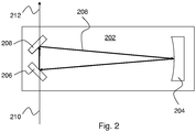
- One suitable gas detection approach is schematically shown on Fig. 2 .
- the primary gas concentration measurements are optical absorption measurements made in a resonant optical cavity disposed in an instrument in the moving platform. More specifically, Fig. 2 shows an absorption cell 202 capable of holding a gas sample for analysis.
- Absorption cell 202 includes an optical cavity defined by mirrors 204, 206, and 208. This example shows a ring cavity with a uni-directional cavity mode 208 that propagates clockwise around the cavity. Any other resonant cavity geometry can be employed.
- Cavity absorption can be measured by comparing output light 212 to input light 210. Alternatively, cavity absorption can be measured by measuring the decay rate of optical radiation emitted from the cavity (i.e., cavity ring-down spectroscopy (CRDS)).
- CRDS cavity ring-down spectroscopy
- Horizontal spatial scale analysis can be combined with the use of tracers (isotope ratio tracers and/or chemical tracers) in order to provide leak source identification. Further details relating to tracers are provided in section B below.
- Horizontal spatial scale analysis can also be combined with multi-point measurements and analysis as described in section C below.
- the resulting automatic transverse spatial scale analysis can provide a distance estimate to a leak source.
- post analysis of more sparsely sampled data can also be a viable method for correctly identifying target emissions from other background sources.
- the system can include a source of atmospheric meteorological information, especially wind direction, but also wind speed or atmospheric stability class, either on-board the platform or at a nearby stationary location.
- a source of atmospheric meteorological information especially wind direction, but also wind speed or atmospheric stability class, either on-board the platform or at a nearby stationary location.
- 'Nearby' means close enough that the atmospheric conditions at the location of the platform are well-correlated to the stationary measurements.
- the system can include an on-board video camera and logging system that can be used to reject potential sources on the basis of the local imagery collected along with the concentration data. For example, a measured emissions spike could be discounted if a vehicle powered by natural gas passed nearby during the measurements.
- the platform track should be as close to potential sources as possible. With decreasing distance to the emission source: 1) The primary concentration signal will increase, allowing for better confidence in source identification and/or more sensitive leak detection; 2) The effect of wind to hide signals or shift the measured location relative to the leak location is reduced; and 3) The spatial extent of the concentration signal from the leak becomes narrower, making it easier to distinguish from background signals and the plumes from more distant (or extended) sources, which have much more slowly varying signals.
- repeated measurements of a single location can be made to provide further confirmation (or rejection) of potential leaks.
- measurements can be made on different sides of the road or in different lanes to provide more precise localization of the leak source.
- the present approach can be used in conjunction with other conventional methods, such as visual inspection and/or measurements with handheld meters to detect emitted constituents, to further refine the results.
- measurements can be made at reduced speed, or parked at or near the source, to provide additional information on location and/or source attribution.
- This section give a specific example of horizontal spatial scale analysis in connection with methane gas leak detection.
- the methane concentration is measured initially as a function of time. It is combined with the output of the GPS receiver in order to obtain the methane concentration as a function of distance from some initial point. Interpolation can be used to sample the data on a regularly spaced collection of points.
- the concentration of methane typically varies smoothly with position, for the most part being equal to the worldwide background level of 1.8 parts per million together with enhancements from large and relatively distant sources such as landfills and marshes. These enhancements can raise the background level by several parts per million.
- a typical natural gas leak produces a plume of methane which is quite narrow in spatial extent. Although it varies with the atmospheric stability conditions, it is not until the plume has propagated more than 100 m that its half-width is of order 20 m in size.
- the value of the maximum is about 0.385 times the amplitude of the original peak in f. Away from the peak, this falls smoothly to zero.
- an additional filtering step can be applied which selects amplitudes above a certain threshold (or within a certain range).
- the remaining peaks can be displayed as leak indications, using icons whose sizes indicate the amplitude of the peak, and whose positions on a map indicate where along the path the peak was located.
- methane isotopic ratios ⁇ D of CH 4 ( ⁇ ) relative to Vienna standard mean ocean water (VSMOW), and ⁇ 13 C of CH 4 ( ⁇ ) relative to Vienna Pee Dee Belemnite (VPDB)
- VSMOW Vienna standard mean ocean water
- VPDB Vienna Pee Dee Belemnite
- these ranges are about -350 ⁇ ⁇ D ⁇ - 260 and -63 ⁇ ⁇ 13 C ⁇ -40.
- isotope ratio measurements can be used to provide source identification for methane. It is expected that isotope ratio source identification is applicable in general for leak measurements of any gas.
- a method starts with primary gas concentration measurements from a moving platform as described above (horizontal spatial scale analysis can be performed or omitted from the above-described methods).
- One or more secondary isotope ratio measurements from the moving platform are also performed from the moving platform.
- the secondary isotope ratio measurements are used to provide source identification, while the primary gas concentration measurements are used to determine presence/absence of a gas leak.
- chemical tracer analysis can be performed in addition to the isotope ratio analysis for source identification.
- natural gas tagged with mercaptans can use the mercaptans as a chemical tracer to distinguish vs. other sources of natural gas, in combination with the isotopic ratio source identification.
- methane as the primary concentration measurement
- other common sources of methane in an urban environment are sewer systems, landfills, petrochemical processing facilities, or other industrial activity.
- An example of a useful tracer for methane is the stable isotope ratio of carbon ( 13 C/ 12 C) in the methane sample.
- Natural gas is an example of a petrogenic source of methane, which has a different stable isotope ratio than the biogenic gas emitted by from the sewer system, storm drains, or landfills, for example.
- candidate tracer species include but are not limited to the hydrogen stable isotope ratio 2 H/ 1 H, hydrogen sulfide or other odorants in the natural gas; or ethane, propane, or other hydrocarbons.
- multiple tracers give additional dimensionality, allowing for even more effective methods of distinguishing target sources from other sources of the primary constituent.
- Figs. 3a -b show examples of such plots.
- the example of Fig. 3a shows a typical signal for a leak detection (y intercept differs from background level).
- the example of Fig. 3b shows a typical background signal (y intercept same as background level).
- Keeling plot analysis The basic principles of a Keeling plot analysis are as follows. For a single tracer, this ratio will vary from the background value in ambient air to a value that approaches, but does not reach, the ratio found in the pure emission, due to the fact that the observed ratio is due to a mixture of background gas and emissions.
- An analysis called a Keeling plot (developed by Charles Keeling for the analysis of carbon 13 present in atmospheric carbon dioxide) can be used to clearly identify background and source, by plotting the tracer ratio as a function of the inverse of the observed primary concentration. The intercept of this graph is the tracer ratio of the emission source. If this value can be distinguished from other possible sources, then an unambiguous source determination can be made. In this instance, 'distinguished from' means that the intercept determined from the plot does not differ from the expected source signature in a statistically significant manner. For multiple tracers, the Keeling method can be extended to multiple tracer ratios.
- Keeling methods are best applied when the tracer measurements can be made in real time.
- the Keeling method can still be applied for source determination, as long as care as taken to collect flask samples both at or near the peak, and on the baseline nearby, where the concentration levels have returned to ambient but not so far away that other sources of the primary concentration or the tracer are influencing the results.
- a gas handling system can be employed in connection with the secondary isotope ratio measurements.
- a gas handling system can be used to acquire one or more samples and to provide the acquired samples to an off-line isotope ratio measuring instrument.
- off-line indicates that the isotope ratio measurements are typically significantly slower than the primary gas concentration measurements as described above.
- the isotope ratio measurement are off-line with respect to the time scale of the primary concentration measurements.
- the isotope ratio measurement instrument is preferably disposed on the moving platform. Acquired isotope ratio samples can be analyzed on-board.
- Fig. 4 shows an example.
- a gas handling system 406 stores a sample acquired at inlet 402 in chamber 404, and is capable of providing the contents of chamber 404 to instrument 104 (here instrument 104 is an isotope ratio instrument).
- any approach for performing secondary isotope ratio measurements can be employed. If chemical tracers are measured as well, any approach for such tracer measurements can be employed. Preferably, optical absorption spectroscopy as described above is employed. Stationary measurements can be used in addition to the primary gas concentration measurements, as described above.
- Secondary isotope ratio measurements can be combined with multi-point measurements and analysis as described in section C below.
- the resulting automatic transverse spatial scale analysis can provide a distance estimate to a leak source.
- a multi-point measurement is any measurement from two or more points on the moving platform that are transversely separated from each other.
- Figs. 5a -c show example of transverse separation. Let z be the direction of platform travel, y be the vertical direction and x be perpendicular to y and z.
- Fig. 5a shows transversely separated measurement points 502 and 504 where the separation is entirely in the x direction.
- Fig. 5b shows transversely separated measurement points 502 and 504 where the separation is partly in the x direction and partly in the z direction. Points 502 and 504 on Fig.
- FIG. 5b are transversely separated because there is a non-zero separation in the x direction.
- Fig. 5c shows transversely separated measurement points 502 and 504 where the separation is entirely in the y direction.
- the measurement points are disposed on a mast 506.
- a method starts with primary gas concentration measurements from a moving platform as described above (horizontal spatial scale analysis can be performed or omitted from the above-described methods).
- the multi-point measurements are used to provide a distance estimate. More specifically, a distance between a platform measurement position and a leak source location is estimated, where the platform measurement position is the platform position at the time the relevant measurements were performed. Automatic spatial scale analysis of the multi-point measurements is used to provide this distance estimate. Results, including the distance estimate, can be provided to an end user in various ways. Preferably, the measurement points are separated from each other vertically (e.g., as in the example of Fig. 5c ).
- the spatial scale analysis can include providing a gas leak plume model and inverting this model to determine a source distance from a measured concentration gradient. Note that this measured concentration gradient can be determined from multi-point measurements as considered herein. Real-time atmospheric data can be included in the gas plume model.
- Various gas handling approaches can be employed in connection with multi-point measurements.
- the underlying requirement is to obtain simultaneous or nearly simultaneous (i.e., preferably within about 5 seconds, more preferably within about 1 second) measurements.
- Figs. 6a -c show examples of various two-point measurements. All of these approaches can be extended to measurements at any number of transversely separated points.
- the example of Fig. 6a shows two instruments 104a and 104b having separated inlets 502 and 504. This can clearly provide simultaneous measurements, but has the disadvantage of increasing cost by duplicating the measurement instrument.
- the example of Fig. 6b shows a single instrument 104 connected to inlets 502 and 504 via a switch 602. If the switch and instrument are sufficiently fast, this approach can provide nearly simultaneous measurements at the inlets.
- Fig. 6c shows a gas handling system 604 having separated inlets 502 and 504 that is capable of providing simultaneously or nearly simultaneously acquired samples to a single instrument in sequence.
- samples acquired at inlets 502 and 504 can be stored in chambers 606 and 608 respectively, and provided to instrument 104 in sequence.
- the time difference between analysis of chamber 606 and chamber 608 is not important.
- primary gas concentration measurements are performed with optical absorption spectroscopy as described above.
- Stationary gas concentration measurements as described above can also be employed.
- the dimensions of the Gaussian distribution horizontally and vertically increase with increasing distance, and the amount they increase can be estimated from measurements of wind speed, solar irradiation, ground albedo, humidity, and terrain and obstacles, all of which influence the turbulent mixing of the atmosphere.
- the turbulent mixing of the atmosphere can be estimated simply from the wind speed, the time of day, and the degree of cloudiness, all of which are parameters that are available either on the platform or from public weather databases in real time.
- estimates of the Gaussian width parameters can be estimated (e.g., by using the Pasquill-Gifford-Turner turbulence typing scheme, or modified versions of this scheme).
- the multi-point vertical measurement can be used to estimate the vertical Guassian width.
- the horizontal width can also be estimated from horizontal spatial scale analysis, but the vertical analysis has the advantage that the vertical extent of the plume is not as strongly distorted by the motion of the platforms and other nearby platforms as is the horizontal dimension, where the plume can be carried along horizontally by the motion of a platform.
- multi-point analysis can be performed, as an alternative to using a plume model.
- a measurement point at or near the road surface e.g., within 25 cm
- the Gaussian plume model breaks down, and a threshold analysis such as (delta peak height) / (average peak height) > t (where the threshold t is the order of 0.5) can unambiguously identify such sources as local (e.g., on-road).
- Fig. 7 shows an exemplary user interface relating to embodiments of the invention.
- a map display 302 has leak figures (e.g., 704, 708, 710) superposed on it.
- the leak figures include pointers (e.g., 706) that show the location of detected leaks (i.e., platform positions at which the corresponding leak concentrations were measured).
- the figure size can be scaled according to quantities such as the peak amplitude (i.e., the amount by which the peak concentration exceeds the local background), the peak concentration, or the measured spatial width of the peak.
- Numerical parameters (such as the amplitude, concentration, width, or a severity rank of the leak within some defined region, etc.) can be displayed inside the leak figures. If isotope ratio measurements are performed, they can also be shown on the display (e.g., 712).
- the leak figures can have any shape.
- the pointers on the leak figures can have any shape.
Landscapes
- Physics & Mathematics (AREA)
- Chemical & Material Sciences (AREA)
- General Physics & Mathematics (AREA)
- Health & Medical Sciences (AREA)
- Life Sciences & Earth Sciences (AREA)
- Analytical Chemistry (AREA)
- Biochemistry (AREA)
- General Health & Medical Sciences (AREA)
- Engineering & Computer Science (AREA)
- Immunology (AREA)
- Pathology (AREA)
- Spectroscopy & Molecular Physics (AREA)
- Medicinal Chemistry (AREA)
- Food Science & Technology (AREA)
- Combustion & Propulsion (AREA)
- Examining Or Testing Airtightness (AREA)
Claims (12)
- Verfahren zur Gasleckerkennung und -ortung, wobei das Verfahren Folgendes umfasst:Durchführen einer oder mehrerer Gaskonzentrationsmessungen ausgehend von einem Gasmessinstrument (104), das von einem Fahrzeug oder einer mobilen Einheit (102) transportiert wird, das/die entlang mindestens eines Bahnsteiggleises (106), das nahe eines oder mehrerer potentieller Gasleckstellen angeordnet ist, verfährt;Durchführen einer automatischen horizontalen räumlichen Skalenanalyse der Gaskonzentrationsmessungen;automatisches Bestimmen, ob an einer oder mehreren der potentiellen Gasleckstellen ein Gasleck vorhanden ist oder nicht, basierend auf der automatischen horizontalen räumlichen Skalenanalyse; undBereitstellen einer Leckanzeige an den potentiellen Gasleckstellen für einen Endnutzer;dadurch gekennzeichnet, dass die horizontale räumliche Skalenanalyse auf Halbwertsbreiten der Gaskonzentration in einem Erkennungsbereich von etwa 1 m bis etwa 50 m reagiert und im Wesentlichen nicht auf Halbwertsbreiten der Gaskonzentration außerhalb des Erkennungsbereichs reagiert,wobei f(x) die gemessene Gaskonzentration als Funktion der Position x ist, wobei g(x,w) eine Gauss-Kernfunktion ist, die eine räumliche Skala aufweist, die durch den Parameter w bestimmt ist, wobei L(x,w) eine Faltung von f(x) und g(x,w) ist und wobei Kandidatenspitzenwerte der Gaskonzentration durch die Ortung eines oder mehrerer lokaler Maxima von F(x, w)= w(δ2L(x,w)/δw2) in Bezug sowohl auf x als auch auf w identifiziert werden.
- Verfahren nach Anspruch 1, wobei F(x,w) nur über einen w-Bereich ausgerechnet wird, der dem Erkennungsbereich entspricht.
- Verfahren nach Anspruch 1, wobei die Leckanzeige durch Vergleichen der Werte von F(x,w) an ihren lokalen Maxima mit einem vorbestimmten Grenzwert erhalten wird.
- Verfahren nach Anspruch 1, wobei ein lokales Maximum F(x,w) die Koordinaten x̂ und ŵ hat und wobei sich die entsprechende Spitzenwertpositions- und -breitenschätzungen x0 bzw. w0 aus x0 = x̂ und

- Verfahren nach Anspruch 1, wobei die Gaskonzentrationsmessungen mit einer Rate von 0,2 Hz oder darüber durchgeführt werden, und weiter umfassend:Messen der Position des Fahrzeugs oder der mobilen Einheit (102) mit einer Rate von 0,2 Hz oder darüber, um die gemessenen Bahnsteigpositionen bereitzustellen; undKombinieren der gemessenen Positionen des Fahrzeugs oder der mobilen Einheit mit den Gaskonzentrationsmessungen, um Daten der Gaskonzentration gegenüber der Position für die automatische horizontale räumliche Skalenanalyse bereitzustellen.
- Verfahren nach Anspruch 1, weiter Folgendes umfassend:Durchführen einer oder mehrerer Tracermessungen ausgehend von dem Gasmessinstrument (104), das von einem Fahrzeug oder mobilen Einheit (102) transportiert wird, das/die entlang des mindestens einen Bahnsteiggleises (106), verfährt;wobei das automatische Bestimmen, ob ein Gasleck an den potentiellen Gasleckstellen vorhanden ist oder nicht, auch auf den Tracermessungen basiert.
- Verfahren nach Anspruch 6, wobei die eine oder die mehreren Tracermessungen in der Lage sind, zwischen verschiedenen Quellen des Gases, das durch die Gaskonzentrationsmessungen gemessen wurde, zu unterscheiden.
- Verfahren nach Anspruch 7, wobei die eine oder die mehreren Tracermessungen Messungen der Isotopenverhältnisse umfassen.
- Verfahren nach Anspruch 1, weiter Folgendes umfassend:Durchführen einer oder mehrerer Gaskonzentrationsmessungen an zwei oder mehreren in Querrichtung getrennten Stellen am Fahrzeug oder an der mobilen Einheit (102), während es/sie entlang des mindestens einen Bahnsteiggleises (106) verfährt;Durchführen einer automatischen transversalen räumlichen Skalenanalyse der Gaskonzentrationsmessungen;wobei das automatische Bestimmen, ob ein Gasleck an den potentiellen Gasleckstellen vorhanden ist oder nicht, auch auf der automatischen transversalen räumlichen Skalenanalyse basiert.
- Verfahren nach Anspruch 1, weiter umfassend das Bereitstellen einer Anzeige, die eine Karte mit Leckdarstellungen (704, 708, 710) zeigt, die die Karte überlagern, um erkannte Lecks zu zeigen, wobei die Leckdarstellungen (704, 708, 710) Zeiger umfassen, die die Stellen der erkannten Lecks zeigen, und wobei die Größen der Leckdarstellungen (704, 708, 710) mit einem Unterschied zwischen der gemessenen Konzentration und einer lokalen Grundbelastung skaliert sind.
- Verfahren nach Anspruch 1, weiter umfassend das Bereitstellen einer Anzeige, die eine Karte mit Leckdarstellungen (704, 708, 710) zeigt, die die Karte überlagern, um erkannte Lecks zu zeigen, wobei die Leckdarstellungen (704, 708, 710) Zeiger umfassen, die die Stellen der erkannten Lecks zeigen, und wobei die Größen der Leckdarstellungen (704, 708, 710) mit der gemessenen Konzentration skaliert sind.
- Verfahren nach Anspruch 1, weiter umfassend das Bereitstellen einer Anzeige, die eine Karte mit Leckdarstellungen (704, 708, 710) zeigt, die die Karte überlagern, um erkannte Lecks zu zeigen, wobei die Größe der Leckzahlen (704, 708, 710) mit der gemessenen räumlichen Breite des Lecks skaliert sind.
Applications Claiming Priority (2)
| Application Number | Priority Date | Filing Date | Title |
|---|---|---|---|
| US13/656,080 US9482591B2 (en) | 2011-10-20 | 2012-10-19 | Methods for gas leak detection and localization in populated areas using horizontal analysis |
| PCT/US2013/065709 WO2014063069A1 (en) | 2012-10-19 | 2013-10-18 | Methods for gas leak detection and localization in populated areas using horizontal analysis |
Publications (3)
| Publication Number | Publication Date |
|---|---|
| EP2909598A1 EP2909598A1 (de) | 2015-08-26 |
| EP2909598A4 EP2909598A4 (de) | 2016-06-22 |
| EP2909598B1 true EP2909598B1 (de) | 2018-07-04 |
Family
ID=50488947
Family Applications (1)
| Application Number | Title | Priority Date | Filing Date |
|---|---|---|---|
| EP13847836.7A Active EP2909598B1 (de) | 2012-10-19 | 2013-10-18 | Verfahren zur leckerkennung und -ortung in wohngebiete mittels horizontaler analyse |
Country Status (7)
| Country | Link |
|---|---|
| US (1) | US9482591B2 (de) |
| EP (1) | EP2909598B1 (de) |
| JP (1) | JP6326419B2 (de) |
| CN (1) | CN104736987B (de) |
| DK (1) | DK2909598T3 (de) |
| ES (1) | ES2687548T3 (de) |
| WO (1) | WO2014063069A1 (de) |
Cited By (1)
| Publication number | Priority date | Publication date | Assignee | Title |
|---|---|---|---|---|
| US20230221219A1 (en) * | 2022-01-10 | 2023-07-13 | Bridger Photonics, Inc. | Apparatuses, systems, and methods for determining gas emssion rate detection sensitivity and gas flow speed using remote gas concentration measurements |
Families Citing this family (24)
| Publication number | Priority date | Publication date | Assignee | Title |
|---|---|---|---|---|
| US9500556B2 (en) * | 2011-10-20 | 2016-11-22 | Picarro, Inc. | Methods for gas leak detection and localization in populated areas using multi-point analysis |
| US9739758B2 (en) * | 2011-10-20 | 2017-08-22 | Picarro, Inc. | Methods for gas leak detection and localization in populated areas using isotope ratio measurements |
| US10598562B2 (en) | 2014-11-21 | 2020-03-24 | Picarro Inc. | Gas detection systems and methods using measurement position uncertainty representations |
| US10386258B1 (en) * | 2015-04-30 | 2019-08-20 | Picarro Inc. | Systems and methods for detecting changes in emission rates of gas leaks in ensembles |
| CN105114821B (zh) * | 2015-10-19 | 2017-10-03 | 叶雷 | 埋地金属管线渗漏检测方法 |
| KR102407323B1 (ko) * | 2015-11-11 | 2022-06-10 | 삼성전자 주식회사 | 전자 장치 및 가스 센서의 활용 방법 |
| US10732014B2 (en) | 2016-12-20 | 2020-08-04 | Picarro, Inc. | Emission quantification using a line scan of gas concentration data |
| US10400583B1 (en) * | 2016-12-22 | 2019-09-03 | Petra Analytics, Llc | Methods and systems for spatial change indicator analysis |
| WO2018125119A1 (en) * | 2016-12-29 | 2018-07-05 | Halliburton Energy Services, Inc. | Discrete emissions detection for a site |
| KR102586462B1 (ko) * | 2017-02-17 | 2023-10-11 | 닛토덴코 가부시키가이샤 | 가스 센싱 요소 및 그 제조 방법 |
| US10948471B1 (en) | 2017-06-01 | 2021-03-16 | Picarro, Inc. | Leak detection event aggregation and ranking systems and methods |
| US10962437B1 (en) | 2017-06-27 | 2021-03-30 | Picarro, Inc. | Aggregate leak indicator display systems and methods |
| CN108535414B (zh) * | 2018-04-03 | 2020-01-10 | 北京戴纳实验科技有限公司 | 轨道式巡检系统 |
| CN109630902B (zh) * | 2018-12-07 | 2021-04-20 | 深圳市燃气集团股份有限公司 | 一种天然气管网泄露探测方法、存储介质及终端设备 |
| CN110242865B (zh) * | 2019-07-09 | 2020-05-08 | 北京讯腾智慧科技股份有限公司 | 一种易于持续优化的燃气泄漏检测判定方法及系统 |
| CN110398320B (zh) * | 2019-07-09 | 2020-11-20 | 北京讯腾智慧科技股份有限公司 | 一种易于持续优化的燃气泄漏检测定位方法及系统 |
| US11846747B2 (en) | 2019-08-23 | 2023-12-19 | Abb Schweiz Ag | Gas sampling instruments and methods |
| CA3155399A1 (en) * | 2019-11-22 | 2021-05-27 | Wenfeng Peng | Computer systems and methods for estimating changes in fugitive emissions |
| US11307137B2 (en) | 2019-11-22 | 2022-04-19 | Abb Schweiz Ag | Systems and methods for locating sources of fugitive gas emissions |
| CN111257519A (zh) * | 2020-03-18 | 2020-06-09 | 南京工业大学 | 基于传感器阵列与脉冲响应原理的建筑空间中泄漏源识别装置及方法 |
| US11761590B2 (en) | 2020-10-06 | 2023-09-19 | Abb Schweiz Ag | Technologies for producing efficient investigation routes for identifying gas leak locations |
| US11619562B2 (en) | 2020-10-06 | 2023-04-04 | Abb Schweiz Ag | Systems and methods for efficiently identifying gas leak locations |
| CN114441513B (zh) * | 2020-11-03 | 2024-02-09 | 中国石油化工股份有限公司 | 一种含硫化氢设备泄漏扩散距离的估算方法 |
| CN113551159B (zh) * | 2021-09-22 | 2021-12-03 | 天津泰达滨海清洁能源集团有限公司 | 厌氧环境下埋地燃气管道泄漏的判别方法 |
Family Cites Families (41)
| Publication number | Priority date | Publication date | Assignee | Title |
|---|---|---|---|---|
| JPS6142103Y2 (de) * | 1979-09-22 | 1986-11-29 | ||
| US4524607A (en) * | 1982-04-05 | 1985-06-25 | Science Applications International Corporation | System and method for locating leaking tubes |
| US4489239A (en) | 1982-09-24 | 1984-12-18 | The United States Of America As Represented By The Administrator Of The National Aeronautics And Space Administration | Portable remote laser sensor for methane leak detection |
| US4690689A (en) | 1983-03-02 | 1987-09-01 | Columbia Gas System Service Corp. | Gas tracer composition and method |
| US5297421A (en) | 1991-03-05 | 1994-03-29 | Mitsui Toatsu Chemicals, Inc. | Leak detection system for gas, steam or the like that involves multi-point sampling |
| JPH07280697A (ja) * | 1994-04-15 | 1995-10-27 | Tokyo Gas Co Ltd | 光反射式遠隔ガス検知装置 |
| JPH09236506A (ja) * | 1996-03-01 | 1997-09-09 | Osaka Gas Co Ltd | ガス漏れ探知装置 |
| US5946095A (en) | 1996-03-08 | 1999-08-31 | Gas Research Institute | Natural gas detection apparatus and method operable in a moving vehicle |
| AU2688999A (en) | 1998-02-20 | 1999-09-06 | Matt Emmons | Apparatus and method for the measurement of global carbon emissions from naturaland anthropogenic sources |
| GB9912332D0 (en) | 1999-05-27 | 1999-07-28 | British Gas Plc | Portable apparatus and method for tracing a gas leak |
| US6750467B2 (en) | 2002-05-14 | 2004-06-15 | John Tulip | Vehicle mounted gas detector |
| US6750453B1 (en) | 2002-05-25 | 2004-06-15 | Ophir Corporation | Methods of and apparatus for detecting low concentrations of target gases in the free atmosphere |
| RU2003103111A (ru) * | 2003-02-04 | 2004-08-20 | ООО МП Милак (RU) | Способ контроля аварийной загазованности пространства, предотвращения взрывов экстренным разгазированием, локализацией взрыва и устройство для его осуществления |
| US20040263852A1 (en) | 2003-06-03 | 2004-12-30 | Lasen, Inc. | Aerial leak detector |
| CA2476902C (en) | 2003-08-20 | 2014-04-22 | Dennis S. Prince | Innovative gas monitoring with spacial and temporal analysis |
| US6822742B1 (en) | 2003-12-19 | 2004-11-23 | Eastman Kodak Company | System and method for remote quantitative detection of fluid leaks from a natural gas or oil pipeline |
| US7704746B1 (en) | 2004-05-13 | 2010-04-27 | The United States Of America As Represented By The United States Department Of Energy | Method of detecting leakage from geologic formations used to sequester CO2 |
| US7375814B2 (en) | 2005-03-11 | 2008-05-20 | Sandia Corporation | Natural gas leak mapper |
| US7075653B1 (en) | 2005-04-29 | 2006-07-11 | Heath Consultants Incorporated | Method and apparatus for laser-based remote methane leak detection |
| CN1696629A (zh) * | 2005-06-20 | 2005-11-16 | 江苏工业学院 | 一种油气管道泄漏监测方法及其装置 |
| US7260507B2 (en) | 2005-09-09 | 2007-08-21 | Itt Manufacturing Enterprises, Inc. | Method for improving the performance accuracy in differential absorption lidar for oil and gas pipeline leak detection and quantification |
| WO2008001105A1 (en) | 2006-06-30 | 2008-01-03 | Bae Systems Plc | Sensor system for estimating varying field |
| CN1936413A (zh) * | 2006-09-29 | 2007-03-28 | 淄博思科光电科技有限公司 | 一种地下管线泄漏检测方法及其装置 |
| US20080168826A1 (en) | 2007-01-17 | 2008-07-17 | Motorola, Inc. | Method and system for gas leak detection and localization |
| JP5252533B2 (ja) * | 2007-08-08 | 2013-07-31 | 四国電力株式会社 | 車載型漏洩ガス検知システムおよび方法 |
| US7710568B1 (en) | 2007-09-28 | 2010-05-04 | Southwest Sciences Incorporated | Portable natural gas leak detector |
| CN101178153A (zh) * | 2007-12-07 | 2008-05-14 | 中国科学技术大学 | 新型城市天然气管道泄漏检测定位方法及系统 |
| US8390813B2 (en) | 2008-05-02 | 2013-03-05 | Los Alamos National Security, Llc | Apparatus and method for monitoring of gas having stable isotopes |
| CA2728631C (en) * | 2008-06-25 | 2017-07-04 | Shell Internationale Research Maatschappij B.V. | Method and system for screening an area of the atmosphere for sources of emissions |
| US8781755B2 (en) | 2008-10-08 | 2014-07-15 | Golder Associates Ltd. | Fugitive emission flux measurement |
| JP5448045B2 (ja) * | 2009-04-01 | 2014-03-19 | 独立行政法人海上技術安全研究所 | 漏洩co2検出方法及び漏洩co2検出装置、地中貯留co2の漏洩モニタリング方法 |
| CN101561081B (zh) * | 2009-05-18 | 2012-08-22 | 中国地质大学(武汉) | 应用自主导航机器人对油气管道泄漏的检测定位方法 |
| GB0916000D0 (en) | 2009-09-11 | 2009-10-28 | Selex Sensors & Airborne Sys | Sensing network and method |
| CA2681681A1 (en) | 2009-10-06 | 2010-06-08 | Colin Irvin Wong | Mapping concentrations of airborne matter |
| US9056366B2 (en) * | 2010-05-21 | 2015-06-16 | Illinois Tool Works Inc. | Welding gas leak detection system and method |
| IT1401884B1 (it) | 2010-10-06 | 2013-08-28 | Tea Sistemi S P A | Metodo per quantificare un flusso di gas fuggitivo mediante misure verticali di concentrazione |
| US9435782B2 (en) | 2011-01-20 | 2016-09-06 | Trimble Navigation Limited | Landfill gas surface monitor and methods |
| EP2503323A3 (de) | 2011-03-23 | 2012-12-19 | Helmholtz-Zentrum Potsdam Deutsches GeoForschungsZentrum - GFZ | Vorrichtung und Verfahren zur Messung der räumlichen Verteilung von atmosphärischen Gasen in Bodennähe |
| US9618417B2 (en) * | 2011-10-20 | 2017-04-11 | Picarro, Inc. | Methods for gas leak detection and localization in populated areas using isotope ratio measurements |
| US9739758B2 (en) * | 2011-10-20 | 2017-08-22 | Picarro, Inc. | Methods for gas leak detection and localization in populated areas using isotope ratio measurements |
| US9500556B2 (en) * | 2011-10-20 | 2016-11-22 | Picarro, Inc. | Methods for gas leak detection and localization in populated areas using multi-point analysis |
-
2012
- 2012-10-19 US US13/656,080 patent/US9482591B2/en active Active
-
2013
- 2013-10-18 WO PCT/US2013/065709 patent/WO2014063069A1/en not_active Ceased
- 2013-10-18 CN CN201380054787.3A patent/CN104736987B/zh active Active
- 2013-10-18 JP JP2015538062A patent/JP6326419B2/ja active Active
- 2013-10-18 ES ES13847836.7T patent/ES2687548T3/es active Active
- 2013-10-18 EP EP13847836.7A patent/EP2909598B1/de active Active
- 2013-10-18 DK DK13847836.7T patent/DK2909598T3/en active
Non-Patent Citations (1)
| Title |
|---|
| None * |
Cited By (2)
| Publication number | Priority date | Publication date | Assignee | Title |
|---|---|---|---|---|
| US20230221219A1 (en) * | 2022-01-10 | 2023-07-13 | Bridger Photonics, Inc. | Apparatuses, systems, and methods for determining gas emssion rate detection sensitivity and gas flow speed using remote gas concentration measurements |
| US12372439B2 (en) * | 2022-01-10 | 2025-07-29 | Bridger Photonics, Inc. | Apparatuses, systems, and methods for determining gas emission rate detection sensitivity and gas flow speed using remote gas concentration measurements |
Also Published As
| Publication number | Publication date |
|---|---|
| DK2909598T3 (en) | 2018-10-08 |
| WO2014063069A1 (en) | 2014-04-24 |
| US20140032160A1 (en) | 2014-01-30 |
| JP6326419B2 (ja) | 2018-05-16 |
| CN104736987B (zh) | 2019-04-16 |
| US9482591B2 (en) | 2016-11-01 |
| EP2909598A4 (de) | 2016-06-22 |
| ES2687548T3 (es) | 2018-10-25 |
| JP2015532436A (ja) | 2015-11-09 |
| CN104736987A (zh) | 2015-06-24 |
| EP2909598A1 (de) | 2015-08-26 |
Similar Documents
| Publication | Publication Date | Title |
|---|---|---|
| EP2909598B1 (de) | Verfahren zur leckerkennung und -ortung in wohngebiete mittels horizontaler analyse | |
| US11561149B2 (en) | Methods for gas leak detection and localization in populated areas having a distance estimate | |
| US9500556B2 (en) | Methods for gas leak detection and localization in populated areas using multi-point analysis | |
| US10113997B2 (en) | Methods for gas leak detection and localization in populated areas using two or more tracer measurements | |
| US9739758B2 (en) | Methods for gas leak detection and localization in populated areas using isotope ratio measurements | |
| US11525819B1 (en) | Leak detection event aggregation and ranking systems and methods | |
| US10732014B2 (en) | Emission quantification using a line scan of gas concentration data | |
| US12188861B2 (en) | Methane peak detection | |
| US20200355573A1 (en) | Emission quantification using a line scan of gas concentration data |
Legal Events
| Date | Code | Title | Description |
|---|---|---|---|
| PUAI | Public reference made under article 153(3) epc to a published international application that has entered the european phase |
Free format text: ORIGINAL CODE: 0009012 |
|
| 17P | Request for examination filed |
Effective date: 20150519 |
|
| AK | Designated contracting states |
Kind code of ref document: A1 Designated state(s): AL AT BE BG CH CY CZ DE DK EE ES FI FR GB GR HR HU IE IS IT LI LT LU LV MC MK MT NL NO PL PT RO RS SE SI SK SM TR |
|
| AX | Request for extension of the european patent |
Extension state: BA ME |
|
| DAX | Request for extension of the european patent (deleted) | ||
| RA4 | Supplementary search report drawn up and despatched (corrected) |
Effective date: 20160524 |
|
| RIC1 | Information provided on ipc code assigned before grant |
Ipc: F17D 5/02 20060101ALI20160518BHEP Ipc: G01M 3/04 20060101AFI20160518BHEP Ipc: G01N 33/00 20060101ALI20160518BHEP Ipc: G01N 21/3504 20140101ALI20160518BHEP Ipc: G01M 3/20 20060101ALI20160518BHEP Ipc: G06F 17/18 20060101ALI20160518BHEP |
|
| STAA | Information on the status of an ep patent application or granted ep patent |
Free format text: STATUS: EXAMINATION IS IN PROGRESS |
|
| 17Q | First examination report despatched |
Effective date: 20170620 |
|
| GRAP | Despatch of communication of intention to grant a patent |
Free format text: ORIGINAL CODE: EPIDOSNIGR1 |
|
| STAA | Information on the status of an ep patent application or granted ep patent |
Free format text: STATUS: GRANT OF PATENT IS INTENDED |
|
| INTG | Intention to grant announced |
Effective date: 20180316 |
|
| GRAS | Grant fee paid |
Free format text: ORIGINAL CODE: EPIDOSNIGR3 |
|
| GRAA | (expected) grant |
Free format text: ORIGINAL CODE: 0009210 |
|
| STAA | Information on the status of an ep patent application or granted ep patent |
Free format text: STATUS: THE PATENT HAS BEEN GRANTED |
|
| AK | Designated contracting states |
Kind code of ref document: B1 Designated state(s): AL AT BE BG CH CY CZ DE DK EE ES FI FR GB GR HR HU IE IS IT LI LT LU LV MC MK MT NL NO PL PT RO RS SE SI SK SM TR |
|
| REG | Reference to a national code |
Ref country code: GB Ref legal event code: FG4D |
|
| REG | Reference to a national code |
Ref country code: CH Ref legal event code: EP Ref country code: CH Ref legal event code: NV Representative=s name: STOLMAR AND PARTNER INTELLECTUAL PROPERTY S.A., CH |
|
| REG | Reference to a national code |
Ref country code: AT Ref legal event code: REF Ref document number: 1015027 Country of ref document: AT Kind code of ref document: T Effective date: 20180715 |
|
| REG | Reference to a national code |
Ref country code: IE Ref legal event code: FG4D |
|
| REG | Reference to a national code |
Ref country code: DE Ref legal event code: R096 Ref document number: 602013039863 Country of ref document: DE |
|
| REG | Reference to a national code |
Ref country code: NL Ref legal event code: FP |
|
| REG | Reference to a national code |
Ref country code: DK Ref legal event code: T3 Effective date: 20181001 |
|
| REG | Reference to a national code |
Ref country code: FR Ref legal event code: PLFP Year of fee payment: 6 |
|
| REG | Reference to a national code |
Ref country code: ES Ref legal event code: FG2A Ref document number: 2687548 Country of ref document: ES Kind code of ref document: T3 Effective date: 20181025 |
|
| REG | Reference to a national code |
Ref country code: LT Ref legal event code: MG4D |
|
| PG25 | Lapsed in a contracting state [announced via postgrant information from national office to epo] |
Ref country code: LT Free format text: LAPSE BECAUSE OF FAILURE TO SUBMIT A TRANSLATION OF THE DESCRIPTION OR TO PAY THE FEE WITHIN THE PRESCRIBED TIME-LIMIT Effective date: 20180704 Ref country code: SE Free format text: LAPSE BECAUSE OF FAILURE TO SUBMIT A TRANSLATION OF THE DESCRIPTION OR TO PAY THE FEE WITHIN THE PRESCRIBED TIME-LIMIT Effective date: 20180704 Ref country code: GR Free format text: LAPSE BECAUSE OF FAILURE TO SUBMIT A TRANSLATION OF THE DESCRIPTION OR TO PAY THE FEE WITHIN THE PRESCRIBED TIME-LIMIT Effective date: 20181005 Ref country code: FI Free format text: LAPSE BECAUSE OF FAILURE TO SUBMIT A TRANSLATION OF THE DESCRIPTION OR TO PAY THE FEE WITHIN THE PRESCRIBED TIME-LIMIT Effective date: 20180704 Ref country code: IS Free format text: LAPSE BECAUSE OF FAILURE TO SUBMIT A TRANSLATION OF THE DESCRIPTION OR TO PAY THE FEE WITHIN THE PRESCRIBED TIME-LIMIT Effective date: 20181104 Ref country code: RS Free format text: LAPSE BECAUSE OF FAILURE TO SUBMIT A TRANSLATION OF THE DESCRIPTION OR TO PAY THE FEE WITHIN THE PRESCRIBED TIME-LIMIT Effective date: 20180704 Ref country code: NO Free format text: LAPSE BECAUSE OF FAILURE TO SUBMIT A TRANSLATION OF THE DESCRIPTION OR TO PAY THE FEE WITHIN THE PRESCRIBED TIME-LIMIT Effective date: 20181004 Ref country code: CZ Free format text: LAPSE BECAUSE OF FAILURE TO SUBMIT A TRANSLATION OF THE DESCRIPTION OR TO PAY THE FEE WITHIN THE PRESCRIBED TIME-LIMIT Effective date: 20180704 Ref country code: BG Free format text: LAPSE BECAUSE OF FAILURE TO SUBMIT A TRANSLATION OF THE DESCRIPTION OR TO PAY THE FEE WITHIN THE PRESCRIBED TIME-LIMIT Effective date: 20181004 Ref country code: PL Free format text: LAPSE BECAUSE OF FAILURE TO SUBMIT A TRANSLATION OF THE DESCRIPTION OR TO PAY THE FEE WITHIN THE PRESCRIBED TIME-LIMIT Effective date: 20180704 |
|
| PG25 | Lapsed in a contracting state [announced via postgrant information from national office to epo] |
Ref country code: HR Free format text: LAPSE BECAUSE OF FAILURE TO SUBMIT A TRANSLATION OF THE DESCRIPTION OR TO PAY THE FEE WITHIN THE PRESCRIBED TIME-LIMIT Effective date: 20180704 Ref country code: LV Free format text: LAPSE BECAUSE OF FAILURE TO SUBMIT A TRANSLATION OF THE DESCRIPTION OR TO PAY THE FEE WITHIN THE PRESCRIBED TIME-LIMIT Effective date: 20180704 Ref country code: AL Free format text: LAPSE BECAUSE OF FAILURE TO SUBMIT A TRANSLATION OF THE DESCRIPTION OR TO PAY THE FEE WITHIN THE PRESCRIBED TIME-LIMIT Effective date: 20180704 |
|
| REG | Reference to a national code |
Ref country code: DE Ref legal event code: R097 Ref document number: 602013039863 Country of ref document: DE |
|
| PG25 | Lapsed in a contracting state [announced via postgrant information from national office to epo] |
Ref country code: RO Free format text: LAPSE BECAUSE OF FAILURE TO SUBMIT A TRANSLATION OF THE DESCRIPTION OR TO PAY THE FEE WITHIN THE PRESCRIBED TIME-LIMIT Effective date: 20180704 Ref country code: EE Free format text: LAPSE BECAUSE OF FAILURE TO SUBMIT A TRANSLATION OF THE DESCRIPTION OR TO PAY THE FEE WITHIN THE PRESCRIBED TIME-LIMIT Effective date: 20180704 |
|
| PLBE | No opposition filed within time limit |
Free format text: ORIGINAL CODE: 0009261 |
|
| STAA | Information on the status of an ep patent application or granted ep patent |
Free format text: STATUS: NO OPPOSITION FILED WITHIN TIME LIMIT |
|
| PG25 | Lapsed in a contracting state [announced via postgrant information from national office to epo] |
Ref country code: SM Free format text: LAPSE BECAUSE OF FAILURE TO SUBMIT A TRANSLATION OF THE DESCRIPTION OR TO PAY THE FEE WITHIN THE PRESCRIBED TIME-LIMIT Effective date: 20180704 Ref country code: SK Free format text: LAPSE BECAUSE OF FAILURE TO SUBMIT A TRANSLATION OF THE DESCRIPTION OR TO PAY THE FEE WITHIN THE PRESCRIBED TIME-LIMIT Effective date: 20180704 |
|
| 26N | No opposition filed |
Effective date: 20190405 |
|
| PG25 | Lapsed in a contracting state [announced via postgrant information from national office to epo] |
Ref country code: MC Free format text: LAPSE BECAUSE OF FAILURE TO SUBMIT A TRANSLATION OF THE DESCRIPTION OR TO PAY THE FEE WITHIN THE PRESCRIBED TIME-LIMIT Effective date: 20180704 Ref country code: LU Free format text: LAPSE BECAUSE OF NON-PAYMENT OF DUE FEES Effective date: 20181018 |
|
| REG | Reference to a national code |
Ref country code: IE Ref legal event code: MM4A |
|
| PG25 | Lapsed in a contracting state [announced via postgrant information from national office to epo] |
Ref country code: SI Free format text: LAPSE BECAUSE OF FAILURE TO SUBMIT A TRANSLATION OF THE DESCRIPTION OR TO PAY THE FEE WITHIN THE PRESCRIBED TIME-LIMIT Effective date: 20180704 |
|
| PG25 | Lapsed in a contracting state [announced via postgrant information from national office to epo] |
Ref country code: IE Free format text: LAPSE BECAUSE OF NON-PAYMENT OF DUE FEES Effective date: 20181018 |
|
| PG25 | Lapsed in a contracting state [announced via postgrant information from national office to epo] |
Ref country code: MT Free format text: LAPSE BECAUSE OF NON-PAYMENT OF DUE FEES Effective date: 20181018 |
|
| PG25 | Lapsed in a contracting state [announced via postgrant information from national office to epo] |
Ref country code: TR Free format text: LAPSE BECAUSE OF FAILURE TO SUBMIT A TRANSLATION OF THE DESCRIPTION OR TO PAY THE FEE WITHIN THE PRESCRIBED TIME-LIMIT Effective date: 20180704 |
|
| PG25 | Lapsed in a contracting state [announced via postgrant information from national office to epo] |
Ref country code: PT Free format text: LAPSE BECAUSE OF FAILURE TO SUBMIT A TRANSLATION OF THE DESCRIPTION OR TO PAY THE FEE WITHIN THE PRESCRIBED TIME-LIMIT Effective date: 20180704 |
|
| PG25 | Lapsed in a contracting state [announced via postgrant information from national office to epo] |
Ref country code: CY Free format text: LAPSE BECAUSE OF FAILURE TO SUBMIT A TRANSLATION OF THE DESCRIPTION OR TO PAY THE FEE WITHIN THE PRESCRIBED TIME-LIMIT Effective date: 20180704 Ref country code: MK Free format text: LAPSE BECAUSE OF NON-PAYMENT OF DUE FEES Effective date: 20180704 Ref country code: HU Free format text: LAPSE BECAUSE OF FAILURE TO SUBMIT A TRANSLATION OF THE DESCRIPTION OR TO PAY THE FEE WITHIN THE PRESCRIBED TIME-LIMIT; INVALID AB INITIO Effective date: 20131018 |
|
| REG | Reference to a national code |
Ref country code: AT Ref legal event code: UEP Ref document number: 1015027 Country of ref document: AT Kind code of ref document: T Effective date: 20180704 |
|
| PGFP | Annual fee paid to national office [announced via postgrant information from national office to epo] |
Ref country code: NL Payment date: 20241021 Year of fee payment: 12 |
|
| PGFP | Annual fee paid to national office [announced via postgrant information from national office to epo] |
Ref country code: DK Payment date: 20241021 Year of fee payment: 12 |
|
| PGFP | Annual fee paid to national office [announced via postgrant information from national office to epo] |
Ref country code: BE Payment date: 20241021 Year of fee payment: 12 |
|
| PGFP | Annual fee paid to national office [announced via postgrant information from national office to epo] |
Ref country code: GB Payment date: 20241021 Year of fee payment: 12 |
|
| PGFP | Annual fee paid to national office [announced via postgrant information from national office to epo] |
Ref country code: FR Payment date: 20241030 Year of fee payment: 12 |
|
| PGFP | Annual fee paid to national office [announced via postgrant information from national office to epo] |
Ref country code: IT Payment date: 20241025 Year of fee payment: 12 Ref country code: ES Payment date: 20241104 Year of fee payment: 12 |
|
| PGFP | Annual fee paid to national office [announced via postgrant information from national office to epo] |
Ref country code: CH Payment date: 20241101 Year of fee payment: 12 |
|
| PGFP | Annual fee paid to national office [announced via postgrant information from national office to epo] |
Ref country code: DE Payment date: 20250423 Year of fee payment: 12 |
|
| REG | Reference to a national code |
Ref country code: CH Ref legal event code: U11 Free format text: ST27 STATUS EVENT CODE: U-0-0-U10-U11 (AS PROVIDED BY THE NATIONAL OFFICE) Effective date: 20260413 |
|
| PGFP | Annual fee paid to national office [announced via postgrant information from national office to epo] |
Ref country code: AT Payment date: 20260410 Year of fee payment: 13 |