EP2910202B1 - Instrument destiné à exécuter des interventions médicales - Google Patents
Instrument destiné à exécuter des interventions médicales Download PDFInfo
- Publication number
- EP2910202B1 EP2910202B1 EP15152582.1A EP15152582A EP2910202B1 EP 2910202 B1 EP2910202 B1 EP 2910202B1 EP 15152582 A EP15152582 A EP 15152582A EP 2910202 B1 EP2910202 B1 EP 2910202B1
- Authority
- EP
- European Patent Office
- Prior art keywords
- wheel
- instrument head
- instrument
- drive
- head
- Prior art date
- Legal status (The legal status is an assumption and is not a legal conclusion. Google has not performed a legal analysis and makes no representation as to the accuracy of the status listed.)
- Active
Links
Images

Classifications
-
- A—HUMAN NECESSITIES
- A61—MEDICAL OR VETERINARY SCIENCE; HYGIENE
- A61B—DIAGNOSIS; SURGERY; IDENTIFICATION
- A61B17/00—Surgical instruments, devices or methods
- A61B17/28—Surgical forceps
- A61B17/29—Forceps for use in minimally invasive surgery
-
- A—HUMAN NECESSITIES
- A61—MEDICAL OR VETERINARY SCIENCE; HYGIENE
- A61B—DIAGNOSIS; SURGERY; IDENTIFICATION
- A61B17/00—Surgical instruments, devices or methods
- A61B17/00234—Surgical instruments, devices or methods for minimally invasive surgery
-
- A—HUMAN NECESSITIES
- A61—MEDICAL OR VETERINARY SCIENCE; HYGIENE
- A61B—DIAGNOSIS; SURGERY; IDENTIFICATION
- A61B17/00—Surgical instruments, devices or methods
- A61B17/28—Surgical forceps
- A61B17/2812—Surgical forceps with a single pivotal connection
- A61B17/2816—Pivots
-
- A—HUMAN NECESSITIES
- A61—MEDICAL OR VETERINARY SCIENCE; HYGIENE
- A61B—DIAGNOSIS; SURGERY; IDENTIFICATION
- A61B17/00—Surgical instruments, devices or methods
- A61B17/28—Surgical forceps
- A61B17/29—Forceps for use in minimally invasive surgery
- A61B2017/2926—Details of heads or jaws
- A61B2017/2927—Details of heads or jaws the angular position of the head being adjustable with respect to the shaft
-
- A—HUMAN NECESSITIES
- A61—MEDICAL OR VETERINARY SCIENCE; HYGIENE
- A61B—DIAGNOSIS; SURGERY; IDENTIFICATION
- A61B17/00—Surgical instruments, devices or methods
- A61B17/28—Surgical forceps
- A61B17/29—Forceps for use in minimally invasive surgery
- A61B2017/2926—Details of heads or jaws
- A61B2017/2927—Details of heads or jaws the angular position of the head being adjustable with respect to the shaft
- A61B2017/2929—Details of heads or jaws the angular position of the head being adjustable with respect to the shaft with a head rotatable about the longitudinal axis of the shaft
-
- A—HUMAN NECESSITIES
- A61—MEDICAL OR VETERINARY SCIENCE; HYGIENE
- A61B—DIAGNOSIS; SURGERY; IDENTIFICATION
- A61B17/00—Surgical instruments, devices or methods
- A61B17/28—Surgical forceps
- A61B17/29—Forceps for use in minimally invasive surgery
- A61B2017/2926—Details of heads or jaws
- A61B2017/2932—Transmission of forces to jaw members
- A61B2017/2939—Details of linkages or pivot points
-
- A—HUMAN NECESSITIES
- A61—MEDICAL OR VETERINARY SCIENCE; HYGIENE
- A61B—DIAGNOSIS; SURGERY; IDENTIFICATION
- A61B17/00—Surgical instruments, devices or methods
- A61B17/28—Surgical forceps
- A61B17/29—Forceps for use in minimally invasive surgery
- A61B2017/2926—Details of heads or jaws
- A61B2017/2932—Transmission of forces to jaw members
- A61B2017/2939—Details of linkages or pivot points
- A61B2017/294—Connection of actuating rod to jaw, e.g. releasable
-
- A—HUMAN NECESSITIES
- A61—MEDICAL OR VETERINARY SCIENCE; HYGIENE
- A61B—DIAGNOSIS; SURGERY; IDENTIFICATION
- A61B17/00—Surgical instruments, devices or methods
- A61B17/28—Surgical forceps
- A61B17/29—Forceps for use in minimally invasive surgery
- A61B2017/2947—Pivots
-
- A—HUMAN NECESSITIES
- A61—MEDICAL OR VETERINARY SCIENCE; HYGIENE
- A61B—DIAGNOSIS; SURGERY; IDENTIFICATION
- A61B17/00—Surgical instruments, devices or methods
- A61B17/32—Surgical cutting instruments
- A61B2017/320044—Blunt dissectors
Definitions
- the present invention relates to an instrument for performing medical procedures comprising a tubular shaft elongated along a shaft longitudinal axis, an instrument head, the instrument head being pivotally supported on the tubular shaft about an instrument head pivot axis and at least a portion of the instrument head being rotatable about an instrument head longitudinal axis, and a Wheel gear assembly for moving the instrument head, wherein at least a part of the instrument head is driven by the Radgetriebean Aunt for rotation about the instrument head longitudinal axis.
- Such instruments also referred to as tubular shaft instruments, are used, for example, in the context of endoscopic, minimally invasive surgical procedures in order to manipulate or separate tissue.
- an instrument constructed with a tubular shaft in which an instrument head is pivotally connected to the tubular shaft in the distal end region thereof.
- a portion of the instrument head is rotatable about an axis of rotation substantially orthogonal to the axis of the pivotal connection of the instrument head to the tubular shaft.
- a bevel gear arrangement designed as a bevel gear arrangement, which comprises a shaft extending in the drive shaft with a rotatably supported drive bevel gear, a rotatable with the rotatable part of the instrument head output shaft bevel gear and meshing with these êtskegelrad.
- the part of the instrument head which in particular carries the tools for a surgical procedure can be set in rotation.
- a push tube is arranged in the tubular shaft, which is coupled via a hinge connection with the part of the instrument head articulated on the tubular shaft is.
- an actuating force is exerted on the instrument head, so that it pivots about a pivot axis with respect to the tubular shaft.
- an instrument for carrying out medical procedures comprising a tube shaft elongated along a shaft longitudinal axis, an instrument head, the instrument head being pivotally supported on the tube shaft about an instrument head pivot axis and at least a portion of the instrument head being rotatable about an instrument head longitudinal axis, and a Wheel gear assembly for moving the instrument head, wherein at least a part of the instrument head is driven by the Radgetriebean Aunt for rotation about the instrument head longitudinal axis.
- instrument head can be driven by the wheel gear assembly for pivoting about the instrument head pivot axis.
- the instrument head is driven both for pivoting and for rotation through the wheel gear arrangement, so that additional mechanisms, such. As a push rod, are not required for generating the pivoting movement.
- the wheel gear arrangement comprise a first wheel train with a first drive wheel, a first transmission wheel and a first output wheel, and a second wheel train with a second drive wheel, a second transmission wheel and a second output gear. It is then advantageously provided that the first transmission wheel is in transmission interaction with the first drive wheel and the first output gear, while the second transmission wheel is in transference interaction with the second drive wheel and the second output gear.
- the wheel gear arrangement comprises two wheel gear trains which are basically constructed independently of each other but cooperate to produce the various states of motion.
- the first output gear and the second driven gear are arranged concentrically to the instrument head longitudinal axis and / or rotationally fixed to the part of the instrument head rotatable about the instrument head longitudinal axis.
- the interaction of the two Radgetriebeans notion provide that the first drive wheel and the second drive wheel to the shaft longitudinal axis are arranged concentrically and rotatable about the shaft longitudinal axis.
- a very compact design can be achieved in that the first drive wheel is non-rotatable on a first drive shaft, that the second drive wheel is non-rotatable on a second drive shaft and that the first drive shaft is formed as the second drive shaft receiving hollow shaft.
- the first transmission wheel and the second transmission wheel may be arranged to be rotatable about a common transmission wheel rotation axis, which may advantageously correspond to the instrument head pivot axis. This ensures that regardless of the pivot position of the instrument head, the drive-side wheels and the driven-side wheels can always interact evenly with the transmission wheels.
- the two above-mentioned states of motion, ie rotation and pivoting of the instrument head or at least a part thereof by the cooperating, but basically independently driven Radgetriebescope can be achieved in a particularly simple and advantageous manner, if the first transmission wheel and the second transmission wheel with respect to the instrument head longitudinal axis or / and the shaft longitudinal axis are arranged opposite to each other. In particular, this positioning also enables the parallel action of the two transmission wheels on the instrument head for generating a pivoting torque acting on the instrument head.
- a particularly simple operation of the two Radgetriebetician to cooperate the same to generate the two states of motion can be achieved in that the first Radgetriebeddling and the second Radgetriebezug the same Wheeliereumsetzson, preferably 1: 1, have.
- This makes it possible to drive the two drive wheels in the same direction or in opposite directions at the same speed, but at the same time also to achieve the same speed on both sides of the gearbox on the output side.
- the wheel gear arrangement is a bevel gear arrangement with a first bevel gear train and a second bevel gear train, wherein the first bevel gear train is a first drive bevel gear, a first pinion gear and a first output pinion gear and the second bevel gear train comprises a second pinion gear, a second pinion gear and a second output pinion.
- a jaw part can be pivotally supported on the instrument head about a jaw part pivot axis.
- a preferably flexible pivoting actuating linkage extending through the instrument head and the tubular shaft can be provided. Due to the flexibility of the pivoting actuating linkage, the pivoting operation is ensured independently of the pivotal positioning of the instrument head with respect to the tubular shaft.
- the second drive shaft is designed as a hollow actuating shaft receiving the pivoting actuating linkage.
- mutual interference with the instrument head pivoting on the instrument shaft to the instrument shaft can be avoided by having a passage opening for the actuation rod.
- a drive arrangement for driving the instrument head for pivotal movement about the instrument head pivot axis and for rotational movement about the instrument head longitudinal axis.
- This drive arrangement may in principle comprise one or more manually operated actuators, but may also be motorized with one or more of the drive-side bevel gears or the shafts carrying these driving motors.
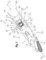
- the Fig. 1 and 2 show an instrument that can be used to perform endoscopic, minimally invasive medical procedures, for example, to manipulate or remove tissue.
- the instrument generally designated 10 comprises an elongate tubular shaft 12 which may be formed in one or more parts and is connected in its distal end portion 14 in a hinge connection portion 16 with an instrument head 18.
- the instrument head 18 in its entirety forms the distal end region 20 of the instrument 10.
- the instrument head 18 is constructed in several parts with a first head part 22 which is connected in an articulated manner to the tubular shaft 12 in the manner described below in the joint connection region 16.
- a second head part 24 adjoining the first head part 22 is pivotable together with the first head part 22 about an instrument head pivot axis S K with respect to the tubular shaft 12 and is rotatable about an instrument head longitudinal axis L K with respect to the tubular shaft 12 or also with respect to the first head part 22.
- a jaw part 26 is pivotally supported about a jaw part pivot axis S M. By pivoting the jaw part 26, this can be moved to remove or release, for example, a tissue sample with respect to the second head part 24.
- This swiveling movement of the jaw part 26 can be brought about by a swivel actuation linkage 28, which is articulated to the jaw part 26, for example, and extends through the instrument 10, that is to say the head part 18 and the tubular shaft 12.
- the tubular shaft 12 or a section formed as a distal end part 30 of the same has two joint plates 32, 34 which are transverse to a shaft longitudinal axis L s , z. B. longitudinal center axis, are arranged at a distance from each other.
- the instrument head 18 and the first head part 22 thereof has correspondingly two joint plates 36, 38 which are transverse to a longitudinal axis of the instrument head L K , z. B. longitudinal center axis, are arranged at a distance to each other, however, such that they lie within the two hinge plates 32, 34 of the tubular shaft 12.
- An instrument head pivot pin 40 passes through openings provided in the hinge tabs 32, 34, 36, 38 and aligned with each other.
- the instrument head pivot pin 40 may be secured to either at least one of the hinge tabs 32, 34 or at least one of the hinge tabs 36, 38 to prevent the instrument head pivot pin 40 from moving out of the receiving apertures.
- the component which is not firmly connected to the instrument head pivot pin 40 with any of its joint plates, can perform a pivoting or rotational movement on the instrument head pivot pin 40 fixed relative to the other component.
- the instrument head pivot pin 40 does not necessarily have to protrude laterally beyond the externally disposed hinge tabs 32, 34 to the extent shown.
- the instrument head pivot pin 40 advantageously terminates substantially flush with the outer surface of, for example, the tubular shaft 12, or does not protrude beyond it out.
- the instrument 10 has a wheel gear arrangement designed as a bevel gear arrangement 42.
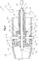
- This bevel gear assembly 42 for generating the two above-mentioned movements will be described below with reference to Fig. 3 described in detail.
- the bevel gear arrangement 42 comprises two bevel gear trains 44, 46 cooperating to produce the two above-mentioned states of motion.
- the first bevel gear train 44 comprises a first drive bevel gear 50 provided on a first drive shaft 48.
- the first drive shaft 48 advantageously extends coaxially with the shaft longitudinal axis L s in the tube shaft 12 and ends in the articulation region 16 advantageously such that the provided thereon first drive bevel gear 50 is disposed in the released by the joint plates 32, 34, 36, 38 space area.
- the shaft longitudinal axis L s can essentially be defined by an axis of rotation of the first drive shaft 48 or the first drive bevel gear 50 or also corresponding assemblies of the second bevel gear train 46 explained below.
- an axis of rotation coincides with a longitudinal center axis of the tubular shaft 12.
- the first bevel gear train 44 further includes a first output bevel gear 52. This is rotatably connected to the second head part 24 and arranged centric to the instrument head longitudinal axis L ⁇ .
- a first transfer bevel gear 54 of the first bevel gear train 44 is provided for torque transmission between the first drive bevel gear 50 and the first driven bevel gear 52.
- the first transfer bevel gear 54 is rotatably supported on the instrument head pivot pin 40 and secured against displacement on the instrument head pivot pin 40, for example, by being supported on the hinge tab 36 on the one hand and on the two bevel gears 50, 52 on the other hand.
- measures could also be provided directly on the instrument head pivot pin 40, for example by steps or retaining rings or the like, which prevent a displacement of the first transmission bevel gear 54 along the instrument head pivot pin 40.
- the second bevel gear train 46 comprises a second drive shaft 56 extending in the tubular shaft 12.
- the second drive shaft 56 extends within the first drive shaft 48 designed as a hollow shaft and is advantageously arranged therewith substantially concentrically with the shaft longitudinal axis L s .
- the second drive shaft 56 In its end region beyond the first drive shaft 48, the second drive shaft 56 has a second drive bevel gear 58 so that it is rotationally fixed.
- a second output bevel gear 60 which is arranged centrically to the instrument head longitudinal axis L K, is provided in association with the second drive bevel gear 58. This is thus arranged concentrically with the first output bevel gear 52 to the instrument head longitudinal axis L K and is also firmly connected to the first output bevel gear 52 and the second head part 24 for common rotation about the instrument head longitudinal axis L K.
- This fixed connection can be achieved on the one hand by designing the two driven bevel gears 52, 60 and the second head part 24 as separate components and the subsequent firm connection thereof. Alternatively, at least two of these components could be made integral with each other.
- the two output bevel gears 52, 60 could be provided by different cone sections of a common output bevel gear.
- the second bevel gear train 46 further includes a second transfer bevel gear 62. This is rotatably supported on the instrument head pivot pin 40.
- the second transfer bevel gear 62 transmits torque between the second drive bevel gear 58 and the second driven bevel gear 60.
- appropriate measures may be provided on the instrument head pivot pin 40 to prevent displacement of the second transfer bevel gear 62 on the instrument head pivot pin 40.
- a generally designated 64 drive arrangement is provided.
- This can, for example, have a drive unit 66, 68 at the not-shown proximal end region of the tubular shaft 12 or an assembly coupled thereto in association with each drive shaft 48, 56.
- These drive units 66, 68 may be designed, for example, by a motor, that is, for example, each comprise an electric drive motor or the like, but may equally include a single drive motor which can act on both drive shafts 48, 56 via a gear mechanism.
- a manually operable actuator in association with each of the drive shafts 48, 56 or both drive shafts can be used for actuation.
- the actuation of the jaw part 26 via the swivel actuation linkage 28 can take place via a drive unit 70 acting on the swivel actuation linkage 28, for example, on the proximal end region of the tubular shaft 12.
- a drive unit 70 acting on the swivel actuation linkage 28 for example, on the proximal end region of the tubular shaft 12.
- These can also be designed by motor or manual actuation by the instrument 10 using the instrument.
- a passage opening 72 is advantageously formed in the second head part 24 concentrically with the instrument head longitudinal axis L K , through which the pivoting actuating rod 28 is guided out of the instrument head 18.
- a corresponding passage opening 74 is also provided in the instrument head pivot pin 40.
- this pass-through opening 74 can be designed to widen toward its two end regions.
- the pivot actuation linkage 28 then continues to extend through the second drive shaft 56, also designed as a hollow shaft, z. B. substantially coaxially to the shaft longitudinal axis L s, up to the proximal end portion of the tubular shaft 12.
- pivot control linkage 28 is formed of this flexible so that it can bend in particular through the passage opening 74 in the area of the leadthrough and can also be displaced through the access opening 74 in this bent state upon activation of the drive unit 70.
- a thin wire, preferably steel wire, or a corresponding plastic element as the pivoting actuating linkage 28 or in the region of the articulated joint 16 guided portion thereof may be provided.
- the above-mentioned bevel gears 50, 52, 54 of the first bevel gear train 44 and the bevel gears 58, 60, 62 of the second Kegelradgetriebezugs 46 for reliable torque transmission advantageously are designed as gears that are in mesh with each other.
- the design or dimensioning of the intermeshing teeth of the first Kegelradgetriebezugs 44 on the one hand and the second Kegelradgetriebezugs 46 on the other hand in principle, independent of each other.
- the design of the wheel gear assembly with gears is due to the thus achievable compact design on the one hand and the guaranteed by the meshing of the various gears of the wheels or bevel gears precise Mobility of the head part 24 on the other hand particularly advantageous.
- the wheel gear assembly may be formed with other wheels usable for torque transmission.
- friction wheels for example also designed as bevel gears, can be used.
- the various gear trains can also be designed with crown wheels or other wheels which can be brought into interaction with one another for torque transmission, wherein the two gear trains can also be designed differently, in particular also with regard to the wheels provided for each.
- the two drive shafts 48, 56 are driven by the drive assembly 64 for rotation in the same direction of rotation, advantageously also at the same speed. Due to the fact that the two bevel gears 54, 62 with respect to the shaft longitudinal axis L s or the instrument head longitudinal axis L K are arranged opposite each other, ie on different sides of these axes rotate in this same direction rotation of the two drive shafts 48, 56 and thus the respective connected bevel gears 50, 58, the two transmission bevel gears 54, 62 to each other in opposite directions about the Instrumentenkopfschwenkachse S K , which equally defines the axis of rotation of these two bevel gears 54, 62.
- a mutually opposite rotation of the two bevel gears 54, 62 causes by their interaction with the driven bevel gears 52, 60 with respect to the instrument head longitudinal axis L K opposite sides of these two driven bevel gears 52, 60 are driven to rotate in the same direction of rotation about the instrument head longitudinal axis L K ,
- the two bevel gear trains 44, 46 can be realized, for example, that the respective associated drive and driven bevel gears 50, 52 and 58, 60 generate the same Umsetzmann, so for example, provide same diameter ratios.
- the diameter ratio and thus the conversion ratio between the drive bevel gear 50 and the driven bevel gear 52 are 1: 1.
- the two drive shafts 48, 56 are driven by the drive assembly 64 advantageously at the same speed for rotation in the opposite direction.
- Such an opposite rotation of the two drive shafts 48, 56 and the drive bevel gears 58, 58 provided thereon has the consequence that the transfer bevel gears 54, 62 rotate in the same direction about the instrument head pivot axis S K.
- a rotation in the same direction of the two bevel gears 54, 62 has the result that the two output shaft gears 58, 60 which are non-rotatable with respect to each other are driven for rotation in the opposite direction.
- the interaction of the two bevel gear trains 44, 46, each with the same Drehiereumsetzlielie is particularly advantageous because in this case the two drive shafts 48, 56, for example, via a common drive or a common actuator, possibly with the interposition of a gear assembly, in the same direction in the same direction or in opposite directions can be driven.
- the interaction of the two bevel gear trains 44, 46 for rotation and pivoting of the instrument head 18 could of course also be used if they have mutually different Drehiereumsetzaille.
- the structure of the invention can be used differently.
- the instrument head 18 could be dimensioned differently, for example be designed longer, as shown in the figures.
- the basic structure and the basic operation of the present invention is independent of the specific structural design or dimensioning of the two drive shafts of Kegelradgetriebeman receiving tubular shaft and its connection to the respective drive units.
Landscapes
- Health & Medical Sciences (AREA)
- Surgery (AREA)
- Life Sciences & Earth Sciences (AREA)
- Medical Informatics (AREA)
- Nuclear Medicine, Radiotherapy & Molecular Imaging (AREA)
- Engineering & Computer Science (AREA)
- Biomedical Technology (AREA)
- Heart & Thoracic Surgery (AREA)
- Molecular Biology (AREA)
- Animal Behavior & Ethology (AREA)
- General Health & Medical Sciences (AREA)
- Public Health (AREA)
- Veterinary Medicine (AREA)
- Ophthalmology & Optometry (AREA)
- Manipulator (AREA)
- Gear Transmission (AREA)
Claims (15)
- Instrument destiné à effectuer des interventions médicales, comprenant :- une tige tubulaire (12) s'étendant le long d'un axe longitudinal de la tige (Ls),- une tête d'instrument (18), ladite tête d'instrument (18) étant supportée à la tige tubulaire (12) de manière pivotable autour d'un axe de la tête d'instrument (SK) et au moins une partie de la tête d'instrument (18) pouvant être tournée autour d'un axe longitudinal de la tête d'instrument (LK),- un arrangement d'engrenages de roue (42) pour bouger la tête d'instrument (18), au moins une partie de la tête d'instrument (18) pouvant être entraînée en rotation autour de l'axe longitudinal de la tête d'instrument (LK) par l'arrangement d'engrenages de roue (42),caractérisé par la tête d'instrument (18) pouvant être entraînée en pivotement autour de l'axe de la tête d'instrument (SK) par l'arrangement d'engrenages de roue (42).
- Instrument selon la revendication 1,
caractérisé par l'arrangement d'engrenages de roue (42) comprenant :- un premier train d'engrenage de roue (44) avec une première roue d'entraînement (50), une première roue de transmission (54) et une première roue de sortie (52),- un deuxième train d'engrenage de roue (42) avec une deuxième roue d'entraînement (58), une deuxième roue de transmission (62) et une deuxième roue de sortie (60). - Instrument selon la revendication 2,
caractérisé par la première roue de sortie (52) et la deuxième roue de sortie (60) étant arrangées de manière concentrique par rapport à l'axe longitudinal de la tête d'instrument (LK) ou/et étant fixées en rotation à la partie de la tête d'instrument (18) qui peut être tournée autour de l'axe longitudinal de la tête d'instrument (LK). - Instrument selon la revendication 2 ou 3,
caractérisé par la première roue d'entraînement (50) et la deuxième roue d'entraînement (58) étant concentrique à l'axe longitudinal de la tige (Ls) et pouvant être tournées autour de l'axe longitudinal de la tige (Ls). - Instrument selon la revendication 2, 3 ou 4,
caractérisé par la première roue d'entraînement (50) étant fixée en rotation à un premier arbre d'entraînement (48), par la deuxième roue d'entraînement (58) étant fixée en rotation à un deuxième arbre d'entraînement (56) et par le premier arbre d'entraînement (48) étant adapté en tant qu'arbre creux recevant le deuxième arbre d'entraînement (56). - Instrument selon une des revendications 2 à 5,
caractérisé par la première roue de transmission (54) et la deuxième roue de transmission (62) pouvant être tournées autour d'un axe de rotation de roue de transmission commun (SK). - Instrument selon la revendication 6,
caractérisé par l'axe de rotation de roue de transmission commun (SK) correspondant à l'axe de pivotement de la tête d'instrument (SK). - Instrument selon la revendication 6 ou 7,
caractérisé par au moins une broche de pivot de tête d'instrument (40) étant prévue reliant la tête d'instrument (18) de manière pivotable autour de l'axe de pivotement de la tête d'instrument (SK) à la tige tubulaire et par la première roue de transmission (54) et la deuxième roue de transmission (62) étant supporté de manière rotative sur au moins une broche de pivot de tête d'instrument (40). - Instrument selon une des revendications 6 à 8,
caractérisé par la première roue de transmission (54) et la deuxième roue de transmission (62) étant arrangées de manière opposée l'une à l'autre par rapport à l'axe longitudinal de la tête d'instrument (LK) ou/et par rapport à l'axe longitudinal de la tige (Ls). - Instrument selon une des revendications 2 à 9,
caractérisé par le premier train d'engrenage de roue (44) et le deuxième train d'engrenage de roue (46) ayant le même rapport de transmission de vitesse, de préférence 1:1. - Instrument selon une des revendications 2 à 10,
caractérisé par l'arrangement d'engrenages de roue (42) étant un arrangement d'engrenages de roue conique (42) avec un premier train d'engrenage de roue conique (44) et un deuxième train d'engrenage de roue conique (42), le premier train d'engrenage de roue conique (44) comprenant une première roue conique d'entraînement (50), une première roue conique de transmission (54) et une première roue conique de sortie (52) et le deuxième train d'engrenage de roue conique (42) comprenant une deuxième roue conique d'entraînement (58), une deuxième roue conique de transmission (62) et une deuxième roue conique de sortie (60). - Instrument selon une des revendications 1 à 11,
caractérisé par une section de mâchoire (26) étant supportée de manière pivotable autour de l'axe de section de mâchoire (SM) à la tête d'instrument (18) et par une tringlerie d'actuation de pivotement (28), de préférence flexible, qui s'étend à travers la tête d'instrument (18) et la tige tubulaire (12), étant associée à la section de mâchoire (26). - Instrument selon la revendication 5 et la revendication 12,
caractérisé par le deuxième arbre d'entraînement (56) étant adapté sous forme d'un arbre creux recevant la tringlerie d'actuation de pivotement (28). - Instrument selon la revendication 8 et la revendication 12 ou 13,
caractérisé par une broche de pivot de tête d'instrument (40) ayant une ouverture de passage (74) pour la tringlerie d'actuation de pivotement (28). - Instrument selon une des revendications 1 à 14,
caractérisé par un arrangement d'entraînement (64) étant prévu pour entraîner la tête d'instrument (18) à un mouvement de pivotement autour de l'axe de pivotement de la tête d'instrument (SK) et à un mouvement de rotation autour de l'axe longitudinal de la tête d'instrument (LK).
Applications Claiming Priority (1)
| Application Number | Priority Date | Filing Date | Title |
|---|---|---|---|
| DE102014203168.0A DE102014203168A1 (de) | 2014-02-21 | 2014-02-21 | Instrument zur Durchführung medizinischer Eingriffe |
Publications (2)
| Publication Number | Publication Date |
|---|---|
| EP2910202A1 EP2910202A1 (fr) | 2015-08-26 |
| EP2910202B1 true EP2910202B1 (fr) | 2016-05-25 |
Family
ID=52446207
Family Applications (1)
| Application Number | Title | Priority Date | Filing Date |
|---|---|---|---|
| EP15152582.1A Active EP2910202B1 (fr) | 2014-02-21 | 2015-01-27 | Instrument destiné à exécuter des interventions médicales |
Country Status (3)
| Country | Link |
|---|---|
| US (1) | US10004524B2 (fr) |
| EP (1) | EP2910202B1 (fr) |
| DE (1) | DE102014203168A1 (fr) |
Families Citing this family (5)
| Publication number | Priority date | Publication date | Assignee | Title |
|---|---|---|---|---|
| WO2013063674A1 (fr) * | 2011-11-04 | 2013-05-10 | Titan Medical Inc. | Appareil et procédé de commande d'un ensemble effecteur terminal |
| EP3261561A1 (fr) * | 2015-02-25 | 2018-01-03 | Cook Medical Technologies LLC | Instrument à main chirurgical articulé |
| DE102015015655A1 (de) | 2015-12-01 | 2017-06-01 | Karl Storz Gmbh & Co. Kg | Medizinisches Instrument |
| CN111281456B (zh) * | 2018-12-08 | 2026-03-13 | 江苏风和医疗器材股份有限公司 | 一种传动机构卡死后的恢复方法 |
| US12440291B2 (en) | 2022-12-27 | 2025-10-14 | Conavi Medical Inc. | Systems and methods for unpowered release and retraction of robotic tools in a robotic surgical system |
Family Cites Families (13)
| Publication number | Priority date | Publication date | Assignee | Title |
|---|---|---|---|---|
| US8241322B2 (en) * | 2005-07-27 | 2012-08-14 | Tyco Healthcare Group Lp | Surgical device |
| JP4014792B2 (ja) * | 2000-09-29 | 2007-11-28 | 株式会社東芝 | マニピュレータ |
| DE10314828B3 (de) | 2003-04-01 | 2004-07-22 | Tuebingen Scientific Surgical Products Gmbh | Chirurgisches Instrument |
| US7686826B2 (en) * | 2003-10-30 | 2010-03-30 | Cambridge Endoscopic Devices, Inc. | Surgical instrument |
| ATE543455T1 (de) * | 2005-03-29 | 2012-02-15 | Toshiba Kk | Manipulator |
| JP4654165B2 (ja) * | 2006-08-08 | 2011-03-16 | テルモ株式会社 | 作業機構及びマニピュレータ |
| JP5198014B2 (ja) * | 2006-10-25 | 2013-05-15 | テルモ株式会社 | 医療用マニピュレータ |
| KR101016102B1 (ko) * | 2008-05-30 | 2011-02-17 | 정창욱 | 최소 침습 수술 도구 |
| KR100999466B1 (ko) * | 2008-08-12 | 2010-12-09 | 정창욱 | 최소 침습 수술 도구 및 그 사용 방법 |
| US8523900B2 (en) * | 2009-02-03 | 2013-09-03 | Terumo Kabushiki Kaisha | Medical manipulator |
| DE102011007121A1 (de) * | 2011-04-11 | 2012-10-11 | Karl Storz Gmbh & Co. Kg | Handhabungseinrichtung für ein mikroinvasiv-chirurgisches Instrument |
| US9474513B2 (en) * | 2011-06-30 | 2016-10-25 | Karl Storz Gmbh & Co. Kg | Medical manipulator |
| US9307986B2 (en) * | 2013-03-01 | 2016-04-12 | Ethicon Endo-Surgery, Llc | Surgical instrument soft stop |
-
2014
- 2014-02-21 DE DE102014203168.0A patent/DE102014203168A1/de not_active Withdrawn
-
2015
- 2015-01-27 EP EP15152582.1A patent/EP2910202B1/fr active Active
- 2015-02-20 US US14/627,906 patent/US10004524B2/en active Active
Also Published As
| Publication number | Publication date |
|---|---|
| DE102014203168A1 (de) | 2015-08-27 |
| EP2910202A1 (fr) | 2015-08-26 |
| US10004524B2 (en) | 2018-06-26 |
| US20150238211A1 (en) | 2015-08-27 |
Similar Documents
| Publication | Publication Date | Title |
|---|---|---|
| EP3772343B1 (fr) | Instrument médical | |
| EP1464290B1 (fr) | Instrument chirurgical | |
| EP2103264B1 (fr) | Instrument médical | |
| DE10314827B3 (de) | Chirurgisches Instrument | |
| EP1484024B1 (fr) | Instrument chirurgical avec poignée et un système de réglage de son point-zéro | |
| DE60005187T2 (de) | Instrument zur endoskopischen chirurgie | |
| DE102012222755B4 (de) | Instrument, insbesondere medizinisch endoskopisches Instrument oder Technoskop | |
| DE10314828B3 (de) | Chirurgisches Instrument | |
| EP2910202B1 (fr) | Instrument destiné à exécuter des interventions médicales | |
| WO2015081946A1 (fr) | Instrument, en particulier instrument médical-endoscopique ou technoscope | |
| EP4376729B1 (fr) | Instrument chirurgical et son mécanisme de direction | |
| WO2014124846A1 (fr) | Instrument, en particulier instrument médical d'endoscopie ou technoscope | |
| DE102013114557B4 (de) | Medizinisches Instrument mit flexiblem Zahnriemen | |
| EP4321107A1 (fr) | Pièce à main motorisée médicale dotée d'une unité d'arrêt et/ou de butée | |
| DE102021119535B3 (de) | Chirurgisches Instrument mit Hub-Dreh-Getriebe | |
| DE2035793B1 (de) | Getriebeschraubenschlüssel | |
| DE102021119522A1 (de) | Chirurgisches Instrument und Lenkgetriebe dafür | |
| EP4376732B1 (fr) | Instrument chirurgical et son mécanisme de direction | |
| EP4321109A1 (fr) | Pièce à main motorisée médicale dotée d'une bague de réglage angulaire et instrument médical manuel | |
| WO2023006663A1 (fr) | Instrument chirurgical et mécanisme de direction approprié | |
| EP2403418B1 (fr) | Instrument médical | |
| EP4590215B1 (fr) | Instrument chirurgical minimalement invasif | |
| DE102013204984A1 (de) | Medizinisches Instrument | |
| DE102022134210A1 (de) | Lenkgetriebe für ein chirurgisches Instrument und damit ausgestattetes chirurgisches Instrument | |
| EP4568590A1 (fr) | Pièce à main médicale motorisée pour fonctionnement 2-en-1 et instrument médical manuel avec fonctionnement 2-en-1 |
Legal Events
| Date | Code | Title | Description |
|---|---|---|---|
| PUAI | Public reference made under article 153(3) epc to a published international application that has entered the european phase |
Free format text: ORIGINAL CODE: 0009012 |
|
| 17P | Request for examination filed |
Effective date: 20150127 |
|
| AK | Designated contracting states |
Kind code of ref document: A1 Designated state(s): AL AT BE BG CH CY CZ DE DK EE ES FI FR GB GR HR HU IE IS IT LI LT LU LV MC MK MT NL NO PL PT RO RS SE SI SK SM TR |
|
| AX | Request for extension of the european patent |
Extension state: BA ME |
|
| GRAP | Despatch of communication of intention to grant a patent |
Free format text: ORIGINAL CODE: EPIDOSNIGR1 |
|
| INTG | Intention to grant announced |
Effective date: 20160108 |
|
| GRAS | Grant fee paid |
Free format text: ORIGINAL CODE: EPIDOSNIGR3 |
|
| GRAA | (expected) grant |
Free format text: ORIGINAL CODE: 0009210 |
|
| AK | Designated contracting states |
Kind code of ref document: B1 Designated state(s): AL AT BE BG CH CY CZ DE DK EE ES FI FR GB GR HR HU IE IS IT LI LT LU LV MC MK MT NL NO PL PT RO RS SE SI SK SM TR |
|
| REG | Reference to a national code |
Ref country code: GB Ref legal event code: FG4D Free format text: NOT ENGLISH |
|
| REG | Reference to a national code |
Ref country code: CH Ref legal event code: EP |
|
| REG | Reference to a national code |
Ref country code: IE Ref legal event code: FG4D Free format text: LANGUAGE OF EP DOCUMENT: GERMAN Ref country code: AT Ref legal event code: REF Ref document number: 801570 Country of ref document: AT Kind code of ref document: T Effective date: 20160615 |
|
| REG | Reference to a national code |
Ref country code: DE Ref legal event code: R096 Ref document number: 502015000039 Country of ref document: DE |
|
| REG | Reference to a national code |
Ref country code: LT Ref legal event code: MG4D |
|
| REG | Reference to a national code |
Ref country code: NL Ref legal event code: MP Effective date: 20160525 |
|
| PG25 | Lapsed in a contracting state [announced via postgrant information from national office to epo] |
Ref country code: FI Free format text: LAPSE BECAUSE OF FAILURE TO SUBMIT A TRANSLATION OF THE DESCRIPTION OR TO PAY THE FEE WITHIN THE PRESCRIBED TIME-LIMIT Effective date: 20160525 Ref country code: LT Free format text: LAPSE BECAUSE OF FAILURE TO SUBMIT A TRANSLATION OF THE DESCRIPTION OR TO PAY THE FEE WITHIN THE PRESCRIBED TIME-LIMIT Effective date: 20160525 Ref country code: NL Free format text: LAPSE BECAUSE OF FAILURE TO SUBMIT A TRANSLATION OF THE DESCRIPTION OR TO PAY THE FEE WITHIN THE PRESCRIBED TIME-LIMIT Effective date: 20160525 Ref country code: NO Free format text: LAPSE BECAUSE OF FAILURE TO SUBMIT A TRANSLATION OF THE DESCRIPTION OR TO PAY THE FEE WITHIN THE PRESCRIBED TIME-LIMIT Effective date: 20160825 |
|
| PG25 | Lapsed in a contracting state [announced via postgrant information from national office to epo] |
Ref country code: RS Free format text: LAPSE BECAUSE OF FAILURE TO SUBMIT A TRANSLATION OF THE DESCRIPTION OR TO PAY THE FEE WITHIN THE PRESCRIBED TIME-LIMIT Effective date: 20160525 Ref country code: LV Free format text: LAPSE BECAUSE OF FAILURE TO SUBMIT A TRANSLATION OF THE DESCRIPTION OR TO PAY THE FEE WITHIN THE PRESCRIBED TIME-LIMIT Effective date: 20160525 Ref country code: GR Free format text: LAPSE BECAUSE OF FAILURE TO SUBMIT A TRANSLATION OF THE DESCRIPTION OR TO PAY THE FEE WITHIN THE PRESCRIBED TIME-LIMIT Effective date: 20160826 Ref country code: ES Free format text: LAPSE BECAUSE OF FAILURE TO SUBMIT A TRANSLATION OF THE DESCRIPTION OR TO PAY THE FEE WITHIN THE PRESCRIBED TIME-LIMIT Effective date: 20160525 Ref country code: PT Free format text: LAPSE BECAUSE OF FAILURE TO SUBMIT A TRANSLATION OF THE DESCRIPTION OR TO PAY THE FEE WITHIN THE PRESCRIBED TIME-LIMIT Effective date: 20160926 Ref country code: SE Free format text: LAPSE BECAUSE OF FAILURE TO SUBMIT A TRANSLATION OF THE DESCRIPTION OR TO PAY THE FEE WITHIN THE PRESCRIBED TIME-LIMIT Effective date: 20160525 |
|
| REG | Reference to a national code |
Ref country code: FR Ref legal event code: PLFP Year of fee payment: 3 |
|
| PG25 | Lapsed in a contracting state [announced via postgrant information from national office to epo] |
Ref country code: CZ Free format text: LAPSE BECAUSE OF FAILURE TO SUBMIT A TRANSLATION OF THE DESCRIPTION OR TO PAY THE FEE WITHIN THE PRESCRIBED TIME-LIMIT Effective date: 20160525 Ref country code: DK Free format text: LAPSE BECAUSE OF FAILURE TO SUBMIT A TRANSLATION OF THE DESCRIPTION OR TO PAY THE FEE WITHIN THE PRESCRIBED TIME-LIMIT Effective date: 20160525 Ref country code: RO Free format text: LAPSE BECAUSE OF FAILURE TO SUBMIT A TRANSLATION OF THE DESCRIPTION OR TO PAY THE FEE WITHIN THE PRESCRIBED TIME-LIMIT Effective date: 20160525 Ref country code: EE Free format text: LAPSE BECAUSE OF FAILURE TO SUBMIT A TRANSLATION OF THE DESCRIPTION OR TO PAY THE FEE WITHIN THE PRESCRIBED TIME-LIMIT Effective date: 20160525 Ref country code: SK Free format text: LAPSE BECAUSE OF FAILURE TO SUBMIT A TRANSLATION OF THE DESCRIPTION OR TO PAY THE FEE WITHIN THE PRESCRIBED TIME-LIMIT Effective date: 20160525 |
|
| PG25 | Lapsed in a contracting state [announced via postgrant information from national office to epo] |
Ref country code: SM Free format text: LAPSE BECAUSE OF FAILURE TO SUBMIT A TRANSLATION OF THE DESCRIPTION OR TO PAY THE FEE WITHIN THE PRESCRIBED TIME-LIMIT Effective date: 20160525 Ref country code: PL Free format text: LAPSE BECAUSE OF FAILURE TO SUBMIT A TRANSLATION OF THE DESCRIPTION OR TO PAY THE FEE WITHIN THE PRESCRIBED TIME-LIMIT Effective date: 20160525 |
|
| REG | Reference to a national code |
Ref country code: DE Ref legal event code: R097 Ref document number: 502015000039 Country of ref document: DE |
|
| PLBE | No opposition filed within time limit |
Free format text: ORIGINAL CODE: 0009261 |
|
| STAA | Information on the status of an ep patent application or granted ep patent |
Free format text: STATUS: NO OPPOSITION FILED WITHIN TIME LIMIT |
|
| 26N | No opposition filed |
Effective date: 20170228 |
|
| PG25 | Lapsed in a contracting state [announced via postgrant information from national office to epo] |
Ref country code: SI Free format text: LAPSE BECAUSE OF FAILURE TO SUBMIT A TRANSLATION OF THE DESCRIPTION OR TO PAY THE FEE WITHIN THE PRESCRIBED TIME-LIMIT Effective date: 20160525 Ref country code: BE Free format text: LAPSE BECAUSE OF NON-PAYMENT OF DUE FEES Effective date: 20170131 |
|
| PG25 | Lapsed in a contracting state [announced via postgrant information from national office to epo] |
Ref country code: MC Free format text: LAPSE BECAUSE OF FAILURE TO SUBMIT A TRANSLATION OF THE DESCRIPTION OR TO PAY THE FEE WITHIN THE PRESCRIBED TIME-LIMIT Effective date: 20160525 |
|
| REG | Reference to a national code |
Ref country code: IE Ref legal event code: MM4A |
|
| PG25 | Lapsed in a contracting state [announced via postgrant information from national office to epo] |
Ref country code: LU Free format text: LAPSE BECAUSE OF NON-PAYMENT OF DUE FEES Effective date: 20170127 |
|
| REG | Reference to a national code |
Ref country code: FR Ref legal event code: PLFP Year of fee payment: 4 |
|
| REG | Reference to a national code |
Ref country code: DE Ref legal event code: R081 Ref document number: 502015000039 Country of ref document: DE Owner name: KARL STORZ SE & CO. KG INTELLECTUAL PROPERTY, DE Free format text: FORMER OWNER: KARL STORZ GMBH & CO. KG, 78532 TUTTLINGEN, DE Ref country code: DE Ref legal event code: R082 Ref document number: 502015000039 Country of ref document: DE Representative=s name: RLTG - RUTTENSPERGER LACHNIT TROSSIN GOMOLL, DE Ref country code: DE Ref legal event code: R081 Ref document number: 502015000039 Country of ref document: DE Owner name: KARL STORZ SE & CO. KG, DE Free format text: FORMER OWNER: KARL STORZ GMBH & CO. KG, 78532 TUTTLINGEN, DE Ref country code: DE Ref legal event code: R082 Ref document number: 502015000039 Country of ref document: DE Representative=s name: RUTTENSPERGER LACHNIT TROSSIN GOMOLL PATENT- U, DE Ref country code: DE Ref legal event code: R082 Ref document number: 502015000039 Country of ref document: DE Representative=s name: RUTTENSPERGER LACHNIT TROSSIN GOMOLL, PATENT- , DE |
|
| REG | Reference to a national code |
Ref country code: BE Ref legal event code: MM Effective date: 20170131 |
|
| PG25 | Lapsed in a contracting state [announced via postgrant information from national office to epo] |
Ref country code: IE Free format text: LAPSE BECAUSE OF NON-PAYMENT OF DUE FEES Effective date: 20170127 |
|
| REG | Reference to a national code |
Ref country code: DE Ref legal event code: R082 Ref document number: 502015000039 Country of ref document: DE Representative=s name: RUTTENSPERGER LACHNIT TROSSIN GOMOLL PATENT- U, DE Ref country code: DE Ref legal event code: R082 Ref document number: 502015000039 Country of ref document: DE Representative=s name: RUTTENSPERGER LACHNIT TROSSIN GOMOLL, PATENT- , DE |
|
| REG | Reference to a national code |
Ref country code: CH Ref legal event code: PL |
|
| PG25 | Lapsed in a contracting state [announced via postgrant information from national office to epo] |
Ref country code: MT Free format text: LAPSE BECAUSE OF FAILURE TO SUBMIT A TRANSLATION OF THE DESCRIPTION OR TO PAY THE FEE WITHIN THE PRESCRIBED TIME-LIMIT Effective date: 20160525 |
|
| PG25 | Lapsed in a contracting state [announced via postgrant information from national office to epo] |
Ref country code: AL Free format text: LAPSE BECAUSE OF FAILURE TO SUBMIT A TRANSLATION OF THE DESCRIPTION OR TO PAY THE FEE WITHIN THE PRESCRIBED TIME-LIMIT Effective date: 20160525 |
|
| PG25 | Lapsed in a contracting state [announced via postgrant information from national office to epo] |
Ref country code: CH Free format text: LAPSE BECAUSE OF NON-PAYMENT OF DUE FEES Effective date: 20180131 Ref country code: LI Free format text: LAPSE BECAUSE OF NON-PAYMENT OF DUE FEES Effective date: 20180131 |
|
| PG25 | Lapsed in a contracting state [announced via postgrant information from national office to epo] |
Ref country code: HU Free format text: LAPSE BECAUSE OF FAILURE TO SUBMIT A TRANSLATION OF THE DESCRIPTION OR TO PAY THE FEE WITHIN THE PRESCRIBED TIME-LIMIT; INVALID AB INITIO Effective date: 20150127 |
|
| PG25 | Lapsed in a contracting state [announced via postgrant information from national office to epo] |
Ref country code: BG Free format text: LAPSE BECAUSE OF FAILURE TO SUBMIT A TRANSLATION OF THE DESCRIPTION OR TO PAY THE FEE WITHIN THE PRESCRIBED TIME-LIMIT Effective date: 20160525 |
|
| PG25 | Lapsed in a contracting state [announced via postgrant information from national office to epo] |
Ref country code: CY Free format text: LAPSE BECAUSE OF FAILURE TO SUBMIT A TRANSLATION OF THE DESCRIPTION OR TO PAY THE FEE WITHIN THE PRESCRIBED TIME-LIMIT Effective date: 20160525 |
|
| PG25 | Lapsed in a contracting state [announced via postgrant information from national office to epo] |
Ref country code: MK Free format text: LAPSE BECAUSE OF FAILURE TO SUBMIT A TRANSLATION OF THE DESCRIPTION OR TO PAY THE FEE WITHIN THE PRESCRIBED TIME-LIMIT Effective date: 20160525 |
|
| PG25 | Lapsed in a contracting state [announced via postgrant information from national office to epo] |
Ref country code: TR Free format text: LAPSE BECAUSE OF FAILURE TO SUBMIT A TRANSLATION OF THE DESCRIPTION OR TO PAY THE FEE WITHIN THE PRESCRIBED TIME-LIMIT Effective date: 20160525 |
|
| PG25 | Lapsed in a contracting state [announced via postgrant information from national office to epo] |
Ref country code: HR Free format text: LAPSE BECAUSE OF FAILURE TO SUBMIT A TRANSLATION OF THE DESCRIPTION OR TO PAY THE FEE WITHIN THE PRESCRIBED TIME-LIMIT Effective date: 20160525 |
|
| PG25 | Lapsed in a contracting state [announced via postgrant information from national office to epo] |
Ref country code: IS Free format text: LAPSE BECAUSE OF FAILURE TO SUBMIT A TRANSLATION OF THE DESCRIPTION OR TO PAY THE FEE WITHIN THE PRESCRIBED TIME-LIMIT Effective date: 20160925 |
|
| REG | Reference to a national code |
Ref country code: AT Ref legal event code: MM01 Ref document number: 801570 Country of ref document: AT Kind code of ref document: T Effective date: 20200127 |
|
| PG25 | Lapsed in a contracting state [announced via postgrant information from national office to epo] |
Ref country code: AT Free format text: LAPSE BECAUSE OF NON-PAYMENT OF DUE FEES Effective date: 20200127 |
|
| P01 | Opt-out of the competence of the unified patent court (upc) registered |
Effective date: 20230527 |
|
| PGFP | Annual fee paid to national office [announced via postgrant information from national office to epo] |
Ref country code: GB Payment date: 20260126 Year of fee payment: 12 |
|
| PGFP | Annual fee paid to national office [announced via postgrant information from national office to epo] |
Ref country code: DE Payment date: 20260127 Year of fee payment: 12 |
|
| PGFP | Annual fee paid to national office [announced via postgrant information from national office to epo] |
Ref country code: IT Payment date: 20260123 Year of fee payment: 12 |
|
| PGFP | Annual fee paid to national office [announced via postgrant information from national office to epo] |
Ref country code: FR Payment date: 20260126 Year of fee payment: 12 |