EP4321107A1 - Pièce à main motorisée médicale dotée d'une unité d'arrêt et/ou de butée - Google Patents
Pièce à main motorisée médicale dotée d'une unité d'arrêt et/ou de butée Download PDFInfo
- Publication number
- EP4321107A1 EP4321107A1 EP23189302.5A EP23189302A EP4321107A1 EP 4321107 A1 EP4321107 A1 EP 4321107A1 EP 23189302 A EP23189302 A EP 23189302A EP 4321107 A1 EP4321107 A1 EP 4321107A1
- Authority
- EP
- European Patent Office
- Prior art keywords
- section
- motor handpiece
- operating element
- medical
- locking
- Prior art date
- Legal status (The legal status is an assumption and is not a legal conclusion. Google has not performed a legal analysis and makes no representation as to the accuracy of the status listed.)
- Pending
Links
- 239000012636 effector Substances 0.000 claims abstract description 26
- 230000000694 effects Effects 0.000 claims abstract description 4
- 239000000853 adhesive Substances 0.000 claims description 6
- 230000001070 adhesive effect Effects 0.000 claims description 6
- 239000000835 fiber Substances 0.000 claims description 6
- 230000008878 coupling Effects 0.000 description 33
- 238000010168 coupling process Methods 0.000 description 33
- 238000005859 coupling reaction Methods 0.000 description 33
- 230000005540 biological transmission Effects 0.000 description 9
- 238000005096 rolling process Methods 0.000 description 9
- 230000007246 mechanism Effects 0.000 description 3
- 238000000034 method Methods 0.000 description 3
- 238000003801 milling Methods 0.000 description 3
- 230000004048 modification Effects 0.000 description 3
- 238000012986 modification Methods 0.000 description 3
- 229920001296 polysiloxane Polymers 0.000 description 3
- 230000036316 preload Effects 0.000 description 3
- 239000002245 particle Substances 0.000 description 2
- 230000002093 peripheral effect Effects 0.000 description 2
- 238000005498 polishing Methods 0.000 description 2
- 238000001356 surgical procedure Methods 0.000 description 2
- 230000001154 acute effect Effects 0.000 description 1
- 238000004026 adhesive bonding Methods 0.000 description 1
- 238000005452 bending Methods 0.000 description 1
- 210000000988 bone and bone Anatomy 0.000 description 1
- 210000000845 cartilage Anatomy 0.000 description 1
- 230000008859 change Effects 0.000 description 1
- 238000010276 construction Methods 0.000 description 1
- 238000009434 installation Methods 0.000 description 1
- 230000010354 integration Effects 0.000 description 1
- 238000002324 minimally invasive surgery Methods 0.000 description 1
- 230000007935 neutral effect Effects 0.000 description 1
- 239000011368 organic material Substances 0.000 description 1
- 230000000399 orthopedic effect Effects 0.000 description 1
- 230000008569 process Effects 0.000 description 1
- 238000000926 separation method Methods 0.000 description 1
- 230000007704 transition Effects 0.000 description 1
- 238000011282 treatment Methods 0.000 description 1
- 238000003466 welding Methods 0.000 description 1
Images


Classifications
-
- A—HUMAN NECESSITIES
- A61—MEDICAL OR VETERINARY SCIENCE; HYGIENE
- A61B—DIAGNOSIS; SURGERY; IDENTIFICATION
- A61B17/00—Surgical instruments, devices or methods
- A61B17/16—Instruments for performing osteoclasis; Drills or chisels for bones; Trepans
- A61B17/1613—Component parts
- A61B17/1626—Control means; Display units
-
- A—HUMAN NECESSITIES
- A61—MEDICAL OR VETERINARY SCIENCE; HYGIENE
- A61B—DIAGNOSIS; SURGERY; IDENTIFICATION
- A61B17/00—Surgical instruments, devices or methods
- A61B17/16—Instruments for performing osteoclasis; Drills or chisels for bones; Trepans
- A61B17/1613—Component parts
- A61B17/1622—Drill handpieces
-
- A—HUMAN NECESSITIES
- A61—MEDICAL OR VETERINARY SCIENCE; HYGIENE
- A61B—DIAGNOSIS; SURGERY; IDENTIFICATION
- A61B17/00—Surgical instruments, devices or methods
- A61B17/16—Instruments for performing osteoclasis; Drills or chisels for bones; Trepans
- A61B17/1613—Component parts
- A61B17/1615—Drill bits, i.e. rotating tools extending from a handpiece to contact the worked material
- A61B17/1617—Drill bits, i.e. rotating tools extending from a handpiece to contact the worked material with mobile or detachable parts
-
- A—HUMAN NECESSITIES
- A61—MEDICAL OR VETERINARY SCIENCE; HYGIENE
- A61B—DIAGNOSIS; SURGERY; IDENTIFICATION
- A61B17/00—Surgical instruments, devices or methods
- A61B17/16—Instruments for performing osteoclasis; Drills or chisels for bones; Trepans
- A61B17/1613—Component parts
- A61B17/162—Chucks or tool parts which are to be held in a chuck
-
- A—HUMAN NECESSITIES
- A61—MEDICAL OR VETERINARY SCIENCE; HYGIENE
- A61B—DIAGNOSIS; SURGERY; IDENTIFICATION
- A61B17/00—Surgical instruments, devices or methods
- A61B17/16—Instruments for performing osteoclasis; Drills or chisels for bones; Trepans
- A61B17/1613—Component parts
- A61B17/1631—Special drive shafts, e.g. flexible shafts
-
- A—HUMAN NECESSITIES
- A61—MEDICAL OR VETERINARY SCIENCE; HYGIENE
- A61B—DIAGNOSIS; SURGERY; IDENTIFICATION
- A61B17/00—Surgical instruments, devices or methods
- A61B17/16—Instruments for performing osteoclasis; Drills or chisels for bones; Trepans
- A61B2017/1602—Mills
Definitions
- the disclosure relates to a medical motor handpiece with a latching and/or stop unit and a medical hand instrument with the medical motor handpiece.
- tools/instruments and associated instrument handpieces/hand instruments are used, for example, for processing bones, cartilage in arthroscopic procedures, in spinal surgery and similar orthopedic/surgical treatments, as well as for processing organic material in neurosurgery.
- the tools/instruments have a handpiece/handle/handle section and possibly replaceable effectors, such as milling cutters, rotary knives, a polishing head or the like.
- the effector is mounted in a shaft of the tool/instrument at its distal end, possibly rotatably driven.
- a hydraulic, pneumatic or electric motor drive is provided as a tool drive, which is operatively connected to the tool head (effector) via a torque transmission train within the tool and/or the hand instrument or the handle section.
- the drives can be integrated in the tool and/or in the hand instrument or can be designed as external drive units that are coupled to the tool or the hand instrument via power supply lines or torque transmission lines.
- the actuation mechanism can be operated intuitively and safely by an operator, even without the operator taking his eyes off an engagement point on the effector, in order to increase patient safety. In other words, it is desirable that the operator can operate the operating mechanism blindly.
- Bendable shafts for medical hand instruments are well known and usually have a proximal and a bendable distal shaft section.
- the distal shaft section and the proximal shaft section each have an oblique end/an end face that is positioned relative to the respective shaft section axis.
- the bevels/inclined end sections/end faces each have essentially the same angle of attack. That is why the bevels fit together in such a way that the proximal and distal shaft sections form a straight shaft/tube in a certain relative rotational position. If the distal shaft section now rotates about its longitudinal axis relative to the proximal shaft section and the proximal shaft section stops, the distal shaft section is inevitably angled by the raised end faces/end sections.
- US 9,597,093 B2 a tool which can be coupled with its proximal end to a drive unit in a torque-transmitting manner and which has a tool head at its distal end.
- the tool head can be pivoted relative to a tool shank by rotating a sleeve arranged in the area of the tool head.
- a medical device with a guide unit which has a guide tube with a longitudinal axis, a proximal first coupling part firmly connected to it and a cylindrical jacket-shaped swivel head distally, as well as with an actuating tube which is axially movable in the guide tube and connected to the swivel head and which pivots through a proximal operating element of the swivel head.
- the operating element can be pivoted about the longitudinal axis and causes the pivoting head to pivot while axially displacing the actuating tube.
- the control element is designed with a ball preloaded by a spring, which can lock into positions of certain angular positions.
- the prior art always has the disadvantage that the control element either has no locking steps for different angular positions and therefore does not provide any haptic feedback to an operator/user or, as in the DE 10 2017 010 033 A1
- locking steps are designed, which provide the operator with haptic feedback, a ball preloaded with a spring has to be inserted into an internal hole in a complex manner and setting a feedback resistance to be overcome is associated with increased disassembly and subsequent assembly effort.
- the tasks and goals of the disclosure are to eliminate or at least reduce the disadvantages of the prior art and, in particular, to provide a medical motor handpiece whose control element gives an operator haptic feedback and is easy to assemble and adjust.
- a medical motor handpiece for driving a distal end effector, with a handle section, a preferably sleeve-shaped control element and a latching and/or stop unit.
- the sleeve-shaped control element is rotatably held on a distal end section of the handle section about a longitudinal axis of the handle and can be coupled to the end effector in such a way as to transform a rotational movement of the control element into a movement of the end effector or to effect a function on the end effector.
- the latching and/or stop unit is intended and designed to limit the rotational movement of the operating element at end positions and/or to increase a rotational movement resistance on the operating element in at least one intermediate rotational position.
- the latching and/or stop unit has at least one screw pin, which is screwed into an adjusting thread of the operating element extending along the longitudinal axis of the handle, and a sliding link which is held non-rotatably on the handle section and can be brought into sliding engagement with the at least one screw pin.
- the medical motor handpiece includes the handle portion provided and configured to be held by a user, the operating element provided and configured to manipulate the distal end effector, and the latching and/or stop unit.
- the control element is operated by rotating the preferably cylindrical control element about a central axis of the control element.
- the latching and/or stop unit limits a rotation angle of the control element about the central axis.
- the latching and/or stop unit increases the resistance to rotational movement at the at least one intermediate rotational position in such a way that the user/operator/user receives haptic feedback at the at least one intermediate rotational position when operating the control element.
- the latching and/or stop unit contains the at least one screw pin, which is oriented essentially parallel or alternatively at an acute angle to the central axis of the operating element.
- the at least one screw pin is screwed into the adjustment thread of the operating element, with a screw head drive of the screw pin being aligned in the distal direction.
- the latching and/or stop unit also contains the sliding link, which is arranged proximal to the screw pin.
- the slide gate is connected to the handle section in a rotationally fixed manner. A proximal end section of the screw pin contacts the sliding gate or is at least designed to contact the sliding gate.
- the locking and/or stop unit By designing the locking and/or stop unit with the at least one screw pin and the adjusting thread into which the at least one screw pin engages, a spatial arrangement between the screw pin and the sliding link can be optimally adjusted.
- the locking and/or stop unit can be positioned exactly in the axial direction of the medical motor handpiece and in this way a precise stop position can be ensured. Tolerances between the various components can be completely eliminated by the disclosed disclosure and the resulting continuous adjustability of the locking and/or stop unit.
- Haptic feedback for the user can be optimally set, thereby increasing (blind) usability and patient safety.
- the core of the invention is the medical motor handpiece with the latching and/or stop unit, wherein the at least one screw pin of the latching and/or stop unit is inserted into an adjusting thread which is longitudinal to the medical Motor handpiece extends, is screwed in and the locking and / or stop unit can be precisely adjusted.
- the at least one screw pin can be a plurality of screw pins, which can be designed as a stop pin and/or as a ball pressure piece, with a number of stop pins preferably corresponding to a number of ball pressure pieces.
- the at least one screw pin can be designed as the stop pin and/or as the ball pressure piece.
- both at least one stop pin and at least one ball pressure piece are formed.
- the stop pin can be provided and designed to limit the angle of rotation of the control element about the central axis of the control element.
- the ball pressure piece can be provided and designed to increase the resistance to rotational movement at the at least one intermediate rotational position.
- the ball pressure piece can contain a ball which is spring-loaded by a spring and which engages in a dome-shaped recess of the sliding link at the at least one intermediate rotational position. In order to move the control element from the intermediate rotation position, at least one spring force of the spring must be overcome, which means haptic feedback for the user.
- both a maximum angle of rotation of the control element can be defined/limited and the at least one intermediate rotation position can be made haptically tangible for the user.
- the ball pressure piece can contain a spring-loaded ball, wherein a preload force of the ball pressure piece can be adjustable via the adjusting thread.
- the at least one screw pin can be exactly two screw pins, which can be arranged on a constant radius around a central part of the motor handpiece, preferably opposite one another on a circular diameter.
- the latching and/or stop unit can contain exactly one stop pin and one ball pressure piece.
- the stop pin and the ball pressure piece can be arranged diametrically opposite one another with respect to a central axis of the operating element.
- an adjustment bore can be connected to the adjustment thread in the distal direction.
- the adjustment thread can be continued in the distal direction through the adjustment hole.
- the adjustment hole can extend along the medical motor handpiece in an identical orientation as the adjustment thread.
- an extension direction of the adjustment bore can be inclined at an angle, preferably less than 10°, to an extension direction of the adjustment thread.
- the adjustment bore can extend between a distal end portion of the adjustment thread and a distal end portion of the operating element, preferably a distal end surface of the operating element.
- the at least one screw pin can be adjusted in an assembled state.
- the latching and/or stop unit can be (finely) adjusted in a state in which the medical motor handpiece is completely or at least almost completely assembled.
- the adjustment bore can be oriented in a distal direction inclined towards a central fiber of the medical motor handpiece.
- a distance between a center fiber of the adjustment hole and the center fiber of the medical motor handpiece may be smaller in a distal portion of the adjustment hole than in a proximal portion of the adjustment hole.
- an external geometry of the medical motor handpiece can be designed such that the medical motor handpiece becomes slimmer in the distal direction. In this way, the handling of the medical motor handpiece can be improved.
- the adjustment bore can be closed distally by a locking ring.
- the operating element can be limited distally by the locking ring.
- the locking ring prevents dirt and foreign particles from entering the adjustment hole.
- the locking ring is preferably connected to the handle section in a rotationally fixed manner. Furthermore, the locking ring is preferably connected to the medical motor handpiece in such a way that the locking ring cannot be dismantled without tools.
- the at least one screw pin can be fixed using adhesive.
- an adhesive can be introduced into the adjustment hole and/or the adjustment hole can be filled with adhesive.
- the adhesive prevents dirt and foreign particles from entering the adjustment hole.
- the sliding link can be annular and contain a first section with locking holes and a second smooth section on a distal end face.
- the slide gate can include the first section, which is provided and designed to be in sliding contact with the preferably a stop pin, and the second section, which contains locking holes or dome-shaped depressions, which are provided and designed to be in sliding contact with the preferably one Ball pressure piece to be in contact.
- both a latching function and a stop function of the latching and/or stop unit can be reliably implemented.
- a functional separation can increase the reliability of the latching and/or stop unit.
- first section and the second section can be separated by stops which protrude in the distal direction from the sliding link.
- the screw head drive of the at least one screw pin can be designed as a slotted screw head or as a hexagon socket head.
- suitable screw head drives are conceivable.
- a spring force of the ball pressure piece can be adjustable by an adjusting screw.
- the at least one screw pin can be tightened with a predefined torque, thus ensuring a defined contact force between the screw pin and the sliding link.
- a medical hand instrument which includes a medical motor handpiece according to one of the above aspects, a tool shaft and an effector.
- the end effector can be angled relative to the tool shank.
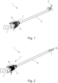
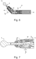
- Figure 1 shows in perspective a medical hand instrument 1 according to an embodiment of the present disclosure.
- the medical hand instrument 1 has a medical motor handpiece 2 according to the disclosure, which has a proximal handle section 4 and which, as in Fig. 1 shown schematically, can be coupled to a drive unit 6.
- the drive unit 6 can also be accommodated in the motor handpiece 2 and supplied with energy via a power supply connection.
- the hand instrument 1 has a distal tool (end effector/effector section) 8, which can be coupled to or decoupled from the motor handpiece 2, in particular to the handle section 4, via a (tool) shaft 10.
- the tool 8 can be designed, for example, as a milling cutter, drill or polishing head.
- the tool 8 can be angled relative to the shaft 10 (in Fig. 1 indicated by arrow C). Ie, as described in more detail below, the tool 8 and the shaft 10 can be angled relative to one another in such a way that a longitudinal axis S1 of the tool 8 and a shaft longitudinal axis S2 of the shaft 10 form an angle not equal to 180°, in particular smaller than 180° (cf . Fig. 6 ).
- a sleeve-shaped control element 12 is provided for this purpose in the hand instrument 1 according to the disclosure.
- the operating element 12 is arranged at a distal end section of the handle section 4 and is rotatable about a longitudinal axis of the handle in a first direction of rotation A and in a second direction of rotation B that is opposite to the first direction of rotation A.
- the motor handpiece 2 has the handle section 4 and the distally arranged operating element 12, which are arranged coaxially to one another, wherein the operating element 12 can be rotated relative to the handle section 4.
- a rotation of the operating element 12 from a neutral zero position, in which the tool 8 is not angled relative to the shaft 10, in the first direction of rotation A causes, as in Fig. 1 shown, an angling of the tool 8 relative to the shaft 10.
- the first direction of rotation A is defined in the hand instrument 1 according to the present disclosure as a rotation of the operating element 12 relative to the handle section 4 to the left.
- the first direction of rotation A in a distal plan view of the tool 8 corresponds to a clockwise rotation of the operating element 12.
- the control element 12 in the hand instrument 1 can also be rotated in the second direction of rotation B, which is opposite to the first direction of rotation A, relative to the handle section 4.
- the second direction of rotation B is defined in the top view of the tool 8 as a rotation of the control element 12 counterclockwise or as a rotation to the right.
- a rotation of the operating element 12 in the second direction of rotation B causes the coupling of the tool 8 to be released with the shaft 10.
- Figs. 3 and 4 show partial sectional views of the hand instrument 1 according to the first embodiment.
- an adjusting pin 14 is arranged in the radial direction of the operating element 12.
- a radially outer end portion of the adjusting pin 14 is received in an axial groove 16, which is formed on an inner circumferential surface of the operating element 12.
- the adjusting pin 14 is received in a rotation transmission sleeve 18.
- the rotation transmission sleeve 18 is connected to the shaft 10 in a rotationally fixed manner, so that a movement of the adjusting pin 14 in the circumferential direction causes a rotation of the rotation transmission sleeve 18 and the shaft 10.
- control element when the control element is rotated, it moves 12 in In the first direction of rotation A or in the second direction of rotation B, the adjusting pin 14 in the axial groove 16 with the control element 12 and, depending on the direction of rotation, causes the tool 8 to be bent or ejected.
- Fig. 5 shows a longitudinal cross section of a distal end section of the hand instrument 1 in a straight shaft shape. Ie the control element 12 is not rotated relative to the handle section 4 (zero position). As a result, the tool 8 and the shaft 10 are not angled and the longitudinal axis S1 of the tool 8 is collinear with the shaft longitudinal axis S2. As in Fig. 5 To recognize, the shaft 10 has a proximal shaft section 20 that faces the handle section 4 and can be coupled to it, and a distal shaft section 22 that can be coupled to the tool 8.
- the proximal shaft section 20 and the distal shaft section 22 are therefore arranged in a line or have an angle of 0° to one another.
- the proximal shaft section 20 is designed essentially tubular and has an end face 24 positioned in the longitudinal axis S2 of the shaft at its distal end section.
- the distal shaft section 22 is also approximately tubular. The tube tapers towards the distal end.
- the distal shaft section 22 has an end face 26 positioned in the longitudinal axis S2 of the shaft at its proximal end section.
- the raised end faces 24, 26 each have an angle of attack of preferably 22.5° to a plane normal to the longitudinal axis S2 of the shaft. If the shaft 10 is in a straight shaft shape or stretched out, the two raised end faces 24, 26 are offset from one another in such a way that the long ends of the raised end faces 24, 26 lie opposite one another in relation to the shaft longitudinal axis S2.
- the employed end faces 24, 26 rest on one another.
- the raised end faces 24, 26 do not necessarily have to have an angle of attack of 22.5°. Angles of attack of, for example, 10°, 18°, 30°, 45° or any other angle of attack are also conceivable.
- the distal shaft portion 22 is designed to be coupled to the tool 8.
- the distal shaft section 22 represents a Tool holder, wherein the tool 8 is accommodated in the tool holder and is rotatably mounted relative to the tool holder, ie the distal shaft section 22.
- a first coupling device 28 is arranged in the distal shaft section 22.
- a second coupling device 30 is provided on the tool 8, which in a coupling state realizes a coupling between the tool 8 and the distal shaft section 22 by interacting with the first coupling device 28 in order to fix the tool 8 in the distal shaft section 22 in the axial direction A.
- a coupling state between the tool 8 and the distal shaft section 22 is shown. That is, the first coupling device 28, which is mounted in/on the distal shaft portion 22, and the second coupling device 30, which is provided on the tool 8, engage with each other.
- the tool 8 has a tool head/effector 32, for example a milling head, and a tool shank 34.
- the tool head 32 and the tool shank 34 are connected to one another in a rotationally fixed manner.
- the tool shaft 34 is rotatably mounted in the distal shaft section 22 using a rolling bearing unit 36.
- a drive shaft 38 extends through the proximal shaft section 20 and is non-rotatably connected to the tool shaft 34 and applies torque from the drive unit 6 to the tool shaft 34 in the form of a torque transmission train.
- the rolling bearing unit 36 has at least one, here exactly two, rolling bearings 40, more precisely ball bearings, which are spaced apart from one another in the axial direction A, but which can alternatively also be designed as plain bearings.
- the rolling bearings 40 are accommodated in a bearing housing 42, which is part of the rolling bearing unit 36.
- the second coupling device 30 is inserted into the bearing housing 42 and is therefore not provided directly on the tool 8.
- the rolling bearing unit 36 and thus also the bearing housing 42 is arranged fixed on the tool shank 34 in the axial direction A.
- the second coupling device 30 it would also be conceivable for the second coupling device 30 to be provided directly on the tool shank 34.
- the second coupling device 30 is designed as an axial securing groove 44 which extends or runs continuously in the circumferential direction of the bearing housing 42.
- the axial securing groove 44 preferably has a semicircular or circular segment-shaped cross section.
- the first coupling device 28, which is provided in the distal shaft section 22, has at least one locking ball 46.
- the diameter of the locking ball 46 is selected so that the locking ball 46 can be accommodated in the axial locking groove 44.
- the axial locking groove 44 preferably completely surrounds at least one section of the locking ball 46 that contacts the axial locking groove 44.
- the locking ball 46 is held in the axial locking groove 44 on its side opposite the axial locking groove 44 by a distal end of a locking pin/slider 48.
- the locking pin 48 is part of the first coupling device 28.
- the locking pin 48 is fixed in the radial direction R.
- the locking pin 48 is displaceable or movable in the distal shaft section 22 in the axial direction.
- the proximal shaft section 20 has a fixed outer tube 50, a ring gear 52 with internal teeth 54, a pinion 56 with external teeth 58 and an eccentric locking bushing 60.
- the ring gear 52 is positioned within the outer tube 50 and the longitudinal axis of the outer tube 50 corresponds to the longitudinal axis of the ring gear 52.
- the outer tube 50 and the ring gear 52 are therefore arranged concentrically.
- the ring gear 52 is connected to the rotation transmission sleeve 18, ie to the operating element 12, via a hollow shaft 62 accommodated in the proximal shaft section 20.
- the outer tube 50 is designed as a stationary tube and therefore does not move.
- the distal end of the outer tube 50 has the raised end face 24.
- the distal end of the outer tube 50 also has a receiving bore 64 and a receiving pin for a rolling bearing 66.
- the outer tube 50 has a groove/groove for the balls of the rolling bearing 66.
- the distal shaft section 22 is mounted on the roller bearing 66.
- the internal toothing 54 meshes with the external toothing 58 of the pinion 56.
- a rotation of the ring gear 52 which is controlled by the operating element 12, is transmitted to the pinion 56.
- the direction of rotation of the pinion 56 is set equal to the direction of rotation of the ring gear 52.
- the pinion 56 is driven by the ring gear 52, but the pinion 56 rotates in the eccentric locking bushing 60.
- the locking bushing 60 is arranged eccentrically to the ring gear 52. This means that the longitudinal axis of the eccentric securing bushing 60 is parallel to the longitudinal axis of the ring gear 52, but the longitudinal axes are not one above the other or offset from one another.
- the distal shaft section 22 has an adjustment bushing 68.
- the adjustment bushing 68 is stored in the receiving bore 64 of the proximal shaft section 20.
- the adjustment bushing 68 is connected to the pinion 56 via a flexible silicone hose 70 in such a way that a rotation of the pinion 56 is transmitted to the adjustment bushing 68.
- the flexible silicone hose 70 is attached to the adjustment bushing 68 and the pinion 56, for example by welding or gluing.
- the adjustment bushing 68 is also positively connected to the distal shaft section 22 via a driving pin (not shown), so that a rotation of the adjustment bushing 68 is transmitted to the distal shaft section 22.
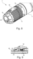
- Fig. 6 shows a longitudinal cross section through the distal end section of the shaft 10, the distal shaft section 22 being angled by 45° relative to the proximal shaft section 20 at a respective angle of attack of the two end faces 24, 26 by 22.5°.
- the distal shaft section 22 is compared to the position in Fig. 5 rotated by 180° around its own longitudinal axis S1.
- the employed end faces 24, 26 lie In this position, they are completely/flatly on top of each other again.
- the long ends of the raised end faces 24, 26 are positioned next to one another.
- the angles of attack of the turned end faces 24, 26 thus add up.
- the distal shaft section 22 is angled by twice the angle of attack of the raised end faces 24, 26 compared to the proximal shaft section 20.
- the driving pin is arranged opposite the securing bushing 60.
- the 45° position represents the reversal point for this construction.
- the adjustment bushing 68 has rotated through 180° in this position. If the ring gear 52, ie the operating element 12, rotates further, the distal shaft section 22 would rotate back into the starting position (zero position).
- Fig. 6 It can be seen that the locking ball 46 is held by the locking pin 48 in the radial direction R in the axial securing groove 44 even when the distal shaft section 22 is angled in the maximum adjustable angular position or maximum angle with respect to the proximal shaft section 20. In this way, the tool 8 is also secured in this angular position in the axial direction A in the distal shaft section by the engagement between the first coupling device 28 and the second coupling device 30.
- the torque train in particular the drive shaft 38, towards the tool shaft 34, which is arranged in the transition region between the distal shaft section 22 and the proximal shaft section 20, is flexible.
- This flexible section of the torque train allows the distal section of the tool shaft 34 with tool head 32 to be angled together with the distal shaft section 22 relative to the torque train in the proximal shaft section 20.
- the flexible section of the torque train is designed so that it can continue to transmit a torque that is exerted on a proximal section of the tool shank 34 to the tool head 32.
- Fig. 7 is a longitudinal sectional view of the distal end portion of the shaft 10 in a release state between the tool 8 and the distal shaft portion 22. That is, in FIG Fig. 7 In the position shown, the first coupling device 28 and the second coupling device 30 are not in active engagement with one another, so that the tool 8 can be removed or changed. In order to release the active engagement of the first coupling device 28 and the second coupling device 30, the operating element 12 is rotated in the second direction of rotation B (cf. Fig. 2 ). As explained in more detail below, the locking ball 46 is no longer accommodated in the axial locking groove 44. Instead, it is held by the locking pin 48 in the radial direction R against an outer peripheral surface of the bearing housing 42.
- the locking pin 48 must move in the axial direction A towards the proximal shaft section 20. This is prevented in the coupling state by the circumferential edge 63 of the proximal shaft section 20. However, the edge 63 is interrupted at one point of a locking pin receiving recess 72.
- the distal shaft section 22 rotates relative to the proximal shaft section 20 in a direction opposite to the bending, for example by (-)18 °, until the locking pin 48 is positioned relative to the proximal shaft section 20 is that it is at the same height as the locking pin receiving recess 72 in the circumferential direction.
- a biasing element 74 which is part of the first coupling device 28, presses the locking pin 48 in the axial direction A towards the proximal shaft section 20.
- the biasing element 74 thus pushes the locking pin 48, more precisely its proximal end, which is designed as a locking projection 76, into the locking pin receiving recess 72.
- the position in which the locking pin 48 is when its locking projection 76 engages the locking pin receiving recess 72 is referred to as the release state or release position.
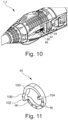
- Fig. 8 shows a perspective view of the distal end section of the motor handpiece 2 according to the first embodiment, without the shaft 10 being coupled to the handle section 4.
- a rotation of the operating element 12 in the first direction of rotation A causes the tool 8 to bend
- a rotation of the operating element 12 in the second direction of rotation B releases the coupling between the tool 8 and the shaft 10, or the distal shaft section 22, by releasing the operative engagement between the first coupling device 28 and the second coupling device 30.
- indicators 78 in the form of arrows which indicate the directions of rotation, are attached to the control element 12.
- the user can quickly identify which direction of rotation corresponds to which function when operating the hand instrument 1. For this are as in Fig. 8 shown, on an outer peripheral surface of the indicator sleeve 80 different angular positions, which each correspond to a defined rotation of the control element 12 in the first direction of rotation A and thus a defined angling of the tool 8 relative to the shaft 10, as well as a lock symbol or a symbol of a with the lock open.
- the user can therefore assign the respective function, namely angling or uncoupling, to the individual directions of rotation A, B.
- the motor handpiece 2 together with the control element 12 thus enables intuitive operation and integration of the two functions.
- a locking slide 82 is arranged on the motor handpiece 2 according to the first embodiment.
- the locking slide 82 is fixed in the operating element 12 in the radial and circumferential directions so that the locking slide 82 can only move in the axial direction relative to the operating element 12 between a (distal) locking and a (proximal) unlocking position.
- In the locking position can the control element 12, as explained in more detail below, cannot be rotated relative to the handle section 4.
- a distal pin section 83 of the locking slide 82 locks in the locking position, as in Fig. 9 shown, with an indicator locking ring 84 accommodated in the indicator sleeve 80.
- the indicator locking ring 84 has a plurality of recesses distributed over the circumference, into which the pin section 83 projects in the locking position, in order to fix or fix the control element 12 in the circumferential direction relative to the handle section 4 .hold on.
- the recesses of the indicator locking ring 84 preferably correspond to the indicators 78 attached to the outer circumferential surface of the indicator sleeve 80. The user can therefore simply set the tool 8 to be angled at a defined angle and fix the angled tool 8 at this angle.
- the locking slide 82 In order to be able to rotate the operating element 12 relative to the handle section 4 to adjust the angle or to release the clutch, the locking slide 82 must therefore be moved from the locking position to the unlocking position, i.e. in the proximal direction.
- the locking slide 82 is biased in the axial direction against the operating element 12 via a spring element 86.
- the spring element 86 is arranged between the locking slide 82 and a stop surface of the operating element 12 in such a way that it presses the locking slide 82 into the locking position, i.e. in the distal direction.
- the spring element 86 consequently exerts an automatic restoring force on the locking slide 82 in order to hold it in the locking position.
- the motor handpiece 2 does not have a spring element 86.
- the user must pull the locking slide 82 in the proximal direction to unlock and actively push it in the distal direction to lock.
- a screw pin in the form of a ball pressure element 88 is provided in the motor handpiece 2.
- This has a spring element 90, which has a ball 92 in the proximal direction against an annular sliding link 94 (see Fig. 11 ) presses.
- Dome-shaped locking recesses 96 are formed on the sliding link 94, which can at least partially accommodate the ball 92.
- the locking recesses 96 are formed in the locking section 98 of the slide gate 94.
- the sliding link 94 includes the stop section 100.
- the stop section 100 is designed with a smooth/flat surface.
- the latching section 98 and the stop section 100 are separated from one another by a first stop 102 and a second stop 104, which protrude from the sliding link 94.
- the first stop 102 contains a drain ramp 106.
- the locking recesses 96 similar to the recesses of the indicator locking ring 84, correspond to defined angles through which the tool 8 can be angled relative to the shaft 10 when the operating element 12 is rotated in a certain way. That is, when the control element 12 is rotated by the defined angle relative to the handle section 4, the ball pressure element 88 rotates with the control element 12 until the defined angle is reached, at which the ball 92 falls into the corresponding locking recess 96 due to the preload force of the spring element 90 the slide gate 94 takes effect. The additional ball pressure element 88 therefore enables haptic feedback for the user when adjusting the angle.
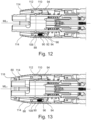
- Fig. 12 shows a sectional view of the motor handpiece 2 in an adjustment/assembly state.
- the control element 12 includes a first adjustment thread 108, which receives the ball pressure element 88. Furthermore, the control element 12 includes a second adjustment thread 110, which receives a stop pin 112.
- the first adjustment thread 108 is positioned so that the ball pressure element 88 contacts the locking section 98 of the slide gate 94.
- the second adjustment thread 110 is positioned so that the stop pin 112 contacts the stop portion 100.
- the first adjustment thread 108 and the second adjustment thread 110 extend longitudinally to a motor handpiece longitudinal axis ML1. In the embodiment shown here, the first adjustment thread 108 extends the second adjustment thread 110 parallel to the motor handpiece longitudinal axis ML1.
- the first adjustment thread 108 and the second adjustment thread 110 are positioned diametrically opposite one another with respect to the motor handpiece longitudinal axis ML1.
- An adjusting bore 114 is formed in a distal extension of the first adjusting thread 108 and the second adjusting thread 110.
- the ball pressure element 88 or the stop pin 112 can be adjusted and brought into contact with the sliding gate 94 with a predetermined torque.
- a screwdriver or the like can be brought into contact with the stop pin 112 and/or the ball pressure element 88 through the adjustment hole and the stop pin 112 and/or the ball pressure element 88 in a mounted state in a direction of the motor handpiece longitudinal extension, preferably in a direction of the motor handpiece longitudinal axis, be adjusted.
- the adjustment holes 114 are each inclined towards the motor handpiece longitudinal axis ML1.
- An adhesive can be applied (after adjustment) to the stop pin 112 and the ball pressure element 88 through the adjustment holes 114. In this way, the stop pin 112 and the ball pressure element 88 can be fixed in the adjusted state.
- Fig. 13 shows a sectional view of the motor handpiece 2 in an assembled state.
- the indicator sleeve/indicator ring/locking ring 80 closes the adjustment bore 114 in the distal direction.
- the indicator ring/locking ring 80 is preferably fixed on the motor handpiece 2 with a snap ring 116 in such a way that it can only be removed using a tool. In this way, it can be prevented that an adjustment of the stop pin 112 and/or the ball pressure element 88 is manipulated/adjusted by an unauthorized user.
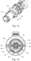
- Fig. 14 and Fig. 15 illustratively shows the motor handpiece 2 without the control element 12.
- the stop pin 112 and the ball pressure element 88 are arranged on the diameter of the sliding link 94.
- the ball pressure element 88 and the stop pin 112 are arranged so that their distance is maximum.
- the ball pressure element 88 and the Stop pin 112 arranged diametrically opposite.
- the arrangement of the locking recesses 96 on the locking section 98 of the sliding gate 94 corresponds to the predefined angles of the tool 8. The arrangement explicitly does not have to be evenly distributed over the locking section 98 of the sliding gate 94.
- Fig. 16 is a detailed view of the stop pin 112.
- the stop pin 112 includes a screw head drive 118, which in the embodiment shown here is designed as a slotted screw head drive.
- the stop pin further includes an external thread 120, which is provided and designed to engage in the adjusting thread 110 of the operating element 12.
- the stop element 122 is formed on an end section of the stop pin 112 facing away from the screw head drive 118.
- the stop element 122 has a substantially cylindrical shape.
- the stop pin 112 contains the sliding section 124, which is provided and designed to slide on the sliding link 94.
- the sliding section 124 is spherical in shape in order to minimize a contact area between the sliding section 124 and the sliding link 94.
- Fig. 17 is a detailed view of the ball pressure element 88.
- the ball pressure element 88 includes a screw head drive 118, which in the embodiment shown here is designed as a slotted screw head drive.
- the stop pin further includes an external thread 120 which is provided and designed to engage in the adjustment thread 110 of the operating element 12.
- a spring section 126 is formed on an end section of the ball pressure element 88 facing away from the screw head drive 118.
- the spring section 126 is designed as a hollow cylinder, in the interior of which the spring element 90 and the ball 92 are guided (cf. Fig. 10 , Fig. 12 and Fig. 13 ).
- the screw head drive 118 of the ball pressure element 88 can be designed as a screw stamp, via which a preload force on the spring element 90 can be adjusted.
- a single screw pin can be designed, which takes on the function of both the stop pin 112 and the ball pressure element 88.
- the sliding gate 94 can be designed with only one of the first stop 102 or the second stop 104.
Landscapes
- Health & Medical Sciences (AREA)
- Surgery (AREA)
- Life Sciences & Earth Sciences (AREA)
- Biomedical Technology (AREA)
- Medical Informatics (AREA)
- Orthopedic Medicine & Surgery (AREA)
- Oral & Maxillofacial Surgery (AREA)
- Engineering & Computer Science (AREA)
- Dentistry (AREA)
- Heart & Thoracic Surgery (AREA)
- Nuclear Medicine, Radiotherapy & Molecular Imaging (AREA)
- Molecular Biology (AREA)
- Animal Behavior & Ethology (AREA)
- General Health & Medical Sciences (AREA)
- Public Health (AREA)
- Veterinary Medicine (AREA)
- Dental Tools And Instruments Or Auxiliary Dental Instruments (AREA)
Applications Claiming Priority (1)
| Application Number | Priority Date | Filing Date | Title |
|---|---|---|---|
| DE102022119980.0A DE102022119980A1 (de) | 2022-08-09 | 2022-08-09 | Medizinisches Motorhandstück mit Rast- und/oder Anschlageinheit |
Publications (1)
| Publication Number | Publication Date |
|---|---|
| EP4321107A1 true EP4321107A1 (fr) | 2024-02-14 |
Family
ID=87555057
Family Applications (1)
| Application Number | Title | Priority Date | Filing Date |
|---|---|---|---|
| EP23189302.5A Pending EP4321107A1 (fr) | 2022-08-09 | 2023-08-02 | Pièce à main motorisée médicale dotée d'une unité d'arrêt et/ou de butée |
Country Status (2)
| Country | Link |
|---|---|
| EP (1) | EP4321107A1 (fr) |
| DE (1) | DE102022119980A1 (fr) |
Cited By (2)
| Publication number | Priority date | Publication date | Assignee | Title |
|---|---|---|---|---|
| CN117982199A (zh) * | 2024-04-02 | 2024-05-07 | 赛微医疗科技(上海)有限公司 | 锁止结构、手柄、取栓装置及鞘管组件 |
| CN119770119A (zh) * | 2024-12-31 | 2025-04-08 | 重庆西山科技股份有限公司 | 护鞘无级调节机构及医用磨削装置 |
Citations (8)
| Publication number | Priority date | Publication date | Assignee | Title |
|---|---|---|---|---|
| US7585300B2 (en) | 2003-12-19 | 2009-09-08 | Spinascope, Inc. | Dissecting high speed burr for spinal surgery |
| EP2489315A1 (fr) * | 2011-02-15 | 2012-08-22 | Karl Storz GmbH & Co. KG | Instrument médical |
| US8303594B2 (en) | 2008-12-30 | 2012-11-06 | Howmedica Osteonics Corp. | Method and apparatus for removal of tissue |
| EP2759270A1 (fr) * | 2013-01-25 | 2014-07-30 | Karl Storz GmbH & Co. KG | Instrument médical |
| US9597093B2 (en) | 2014-06-10 | 2017-03-21 | Howmedica Osteonics Corp. | Temporarily fixable angled drill |
| US10070872B2 (en) | 2014-05-02 | 2018-09-11 | The Catholic University Of Korea Industry-Academic Cooperation Foundation | Medical motor drill with angle adjusting function |
| DE102017010033A1 (de) | 2017-10-27 | 2019-05-02 | Joimax Gmbh | Medizinische Vorrichtung |
| US11284907B2 (en) * | 2014-06-10 | 2022-03-29 | Medos International Sarl | Retro-cutting instrument with adjustable limit setting |
-
2022
- 2022-08-09 DE DE102022119980.0A patent/DE102022119980A1/de active Pending
-
2023
- 2023-08-02 EP EP23189302.5A patent/EP4321107A1/fr active Pending
Patent Citations (8)
| Publication number | Priority date | Publication date | Assignee | Title |
|---|---|---|---|---|
| US7585300B2 (en) | 2003-12-19 | 2009-09-08 | Spinascope, Inc. | Dissecting high speed burr for spinal surgery |
| US8303594B2 (en) | 2008-12-30 | 2012-11-06 | Howmedica Osteonics Corp. | Method and apparatus for removal of tissue |
| EP2489315A1 (fr) * | 2011-02-15 | 2012-08-22 | Karl Storz GmbH & Co. KG | Instrument médical |
| EP2759270A1 (fr) * | 2013-01-25 | 2014-07-30 | Karl Storz GmbH & Co. KG | Instrument médical |
| US10070872B2 (en) | 2014-05-02 | 2018-09-11 | The Catholic University Of Korea Industry-Academic Cooperation Foundation | Medical motor drill with angle adjusting function |
| US9597093B2 (en) | 2014-06-10 | 2017-03-21 | Howmedica Osteonics Corp. | Temporarily fixable angled drill |
| US11284907B2 (en) * | 2014-06-10 | 2022-03-29 | Medos International Sarl | Retro-cutting instrument with adjustable limit setting |
| DE102017010033A1 (de) | 2017-10-27 | 2019-05-02 | Joimax Gmbh | Medizinische Vorrichtung |
Cited By (2)
| Publication number | Priority date | Publication date | Assignee | Title |
|---|---|---|---|---|
| CN117982199A (zh) * | 2024-04-02 | 2024-05-07 | 赛微医疗科技(上海)有限公司 | 锁止结构、手柄、取栓装置及鞘管组件 |
| CN119770119A (zh) * | 2024-12-31 | 2025-04-08 | 重庆西山科技股份有限公司 | 护鞘无级调节机构及医用磨削装置 |
Also Published As
| Publication number | Publication date |
|---|---|
| DE102022119980A1 (de) | 2024-02-15 |
Similar Documents
| Publication | Publication Date | Title |
|---|---|---|
| EP3528688B1 (fr) | Dispositif médical | |
| EP1484024B1 (fr) | Instrument chirurgical avec poignée et un système de réglage de son point-zéro | |
| EP1464289B1 (fr) | Instrument chirurgical, dans lequel les mouvements de la tête et de l'outil sont découplés | |
| EP1649816B1 (fr) | Instrument endoscopique déviable | |
| DE10358554B4 (de) | Chirurgisches Instrument zum Sezieren von Knochen oder anderem Gewebe mit Teleskopaufsatz | |
| DE19707373C1 (de) | Bajonettkupplung zum lösbaren Verbinden zweier Rohrschaftinstrumente oder -instrumententeile | |
| EP2305145B1 (fr) | Système de pinces médicales démontables | |
| EP2510887B1 (fr) | Outil pour un instrument de chirurgie micro-invasive | |
| DE102021119528B4 (de) | Lagerungsanordnung einer Taumelscheibe in einem Lenkgetriebebauteil und chirurgisches Instrument | |
| EP1486172A1 (fr) | Instrument chirurgical | |
| EP4321107A1 (fr) | Pièce à main motorisée médicale dotée d'une unité d'arrêt et/ou de butée | |
| EP4351448A1 (fr) | Tige pliable pour un instrument médical à main | |
| EP1905369B1 (fr) | Tournevis pour la manipulation d'une vis dans un corps humain ou animal | |
| EP3352713B1 (fr) | Support dynamique d'articulation | |
| EP2910202B1 (fr) | Instrument destiné à exécuter des interventions médicales | |
| WO2003101316A1 (fr) | Instrument medical | |
| EP4321109A1 (fr) | Pièce à main motorisée médicale dotée d'une bague de réglage angulaire et instrument médical manuel | |
| DE102022119979A1 (de) | Medizinisches Motorhandstück für 2-in-1-Bedienung sowie medizinisches Handinstrument mit 2-in-1-Bedienung | |
| EP4321108A1 (fr) | Pièce à main motorisée dotée d'un élément de commande rotatif et instrument médical manuel | |
| EP4376732B1 (fr) | Instrument chirurgical et son mécanisme de direction | |
| EP4376731B1 (fr) | Ensemble palier d'un plateau oscillant dans un composant de mécanisme de direction, et instrument chirurgical | |
| WO2023194131A1 (fr) | Système d'outil médical | |
| EP4504076A1 (fr) | Outil chirurgical souple équipé d'un ensemble palier intégré | |
| EP4565151B1 (fr) | Poignée en forme de pistolet chirurgical, et instrument chirurgical ayant une poignée en forme de pistolet | |
| EP4321110A1 (fr) | Accouplement de tige et procédé d'assemblage associé |
Legal Events
| Date | Code | Title | Description |
|---|---|---|---|
| PUAI | Public reference made under article 153(3) epc to a published international application that has entered the european phase |
Free format text: ORIGINAL CODE: 0009012 |
|
| STAA | Information on the status of an ep patent application or granted ep patent |
Free format text: STATUS: THE APPLICATION HAS BEEN PUBLISHED |
|
| AK | Designated contracting states |
Kind code of ref document: A1 Designated state(s): AL AT BE BG CH CY CZ DE DK EE ES FI FR GB GR HR HU IE IS IT LI LT LU LV MC ME MK MT NL NO PL PT RO RS SE SI SK SM TR |
|
| STAA | Information on the status of an ep patent application or granted ep patent |
Free format text: STATUS: REQUEST FOR EXAMINATION WAS MADE |
|
| 17P | Request for examination filed |
Effective date: 20240813 |
|
| RBV | Designated contracting states (corrected) |
Designated state(s): AL AT BE BG CH CY CZ DE DK EE ES FI FR GB GR HR HU IE IS IT LI LT LU LV MC ME MK MT NL NO PL PT RO RS SE SI SK SM TR |