EP2910268A1 - Inhalator und Inhalatorsatz - Google Patents
Inhalator und Inhalatorsatz Download PDFInfo
- Publication number
- EP2910268A1 EP2910268A1 EP14156519.2A EP14156519A EP2910268A1 EP 2910268 A1 EP2910268 A1 EP 2910268A1 EP 14156519 A EP14156519 A EP 14156519A EP 2910268 A1 EP2910268 A1 EP 2910268A1
- Authority
- EP
- European Patent Office
- Prior art keywords
- housing
- aerosol generator
- inhalator
- base
- socket
- Prior art date
- Legal status (The legal status is an assumption and is not a legal conclusion. Google has not performed a legal analysis and makes no representation as to the accuracy of the status listed.)
- Withdrawn
Links
- 239000000443 aerosol Substances 0.000 claims abstract description 145
- 239000012530 fluid Substances 0.000 claims abstract description 51
- 238000004140 cleaning Methods 0.000 claims description 44
- 239000012528 membrane Substances 0.000 claims description 35
- 230000005484 gravity Effects 0.000 claims description 14
- 238000002663 nebulization Methods 0.000 claims description 7
- 239000000243 solution Substances 0.000 description 8
- 238000000034 method Methods 0.000 description 6
- 230000009286 beneficial effect Effects 0.000 description 4
- 210000002105 tongue Anatomy 0.000 description 4
- 239000007788 liquid Substances 0.000 description 3
- 230000007246 mechanism Effects 0.000 description 3
- 238000000926 separation method Methods 0.000 description 3
- 230000001419 dependent effect Effects 0.000 description 2
- 230000000694 effects Effects 0.000 description 2
- 238000011010 flushing procedure Methods 0.000 description 2
- 238000004519 manufacturing process Methods 0.000 description 2
- 230000013011 mating Effects 0.000 description 2
- 230000003287 optical effect Effects 0.000 description 2
- 101150034459 Parpbp gene Proteins 0.000 description 1
- FAPWRFPIFSIZLT-UHFFFAOYSA-M Sodium chloride Chemical compound [Na+].[Cl-] FAPWRFPIFSIZLT-UHFFFAOYSA-M 0.000 description 1
- 239000004480 active ingredient Substances 0.000 description 1
- 239000003708 ampul Substances 0.000 description 1
- 238000005452 bending Methods 0.000 description 1
- 238000010276 construction Methods 0.000 description 1
- 239000004615 ingredient Substances 0.000 description 1
- 238000003780 insertion Methods 0.000 description 1
- 230000037431 insertion Effects 0.000 description 1
- 238000002156 mixing Methods 0.000 description 1
- 238000012544 monitoring process Methods 0.000 description 1
- 239000003186 pharmaceutical solution Substances 0.000 description 1
- 238000003825 pressing Methods 0.000 description 1
- 238000007789 sealing Methods 0.000 description 1
- 239000011780 sodium chloride Substances 0.000 description 1
- 238000005476 soldering Methods 0.000 description 1
- 230000001225 therapeutic effect Effects 0.000 description 1
- 238000003466 welding Methods 0.000 description 1
Images

Classifications
-
- A—HUMAN NECESSITIES
- A61—MEDICAL OR VETERINARY SCIENCE; HYGIENE
- A61M—DEVICES FOR INTRODUCING MEDIA INTO, OR ONTO, THE BODY; DEVICES FOR TRANSDUCING BODY MEDIA OR FOR TAKING MEDIA FROM THE BODY; DEVICES FOR PRODUCING OR ENDING SLEEP OR STUPOR
- A61M11/00—Sprayers or atomisers specially adapted for therapeutic purposes
-
- A—HUMAN NECESSITIES
- A61—MEDICAL OR VETERINARY SCIENCE; HYGIENE
- A61M—DEVICES FOR INTRODUCING MEDIA INTO, OR ONTO, THE BODY; DEVICES FOR TRANSDUCING BODY MEDIA OR FOR TAKING MEDIA FROM THE BODY; DEVICES FOR PRODUCING OR ENDING SLEEP OR STUPOR
- A61M11/00—Sprayers or atomisers specially adapted for therapeutic purposes
- A61M11/005—Sprayers or atomisers specially adapted for therapeutic purposes using ultrasonics
-
- A—HUMAN NECESSITIES
- A61—MEDICAL OR VETERINARY SCIENCE; HYGIENE
- A61M—DEVICES FOR INTRODUCING MEDIA INTO, OR ONTO, THE BODY; DEVICES FOR TRANSDUCING BODY MEDIA OR FOR TAKING MEDIA FROM THE BODY; DEVICES FOR PRODUCING OR ENDING SLEEP OR STUPOR
- A61M15/00—Inhalators
- A61M15/0001—Details of inhalators; Constructional features thereof
- A61M15/0021—Mouthpieces therefor
-
- A—HUMAN NECESSITIES
- A61—MEDICAL OR VETERINARY SCIENCE; HYGIENE
- A61M—DEVICES FOR INTRODUCING MEDIA INTO, OR ONTO, THE BODY; DEVICES FOR TRANSDUCING BODY MEDIA OR FOR TAKING MEDIA FROM THE BODY; DEVICES FOR PRODUCING OR ENDING SLEEP OR STUPOR
- A61M15/00—Inhalators
- A61M15/0085—Inhalators using ultrasonics
-
- A—HUMAN NECESSITIES
- A61—MEDICAL OR VETERINARY SCIENCE; HYGIENE
- A61M—DEVICES FOR INTRODUCING MEDIA INTO, OR ONTO, THE BODY; DEVICES FOR TRANSDUCING BODY MEDIA OR FOR TAKING MEDIA FROM THE BODY; DEVICES FOR PRODUCING OR ENDING SLEEP OR STUPOR
- A61M16/00—Devices for influencing the respiratory system of patients by gas treatment, e.g. ventilators; Tracheal tubes
- A61M16/04—Tracheal tubes
-
- A—HUMAN NECESSITIES
- A61—MEDICAL OR VETERINARY SCIENCE; HYGIENE
- A61M—DEVICES FOR INTRODUCING MEDIA INTO, OR ONTO, THE BODY; DEVICES FOR TRANSDUCING BODY MEDIA OR FOR TAKING MEDIA FROM THE BODY; DEVICES FOR PRODUCING OR ENDING SLEEP OR STUPOR
- A61M16/00—Devices for influencing the respiratory system of patients by gas treatment, e.g. ventilators; Tracheal tubes
- A61M16/06—Respiratory or anaesthetic masks
-
- A—HUMAN NECESSITIES
- A61—MEDICAL OR VETERINARY SCIENCE; HYGIENE
- A61M—DEVICES FOR INTRODUCING MEDIA INTO, OR ONTO, THE BODY; DEVICES FOR TRANSDUCING BODY MEDIA OR FOR TAKING MEDIA FROM THE BODY; DEVICES FOR PRODUCING OR ENDING SLEEP OR STUPOR
- A61M15/00—Inhalators
- A61M15/0001—Details of inhalators; Constructional features thereof
- A61M15/0013—Details of inhalators; Constructional features thereof with inhalation check valves
- A61M15/0015—Details of inhalators; Constructional features thereof with inhalation check valves located upstream of the dispenser, i.e. not traversed by the product
-
- A—HUMAN NECESSITIES
- A61—MEDICAL OR VETERINARY SCIENCE; HYGIENE
- A61M—DEVICES FOR INTRODUCING MEDIA INTO, OR ONTO, THE BODY; DEVICES FOR TRANSDUCING BODY MEDIA OR FOR TAKING MEDIA FROM THE BODY; DEVICES FOR PRODUCING OR ENDING SLEEP OR STUPOR
- A61M16/00—Devices for influencing the respiratory system of patients by gas treatment, e.g. ventilators; Tracheal tubes
- A61M16/0003—Accessories therefor, e.g. sensors, vibrators, negative pressure
- A61M2016/0015—Accessories therefor, e.g. sensors, vibrators, negative pressure inhalation detectors
-
- A—HUMAN NECESSITIES
- A61—MEDICAL OR VETERINARY SCIENCE; HYGIENE
- A61M—DEVICES FOR INTRODUCING MEDIA INTO, OR ONTO, THE BODY; DEVICES FOR TRANSDUCING BODY MEDIA OR FOR TAKING MEDIA FROM THE BODY; DEVICES FOR PRODUCING OR ENDING SLEEP OR STUPOR
- A61M2205/00—General characteristics of the apparatus
- A61M2205/35—Communication
-
- A—HUMAN NECESSITIES
- A61—MEDICAL OR VETERINARY SCIENCE; HYGIENE
- A61M—DEVICES FOR INTRODUCING MEDIA INTO, OR ONTO, THE BODY; DEVICES FOR TRANSDUCING BODY MEDIA OR FOR TAKING MEDIA FROM THE BODY; DEVICES FOR PRODUCING OR ENDING SLEEP OR STUPOR
- A61M2205/00—General characteristics of the apparatus
- A61M2205/50—General characteristics of the apparatus with microprocessors or computers
-
- A—HUMAN NECESSITIES
- A61—MEDICAL OR VETERINARY SCIENCE; HYGIENE
- A61M—DEVICES FOR INTRODUCING MEDIA INTO, OR ONTO, THE BODY; DEVICES FOR TRANSDUCING BODY MEDIA OR FOR TAKING MEDIA FROM THE BODY; DEVICES FOR PRODUCING OR ENDING SLEEP OR STUPOR
- A61M2205/00—General characteristics of the apparatus
- A61M2205/58—Means for facilitating use, e.g. by people with impaired vision
- A61M2205/581—Means for facilitating use, e.g. by people with impaired vision by audible feedback
-
- A—HUMAN NECESSITIES
- A61—MEDICAL OR VETERINARY SCIENCE; HYGIENE
- A61M—DEVICES FOR INTRODUCING MEDIA INTO, OR ONTO, THE BODY; DEVICES FOR TRANSDUCING BODY MEDIA OR FOR TAKING MEDIA FROM THE BODY; DEVICES FOR PRODUCING OR ENDING SLEEP OR STUPOR
- A61M2205/00—General characteristics of the apparatus
- A61M2205/58—Means for facilitating use, e.g. by people with impaired vision
- A61M2205/586—Ergonomic details therefor, e.g. specific ergonomics for left or right-handed users
-
- A—HUMAN NECESSITIES
- A61—MEDICAL OR VETERINARY SCIENCE; HYGIENE
- A61M—DEVICES FOR INTRODUCING MEDIA INTO, OR ONTO, THE BODY; DEVICES FOR TRANSDUCING BODY MEDIA OR FOR TAKING MEDIA FROM THE BODY; DEVICES FOR PRODUCING OR ENDING SLEEP OR STUPOR
- A61M2205/00—General characteristics of the apparatus
- A61M2205/82—Internal energy supply devices
- A61M2205/8206—Internal energy supply devices battery-operated
-
- A—HUMAN NECESSITIES
- A61—MEDICAL OR VETERINARY SCIENCE; HYGIENE
- A61M—DEVICES FOR INTRODUCING MEDIA INTO, OR ONTO, THE BODY; DEVICES FOR TRANSDUCING BODY MEDIA OR FOR TAKING MEDIA FROM THE BODY; DEVICES FOR PRODUCING OR ENDING SLEEP OR STUPOR
- A61M2209/00—Ancillary equipment
- A61M2209/06—Packaging for specific medical equipment
-
- A—HUMAN NECESSITIES
- A61—MEDICAL OR VETERINARY SCIENCE; HYGIENE
- A61M—DEVICES FOR INTRODUCING MEDIA INTO, OR ONTO, THE BODY; DEVICES FOR TRANSDUCING BODY MEDIA OR FOR TAKING MEDIA FROM THE BODY; DEVICES FOR PRODUCING OR ENDING SLEEP OR STUPOR
- A61M2209/00—Ancillary equipment
- A61M2209/10—Equipment for cleaning
-
- B—PERFORMING OPERATIONS; TRANSPORTING
- B05—SPRAYING OR ATOMISING IN GENERAL; APPLYING FLUENT MATERIALS TO SURFACES, IN GENERAL
- B05B—SPRAYING APPARATUS; ATOMISING APPARATUS; NOZZLES
- B05B17/00—Apparatus for spraying or atomising liquids or other fluent materials, not covered by the preceding groups
- B05B17/04—Apparatus for spraying or atomising liquids or other fluent materials, not covered by the preceding groups operating with special methods
- B05B17/06—Apparatus for spraying or atomising liquids or other fluent materials, not covered by the preceding groups operating with special methods using ultrasonic or other kinds of vibrations
- B05B17/0607—Apparatus for spraying or atomising liquids or other fluent materials, not covered by the preceding groups operating with special methods using ultrasonic or other kinds of vibrations generated by electrical means, e.g. piezoelectric transducers
- B05B17/0638—Apparatus for spraying or atomising liquids or other fluent materials, not covered by the preceding groups operating with special methods using ultrasonic or other kinds of vibrations generated by electrical means, e.g. piezoelectric transducers spray being produced by discharging the liquid or other fluent material through a plate comprising a plurality of orifices
- B05B17/0646—Vibrating plates, i.e. plates being directly subjected to the vibrations, e.g. having a piezoelectric transducer attached thereto
Definitions
- the present invention relates to an inhalator and an inhalator set.
- the present invention relates to inhalators that are configured to nebulize a fluid for producing an aerosol to be inhaled by an individual.
- the aerosol will contain an active ingredient, particularly a pharmaceutical ingredient for therapeutic purposes.
- non-pharmaceutical solutions such as saline solutions may be used.
- Such inhalators are generally configured of an aerosol generator unit and a controller unit containing the controller for controlling operation of the aerosol generator as part of the aerosol generator unit.
- a controller unit containing the controller for controlling operation of the aerosol generator as part of the aerosol generator unit.
- One concept suggests to accommodate each unit in separate housings and electrically connect the controller and the aerosol generator by use of a relatively long (e.g. 1m) cable.
- Such inhalators are for example distributed by Pari ® as eflow ® Rapid or distributed by Aerogen ® as Aeroneb ® Go. Another disclosure in this regard may be found in US 2011/0108025 A1 . Even though this kind of connection has proven beneficial in many regards, the use of a cable is under certain circumstances considered inconvenient for the user.
- a latch comprising a lug having an opening at one end and integrally formed with one of the housing parts, and a protrusion at the other of the housing parts.
- the opening of the lug receives the protrusion for locking the parts together.
- the lug was in general integrally formed with the housing part using an integral hinge. Those integral hinges, however, had the drawback, that a "predetermined breaking line" was created at the hinge risking separation of the lug from the housing part after repeated use.
- Another object of the present invention is the provision of an inhalator for direct connection to an aerosol generator unit without the use of a cable and preferably still enabling back-flushing of the aerosol generator by means of a cleaning unit, and of a corresponding inhalator set.
- An even further object of the present invention is the provision of an inhalator in which two housing parts of the inhalator may be securely connected and locked by means of a latch with an increased lifetime of the latch.
- an inhalator in which the housing containing the controller and particularly a portion of the housing actually containing a portion of the controller extends above and beyond the housing containing the aerosol generator and preferably the aerosol generator itself and even more preferred a fluid container for containing a fluid to be nebulized.
- the inhalator basically assumes a shape similar to the letter "L" with the vertical leg formed by the housing or part of the housing accommodating the controller and the horizontal leg formed by the housing or part of the housing containing the aerosol generator.
- an inhalator which comprises an aerosol generator.
- the aerosol generator is a device that enables the production of an aerosol from a fluid, particularly a liquid. This may preferably be achieved by using a vibratable membrane having a plurality of apertures through which the fluid is passed for nebulization. Such vibratable membranes are generally connected to a piezoelectric actuator for active vibration of the membrane (see e.g. EP 1 852 896 A1 incorporated in its entirety by reference). The vibration causes the fluid to pass through the apertures being nebulized on an opposite side of the membrane as compared to that side at which the fluid is applied.
- the fluid may be applied via a fluid container configured to contain the fluid to be nebulized.
- the fluid container may be a space defined in a housing of the inhalator and being a non-separable part of the housing. Yet, the fluid container may also be formed by an insertable and replaceable ampoule or other container that may be coupled or uncoupled from the housing of the inhalator.
- the fluid container serves for supplying a fluid to be nebulized to the aerosol generator and, hence, the fluid container may be limited at one side by the aerosol generator, particularly the membrane thereof.
- the inhalator comprises a controller.
- This controller is configured to control operation of the aerosol generator including starting and stopping of the aerosol production.
- the control may as well involve further functions such as detecting and processing of parameters, e.g. inhalation by a patient, amount of fluid available, etc. which may be used for monitoring and/or triggering the operation of the aerosol generator.
- the inhalator comprises a housing accommodating at least the aerosol generator and the controller.
- the housing has a base for supporting the housing on a horizontal surface, particularly in case the inhalator is not in use.
- the inhalator is to be placed on the horizontal surface in the same orientation as during inhalation.
- Easy attachment of the fluid container, if configured replaceable, or easy filling of the fluid container, if integrally formed with the housing, should be enabled in this orientation. In the latter case, it is likely that a lid is attached to the fluid container which is to be removed for filling the fluid container.
- the lid should be easily accessible for removal and the opening of the fluid container should be directed vertically upward to enable easy filling when the inhalator is supported by its base on the horizontal surface.
- a portion of the housing accommodating at least a portion of the controller is arranged further away from the base than the aerosol generator as seen in a vertical direction, when the base is supported on the horizontal surface.
- a portion of the housing accommodating at least a portion of the controller also includes another portion of the housing which extends from that portion and does not accommodate the controller or a portion thereof which is arranged even further away from the base than said portion. That is, said portion does not necessarily form the top of the inhalator, even though this is preferred.
- this configuration provides for an ergonomic inhalator that may be easily gripped and held during inhalation by an individual or patient so that the inhalator is perceived comfortable and convenient to use.
- the inhalator is a so-called membrane inhalator, wherein the aerosol generator has a vibratable membrane with a plurality of apertures through which the fluid is passed for nebulization. It is even more preferred that said portion of the housing which accommodates the portion of the controller is arranged further away from the base than the membrane as seen in the vertical direction, when the base is supported on the horizontal surface. This enables an inhalator with a relatively low total height as compared to the prior art even though the controller and the aerosol generator are accommodated in a common housing and not connected via a cable.
- the membrane is oriented substantially parallel to the base of the housing. That is, during use or when the inhalator is supported, the membrane is oriented substantially horizontal.
- the term "substantially” in this regard indicates that the orientation does not need to be exactly parallel or horizontal. Rather, a variation in the range of ⁇ 30°, preferably ⁇ 15° would still be considered within the scope of this term.
- the controller may comprise a circuit board and at least a portion of the circuit board is accommodated in said portion of the housing.
- at least a portion of the circuit board namely that portion which is accommodated in said portion of the housing which is arranged further away from the base and preferably the aerosol generator, is also arranged further away from the base and preferably the aerosol generator as seen in the vertical direction, when the base is supported on the horizontal surface.
- the prior art reveals several possibilities to apply the liquid to the aerosol generator, such as by capillary forces, wicks or pumps, which actively convey the fluid to the aerosol generator.
- the present inhalator is particularly designed for an aerosol generator that is gravity fed. "Gravity fed” defines that the fluid is flown to the aerosol generator, i.e. applied to the aerosol generator (its membrane, if present), primarily by gravitational force. This very much simplifies the construction of the inhalator as no additional elements such as pumps or wicks are required.
- a fluid container containing the fluid to be nebulized may be arranged on an opposite side of the aerosol generator (its membrane, if present) relative to the base, that is above the aerosol generator. It is preferred that said portion of the housing is even arranged further away from the base than the fluid container as seen in the vertical direction, when the base is supported on the horizontal surface.
- the inhalator is preferably configured so as to lower the center of gravity.
- a battery compartment to supply power to the controller has contacts to receive and electrically contact one or more batteries.
- the contacts are configured so that the battery/-ies are located closer to the base than to a top of the inhalator at an opposite side of the base and furthest away from the base.
- an inhalator in which the center of gravity of the inhalator is closer to the base than to the top is preferred.
- a horizontal line and contacting the lowest point of the housing of the inhalator at the base and another horizontal line contacting the highest point of the housing of the inhalator at the top defines the height and the center of gravity is located closer to the lower line than to the upper line.
- the center of gravity is located in the lower third of the height, preferably in the lower quarter of the height.
- the portion of the housing accommodating at least a portion of the controller forms a handle so that the inhalator may be held during inhalation with the base facing downward.
- the grip may be exclusively formed by said portion, but it is preferred that said portion is only a part of the grip.
- the inhalator may comprise an outlet for delivery of the nebulized fluid to a patient.
- the outlet is preferably located closer to the base than the aerosol generator and said portion of the housing as well as the fluid container.
- the outlet has a center axis which is substantially parallel to the orientation of a membrane of the aerosol generator. That is, the center axis of the outlet and a center axis of the membrane are angled relative to each other. This in addition to the orientation of the membrane parallel to the base enables the configuration of an inhalator with a low height, which is also advantageous regarding stability of the inhalator when placed on a horizontal surface.
- the housing of the inhalator is separated into a first housing accommodating the controller and a second housing accommodating the aerosol generator, wherein the first and second housing being detachably connected.
- the first and second housing are directly connected to each other.
- one of the first and second housings comprises a socket and the other of the first and second housings comprises a plug detachable from and electrically connected (connectable) to the socket.
- plug and socket connectors are usually made up of a male plug (typically pin contacts) and a female receptacle (typically socket contacts).
- the term is not limited to this understanding. Rather, the socket is considered as the "non-movable part" of the connector into which the plug, as the “movable part” of the connector is introduced no matter whether the socket is female or male and the plug is male or female. Further, also hermaphroditic do also fall within this scope.
- the socket or the plug is configured to receive the plug or the socket at least in two different orientations.
- the two different orientations are preferably rotated by 180° relative to a center axis (preferably a symmetry axis) of the socket.
- first and second housings may be required to lock the first and second housings to each other.
- a latch In the prior art, such latch was configured by a lug integral with and extending from one of the first and second housings and having a hole engaged with a protrusion integral with the other of the first and second housings.
- an integral hinge was provided in order to engage and disengage the lug with the protrusion. This is of course also conceivable with respect to the present invention. Yet, an integral hinge being exposed to repeated bending-stress bears the risk that after a certain lifetime, the lug breaks and separates from the housing at the integral hinge forming a "predetermined break line".
- a lug is suggested having a flexible area which extends a certain distance in a direction away from the connection to one of the first and second housings towards the hole.
- the lug may not be rotated about a strict axis or hinge, but may be flexed in the flexible area.
- This flexure of the lug relative to the one of the first and second housings enables disengagement from and engagement with the protrusion.
- the "predetermined break line" which was disadvantageous in prior art systems is avoided and separation of the lug can be securely prevented.
- the lug remains flexed after the disengagement from the protrusion, meaning that it does not spring back into the engagement position. For engagement, it is again necessary to actively bend the lug in the flexible area to engage it with the protrusion by flexure. This is advantageous from the perspective, that a user perceives an optical and preferably also an audible feedback that the two housings are securely connected and locked.
- an inhalator comprising a controller unit and an aerosol generator unit.
- the controller unit comprises a first housing, a controller accommodated in the first housing and a socket electrically connected to the controller.
- the socket may be accessible via an opening in the first housing or protrude from the first housing.
- the controller unit may of course comprise additional elements such as another socket for connection to a personal computer or to a power source by means of e.g. a USB cable.
- a battery compartment may be contained in the controller housing as mentioned above.
- the controller housing may comprise an ON/OFF button to start and stop inhalation and cooperating with a switch of the controller.
- the aerosol generator unit comprises a second housing and an aerosol generator accommodated in the second housing. Further, a plug is provided which is configured to detachably connect with the socket of the controller unit. The plug is electrically connected to the aerosol generator and may be accessible via an opening in the second housing or protrude from the second housing.
- the controller unit and the aerosol generator unit are directly connectable without the need of a cable but by directly mating the plug and the socket.
- the controller unit and the aerosol generator unit may be configured as described above.
- the socket or the plug is configured to receive the plug or the socket in at least two different orientations, preferably orientations that are offset by 180° for establishing an electrical connection between the plug and the socket.
- the socket may comprise a circuit board having two opposite sides and each side comprises a conductive path for electrical connection to electrical contacts of the plug.
- the one conductive path on one side of the circuit board and another conductive path on the opposite side connect to a respective contact of the plug.
- These contacts preferably are formed by elastic contact tongues being urged towards the respective side of the circuit board.
- two other elastic contact tongues are urged towards the respective side of the circuit board and contact the same respective conductive path of the circuit board (also described later).
- the first housing has a base for supporting the housing on the horizontal surface, wherein the socket is located closer to the base of the first housing than to a top of the first housing as seen in a vertical direction, when the base is supported on a horizontal surface.
- the controller comprises a circuit board and the socket is electrically connected to one side of the circuit board by means of an elastic contact (Combination of elastic contact and contact area) or a plug/socket connection, and a power supply, such as the contacts of a battery compartment for connecting to a battery/-ies for power supply to use the inhalator as stand-alone unit, is electrically connected to the opposite side of the circuit board by means of an elastic contact (Combination of elastic contact and contact area) or a plug/socket combination.
- an elastic contact Combination of elastic contact and contact area
- a plug/socket connection such as the contacts of a battery compartment for connecting to a battery/-ies for power supply to use the inhalator as stand-alone unit
- the elastic contact/contact area connection or plug/socket connection enables that the circuit board is connected to the power supply and the socket by assembly of these elements without the need of a contacting step such as welding, soldering, etc.
- an inhalator set comprising a controller unit as described above and an aerosol generator unit as described above.
- the plug of the aerosol generator contained in the aerosol generator unit is electrically connectable to the socket in a first orientation.
- the inhalator set comprises a cleaning unit configured to clean the aerosol generator, particularly by reflushing as described in EP 1 875 936 B1 (incorporated in its entirety herein by reference).
- the cleaning unit may have a cleaning solution compartment for receiving a cleaning solution.
- the cleaning solution compartment is preferably at a lower end closed by the aerosol generator, particularly its membrane, when the aerosol generator is inserted into the cleaning unit.
- the cleaning unit has a third housing with a receiving section for receiving the aerosol generator.
- the third housing has an opening for giving access to the plug of the received aerosol generator or the plug protrudes from the third housing so that the plug is electrically connectable to the socket in a second orientation different from the first orientation.
- the second housing is separated into two parts one containing the aerosol generator and the other containing a nebulization chamber into which the fluid to be nebulized is introduced. Subsequently, the aerosol generator as such or together with the part of the second housing is inserted into the receiving section of the cleaning unit turned by 180°. Thereby, also the plug of the aerosol generator is turned by 180°. Because of the configuration of the socket und the plug, however, the plug and the socket can mate in both orientations.
- the socket may comprise a circuit board having two opposite sides and each side comprises a conductive path for electrical connection to electrical contacts of the plug.
- the one conductive path on one side of the circuit board and another conductive path on the opposite side connect to a respective contact of the plug.
- These contacts preferably are formed by elastic contact tongues being urged towards the respective side of the circuit board.
- rotated by 180° for example two other elastic contact tongues being urged towards the respective side of the circuit board contact the respective conductive path of the circuit board.
- the first housing has a base for supporting the housing on the horizontal surface, wherein the socket is located closer to the base of the first housing than to a top of the first housing as seen in a vertical direction, when the base is supported on a horizontal surface.
- the second and/or third housing have a bottom and a top, wherein the plug of the aerosol generator is located closer to the top than to the bottom, when the inhalator is in use. This again enables a relatively low height inhalator which may be stably supported on a horizontal surface. This further enables that the center of gravity be lowered.
- an inhalator is suggested to solve at least one of the above objects.
- the inhalator comprises a housing with a first housing and a second housing.
- the first housing and the second housing may be a first housing containing a controller and a second housing containing an aerosol generator.
- the first housing and the second housing may as well be two parts of the (second) housing accommodating the aerosol generator.
- First and second housings are detachably connected by a latch.
- the latch mechanism comprises a lug having a flexible area which extends a certain distance in a direction away from the connection to one of the first and second housings towards the hole.
- the lug may not be rotated about a strict axis or hinge, but may be flexed in the flexible area. This flexure of the lug relative to the one of the first and second housings enables disengagement from and engagement with the protrusion.
- the "predetermined break line" which was disadvantageous in prior art systems (see above) is avoided and separation of the lug can be securely prevented.
- the lug remains flexed after the disengagement from the protrusion, meaning that it does not spring back into the engagement position.
- it is necessary to actively bend the lug in the flexible area to engage it with the protrusion by flexure. This is advantageous from the perspective, that a user perceives an optical and preferably also an audible feedback that the two housings are securely connected and locked.
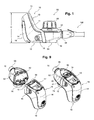
- the inhalator as shown in Figure 1 comprises a controller unit 10 and an aerosol generator unit 50 which are connected to each other. Further, a mouthpiece 120 is provided.
- the controller unit 10 has a housing (the first housing) 11.
- the housing has at its lower end a base 12 for supporting the inhalator on a horizontal surface such as a desk.
- a base 12 for supporting the inhalator on a horizontal surface such as a desk.
- an ON/OFF button 13 Integrated into the housing 11 is an ON/OFF button 13 and a battery compartment lid 14 that is removable from the housing 11 for exchanging batteries.
- a USB socket 15 is provided at one side of the housing 11, which may be used for connection to a power supply and/or charging the batteries in the battery compartment and/or for connection of the inhalator to a personal computer.
- a top 16 is defined opposite to the base 12, wherein the total height H of the inhalator is defined between the base 12 and the top 16.
- the height H of the inhalator preferably resides between 20 and 120 mm, preferably between 40 and 100 mm.
- the inhalator is preferably not higher than 150 mm, more preferably not higher than 120 mm, and most preferably not higher than 100 mm.
- the controller unit 10 further has a front 17 (see Figure 7 ) and a back 18.
- the battery compartment lid 14 is located at the back 18.
- a socket 19 is provided at the front 17 of the controller unit 10 as best visible from Figure 7 .
- the socket comprises a circumferential wall 20 which in the present embodiment forms a rectangular space. However, other cross-sectional shapes are conceivable such as circular, oval, etc.
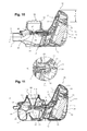
- a circuit board 21 extends from the controller housing 11 into the rectangular space (see Figure 11b ).
- the circuit board 21 has opposite sides 22 and 23 on each of which there are provided conductive paths (not visible in the drawings).
- the circuit board 21 is connected to a controller circuit board (controller) 24, preferably also by means of a plug and socket connection 25.
- the circuit board 24 within the controller housing 11 is oriented vertically, that means that it extends from the base 12 to the top 16 and it is rather directed to a vertical line than to a horizontal line meaning that it is angled within a range of 45° and 90° to a horizontal axis.
- the controller housing 11 has a portion 35 containing a portion of the controller circuit board 24 that resides above the aerosol generator as described later.
- a switch 26 is located on the circuit board below the bottom 15. Batteries 29 in the battery compartment 28 are connected to battery contacts 30 which again are contacted to the controller circuit board 24 by mere contact of elastic contacts at the position 31.
- the controller circuit board 24 is only secured to the controller housing 11 by one screw 32 wherein a conductive path of the controller circuit board 24 is electrical contact with the battery contact 30 at the position 31 so that no complicated assembly is required.
- the circuit board 21 is connected to the socket circuit board 24 by plug socket connection 25, the socket circuit board being fixed in the controller housing 11. Also in this case, no complicated assembly is required.
- the batteries 29, disposed in the battery compartment 28, are located closer to the base 12 than to the top 16, that is the contacts 30 contacting the batteries 29 are located so that the batteries 29 are located closer to the base 12 than to the top 16 if inserted into the battery compartment 28.
- a protrusion 33 of a latch 34 is integrally formed with the controller housing 11. This latch 34 is described in more detail below and is for connection of the controller unit 10 to the aerosol generator unit 50 or the cleaning unit 100.
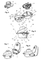
- the aerosol generator unit 50 has an aerosol generator housing (second housing) 51 which is separated into a first housing part 52 and a second housing part 53.
- the aerosol generator housing 51 comprises a bottom 54.
- a top 55 of the aerosol generator unit 50 opposite to the bottom 54 is formed by the lid 56.
- the first housing part 52 forms a nebulization chamber 57 into which the aerosol is introduced during operation of the aerosol generator.
- An outlet 58 having a center axis A is connected to the nebulization chamber 57.
- the outlet 58 is configured so that a mouthpiece 120, or a mask, or face mask, nasal prongs, or ventilator tube or endotracheal tube, or other equipment may be attached.
- the outlet 58 can be configured as a Luer connection.
- at least one rib 59 may be provided so that a tube may as well be connected.
- first housing part has at the bottom 54 a lug 60 of the latch 34 explained in more detail later.
- two protrusions 33 of a latch mechanism 34 are provided integrally with the first housing part 52 at a back 61 facing the front 17 of the controller unit 10.
- the outlet 58 is disposed at the front 62 opposite to the back 61.
- the housing 52 has an opening 63 at its top which is to be closed by the second housing part 53.
- the second housing part 53 comprises the aerosol generator 64 which is fixed in the second housing part 53 so as to be non-separable.
- the aerosol generator 64 comprises a membrane 65 which is vibratable by means of a piezoelectric actuator 80.
- the membrane 65 has a plurality of minute apertures (not visible in the drawings) and has a first side 67 and an opposite side 68.
- the membrane 65 is vibratable held between a lip seal 69 on the first side 67 and another O-ring 66 at the opposite side 68 as described in DE 102005006375 ( US 7,891,352 , or US 8,333,187 ) incorporated in its entirety by reference.
- Electrical contacts 71 are electrically connected to the piezoelectric actuator 80 and extend to the back 70 of the second housing part 53 at which electrical contacts are accessible.
- the elastic contacts 71 are formed facing each other with a space formed between them.
- the elastic electrical contacts 71 which are elastic in opposite directions extend into a space formed by a rectangular circumferential wall forming a plug 72.
- two parallel and symmetrically arranged electrical elastic contacts 71 are located at on side of the space (circumferential wall) and another two parallel and symmetrically arranged electrical elastic contacts 71 are located at on opposite side of the space (circumferential wall).
- a first electrical contact 71 at a first side and a second electrical contact 71 at the opposite second side form a first pair to be contacted to conductive paths on respective sides 22 and 23 of the socket circuit board 21 in a first orientation.
- the second housing part 53 has a boss 74 with an outer thread 75 forming the fluid container 76 which is closed at its lower end by the upper side 67 of the membrane 65.
- the boss has an opening 77 at its upper end into which a fluid to be nebulized may be filled.
- the opening 77 may be closed by means of the lid 56, which has an inner thread 78 to be screwed on the outer thread 75 of the boss 74.
- the second housing part 53 has at its back 70 two lugs 60 of latches 34 as described later in more detail.
- two openings 79 are formed in the second housing part 53 which serve as vents during inhalation, wherein air is drawn in through the opening 79 into the mixing chamber (nebulization chamber) 57 on its way to the outlet 58.
- one-way valves preferably flap valves, are disposed in the opening 79 so as to allow a flow of air from the outside to the inside only.
- the outlet 58 has a center axis A parallel to the membrane 65 (parallel extension of the membrane has been visualized by the broken line B in Figure 10 ) and is positioned closer to the bottom 54, and in a state connected to the controller unit 10, the base 12, than the membrane 65.
- the cleaning unit 100 has a cleaning unit housing (third housing) 101 comprising a first housing part 102 and a second housing part 103.
- the first housing part 102 is considered as the lower housing part and has a bottom 104, a front 105 directed in the connection state toward the controller unit 10 and a back 106 at an opposite side. Protrusions 33 of a latch 34 are provided on opposite side walls 107 of the first housing part 102.
- the first housing part 102 defines a receiving section 108 which is configured to receive the second housing part 53 of the aerosol generator unit 50.
- a centering boss 109 is disposed at the bottom of the receiving section 108 for centering the fluid container 76 and particularly its boss 74 within the receiving section 106 (see Figure 11a ).
- a spout 110 is disposed at the front 105 of the first housing part 102.
- the second housing part 103 is hinged to the first housing part 102 at the back 106 so that the second housing part 103 may be rotated about an axis 111 as indicated by the dotted line 112 in Figure 6 to provide access to the receiving section 108.
- Lugs 60 of a latch 34 are provided at side walls 113 of the second housing part 103.
- the second housing part 103 comprises a funnel-shaped fluid reservoir 114 with an opening 115 at the top of the second housing part 103.
- the funnel-shaped fluid reservoir 114 has a lip seal 116 at its lower end for sealing against the membrane 65 of the aerosol generator unit 50.
- latch 34 used at several locations is explained with reference to the latch 34 used for the cleaning unit 100 as shown in Figures 5 and 6 . This explanation, however, also applies to the other latches 34 used at other positions.
- Each latch 34 comprises a lug 60 which is integrally formed with the corresponding part, here the second housing part 103.
- the lug 60 extends away from the housing part 103.
- the lug 60 has a cutout 131.
- An area at that side of the cutout 131 facing away from the connection to the second housing part 103 is bent away, that is towards the outside to form a gripping part 133.
- a flexible area 132 which extends a certain distance D from the connection of the lug 60 to the second housing part 103 towards the cutout 131.
- the lug 60 is flexible in this flexible area 32 and may be bent towards and away from the second housing part 103. This bending is partially plastic deformation so that the lug 60 to certain extent will remain in its bent position rather than springing back to its original position.
- the latch 34 comprises a protrusion 33 which is integrally formed with the first housing part 102, particularly at its side wall 107.
- the first housing part 103 In order to close the latch 34, one would tilt the first housing part 103 about the axis 111 closing the first and second housing part 102 and 103.
- the lugs 60 at the sides override the protrusions 33.
- the cutouts 131 engage with the protrusions 33 and the lug 60 remains in this position being bent towards the second housing part 102.
- the user receives an audible signal such as click and also visibly recognizes a secure connection, because he has to actively move the lug 60 into engagement the protrusion 33 in contrast to conventional snap mechanisms in which the latches automatically snap into engagement.
- guiding elements may be formed as one example by a longitudinal protrusion 40 at one of the housings and a longitudinal recess 41 at the other of the housings.
- the protrusion 40 engages with the recess 41 and translationally guides the housings until the housings are fully connected.
- the housings may be locked by means of the latch 34 as described earlier.
- two such protrusions 40/ recesses 41 are provided in parallel to prevent tilting of one housing relative to the other housing during the connection process.
- other numbers and configurations of guiding elements are conceivable as well.
- a portion of the housing 11 of the controller unit 10 that contains a portion of the controller, namely the controller circuit board 24 that is referenced to as the portion 35 extends beyond the aerosol generator, here the membrane 65.
- the portion 35 is located further away from the base 12 or the bottom 54 respectively than the aerosol generator, i.e. the membrane 65.
- at least a part of this portion extends beyond the top 55 of the aerosol generator unit 50 and particularly the lid 56.
- the battery compartment 28 comprising the batteries 29 is configured so that the batteries 29 are positioned closer to the base 12 than to the top 16.
- controller housing 11 and particularly the portion 35 as part thereof form a grip for holding the inhalator during inhalation. Even though this configuration at first glance appears not very ergonomic, it has been proven very comfortable and convenient to use, particularly by one hand only.
- the controller unit 10 and the aerosol generator unit 50 are connected without the use of a cable.
- the aerosol generator unit 50 shown in Figure 2 one merely needs to connect the plug 72 to the socket 19.
- this is achieved in that the circuit board 21 with the not shown conductive paths on the opposite sides 22 and 23 is inserted into the aforesaid space between the elastic contacts 71 of the plug 70 of the aerosol generator.
- the aerosol generator unit 50 is merely translated towards the controller unit 10, whereby the plug 70 and the socket 19 mate, that engage and electrically connect.
- the inhalator may be placed on a horizontal surface with its base 12 facing downward.
- the inhalator is ready for use, wherein the liquid applies at the side 67 of the membrane 65.
- the aerosol generator unit 10 is configured with a two-part housing having the first and second housing parts 52 and 53.
- the lugs 60 shown in Figure 2 are gripped at the gripping portion 133 and flexed in its flexible area 132 away from the back 61 of the first housing part 52.
- the cutouts 130 disengaged with the protrusions 33 and the second housing part 53 may be removed from the first housing part 52 as shown in Figure 3 .
- the lid 56 is removed from the boss 74.
- the aerosol generator 64 including the membrane 65 is preferably fixed to the second housing part 53 and may not be removed from this part 53. Having removed the second housing part 53 and the lid 56 as shown in Figure 5 , the second housing part 53 is rotated by 180°.
- the second housing part 53 together with the aerosol generator 64, particularly the membrane 65 is inserted into the receiving section 108 of the cleaning unit 100, the centering boss 109 and the fluid container 76, particularly the boss 74 engage for centering the aerosol generator 64 and particularly the second housing part 53 within the receiving section.
- the plug 72 is rotated by 180°.
- the cleaning unit may be closed by rotating the second housing part 103 relative to the first housing part 102 and engaging the lugs 60 and particularly their cutouts 130 with the protrusions 33 at the sides 107 of the first housing part 102.
- the cleaning unit is closed and may be connected to the controller unit.
- the cleaning unit 100 is as well translated towards the controller unit 10, whereby the plug 70 and the socket 19 electrically insert into each other to obtain an electrical connection between the elastic contacts 71 and the circuit board 21.
- the wall 73 inserts into the wall 20.
- the lug 60 of the cleaning unit 100 is engaged with the protrusion 33 of the controller unit as described with respect to the aerosol generator unit in Figure 9 .
- the cleaning unit 100 and the controller unit 11 are securely fixed to each other. Even though, the aerosol generator and, hence, the plug 70 have been rotated by 180° as shown in Figure 5 and because of the configuration of the plug 70 and the socket 19 is still possible to mate the plug 70 and the socket 19 in the same manner, namely a translational movement. Thus, a cable can be omitted and operation of the inhalator be facilitated for a user.
- a cleaning solution is introduced through the opening 115 into the funnel-shaped fluid reservoir 114 applying at the side 68 of the membrane 65.
- the aerosol generator is operated by pressing the button 15.
- the fluid to be nebulized as well as the cleaning solution is fed to the membrane 65 by gravitational force.
- the cleaning solution is collected as shown in Figure 11 within the first housing part 102 and may after cleaning be poured out through the spout 110.
Landscapes
- Health & Medical Sciences (AREA)
- Engineering & Computer Science (AREA)
- Animal Behavior & Ethology (AREA)
- Anesthesiology (AREA)
- Biomedical Technology (AREA)
- Heart & Thoracic Surgery (AREA)
- Hematology (AREA)
- Life Sciences & Earth Sciences (AREA)
- General Health & Medical Sciences (AREA)
- Public Health (AREA)
- Veterinary Medicine (AREA)
- Pulmonology (AREA)
- Bioinformatics & Cheminformatics (AREA)
- Emergency Medicine (AREA)
- Containers And Packaging Bodies Having A Special Means To Remove Contents (AREA)
Priority Applications (10)
| Application Number | Priority Date | Filing Date | Title |
|---|---|---|---|
| EP14156519.2A EP2910268A1 (de) | 2014-02-25 | 2014-02-25 | Inhalator und Inhalatorsatz |
| ES15707590T ES2752700T3 (es) | 2014-02-25 | 2015-02-25 | Inhalador y conjunto de inhalador |
| PCT/EP2015/053930 WO2015128375A1 (en) | 2014-02-25 | 2015-02-25 | Inhalator and inhalator set |
| JP2016553852A JP2017506540A (ja) | 2014-02-25 | 2015-02-25 | 吸入器および吸入器セット |
| US15/118,986 US10493217B2 (en) | 2014-02-25 | 2015-02-25 | Inhalator and inhalator set |
| CN201580010377.8A CN106102808B (zh) | 2014-02-25 | 2015-02-25 | 吸入器和吸入器组 |
| EP15707590.4A EP3110482B1 (de) | 2014-02-25 | 2015-02-25 | Inhalator und inhalatorsatz |
| ES19190220T ES2943662T3 (es) | 2014-02-25 | 2015-02-25 | Inhalador |
| EP19190220.4A EP3586896B1 (de) | 2014-02-25 | 2015-02-25 | Inhalator |
| US16/668,054 US11419993B2 (en) | 2014-02-25 | 2019-10-30 | Inhalator and inhalator set |
Applications Claiming Priority (1)
| Application Number | Priority Date | Filing Date | Title |
|---|---|---|---|
| EP14156519.2A EP2910268A1 (de) | 2014-02-25 | 2014-02-25 | Inhalator und Inhalatorsatz |
Publications (1)
| Publication Number | Publication Date |
|---|---|
| EP2910268A1 true EP2910268A1 (de) | 2015-08-26 |
Family
ID=50156639
Family Applications (3)
| Application Number | Title | Priority Date | Filing Date |
|---|---|---|---|
| EP14156519.2A Withdrawn EP2910268A1 (de) | 2014-02-25 | 2014-02-25 | Inhalator und Inhalatorsatz |
| EP15707590.4A Active EP3110482B1 (de) | 2014-02-25 | 2015-02-25 | Inhalator und inhalatorsatz |
| EP19190220.4A Active EP3586896B1 (de) | 2014-02-25 | 2015-02-25 | Inhalator |
Family Applications After (2)
| Application Number | Title | Priority Date | Filing Date |
|---|---|---|---|
| EP15707590.4A Active EP3110482B1 (de) | 2014-02-25 | 2015-02-25 | Inhalator und inhalatorsatz |
| EP19190220.4A Active EP3586896B1 (de) | 2014-02-25 | 2015-02-25 | Inhalator |
Country Status (6)
| Country | Link |
|---|---|
| US (2) | US10493217B2 (de) |
| EP (3) | EP2910268A1 (de) |
| JP (1) | JP2017506540A (de) |
| CN (1) | CN106102808B (de) |
| ES (2) | ES2752700T3 (de) |
| WO (1) | WO2015128375A1 (de) |
Cited By (4)
| Publication number | Priority date | Publication date | Assignee | Title |
|---|---|---|---|---|
| EP2957348A1 (de) * | 2014-06-20 | 2015-12-23 | Taiwan Puritic Corp. | Zerstäubungsanordnung und damit hergestellter zerstäuber |
| WO2017133818A1 (de) * | 2016-02-03 | 2017-08-10 | H&B Electronic GmBH & Co. KG | Injektionsvorrichtung |
| EP3556475A1 (de) | 2018-04-20 | 2019-10-23 | PARI GmbH Spezialisten für effektive Inhalation | Steuergerät für einen aerosolgenerator |
| CN110430910A (zh) * | 2017-03-20 | 2019-11-08 | 维克多瑞传送设备有限公司 | 用于清洁雾化器的膜的容器 |
Families Citing this family (30)
| Publication number | Priority date | Publication date | Assignee | Title |
|---|---|---|---|---|
| EP2910268A1 (de) | 2014-02-25 | 2015-08-26 | PARI Pharma GmbH | Inhalator und Inhalatorsatz |
| AU2016205562A1 (en) * | 2015-01-09 | 2017-06-15 | Adherium (Nz) Limited | Monitor for a medicament inhaler |
| WO2017192773A1 (en) | 2016-05-03 | 2017-11-09 | Pneuma Respiratory, Inc. | Methods for treatment of pulmonary lung diseases with improved therapeutic efficacy and improved dose efficiency |
| KR102295739B1 (ko) | 2016-05-03 | 2021-08-30 | 뉴마 레스퍼러토리 인코포레이티드 | 유체들의 폐기관계로의 전달을 위한 액적 전달 디바이스 및 사용 방법 |
| EP4624054A3 (de) * | 2016-05-03 | 2025-11-19 | Pneuma Respiratory, Inc. | Verfahren zur erzeugung und abgabe von tröpfchen an das lungensystem unter verwendung einer tröpfchenabgabevorrichtung |
| WO2017192782A1 (en) | 2016-05-03 | 2017-11-09 | Pneuma Respiratory, Inc. | Systems and methods comprising a droplet delivery device and a breathing assist device for therapeutic treatment |
| US11285274B2 (en) | 2016-05-03 | 2022-03-29 | Pneuma Respiratory, Inc. | Methods for the systemic delivery of therapeutic agents to the pulmonary system using a droplet delivery device |
| EP3323454A1 (de) * | 2016-11-16 | 2018-05-23 | Yu-Kang Huang | Tragbarer gitterzerstäuber |
| ES2975768T3 (es) | 2017-03-20 | 2024-07-15 | Vectura Delivery Devices Ltd | Método y recipiente para limpiar la membrana de un nebulizador |
| CN107041986A (zh) * | 2017-04-17 | 2017-08-15 | 苏州新劢德医疗器械科技有限公司 | 粉末药品吸入器 |
| WO2018213834A1 (en) | 2017-05-19 | 2018-11-22 | Pneuma Respiratory, Inc. | Dry powder delivery device and methods of use |
| CN118203735A (zh) | 2017-10-04 | 2024-06-18 | 精呼吸股份有限公司 | 电子呼吸致动式直线型液滴输送装置及其使用方法 |
| EP3697481B1 (de) | 2017-10-17 | 2024-05-22 | Pneuma Respiratory, Inc. | Nasale arzneimittelabgabevorrichtung und verwendungsverfahren |
| CA3082192A1 (en) | 2017-11-08 | 2019-05-16 | Pneuma Respiratory, Inc. | Electronic breath actuated in-line droplet delivery device with small volume ampoule and methods of use |
| US20210106772A1 (en) * | 2018-04-02 | 2021-04-15 | Pneuma Respiratory, Inc. | Handheld digital nebulizer device and methods of use |
| US12691236B2 (en) | 2019-05-09 | 2026-07-28 | Pneuma Respiratory, Inc. | Ultrasonic breath actuated respiratory droplet delivery device and methods of use |
| CN114206421A (zh) | 2019-06-27 | 2022-03-18 | 精呼吸股份有限公司 | 小液滴经由电子呼吸致动液滴输送装置到呼吸系统的输送 |
| USD899584S1 (en) * | 2019-08-13 | 2020-10-20 | Convexity Scientific Inc. | Reservoir piezo disk assembly for a nebulizer |
| US20210228824A1 (en) * | 2020-01-29 | 2021-07-29 | Aerami Therapeutics, Inc. | Wicking cap and methods |
| JP2023520542A (ja) | 2020-04-01 | 2023-05-17 | ユニオン・セラピューティクス・アー/エス | 治療薬 |
| CN115701983A (zh) | 2020-04-01 | 2023-02-14 | 联合治疗股份公司 | 配制品 |
| US11045434B1 (en) | 2020-04-01 | 2021-06-29 | UNION therapeutics A/S | Niclosamide formulations for treating disease |
| DE102020122672A1 (de) * | 2020-08-31 | 2022-03-03 | Hamilton Medical Ag | Beatmungsvorrichtung mit an einer inneren Funktionsanordnung befestigter Eingabe/Ausgabevorrichtung |
| DE102020122671A1 (de) * | 2020-08-31 | 2022-03-03 | Hamilton Medical Ag | Beatmungsvorrichtung mit an einer inneren Funktionsanordnung verriegelter Eingabe/Ausgabevorrichtung |
| WO2022271848A1 (en) | 2021-06-22 | 2022-12-29 | Pneuma Respiratory, Inc. | Droplet delivery device with push ejection |
| US20250144324A1 (en) * | 2022-06-01 | 2025-05-08 | Neucen Biomed Co., Ltd. | Cns inhaler and operating method thereof |
| WO2023231367A1 (en) * | 2022-06-01 | 2023-12-07 | Neucen Biomed Co., Ltd. | Respiratory system inhaler and operating method thereof |
| CN119768202A (zh) | 2022-07-18 | 2025-04-04 | 精呼吸股份有限公司 | 小步长高分辨率气溶胶生成系统及方法 |
| EP4464351A1 (de) * | 2023-05-15 | 2024-11-20 | PARI Pharma GmbH | Inhalationstherapievorrichtung |
| WO2026008676A1 (en) * | 2024-07-03 | 2026-01-08 | Activoris Medizintechnik Gmbh | Aerosol generator component |
Citations (12)
| Publication number | Priority date | Publication date | Assignee | Title |
|---|---|---|---|---|
| US4300546A (en) * | 1978-11-15 | 1981-11-17 | Carl Heyer Gmbh Inhalationstechnik | Hand-held atomizer especially for dispensing inhalation-administered medicaments |
| US20020020408A1 (en) * | 2000-05-25 | 2002-02-21 | Invivotech, Inc. | Inhalation medicament delivery device |
| US20030000520A1 (en) * | 1995-04-05 | 2003-01-02 | Aerogen, Inc. | Liquid dispensing apparatus and methods |
| WO2004041335A1 (de) * | 2002-11-07 | 2004-05-21 | Pari GmbH Spezialisten für effektive Inhalation | Inhalationstherapievorrichtung |
| JP2005278742A (ja) * | 2004-03-29 | 2005-10-13 | A & D Co Ltd | 霧放出器 |
| DE102005006375A1 (de) | 2005-02-11 | 2006-08-24 | Pari GmbH Spezialisten für effektive Inhalation | Aerosolerzeugungsvorrichtung für Inhalationstherapiegeräte |
| US20070062520A1 (en) * | 2005-09-13 | 2007-03-22 | Canon Kabushiki Kaisha | Liquid medicine ejection device |
| EP1852896A1 (de) | 2006-05-05 | 2007-11-07 | Kinik Company | Diamantsubstrat und Verfahren zu dessen Herstellung |
| EP1875936B1 (de) | 2006-07-04 | 2009-11-18 | PARI Pharma GmbH | Verfahren und Vorrichtung ausgelegt für die Reinigung der Verneblermembran in einem Inhalationstherapiegerät |
| US20110108025A1 (en) | 2008-04-04 | 2011-05-12 | Nektar Therapeutics | Aerosolization device |
| WO2011088070A1 (en) * | 2010-01-12 | 2011-07-21 | Dance Pharmaceuticals Inc. | Preservative-free single dose inhaler systems |
| WO2011089485A1 (en) * | 2010-01-19 | 2011-07-28 | Koninklijke Philips Electronics N.V. | Nebulizing drug delivery device having an improved user interface and a method of manufacturing the same |
Family Cites Families (25)
| Publication number | Priority date | Publication date | Assignee | Title |
|---|---|---|---|---|
| DE3429389C1 (de) | 1984-08-09 | 1986-03-13 | Brugger, Inge, geb. Ritzau, 8130 Starnberg | Inhalator |
| CN85106740A (zh) * | 1985-09-06 | 1987-03-25 | 英格·布鲁格·伯恩·里茨奥 | 吸入器 |
| US4922901A (en) * | 1988-09-08 | 1990-05-08 | R. J. Reynolds Tobacco Company | Drug delivery articles utilizing electrical energy |
| US6540154B1 (en) * | 1991-04-24 | 2003-04-01 | Aerogen, Inc. | Systems and methods for controlling fluid feed to an aerosol generator |
| US5452711A (en) * | 1992-12-24 | 1995-09-26 | Exar Corporation | Small form factor atomizer |
| US5758637A (en) * | 1995-08-31 | 1998-06-02 | Aerogen, Inc. | Liquid dispensing apparatus and methods |
| US6205999B1 (en) * | 1995-04-05 | 2001-03-27 | Aerogen, Inc. | Methods and apparatus for storing chemical compounds in a portable inhaler |
| US6550472B2 (en) * | 2001-03-16 | 2003-04-22 | Aerogen, Inc. | Devices and methods for nebulizing fluids using flow directors |
| US6684880B2 (en) * | 2001-12-04 | 2004-02-03 | Hewlett-Packard Development Company, L.P. | Applicator for dispensing bioactive compositions and methods for using the same |
| AU2003235678A1 (en) * | 2002-01-15 | 2003-07-30 | Aerogen, Inc. | Systems and methods for clearing aerosols from the effective anatomic dead space |
| DE10203079A1 (de) * | 2002-01-28 | 2003-08-21 | Pari Gmbh | Atemflussmessvorrichtung |
| DE10345950A1 (de) * | 2003-10-02 | 2005-05-19 | Pari GmbH Spezialisten für effektive Inhalation | Inhalationstherapievorrichtung mit Ventil |
| DE102004006450B4 (de) * | 2004-02-05 | 2012-09-27 | Ing. Erich Pfeiffer Gmbh | Dosiervorrichtung |
| US8056557B2 (en) | 2005-03-09 | 2011-11-15 | Ric Investments, Llc | Nebulizing drug delivery device with barrier |
| JP5207679B2 (ja) * | 2006-08-01 | 2013-06-12 | キヤノン株式会社 | 薬剤吐出装置 |
| US20080110453A1 (en) * | 2006-11-15 | 2008-05-15 | Delphi Technologies Inc. | Nebulizer and methods for controlling the nebulizer |
| JP5328256B2 (ja) * | 2008-08-04 | 2013-10-30 | キヤノン株式会社 | 吸入装置 |
| AT507187B1 (de) * | 2008-10-23 | 2010-03-15 | Helmut Dr Buchberger | Inhalator |
| JP5267245B2 (ja) * | 2009-03-17 | 2013-08-21 | オムロンヘルスケア株式会社 | ネブライザ、および、ネブライザに着脱可能な機能ユニット |
| AT511344B1 (de) * | 2011-10-21 | 2012-11-15 | Helmut Dr Buchberger | Inhalatorkomponente |
| EP2724741B1 (de) * | 2012-10-26 | 2017-06-14 | Vectura GmbH | Inhalationsvorrichtung zur Verwendung in einer Inhalationstherapie |
| EP2679265A1 (de) * | 2012-06-28 | 2014-01-01 | Pari GmbH | Kunststoffscharnier |
| CN202802428U (zh) * | 2012-09-20 | 2013-03-20 | 湖北鑫六通医疗科技有限公司 | 鼻腔吸入器 |
| ITMI20121923A1 (it) * | 2012-11-12 | 2014-05-13 | Flaem Nuova Spa | Apparecchio nebulizzatore portatile ad uso medicale, con accesso facilitato al gruppo mesh |
| EP2910268A1 (de) | 2014-02-25 | 2015-08-26 | PARI Pharma GmbH | Inhalator und Inhalatorsatz |
-
2014
- 2014-02-25 EP EP14156519.2A patent/EP2910268A1/de not_active Withdrawn
-
2015
- 2015-02-25 JP JP2016553852A patent/JP2017506540A/ja active Pending
- 2015-02-25 EP EP15707590.4A patent/EP3110482B1/de active Active
- 2015-02-25 ES ES15707590T patent/ES2752700T3/es active Active
- 2015-02-25 EP EP19190220.4A patent/EP3586896B1/de active Active
- 2015-02-25 US US15/118,986 patent/US10493217B2/en active Active
- 2015-02-25 CN CN201580010377.8A patent/CN106102808B/zh active Active
- 2015-02-25 WO PCT/EP2015/053930 patent/WO2015128375A1/en not_active Ceased
- 2015-02-25 ES ES19190220T patent/ES2943662T3/es active Active
-
2019
- 2019-10-30 US US16/668,054 patent/US11419993B2/en active Active
Patent Citations (14)
| Publication number | Priority date | Publication date | Assignee | Title |
|---|---|---|---|---|
| US4300546A (en) * | 1978-11-15 | 1981-11-17 | Carl Heyer Gmbh Inhalationstechnik | Hand-held atomizer especially for dispensing inhalation-administered medicaments |
| US20030000520A1 (en) * | 1995-04-05 | 2003-01-02 | Aerogen, Inc. | Liquid dispensing apparatus and methods |
| US20020020408A1 (en) * | 2000-05-25 | 2002-02-21 | Invivotech, Inc. | Inhalation medicament delivery device |
| WO2004041335A1 (de) * | 2002-11-07 | 2004-05-21 | Pari GmbH Spezialisten für effektive Inhalation | Inhalationstherapievorrichtung |
| JP2005278742A (ja) * | 2004-03-29 | 2005-10-13 | A & D Co Ltd | 霧放出器 |
| US7891352B2 (en) | 2005-02-11 | 2011-02-22 | Pari Pharma Gmbh | Aerosol generating means for inhalation therapy devices |
| DE102005006375A1 (de) | 2005-02-11 | 2006-08-24 | Pari GmbH Spezialisten für effektive Inhalation | Aerosolerzeugungsvorrichtung für Inhalationstherapiegeräte |
| US8333187B2 (en) | 2005-02-11 | 2012-12-18 | Pari Pharma Gmbh | Aerosol generating means for inhalation therapy devices |
| US20070062520A1 (en) * | 2005-09-13 | 2007-03-22 | Canon Kabushiki Kaisha | Liquid medicine ejection device |
| EP1852896A1 (de) | 2006-05-05 | 2007-11-07 | Kinik Company | Diamantsubstrat und Verfahren zu dessen Herstellung |
| EP1875936B1 (de) | 2006-07-04 | 2009-11-18 | PARI Pharma GmbH | Verfahren und Vorrichtung ausgelegt für die Reinigung der Verneblermembran in einem Inhalationstherapiegerät |
| US20110108025A1 (en) | 2008-04-04 | 2011-05-12 | Nektar Therapeutics | Aerosolization device |
| WO2011088070A1 (en) * | 2010-01-12 | 2011-07-21 | Dance Pharmaceuticals Inc. | Preservative-free single dose inhaler systems |
| WO2011089485A1 (en) * | 2010-01-19 | 2011-07-28 | Koninklijke Philips Electronics N.V. | Nebulizing drug delivery device having an improved user interface and a method of manufacturing the same |
Cited By (6)
| Publication number | Priority date | Publication date | Assignee | Title |
|---|---|---|---|---|
| EP2957348A1 (de) * | 2014-06-20 | 2015-12-23 | Taiwan Puritic Corp. | Zerstäubungsanordnung und damit hergestellter zerstäuber |
| WO2017133818A1 (de) * | 2016-02-03 | 2017-08-10 | H&B Electronic GmBH & Co. KG | Injektionsvorrichtung |
| CN110430910A (zh) * | 2017-03-20 | 2019-11-08 | 维克多瑞传送设备有限公司 | 用于清洁雾化器的膜的容器 |
| EP3556475A1 (de) | 2018-04-20 | 2019-10-23 | PARI GmbH Spezialisten für effektive Inhalation | Steuergerät für einen aerosolgenerator |
| WO2019202085A1 (en) | 2018-04-20 | 2019-10-24 | Pari Pharma Gmbh | Controller for an aerosol generator |
| US11992603B2 (en) | 2018-04-20 | 2024-05-28 | Pari Pharma Gmbh | Controller for an aerosol generator |
Also Published As
| Publication number | Publication date |
|---|---|
| JP2017506540A (ja) | 2017-03-09 |
| US20200155772A1 (en) | 2020-05-21 |
| US20160354557A1 (en) | 2016-12-08 |
| ES2943662T3 (es) | 2023-06-15 |
| ES2752700T3 (es) | 2020-04-06 |
| US10493217B2 (en) | 2019-12-03 |
| EP3586896A1 (de) | 2020-01-01 |
| CN106102808A (zh) | 2016-11-09 |
| CN106102808B (zh) | 2021-08-17 |
| WO2015128375A1 (en) | 2015-09-03 |
| EP3110482A1 (de) | 2017-01-04 |
| EP3586896B1 (de) | 2023-04-05 |
| EP3110482B1 (de) | 2019-09-25 |
| US11419993B2 (en) | 2022-08-23 |
Similar Documents
| Publication | Publication Date | Title |
|---|---|---|
| US11419993B2 (en) | Inhalator and inhalator set | |
| EP3432958B2 (de) | Mechanischer verbinder für elektronisches dampfversorgungssystem | |
| EP3298913B1 (de) | Gehäuse für eine elektronische rauchvorrichtung | |
| US11612703B2 (en) | Push connector for vape cartridges | |
| EP3082926B1 (de) | Befeuchtungssystemverbindungen | |
| JP6434652B2 (ja) | 電子タバコ | |
| CN108465147B (zh) | 用于加湿系统的连接 | |
| US10105511B2 (en) | Respiratory humidifier | |
| CN106659234A (zh) | 用于电子烟的再充电包装 | |
| KR20200000981A (ko) | 전기가열식 에어로졸 발생기 | |
| KR20170000818U (ko) | 전자담배용 드립팁 및 이를 구비하는 전자담배 | |
| JP2005287596A (ja) | 呼吸用気体供給装置 | |
| ITUB20153897A1 (it) | Dispositivo nebulizzatore portatile per fluidi medicali perfezionato | |
| CN216136505U (zh) | 一种口腔喷雾器 | |
| EP4331406A1 (de) | Zerstäubungsvorrichtung und zerstäubungsvorrichtung | |
| CN216136504U (zh) | 一种储液装置及口腔喷雾器 | |
| KR20190036833A (ko) | 약액흡입기 장치 | |
| JPH10220364A (ja) | 液体滴下装置 |
Legal Events
| Date | Code | Title | Description |
|---|---|---|---|
| PUAI | Public reference made under article 153(3) epc to a published international application that has entered the european phase |
Free format text: ORIGINAL CODE: 0009012 |
|
| AK | Designated contracting states |
Kind code of ref document: A1 Designated state(s): AL AT BE BG CH CY CZ DE DK EE ES FI FR GB GR HR HU IE IS IT LI LT LU LV MC MK MT NL NO PL PT RO RS SE SI SK SM TR |
|
| AX | Request for extension of the european patent |
Extension state: BA ME |
|
| STAA | Information on the status of an ep patent application or granted ep patent |
Free format text: STATUS: THE APPLICATION IS DEEMED TO BE WITHDRAWN |
|
| 18D | Application deemed to be withdrawn |
Effective date: 20160227 |