EP2910367A1 - Appareil d'estampage de type estampage flash pour pains de savon, pour la production de savons de toilette, savons de blanchisserie ou similaires - Google Patents
Appareil d'estampage de type estampage flash pour pains de savon, pour la production de savons de toilette, savons de blanchisserie ou similaires Download PDFInfo
- Publication number
- EP2910367A1 EP2910367A1 EP15152895.7A EP15152895A EP2910367A1 EP 2910367 A1 EP2910367 A1 EP 2910367A1 EP 15152895 A EP15152895 A EP 15152895A EP 2910367 A1 EP2910367 A1 EP 2910367A1
- Authority
- EP
- European Patent Office
- Prior art keywords
- formation cavity
- cavity parts
- die part
- parts
- formation
- Prior art date
- Legal status (The legal status is an assumption and is not a legal conclusion. Google has not performed a legal analysis and makes no representation as to the accuracy of the status listed.)
- Withdrawn
Links
- 239000000344 soap Substances 0.000 title claims abstract description 94
- 238000004519 manufacturing process Methods 0.000 title claims abstract description 8
- 230000015572 biosynthetic process Effects 0.000 claims abstract description 202
- 238000000605 extraction Methods 0.000 claims abstract description 79
- 230000008878 coupling Effects 0.000 claims abstract description 11
- 238000010168 coupling process Methods 0.000 claims abstract description 11
- 238000005859 coupling reaction Methods 0.000 claims abstract description 11
- 238000003780 insertion Methods 0.000 claims abstract description 5
- 230000037431 insertion Effects 0.000 claims abstract description 5
- 230000033001 locomotion Effects 0.000 claims description 16
- 230000009467 reduction Effects 0.000 claims description 3
- 230000000284 resting effect Effects 0.000 claims description 3
- 230000000875 corresponding effect Effects 0.000 description 49
- 238000001816 cooling Methods 0.000 description 14
- 230000009471 action Effects 0.000 description 4
- 230000007704 transition Effects 0.000 description 4
- 230000005540 biological transmission Effects 0.000 description 3
- 239000012809 cooling fluid Substances 0.000 description 3
- 239000000110 cooling liquid Substances 0.000 description 3
- 230000013011 mating Effects 0.000 description 3
- 238000000926 separation method Methods 0.000 description 3
- 241000252254 Catostomidae Species 0.000 description 2
- 230000008901 benefit Effects 0.000 description 2
- 238000000034 method Methods 0.000 description 2
- 238000012986 modification Methods 0.000 description 2
- 230000004048 modification Effects 0.000 description 2
- 230000004075 alteration Effects 0.000 description 1
- 238000013459 approach Methods 0.000 description 1
- 230000002596 correlated effect Effects 0.000 description 1
- 239000012530 fluid Substances 0.000 description 1
- 230000000670 limiting effect Effects 0.000 description 1
- 238000012423 maintenance Methods 0.000 description 1
- 239000000463 material Substances 0.000 description 1
- 238000004513 sizing Methods 0.000 description 1
Images





Classifications
-
- B—PERFORMING OPERATIONS; TRANSPORTING
- B30—PRESSES
- B30B—PRESSES IN GENERAL
- B30B11/00—Presses specially adapted for forming shaped articles from material in particulate or plastic state, e.g. briquetting presses, tabletting presses
- B30B11/02—Presses specially adapted for forming shaped articles from material in particulate or plastic state, e.g. briquetting presses, tabletting presses using a ram exerting pressure on the material in a moulding space
-
- B—PERFORMING OPERATIONS; TRANSPORTING
- B30—PRESSES
- B30B—PRESSES IN GENERAL
- B30B15/00—Details of, or accessories for, presses; Auxiliary measures in connection with pressing
- B30B15/0029—Details of, or accessories for, presses; Auxiliary measures in connection with pressing means for adjusting the space between the press slide and the press table, i.e. the shut height
Definitions
- the present invention relates to a stamping apparatus of the flash stamping type for soap bars, for the production of toiletry soaps, laundry soaps or the like.
- Apparatuses for performing stamping, of the flash stamping type, of soap bars to produce toiletry soaps, laundry soaps or the like are known. These apparatuses are composed generally of a first die part and a second die part, which can be mutually coupled.
- the first die part which can be fixed or can rotate about a horizontal axis, there is a plurality of first formation cavity parts, each of which is extended around a corresponding axis.
- the first formation cavity parts are arranged in the first die part in mutual alignment, i.e., with their axes arranged on a same central plane.
- These first formation cavity parts are open at their axial end or mouth that can face the second die part and are delimited, a the opposite axial end, by a bottom that is occupied partially by an extraction plug.
- the second die part there is correspondingly a plurality of second formation cavity parts, each of which is extended around a corresponding axis.
- the second formation cavity parts also are arranged in the second die part in mutual alignment, i.e., with their axes arranged on a same central plane.
- the second formation cavity parts are open at their axial end or mouth that can face the first die part and are delimited, at the opposite axial end, by a bottom that is occupied partially by an extraction plug.
- the second die part in apparatuses of this kind, can move with an alternating movement for approach to the first die part, so as to close the first formation cavity parts by way of the coupling with the second formation cavity parts, stamping a soap bar interposed beforehand between the first die part and the second die part, or for spacing from the first die part, so as to allow the extraction and spacing of the stamped pieces of soap and the insertion, between the first die part and the second die part, of a new soap bar to be stamped.
- each one of the first formation cavity parts with a corresponding second formation cavity part defines a formation cavity for a piece of soap to be stamped.
- this formation cavity is constituted substantially completely by the first formation cavity part and therefore is defined substantially completely in the first die part.
- the stamped pieces of soap remain in the first die part and are removed and moved away by way of sucker-fitted grip and removal means.
- the action of these grip and removal means is assisted by the actuation of the extraction plugs provided in the bottom of the first formation cavity parts, which, being moved toward the open axial end of the corresponding first formation cavity part, push the pieces of soap to exit from the first formation cavity part, overcoming the friction of the pieces of soap against the walls of the first formation cavity part, thus facilitating the action of the sucker-fitted grip and removal means.
- the extraction plugs provided in the bottom of the second formation cavity parts have the function of facilitating separation, from the bottom of the second formation cavity parts, of the stamped pieces of soap when the second die part is moved away from the first die part.
- Stamping apparatuses of the flash stamping type with respect to other stamping apparatuses of the known type, such as for example "die box” stamping apparatuses, have the advantage of allowing high production rates and of not requiring precise sizing of the soap bar to be stamped, since in this type of apparatus the excess soap is evacuated automatically laterally to the formation cavities and is recovered to produce other soap bars to be stamped.
- the aim of the present invention is to meet this requirement, by providing a stamping apparatus of the flash stamping type for soap bars, for the production of toiletry soaps, laundry soaps or the like, in which it is possible to vary on command the volume of the formation cavities.
- an object of the invention is to provide an apparatus that allows to vary the volume of the formation cavities with high precision and rapidly.
- Another object of the invention is to provide an apparatus that can be derived from apparatuses of a known type with modifications that are simple to perform.
- a further object of the invention is to provide an apparatus that offers the greatest assurances of safety and reliability in use.
- a stamping apparatus of the flash stamping type for soap bars for the production of toiletry soaps, laundry soaps or the like, comprising a first die part, in which there is a plurality of first formation cavity parts, each of which is extended around a corresponding axis, and a second die part, in which there is correspondingly a plurality of second formation cavity parts, each extended around a corresponding axis, said second die part being movable on command toward said first die part, in order to close the formation cavity parts by means of the coaxial coupling of each one of said first formation cavity parts with the corresponding second formation cavity parts and stamp a bar of soap interposed between said first die part and said second die part, or away from said first die part, in order to open said formation cavity parts and allow the extraction of the stamped pieces of soap from said formation cavity parts and the insertion, between said die parts, of a new soap bar to be stamped, the coupling of each one of said first formation cavity
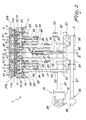
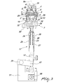
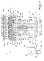
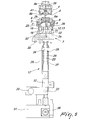
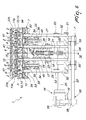
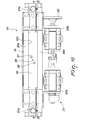
- the apparatus according to the invention designated generally in the two embodiments by the reference numerals 1, 61, comprises a first fixed or rotating die part 3, 62, of a known type and shown only partially for the sake of simplicity, and a second die part 4, 63 or alternated die part, which can be coupled to the first die part 3, 62.
- first formation cavity parts 2, 64 which are each extended around a corresponding axis 2a, 64a and are preferably mutually aligned, i.e., their axes 2a, 64a are arranged on a same central plane.
- These first formation cavity parts 2, 64 are open at an axial end thereof or mouth 2b, 64b, which is intended to face the second die part 4, 63.
- second formation cavity parts 8, 69 which are extended, so as to correspond to the first formation cavity parts 2, 64, each around a corresponding axis 8a, 69a and are preferably aligned with each other, i.e., their axes 8a, 69a are arranged on a same central plane.
- the second formation cavity parts 8, 69 are open at an axial end thereof or mouth 8b, 69b, which is intended to face the first die part 3, 62.
- the second die part 4, 63 can move on command, in a per se known manner, toward the first die part 3, 62 in order to close the formation cavity parts 2, 8, 64, 69 by means of the coaxial coupling the first formation cavity parts 2, 64 with the corresponding second formation cavity parts 8, 69 and thus stamp a bar of soap interposed between the first die part 3, 62 and the second die part 4, 63, or away from the first die part 3, 62 in order to open the formation cavity parts 2, 8, 64, 69 and allow the extraction of the stamped pieces of soap 6, 72 from the formation cavity parts 2, 8, 64, 69 and the insertion, between the first die part 3, 62 and the second die part 4, 63, of a new bar of soap to be stamped.
- each one of the first formation cavity parts 2, 64 with the corresponding second formation cavity part 8, 69 defines a corresponding formation cavity, in each of which a piece of soap 6, 72 is stamped.
- formation cavity part is not understood to reference a “formation cavity half” but is understood as a “part of a formation cavity”, since, as in the illustrated case, each one of the first formation cavity parts 2, 64 and each one of the second formation cavity parts 8, 69 can correspond to more than half or less than half of a formation cavity.
- the apparatus comprises adjustment means 50, 73 for varying the volume of the formation cavities and consequently the volume of the stamped pieces of soap 6, 72.
- each one of the first formation cavity parts 2, 64 and of the second formation cavity parts 8, 69 is delimited by a bottom on the opposite side with respect to its axial end or mouth 2b, 64b, 8b, 69b that can face the corresponding formation cavity part defined in the other die part.
- the adjustment means 50 comprise means for varying the distance of the bottom 12 of the first formation cavity parts 2 from the mouth 2b of the corresponding formation cavity part 2 in order to vary the volume of the first formation cavity parts 2.
- the adjustment means 73 comprise means for varying the distance of the bottom 71 of the second formation cavity parts 69 from the mouth 69b of the corresponding formation cavity part 69 in order to vary the volume of the second formation cavity parts 69.
- the first die part 3 is fixed to a framework 7, which is preferably fixed and supports it, and the first formation cavity parts 2 are open upwardly.
- the first die part 3 Around the mouth 2b, which is directed upwardly, of the first formation cavity parts 2, the first die part 3 has adapted chutes and/or ducts 9 for removing the soap that is in excess when the second die part 4 is coupled to the first die part 3 so as to close the first formation cavity parts 2.
- An extraction plug 13 is arranged on the bottom 12 of each first formation cavity part 2 and can move on command in the direction of the mouth 2b of the corresponding first formation cavity part 2, which is directed toward the second die part 4, in order to expel the stamped piece of soap 6.
- the extraction plugs 13 are connected preferably to a mechanical actuator 14 that can be actuated in order to move the extraction plugs 13 from an inactive position, in which they are spaced from the mouth 2b of the corresponding first formation cavity part 2 within said first formation cavity part 2, to an extraction position, in which they are moved in the direction of the mouth 2b of the corresponding first formation cavity part 2 with respect to the inactive position, and vice versa.
- each extraction plug 13 occupies at least 50% of the surface of the bottom 12 of the corresponding first formation cavity part 2 and even more preferably, as shown, occupies substantially the entire surface of the bottom 12 of the corresponding first formation cavity part 2.
- the extraction plugs 13 are actuated by a single mechanical actuator 14.
- the extraction plugs 13 are fixed, with their opposite side with respect to the mouth 2b of the corresponding first formation cavity part 2, i.e., with their lower side, to a bottom supporting plate 15, which is arranged horizontally and is accommodated in a compartment 16 that is defined in the first die part 3 below the first formation cavity parts 2.
- the bottom supporting plate 15 is fixed, by way of adapted fixing elements 40, to a slider 17 that can slide along vertical guiding shafts 18 that are fixed to the framework 7.
- the slider 17 is connected kinematically to the mechanical actuator 14.
- the mechanical actuator 14 comprises a servomotor 19 with a gearmotor the output shaft 20 of which is connected to a transmission with a rod 21 and a crank 22.
- the rod 21 is fixed to a shaft 23, which acts on the slider 17.
- safety means are interposed between the bottom supporting plate 15 and the mechanical actuator 14 and are adapted to avoid the transition of the extraction plugs 13 from the inactive position to the extraction position in the presence of hindrances to the extraction of the stamped pieces of soap 6, for example due to an accidental alteration of the operating cycle of the apparatus.
- These safety means are constituted by elastic elements that are interposed between the slider 17 and the shaft 23.
- the shaft 23 passes through a hole 24 that has a vertical axis and is defined in a plate 25 of the slider 17 and these elastic elements are constituted by springs 26 that are interposed between a shoulder 27 of the shaft 23 and a shoulder 28 of the plate 25. If a hindrance prevents the lifting of the bottom supporting plate 15 and therefore of the plate 25, the shaft 23 can slide upwardly along the hole 24 without producing any lifting of the slider 17, since the springs 26 yield elastically.
- the compartment 16 has, on its side walls, discharge openings 36 for any soap that might penetrate below the extraction plugs 13 and the bottom supporting plate 15.
- first means for cooling the first die part 3 comprise ducts 29 that are defined in the walls of the first die part 3 and delimit laterally the first formation cavity parts 2.
- the ducts 29 are connected to intake-discharge connectors 30 which can be connected, in a per se known manner, to a circuit for supplying a cooling liquid.
- second means for cooling the extraction plugs 13 are provided.
- These second cooling means comprise ducts 31 that are defined in the extraction plugs 13 and are connected to ducts 32 defined in the bottom supporting plate 15, which in turn are connected to ducts 33 defined in the slider 17 and provided with intake-discharge connectors 34 that can be connected to a circuit for supplying a cooling liquid.
- the second cooling means are independent of the first cooling means so as to allow to manage the cooling of the extraction plugs 13 independently of the cooling of the first die part 3. Thanks to this solution, it is possible to raise the temperature of the first die part 3 to an optimum level for the separation of the stamped pieces of soap 6 and achieve a hardening of the surface of the stamped pieces of soap 6 in contact with the extraction plugs 13 that is sufficient to exclude damage of the stamped pieces of soap during their extraction from the first formation cavity parts 2.
- the second die part 4 also can be provided with corresponding cooling means, constituted likewise by ducts 35 that are extended in the body of the second die part 4 and can be connected to a circuit for supplying a cooling liquid.
- the servomotor 19 can be connected to an actuation and control element that supervises the operation of the soap stamping apparatus.
- This control and actuation element is programmable so as to actuate the servomotor 19 with a rule of motion that is correlated to the various steps of stamping, with parameters that can be changed according to the type of pieces of soap to be stamped.
- the actuation and control element by means of a variation of the actuation of the mechanical actuator 14, can vary the stroke of the extraction plugs 13 in relation to the height of the lateral band 6a of the pieces of soap to be stamped and therefore of their final weight.
- the actuation of the mechanical actuator 14 by means of the actuation and control element it is possible to vary the actuation step of the extraction plugs 13 with respect to preceding and/or subsequent steps of the entire stamping cycle.
- the adjustment means 50 for varying the useful volume of the first formation cavity parts 2 comprise means for varying the distance of the bottoms 12 or of the extraction plugs 13 from the mouth 2b of the corresponding first formation cavity 2 when they are in the inactive position, i.e., before stamping the bar of soap that is interposed between the first die part 3 and the second die part 4.
- the vertical guiding shafts 18, along which the slider 17 slides, are fixed, by way of their lower end, to a lower beam 51 and define, by means of their upper end, a resting element for the bottom supporting plate 15.
- Additional guiding shafts 52, parallel to the guiding shafts 18, are provided and again define, by means of their upper end, a resting element for the bottom supporting plate 15 and are again fixed to the lower beam 51 but do not support the slider 17.
- the guiding shafts 18, 52 are supported, so that they can slide along their axes, by guiding bushes 53, which are integral with the framework 7.
- the upper end of the guiding shafts 18, 52 is provided with a contrast block 54 against which the bottom supporting plate 15 rests.
- the mechanical actuator 14 or the servomotor 19 with gearmotor and corresponding output shaft 20 are mounted on the lower beam 51.
- the lower beam 51 is provided with bushings 55 within which an eccentric portion 56 of an actuation shaft 57, supported so that it can rotate about its own axis by the framework 7, engages.
- the actuation shaft 57 is connected, by means of a transmission 58 of a known type, for example a worm screw-helical gear transmission, to an actuation handwheel 59, by means of which it is possible to produce the rotation of the actuation shaft 57 and therefore the axial movement of the guiding shafts 18, 52 along the guiding bushes 53 with respect to the framework 7.
- the axial movement of the guiding shafts 18, 52 causes the movement of the bottom supporting plate 15 and therefore varies the distance of the extraction plugs 13 from the mouth 2b of the corresponding first formation cavity part 2 when the extraction plugs 13 are in their inactive position.
- the second die part 4, in the first embodiment, is provided in a per se known manner, with the bottom of the second formation cavity parts 8 occupied almost entirely by an extraction plug 41 that can also move from an inactive position, in which it is spaced from the mouth 8b of the corresponding second formation cavity part 8 within said second formation cavity part 8, to an extraction position, in which it is displaced in the direction of the mouth 8b of the corresponding first formation cavity part 8 with respect to the inactive position, and vice versa.
- the actuation of the extraction plugs 41 is of the pneumatic type.
- a bar of soap is arranged so as to face the mouth 2b of the first formation cavity parts 2.
- the second die part 4 is then moved toward the first die part 3 until it couples with it, closing the first formation cavity parts 2.
- the closure of the first formation cavity parts 2 causes the evacuation of the excess soap, which is moved away along the ducts and/or chutes 9 arranged laterally to the mouths 2b of the first formation cavity parts 2.
- the closure of the first formation cavity parts 2 achieves the stamping of the pieces of soap, as shown in Figures 2 , 3 , 6 and 7 .
- the second die part 4 is then disengaged and moved away from the first die part 3, and pickup elements, of a known type and not shown for the sake of simplicity, for example provided with suckers that can engage the side of the stamped pieces of soap 6 that is opposite with respect to the side that rests against the extraction plugs 13, are arranged so as to face the mouth 2b of the first formation cavity parts 2.
- the extraction plugs 13 are moved to the extraction position, causing the at least partial extraction of the stamped pieces of soap 6 through the mouths 2b of the first formation cavity parts 2 in the direction of the pickup elements, as shown in Figures 4 , 5 , 8 and 9 .
- the pieces of soap are then picked up by the pickup elements and are moved away from the apparatus.
- the stroke of the extraction plugs 13 can be such as to extract almost entirely the stamped pieces of soap 6 from the first formation cavity parts 2 so as to minimize the force that the pickup elements have to apply in order to remove the stamped pieces of soap 6 from the first die part 3 and the stroke required by the pickup elements in order to extract the stamped pieces of soap 6.
- the apparatus according to the invention allows to perform stamping with the flash stamping method of pieces of soap that have a very high lateral band 6a and/or are particularly sticky, with fully satisfactory results in terms of quality.
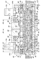
- the first formation cavity parts 64 are defined in a box 65 of the first die part 62 and are delimited, on the opposite side with respect to their mouth 64b, by a bottom 66.
- the bottom 66 of the first formation cavity parts 64 can be occupied at least partially by an extraction plug that can move on command along the axis 64a of the corresponding first formation cavity part 64 from an inactive position, in which it is spaced from the mouth 64b of the corresponding first formation cavity part 64, to an extraction position, in which it is moved toward the mouth 64b of the corresponding first formation cavity part 64 with respect to the inactive position.
- the extraction plug occupies completely the bottom 66 of the corresponding first formation cavity 64, constituting itself said bottom 66.
- the extraction plugs or the bottoms 66 of the various first formation cavity parts 64 are fixed to a single bottom supporting plate 67, which can move with respect to the box 65 of the first die part 62 parallel to the axes 64a of the first formation cavity parts 64, so as to actuate simultaneously the various extraction plugs or the various bottoms 66.
- the extraction plugs or the bottoms 66 of the various first formation cavity parts 64 are provided with corresponding cooling means constituted by ducts 68 that are extended inside the extraction plugs 66 and the bottom supporting plate 67 and can be connected to means for supplying a cooling fluid, which are of a known type and are not shown for the sake of simplicity.
- the second formation cavity parts 69 are defined in a box 70 of the second die part 63 and are delimited, on the opposite side with respect to their mouth 69b, by a corresponding bottom 71.
- the adjustment means 73 comprise means for varying the distance of the bottom 71 of each one of the second formation cavity parts 69 from the mouth 69b of the corresponding second formation cavity part 69.
- each bottom 71 of the second formation cavity parts 69 is occupied at least partially by an extraction plug 74 that is directed toward the mouth 69b of the second formation cavity part 69 and can move on command from an inactive position, in which it is spaced from the mouth 69b of the corresponding second formation cavity part 69, to an extraction position, in which it is moved toward the mouth 69b of the corresponding second formation cavity part 69 with respect to the inactive position.
- an extraction plug 74 that is directed toward the mouth 69b of the second formation cavity part 69 and can move on command from an inactive position, in which it is spaced from the mouth 69b of the corresponding second formation cavity part 69, to an extraction position, in which it is moved toward the mouth 69b of the corresponding second formation cavity part 69 with respect to the inactive position.
- the box 70 of the second die part 63 in which the second formation cavity parts 69 are defined, is fixed to a support 75, which in turn is fixed to a supporting beam 76.
- the supporting beam 76 is provided, in a per se known manner, with engagement means for the means for moving the second die part 63 with respect to the first die part 62.
- the engagement means for the movement means are constituted by brackets 77a, 77b that are fixed to the supporting beam 76 and are shown only in Figure 11 for the sake of simplicity.
- the movement means actuate the alternating movement of the second die part 63 toward or away from the first die part 62 so as to open and close the formation cavity parts 64, 69.
- the bottoms 71 of the second formation cavity parts 69 are fixed to a bottom supporting plate 78 that is accommodated, so that it can slide along a direction that is parallel to the axes 69a of the second formation cavity parts 69, within the support 75.
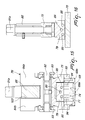
- the means for varying the distance of the bottoms 71 from the mouth 69b of the corresponding second formation cavity part 69 comprise at least one actuation shaft 79a, 79b, which is supported, so that it can rotate about its own axis, which is oriented at right angles to the central plane cited above, by the supporting beam 76.
- the actuation shaft 79a, 79b has an eccentric portion 80 that is connected to the bottom supporting plate 78.
- actuation shaft 79a, 79b there is a pair of actuation shafts 79a, 79b which have mutually parallel axes and are connected to corresponding actuation means 81 mounted on the supporting beam 76.
- the actuation means 81 can comprise a handwheel 82, which is connected, by means of a pair of reduction units 83a, 83b, to the pair of actuation shafts 79a, 79b.
- the actuation means 81 can comprise a servomotor that is connected to the pair of actuation shafts 79a, 79b and is connected functionally to an actuation and control element of the electronic type that supervises the operation of the entire apparatus and, in particular, is capable of performing the rotation, through angles of preset breadth, of the pair of actuation shafts 79a, 79b so as to perform the controlled movement of the bottoms 71 of the second formation cavity parts 69 parallel to the axis 69a of the corresponding second formation cavity part 69.
- the supporting beam 76 is provided with two shoulders 84a, 84b that define between them a seat 103 which accommodates an actuation beam 85 that connects the eccentric portions 80 of the actuation shafts 79a, 79b to the bottom supporting plate 78.
- the reduction units 83a, 83 be with the actuation handwheel 82 or, as an alternative, the servomotor, are mounted on the supporting beam 76 and the actuation shafts 79a, 79b are supported, so that they can rotate about their corresponding axes, by the supporting beam 76 by means of bearings 104.
- the eccentric portion 80 of each one of the actuation shafts 79a, 79b mates with a hole 86 that is defined in a bushing 87 that is accommodated in the actuation beam 85.
- Each extraction plug 74 is connected to the stem of the piston 88 of a pneumatic cylinder that is arranged in the bottom 71 of the corresponding second formation cavity part 69.
- each bottom 71 of the second formation cavity parts 69 constitutes the body of a pneumatic cylinder in which there is a cylindrical chamber that accommodates a piston 88, the stem of which is connected to a corresponding extraction plug 74.
- the various cylindrical chambers are connected to a duct 89 that is extended inside the bottom supporting plate 78 and the actuation beam 85 and can be connected to means for supplying a pressurized fluid in order to move the extraction plugs 74 in the direction of the mouth 69b of the corresponding second formation cavity part 69.
- the return motion of the extraction plugs 74 can be achieved in a per se known manner by means of springs.
- the actuation beam 85 is connected to the bottom supporting plates 78 by means of mutually spaced blocks 90.
- the two end blocks 90 are fixed to the actuation plate by means of screws 91 a, 91 b.
- the supporting beam 76 is fixed to the support 75 by means of pins 92 and engagement blocks 93, as shown in particular in Figure 15 .
- means for cooling the bottoms 71 of the second formation cavities 69 are provided.
- Such cooling means comprise a plurality of ducts 94 that are extended inside the various bottoms 71 and are connected to manifold ducts 95 that are defined inside the bottom supporting plate 78 and in turn are connected to an intake duct 96 and to a discharge duct 97, which are defined in the actuation beam 85 and can be connected to a circuit for supplying a cooling fluid, in a per se known manner.
- chutes 102 for removing the excess soap.
- the chutes 102 are fixed to the box 65 of the first die part 62, as shown in Figures 11 and 12 .
- the first die part 3, 62 can be provided with spacing pins 11a, 11b, 100a, 100b, which by mating with respective blocks 37a, 37b, 101a, 101b provided appropriately on the side of the second die part 4, 63 that faces the first die part 3, 62 ensure the placement of the bottom supporting plate 15, 67 during the step for forming the soap between the first formation cavity parts 2, 64 and the second formation cavity parts 8, 69.
- a bar of soap is arranged between the first die part 62 and the second die part 63.
- the second die part 63 is then moved toward the first die part 62 so as to produce the mating of the first formation cavity parts 64 with the second formation cavity parts 69, stamping the interposed bar of soap that is pushed so as to occupy the formation cavities, each of which is composed of a first formation cavity part 64 and a corresponding second formation cavity part 69 that are mutually coaxially coupled.
- the soap that is in excess with respect to what is needed to fill the formation cavities is moved away laterally through the chutes 102.
- the second die part 63 is then moved away from the first die part 62, thus opening the formation cavity parts 64, 69.
- the extraction plugs 74 placed in the second formation cavity parts 69 are actuated in order to perform their transition from the inactive position to the extraction position, so as to facilitate the separation of the stamped pieces of soap 72 from the second formation cavity parts 69. In this manner, the stamped pieces of soap 72 remain in the first formation cavity parts 64.
- the grip and removal means usually provided with suckers, intervene and engage the side of the pieces of soap 72 that protrudes from the mouth 64b of the first formation cavity parts 64.
- Such grip and removal means extract the pieces of stamped soap 72 from the first formation cavity parts 64 and move them away from the first die part 62.
- the extraction plugs or the bottom 66 of the first formation cavity parts 64 are actuated in order to perform their transition from the inactive position to the extraction position, i.e., moving them toward the mouth 64b of the first formation cavity parts 64 so as to assist the action of the grip and removal means.
- the pushing action of the extraction plugs or of the bottoms 66 of the first formation cavity parts 64 is particularly useful if the soap is sticky or if the pieces of soap 72 have a large surface in contact with the side walls of the first formation cavity parts 64, as occurs in the case of pieces of soap 72 that have a lateral surface that is cylindrical or has flat faces.
- a variation of the volume of the formation cavities is required, i.e., a variation of the volume of pieces of soap 72 to be stamped is required, it is sufficient to act on the handwheel 82 or actuate the servomotor, which by turning the actuation shafts 79a, 79b, by means of the coupling that exists between the eccentric portion 80 of the actuation shafts 79a, 79b and the actuation beam 85 that is connected to the bottom supporting plate 78 causes the simultaneous movement of the various bottoms 71 of the second formation cavity parts 69 parallel to the axis 69a of each second formation cavity part 69, varying the volume of the second formation cavity parts 69, as shown in particular in Figures 13 and 14 and consequently the total volume of the formation cavities, each constituted by the mating of a first formation cavity part 64 with a corresponding second formation cavity part 69.
- the apparatus according to the invention achieves fully the intended aim, since it allows to vary the volume of the formation cavities and consequently the volume of the stamped pieces of soap according to requirements.
- the materials used, as well as the dimensions, may be any according to requirements and to the state of the art.
Landscapes
- Engineering & Computer Science (AREA)
- Mechanical Engineering (AREA)
- Detergent Compositions (AREA)
Applications Claiming Priority (2)
| Application Number | Priority Date | Filing Date | Title |
|---|---|---|---|
| ITMI20140115 | 2014-01-29 | ||
| ITMI20141916 | 2014-11-07 |
Publications (1)
| Publication Number | Publication Date |
|---|---|
| EP2910367A1 true EP2910367A1 (fr) | 2015-08-26 |
Family
ID=52395005
Family Applications (1)
| Application Number | Title | Priority Date | Filing Date |
|---|---|---|---|
| EP15152895.7A Withdrawn EP2910367A1 (fr) | 2014-01-29 | 2015-01-28 | Appareil d'estampage de type estampage flash pour pains de savon, pour la production de savons de toilette, savons de blanchisserie ou similaires |
Country Status (1)
| Country | Link |
|---|---|
| EP (1) | EP2910367A1 (fr) |
Cited By (1)
| Publication number | Priority date | Publication date | Assignee | Title |
|---|---|---|---|---|
| IT201600108912A1 (it) * | 2016-10-27 | 2018-04-27 | Desmet Ballestra S P A In Breve Ballestra S P A | Stampo di una apparecchiatura di stampaggio per saponi e simili e relativa apparecchiatura di stampaggio |
Citations (8)
| Publication number | Priority date | Publication date | Assignee | Title |
|---|---|---|---|---|
| US1309986A (en) * | 1919-07-15 | Planograph co | ||
| US1391975A (en) * | 1920-06-05 | 1921-09-27 | American Cotton Oil Company | Method for molding and cooling soap |
| US1391972A (en) * | 1920-08-05 | 1921-09-27 | American Cotton Oil Company | Method and apparatus for molding soap |
| GB164341A (en) * | 1920-06-05 | 1922-10-06 | American Cotton Oil Company | Apparatus for molding soap |
| DE391694C (de) * | 1923-03-22 | 1924-03-11 | C E Rost & Co | Verfahren zum Vor- und Nachpressen von Seifenstuecken |
| DE482735C (de) * | 1928-02-21 | 1929-10-01 | Fritz Kilian | Vorrichtung zur Herstellung von Presslingen aus Weichpulver, insbesondere Seifenpulver, auf einer Matrizenpresse |
| FR920188A (fr) * | 1943-09-24 | 1947-03-31 | Perfectionnements aux machines pour former des tablettes ou d'autres objets à partir de matière pulvérisée, par compression | |
| WO1988005463A1 (fr) * | 1987-01-14 | 1988-07-28 | Costruzioni Meccaniche G. Mazzoni S.P.A. | Appareil de pressage servant a façonner des morceaux de materiaux a consistance pateuse, tels que du savon, et procede correspondant |
-
2015
- 2015-01-28 EP EP15152895.7A patent/EP2910367A1/fr not_active Withdrawn
Patent Citations (8)
| Publication number | Priority date | Publication date | Assignee | Title |
|---|---|---|---|---|
| US1309986A (en) * | 1919-07-15 | Planograph co | ||
| US1391975A (en) * | 1920-06-05 | 1921-09-27 | American Cotton Oil Company | Method for molding and cooling soap |
| GB164341A (en) * | 1920-06-05 | 1922-10-06 | American Cotton Oil Company | Apparatus for molding soap |
| US1391972A (en) * | 1920-08-05 | 1921-09-27 | American Cotton Oil Company | Method and apparatus for molding soap |
| DE391694C (de) * | 1923-03-22 | 1924-03-11 | C E Rost & Co | Verfahren zum Vor- und Nachpressen von Seifenstuecken |
| DE482735C (de) * | 1928-02-21 | 1929-10-01 | Fritz Kilian | Vorrichtung zur Herstellung von Presslingen aus Weichpulver, insbesondere Seifenpulver, auf einer Matrizenpresse |
| FR920188A (fr) * | 1943-09-24 | 1947-03-31 | Perfectionnements aux machines pour former des tablettes ou d'autres objets à partir de matière pulvérisée, par compression | |
| WO1988005463A1 (fr) * | 1987-01-14 | 1988-07-28 | Costruzioni Meccaniche G. Mazzoni S.P.A. | Appareil de pressage servant a façonner des morceaux de materiaux a consistance pateuse, tels que du savon, et procede correspondant |
Cited By (1)
| Publication number | Priority date | Publication date | Assignee | Title |
|---|---|---|---|---|
| IT201600108912A1 (it) * | 2016-10-27 | 2018-04-27 | Desmet Ballestra S P A In Breve Ballestra S P A | Stampo di una apparecchiatura di stampaggio per saponi e simili e relativa apparecchiatura di stampaggio |
Similar Documents
| Publication | Publication Date | Title |
|---|---|---|
| DE69416378T2 (de) | Verfahren und Vorrichtung zum Formpressen von Kunststoffgegenständen | |
| CN104174717B (zh) | 一种带宽度可调折弯模条结构的成型机 | |
| CN104757157A (zh) | 一种压制茶饼的装置及控制方法 | |
| CN201470857U (zh) | 全立式挤压铸造设备 | |
| CZ300898A3 (cs) | Způsob a zařízení pro lisování plastových výrobků | |
| EP2910367A1 (fr) | Appareil d'estampage de type estampage flash pour pains de savon, pour la production de savons de toilette, savons de blanchisserie ou similaires | |
| CN104190841A (zh) | 一种阀体毛坯锻造模具 | |
| JP2010207857A (ja) | 鍛造プレスにおけるノックアウト装置 | |
| EP2524743B1 (fr) | Outil de découpage avec dispositif pour remplacer au moins un poinçon | |
| EP2902180A1 (fr) | Appareil d'estampage de type estampage flash pour pains de savon, pour la production de savons de toilette, savons de blanchisserie ou autres | |
| JP6007833B2 (ja) | 回転式製造装置 | |
| US3547181A (en) | Casting apparatus | |
| US2867844A (en) | Press for molding powdered material | |
| US9421603B2 (en) | Forging press | |
| CN104368691A (zh) | 杠杆倒冲装置 | |
| US2220776A (en) | Pressure casting apparatus | |
| JP2012245562A (ja) | 粉末成形装置 | |
| EP3986695B1 (fr) | Outil de moulage et procede de moulage pour la fabrication de récipients avec contre-depouille | |
| KR101154256B1 (ko) | 프레스 금형용 밸런스 블록 높이 조절장치 | |
| US1904155A (en) | Ejecting mechanism | |
| CN208662278U (zh) | 金属接线盒加工装置中的冲孔加工机构 | |
| KR102010895B1 (ko) | 트랜스퍼성형장치 | |
| CN208230657U (zh) | 一种多用弯形模 | |
| KR200295047Y1 (ko) | 프레스의 열판 개폐장치 | |
| CN203327842U (zh) | 包子成型设备的面皮成型装置及相配套的给馅装置 |
Legal Events
| Date | Code | Title | Description |
|---|---|---|---|
| PUAI | Public reference made under article 153(3) epc to a published international application that has entered the european phase |
Free format text: ORIGINAL CODE: 0009012 |
|
| AK | Designated contracting states |
Kind code of ref document: A1 Designated state(s): AL AT BE BG CH CY CZ DE DK EE ES FI FR GB GR HR HU IE IS IT LI LT LU LV MC MK MT NL NO PL PT RO RS SE SI SK SM TR |
|
| AX | Request for extension of the european patent |
Extension state: BA ME |
|
| 17P | Request for examination filed |
Effective date: 20160226 |
|
| RBV | Designated contracting states (corrected) |
Designated state(s): AL AT BE BG CH CY CZ DE DK EE ES FI FR GB GR HR HU IE IS IT LI LT LU LV MC MK MT NL NO PL PT RO RS SE SI SK SM TR |
|
| 17Q | First examination report despatched |
Effective date: 20180703 |
|
| STAA | Information on the status of an ep patent application or granted ep patent |
Free format text: STATUS: THE APPLICATION IS DEEMED TO BE WITHDRAWN |
|
| 18D | Application deemed to be withdrawn |
Effective date: 20181114 |