EP2910390B1 - Pneu et procédé de production associé - Google Patents
Pneu et procédé de production associé Download PDFInfo
- Publication number
- EP2910390B1 EP2910390B1 EP13852743.7A EP13852743A EP2910390B1 EP 2910390 B1 EP2910390 B1 EP 2910390B1 EP 13852743 A EP13852743 A EP 13852743A EP 2910390 B1 EP2910390 B1 EP 2910390B1
- Authority
- EP
- European Patent Office
- Prior art keywords
- tire
- bead
- cord
- core piece
- core
- Prior art date
- Legal status (The legal status is an assumption and is not a legal conclusion. Google has not performed a legal analysis and makes no representation as to the accuracy of the status listed.)
- Active
Links
- 238000004519 manufacturing process Methods 0.000 title claims description 12
- 239000011324 bead Substances 0.000 claims description 116
- 238000004804 winding Methods 0.000 claims description 46
- 238000000034 method Methods 0.000 description 9
- 229920001971 elastomer Polymers 0.000 description 6
- 239000005060 rubber Substances 0.000 description 6
- 238000012360 testing method Methods 0.000 description 6
- 238000004073 vulcanization Methods 0.000 description 5
- 229920000297 Rayon Polymers 0.000 description 4
- 239000004760 aramid Substances 0.000 description 4
- 229920003235 aromatic polyamide Polymers 0.000 description 4
- 230000000694 effects Effects 0.000 description 4
- 239000002964 rayon Substances 0.000 description 4
- 238000010586 diagram Methods 0.000 description 3
- 238000010438 heat treatment Methods 0.000 description 2
- 241000254043 Melolonthinae Species 0.000 description 1
- 230000001133 acceleration Effects 0.000 description 1
- 230000015572 biosynthetic process Effects 0.000 description 1
- 238000012790 confirmation Methods 0.000 description 1
- 238000005516 engineering process Methods 0.000 description 1
- 238000011156 evaluation Methods 0.000 description 1
- 230000002349 favourable effect Effects 0.000 description 1
- 239000000835 fiber Substances 0.000 description 1
- 239000000463 material Substances 0.000 description 1
- 238000003825 pressing Methods 0.000 description 1
- 230000003014 reinforcing effect Effects 0.000 description 1
- 238000011160 research Methods 0.000 description 1
Images





Classifications
-
- B—PERFORMING OPERATIONS; TRANSPORTING
- B60—VEHICLES IN GENERAL
- B60C—VEHICLE TYRES; TYRE INFLATION; TYRE CHANGING; CONNECTING VALVES TO INFLATABLE ELASTIC BODIES IN GENERAL; DEVICES OR ARRANGEMENTS RELATED TO TYRES
- B60C15/00—Tyre beads, e.g. ply turn-up or overlap
- B60C15/04—Bead cores
- B60C15/05—Bead cores multiple, i.e. with two or more cores in each bead
-
- B—PERFORMING OPERATIONS; TRANSPORTING
- B29—WORKING OF PLASTICS; WORKING OF SUBSTANCES IN A PLASTIC STATE IN GENERAL
- B29D—PRODUCING PARTICULAR ARTICLES FROM PLASTICS OR FROM SUBSTANCES IN A PLASTIC STATE
- B29D30/00—Producing pneumatic or solid tyres or parts thereof
- B29D30/06—Pneumatic tyres or parts thereof (e.g. produced by casting, moulding, compression moulding, injection moulding, centrifugal casting)
- B29D30/08—Building tyres
- B29D30/10—Building tyres on round cores, i.e. the shape of the core is approximately identical with the shape of the completed tyre
-
- B—PERFORMING OPERATIONS; TRANSPORTING
- B29—WORKING OF PLASTICS; WORKING OF SUBSTANCES IN A PLASTIC STATE IN GENERAL
- B29D—PRODUCING PARTICULAR ARTICLES FROM PLASTICS OR FROM SUBSTANCES IN A PLASTIC STATE
- B29D30/00—Producing pneumatic or solid tyres or parts thereof
- B29D30/06—Pneumatic tyres or parts thereof (e.g. produced by casting, moulding, compression moulding, injection moulding, centrifugal casting)
- B29D30/08—Building tyres
- B29D30/10—Building tyres on round cores, i.e. the shape of the core is approximately identical with the shape of the completed tyre
- B29D30/18—Fitting the bead-rings or bead-cores; Folding the textile layers around the rings or cores
-
- B—PERFORMING OPERATIONS; TRANSPORTING
- B29—WORKING OF PLASTICS; WORKING OF SUBSTANCES IN A PLASTIC STATE IN GENERAL
- B29D—PRODUCING PARTICULAR ARTICLES FROM PLASTICS OR FROM SUBSTANCES IN A PLASTIC STATE
- B29D30/00—Producing pneumatic or solid tyres or parts thereof
- B29D30/06—Pneumatic tyres or parts thereof (e.g. produced by casting, moulding, compression moulding, injection moulding, centrifugal casting)
- B29D30/48—Bead-rings or bead-cores; Treatment thereof prior to building the tyre
-
- B—PERFORMING OPERATIONS; TRANSPORTING
- B60—VEHICLES IN GENERAL
- B60C—VEHICLE TYRES; TYRE INFLATION; TYRE CHANGING; CONNECTING VALVES TO INFLATABLE ELASTIC BODIES IN GENERAL; DEVICES OR ARRANGEMENTS RELATED TO TYRES
- B60C15/00—Tyre beads, e.g. ply turn-up or overlap
- B60C15/0009—Tyre beads, e.g. ply turn-up or overlap features of the carcass terminal portion
- B60C15/0018—Tyre beads, e.g. ply turn-up or overlap features of the carcass terminal portion not folded around the bead core, e.g. floating or down ply
-
- B—PERFORMING OPERATIONS; TRANSPORTING
- B60—VEHICLES IN GENERAL
- B60C—VEHICLE TYRES; TYRE INFLATION; TYRE CHANGING; CONNECTING VALVES TO INFLATABLE ELASTIC BODIES IN GENERAL; DEVICES OR ARRANGEMENTS RELATED TO TYRES
- B60C15/00—Tyre beads, e.g. ply turn-up or overlap
- B60C15/04—Bead cores
-
- B—PERFORMING OPERATIONS; TRANSPORTING
- B60—VEHICLES IN GENERAL
- B60C—VEHICLE TYRES; TYRE INFLATION; TYRE CHANGING; CONNECTING VALVES TO INFLATABLE ELASTIC BODIES IN GENERAL; DEVICES OR ARRANGEMENTS RELATED TO TYRES
- B60C5/00—Inflatable pneumatic tyres or inner tubes
- B60C5/12—Inflatable pneumatic tyres or inner tubes without separate inflatable inserts, e.g. tubeless tyres with transverse section open to the rim
-
- B—PERFORMING OPERATIONS; TRANSPORTING
- B60—VEHICLES IN GENERAL
- B60C—VEHICLE TYRES; TYRE INFLATION; TYRE CHANGING; CONNECTING VALVES TO INFLATABLE ELASTIC BODIES IN GENERAL; DEVICES OR ARRANGEMENTS RELATED TO TYRES
- B60C9/00—Reinforcements or ply arrangement of pneumatic tyres
- B60C9/02—Carcasses
-
- B—PERFORMING OPERATIONS; TRANSPORTING
- B29—WORKING OF PLASTICS; WORKING OF SUBSTANCES IN A PLASTIC STATE IN GENERAL
- B29D—PRODUCING PARTICULAR ARTICLES FROM PLASTICS OR FROM SUBSTANCES IN A PLASTIC STATE
- B29D30/00—Producing pneumatic or solid tyres or parts thereof
- B29D30/06—Pneumatic tyres or parts thereof (e.g. produced by casting, moulding, compression moulding, injection moulding, centrifugal casting)
- B29D30/48—Bead-rings or bead-cores; Treatment thereof prior to building the tyre
- B29D2030/487—Forming devices for manufacturing the beads
-
- B—PERFORMING OPERATIONS; TRANSPORTING
- B60—VEHICLES IN GENERAL
- B60C—VEHICLE TYRES; TYRE INFLATION; TYRE CHANGING; CONNECTING VALVES TO INFLATABLE ELASTIC BODIES IN GENERAL; DEVICES OR ARRANGEMENTS RELATED TO TYRES
- B60C9/00—Reinforcements or ply arrangement of pneumatic tyres
- B60C9/02—Carcasses
- B60C9/04—Carcasses the reinforcing cords of each carcass ply arranged in a substantially parallel relationship
- B60C2009/0416—Physical properties or dimensions of the carcass cords
-
- B—PERFORMING OPERATIONS; TRANSPORTING
- B60—VEHICLES IN GENERAL
- B60C—VEHICLE TYRES; TYRE INFLATION; TYRE CHANGING; CONNECTING VALVES TO INFLATABLE ELASTIC BODIES IN GENERAL; DEVICES OR ARRANGEMENTS RELATED TO TYRES
- B60C15/00—Tyre beads, e.g. ply turn-up or overlap
- B60C15/04—Bead cores
- B60C2015/044—Bead cores characterised by a wrapping layer
Definitions
- the present invention relates to a pneumatic tire and a production method thereof having a bead structure where a radially inner end portion of a carcass ply is held between axially inner and outer core pieces.
- the features of the preamble of the independent claims are known from JP 10-305710 A and US 2006/0096690 A1 .
- Related technologies are known from us 2006/0266458 A1 , JP 2006-044339 A , EP 2 684 712 A1 .
- a production method by use of a rigid core (a) having an outer surface configuration being nearly identical to a tire inner surface configuration of a vulcanized tire (hereinafter called "core method") has been proposed.
- tire components such as an inner liner rubber, a carcass ply, a bead core, a belt ply, a sidewall rubber and a tread rubber are sequentially applied on the rigid core (a).
- the unvulcanized tire (t) is set in a vulcanization mold (b) with the rigid core (a) and vulcanized between the rigid core (a) as an inner mold and the vulcanization mold (b) as an outer mold.
- Patent Document 1 discloses a structure shown in Fig. 11 (B) . That is to say, the bead core (d) is divided into axially inner and outer core pieces (d1, d2). And, the both end portions of the carcass ply (c) are held between the inner and outer core pieces (d1, d2).
- the inner and outer core pieces (d1, d2) are formed as a helical body formed by helically winding a bead cord (steal cord) (e) around the tire axis.
- Patent Document 1 Japanese published unexamined application No. 2006-160236
- the present invention is grounded in limiting a final twisting direction and a winding direction of the bead cord in inner and outer core pieces and being capable of applying the tension to a carcass cord while suppressing the loosing of the carcass cord from the inner and outer core pieces so as to intend to provide a pneumatic tire which can improve steering stability, and a manufacturing method thereof.
- a pneumatic tire comprises a carcass comprising a carcass ply extending from a tread portion through a sidewall portion to a bead core of a bead portion.
- the bead core is made of an axially inner and outer core pieces, and radially inner end portion of the carcass ply is held between the inner and outer core pieces without turning-up around the bead core.
- the inner and outer core pieces are formed of a helical body by helically winding a bead cord made of a plurality of twisted steal wires around a tire axis from radially inward to outward.
- the final twisting direction of the bead cord is the same as the winding direction of the bead cord around the tire axis in a side view from an axial outward of the tire.
- the final twisting direction of the bead cord is opposite to the winding direction of the bead cord around the tire axis in the side view from the axial outward of the tire.
- a production method for a pneumatic tire comprises a carcass comprising a carcass ply extending from a tread portion through a sidewall portion to a bead core of a bead portion.
- the production method comprises a green tire forming step of forming a green tire by use of a rigid core having a tire forming surface on the outer surface by sequentially applying unvulcanized tire components including the bead core and the carcass ply on the tire forming surface.
- the green tire forming step comprises a first core piece step of forming an inner core piece on the tire forming surface by helically winding a bead cord made of a plurality of twisted steal wires around the tire axis from radially inward to outward, a carcass forming step comprising a step of applying a radially inner end portion of the carcass ply to the axially outsi de surface of the inner core piece, and a second core piece step of forming the outer core piece on the axial outward of the tire of the radially inner end portion of the carcass ply by helically winding the bead cord around the tire axis from radially inward to outward.
- the final twisting di recti on of the bead cord is the same di recti on as the winding di recti on of the bead cord around the tire axis in the side view from the axial outward of the tire.
- the final twisting direction of the bead cord is opposite to the winding direction of the bead cord around the tire axis in the side view from the axial outward of the tire.
- the final twisting direction of the bead cord is the same as the winding direction of the bead cord around the tire axis in the side view from the axial outward of the tire.
- the final twisting direction of the bead cord is opposite to the winding direction of the bead cord around the tire axis in the side view from the axial outward of the tire.
- a pneumatic tire 1 according to the present embodiment comprises a carcass 6 extending from a tread portion 2 through a sidewall portion 3 to a bead core 5 of a bead portion 4.
- a belt layer 7 is disposed radially outward of the carcass 6 and inside the tread portion 2.
- the belt layer 7 is formed of at least one belt ply, two belt plies 7A, 7B in the present embodiment, where belt cords are arranged at an angle of 10 to 35 degrees with respect to the tire circumferential direction, for example.
- the belt cords of the belt layer 7 intersect one another between plies. This increases belt rigidity and strongly reinforces the tread portion 2.
- a band layer 9 made of a band cord spirally wound with respect to the circumferential direction for improving high-speed durability and the like.
- a pair of edge band plies to cover only the axially outer end portion of the belt layer 7 and a full band ply to cover substantially overall width of the belt layer 7 can be employed.
- the present embodiment shows a case that the band layer 9 is formed of a single full band ply.
- the carcass 6 is formed of at least one carcass ply, one carcass ply 6A in the present embodiment, where an organic fiber carcass cord is arranged at an angle of 70 to 90 degrees with respect to the tire circumferential direction, for example.
- the carcass ply 6A has a toroidal form extending between the bead portions 4, 4. And the radially inner end portion 6AE of the carcass ply 6A is not turned up around the bead core 5 but is held in the bead cores 5.
- the bead core 5 is made of axially inner and outer core pieces 5i, 5o. And the radially inner end portion 6AE of the carcass ply 6A is held between the inner and outer core pieces 5i, 5o.
- the bead portion 4 is provided with inner and outer bead apex rubbers 8i, 8o extending from the inner and outer core pieces 5i, 5o toward the radially outward respectively in a tapered manner, thereby reinforcing between the bead portion 4 and the sidewall portion 3.
- the sign 15 in drawings means a chafer rubber for preventing rim shifting.
- the inner and outer core pieces 5i, 5o are formed of a helical body made by helically winding a bead cord 10 from the radially inward to the radially outward around the tire axis J.
- the present embodiment shows a case that, as shown in Fig. 1 , each of the core pieces 5i, 5o forms a line in the tire axial direction. Therefore, within a limited winding number of the bead cord 10, the radial height of the core piece 5i, 5o can be set at a maximum, the area of contact with the carcass ply 6A can be increased, and the locking force to the both end portions 6AE of the carcass ply 6A can be improved. Moreover, upon request, one or both of the core pieces 5i, 5o can be also formed in two lines to improve bead rigidity.
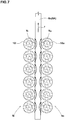
- each of the respective core pieces 5i, 5o is formed as a helical form by pressing the bead cord 10 against a rotating rigid core (a).
- a rotating rigid core
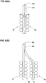
- Fi gs. 2 and 3 show a case that each of the wi ndi ng di recti ons Ri and Ro is "counterclockwise rotation".
- a Z-twist cord of which final twi sti ng di recti on Ti is "counterclockwise rotation" is employed as the bead cord 10i.
- This final twisting direction Ti is the same di recti on as the winding di recti on Ri.
- a S-twist cord of which final twisting direction To is "clockwise rotation” is employed as the bead cord 100.
- This final twi sti ng di recti on To is the opposite direction to the winding direction Ro.
- the bead cord 10i is, as shown in Fig. 5 , made of a plurality of steal wires F by twisting together.
- the bead cord 10i has a layer twisting structure comprising a core 11 made by twisting three steal wires F together, and a sheath 12 made by twisting eight steal wires F together disposed outside thereof.
- the twisting direction of the sheath 12 (equivalent to the final twisting direction Ti) is defined as the "counterclockwise rotation" (Z-twist).
- the bead cord 10o has, as shown in Fig. 6 , the same structure as the bead cord 10i except the twisting direction.
- the twisting direction of the sheath 12 (equivalent to the final twisting direction To) is defined as the "clockwise rotation" (S-twist).
- twisting structures can be employed such as a bundle-twisting structure (1 ⁇ n) made by twisting n number of steal wires F, a slash-twisting structure (m/n) made by twisting to have the same twisting direction and the same twisting pitch, and a multi-twisting structure (m ⁇ n) made by twisting m number of strands (each strand obtained by first twisting n number of steal wires F), for example.
- the steering stability is more effectively improved when the heat shrinkage of the carcass cord 6c at 180 degrees is preferably not less than 1.5%, more preferably not less than 2.0%.
- the above-mentioned "heat shrinkage” means a dry-heat shrinkage after heating of the cord for five minutes at 180 degrees C under no-load.
- the number of the carcass ply 6A is plural, two carcass plies 6A for example, as shown in Fig. 9 (A) , the plurality of carcass plies 6A can be held between the inner and outer core pieces 5i, 5o.
- Fig. 9 (B) it is preferable to provide a plurality of the pairs of inner and outer core pieces 5i, 5o and to hold each of the carcass plies 6A between the respective inner and outer core pieces 5i, 5o so as to improve the binding force.
- This production method comprises a green tire forming step and a vulcanizing step (shown in Fig. 11 (A) ).
- a green tire forming step by use of a rigid core (a) provided with a tire forming surface (as) on an outer surface (shown in Fig. 4 ), unvulcanized tire components are serially applied on the tire forming surface (as). Thus a green tire (t) is formed.
- the green tire (t) is set in a vulcanization mold (b) with the rigid core (a) and vulcanized and formed.
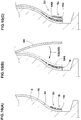
- the green tire forming step as shown in Figs. 10 (A) - (C) , comprises a first core piece step S1, a carcass forming step S2, and a second core piece step s3.
- the bead cord 10i rubberized with an unvulcanized tire is helically winding from radially inward to outward around the tire axis on the tire forming surface (as) so as to form the inner core piece 5i.
- the sign 16 means an inner liner rubber.
- the carcass forming step S2 comprises a step S2a of applying the radially inner end portion 6AE of the carcass ply 6A to the axially outside surface of the inner core piece 5i.
- the rubberized bead cord 10o is helically wound around the ti re axis from radially inward to outward so as to form the outer core piece 5o.
- the final twisting direction Ti of the bead cord 10i has the same direction as the winding direction Ri of the bead cord 10i around the tire axis J in the side view from the axial outward of the tire.
- the final twisting direction To of the bead cord 10o has an opposite direction to the winding direction Ro of the bead cord 10o around the ti re axis J in the side view from the axial outward of the tire.
- a pneumatic tire (225/40R18) having an inner structure shown in Fig. 1 was made in the core method.
- the bead structure of each test tire was based on the specifications shown in Table 1.
- Each test tire was tested in steering stability, and the test results were compared.
- the bead cores on one side and the other side of the tire equator have same structures as shown in Table 1.
- the bead cord shown in Table 1 has the same specifications such as a twisting structure (2/7 ⁇ 0.37), diameter of cord of 1.41 mm, and twisting pitch of 50 mm, except the twisting direction.
- cords are PET of 1670/2 dtex, rayon of 1840/2 dtex, aramid of 1100/2 dtex.
Landscapes
- Engineering & Computer Science (AREA)
- Mechanical Engineering (AREA)
- Tires In General (AREA)
- Tyre Moulding (AREA)
Claims (6)
- Bandage pneumatique (1) comprenant une carcasse (6) comprenant une nappe de carcasse (6A) qui s'étend depuis une portion formant bande de roulement (2) en traversant une portion formant paroi latérale (3) jusqu'à une âme de talon (5) d'une portion formant talon (4) ; dans lequel
l'âme de talon (5) est constituée d'une pièce d'âme intérieure et d'une pièce d'âme extérieure en sens axial (5i, 5o), et une portion d'extrémité radialement intérieure (6AE) de la nappe de carcasse (6A) est maintenue entre la pièce d'âme intérieure et la pièce d'âme extérieure (5i, 5o) sans être retroussée autour de l'âme de talon (5) ; et
la pièce d'âme intérieure et la pièce d'âme extérieure (5i, 5o) sont formées d'un corps hélicoïdal en enroulant de manière hélicoïdale un câblé de talon (10i, 10o) fait d'une pluralité de fils d'acier torsadés (F) autour d'un axe (J) du pneumatique radialement depuis l'intérieur vers l'extérieur ;
caractérisé en ce que
dans la pièce d'âme intérieure (5i), la direction de torsade finale (Ti) du câblé de talon (10i) est la même que la direction d'enroulement (Ri) du câblé de talon (10i) autour de l'axe (J) du pneumatique dans une vue latérale depuis l'extérieur du pneumatique en sens axial, et dans la pièce d'âme extérieure (5o), la direction de torsade finale (To) du câblé de talon (10o) est opposée à la direction de roulement (Ro) du câblé de talon (10o) autour de l'axe (J) du pneumatique dans la vue latérale depuis l'extérieur du pneumatique en sens axial. - Bandage pneumatique selon la revendication 1, dans lequel la direction d'enroulement (Ri) du câblé de talon (10i) autour de l'axe (J) du pneumatique dans la pièce d'âme intérieure (5i) est la même que la direction d'enroulement (Ro) du câblé de talon (10o) autour de l'axe (J) du pneumatique dans la pièce d'âme extérieure (5o).
- Bandage pneumatique selon la revendication 1 ou 2, dans lequel la nappe de carcasse (6A) a un câblé de carcasse (6C) dont la rétraction à chaud (f) à 180° C n'est pas inférieure à 1,5 %.
- Procédé de production pour un bandage pneumatique (1) comprenant une carcasse (6) comprenant une nappe de carcasse (6A) s'étendant depuis une portion formant bande de roulement (2) en traversant une portion formant paroi latérale (3) jusqu'à une âme de talon (5) d'une portion formant talon (4), dans lequel
le procédé de production comprend une étape de formation d'un pneumatique cru consistant à former un pneumatique cru en utilisant un noyau rigide ayant une surface de formation de pneumatique sur la surface extérieure en appliquant séquentiellement des composants de pneumatique non vulcanisés incluant l'âme de talon et la nappe de carcasse sur la surface de formation de pneumatique ;
caractérisé en ce que l'étape de formation d'un pneumatique cru comprend une étape de formation d'une première pièce d'âme consistant à former une pièce d'âme intérieure (5i) sur la surface de formation de pneumatique en enroulant en hélice un câblé de talon (10ai) fait d'une pluralité de fils d'acier torsadés (F) autour de l'axe (J) du pneumatique depuis l'intérieur vers l'extérieur en sens radial,
une étape de formation de carcasse comprenant une étape consistant à appliquer une portion d'extrémité radialement intérieure (6AE) de la nappe de carcasse (6A) sur la surface axialement extérieure de la pièce d'âme intérieure (5i), et
une étape de formation d'une seconde pièce d'âme consistant à former une pièce d'âme extérieure (5o) sur l'extérieur du pneumatique en sens axial de la portion d'extrémité radialement intérieure (6AE) de la nappe de carcasse (6A) en enroulant en hélice le câblé de talon (10o) autour de l'axe (J) du pneumatique depuis l'intérieur vers l'extérieur en sens radial ; et
dans l'étape de formation d'une première pièce d'âme, la direction de torsade finale (Ti) du câblé de talon (10i) est la même direction que la direction d'enroulement (Ri) du câblé de talon (10i) autour de l'axe (J) du pneumatique dans une vue latérale depuis l'extérieur du pneumatique en sens axial, et
dans l'étape de formation de la seconde pièce d'âme, la direction de torsade finale (To) du câblé de talon (10o) est opposée à la direction d'enroulement (Ro) du câblé de talon (10o) autour de l'axe (J) du pneumatique dans la vue latérale depuis l'extérieur du pneumatique en sens axial. - Procédé de production pour un bandage pneumatique selon la revendication 4, dans lequel la direction d'enroulement (Ri) du câblé de talon (10i) dans l'étape de formation de la première pièce d'âme est la même que la direction d'enroulement (Ro) du câblé de talon (10o) dans l'étape de formation de la seconde pièce d'âme.
- Procédé de production pour un bandage pneumatique selon la revendication 4 ou 5, dans lequel la nappe de carcasse (6A) a un câblé de carcasse (6C) dont la rétraction à chaud (f) à 180 °C n'est pas inférieure à 1,5%.
Applications Claiming Priority (2)
| Application Number | Priority Date | Filing Date | Title |
|---|---|---|---|
| JP2012247715A JP6074230B2 (ja) | 2012-11-09 | 2012-11-09 | 空気入りタイヤ、及びその製造方法 |
| PCT/JP2013/077132 WO2014073303A1 (fr) | 2012-11-09 | 2013-10-04 | Pneu et procédé de production associé |
Publications (3)
| Publication Number | Publication Date |
|---|---|
| EP2910390A1 EP2910390A1 (fr) | 2015-08-26 |
| EP2910390A4 EP2910390A4 (fr) | 2016-05-25 |
| EP2910390B1 true EP2910390B1 (fr) | 2019-01-16 |
Family
ID=50684420
Family Applications (1)
| Application Number | Title | Priority Date | Filing Date |
|---|---|---|---|
| EP13852743.7A Active EP2910390B1 (fr) | 2012-11-09 | 2013-10-04 | Pneu et procédé de production associé |
Country Status (5)
| Country | Link |
|---|---|
| US (1) | US10189317B2 (fr) |
| EP (1) | EP2910390B1 (fr) |
| JP (1) | JP6074230B2 (fr) |
| CN (2) | CN108274959B (fr) |
| WO (1) | WO2014073303A1 (fr) |
Families Citing this family (3)
| Publication number | Priority date | Publication date | Assignee | Title |
|---|---|---|---|---|
| JP5973955B2 (ja) * | 2013-05-07 | 2016-08-23 | 住友ゴム工業株式会社 | 空気入りタイヤ |
| JP6848262B2 (ja) * | 2016-08-22 | 2021-03-24 | 住友ゴム工業株式会社 | 空気入りタイヤ |
| CN116171229A (zh) * | 2020-10-09 | 2023-05-26 | 米其林集团总公司 | 包括单个胎体层的轮胎 |
Family Cites Families (23)
| Publication number | Priority date | Publication date | Assignee | Title |
|---|---|---|---|---|
| FR2299168A2 (fr) * | 1975-01-29 | 1976-08-27 | Michelin & Cie | Perfectionnements aux enveloppes de pneumatiques |
| FR2694521A1 (fr) * | 1992-08-05 | 1994-02-11 | Sedepro | Ancrage de la carcasse d'un pneumatique. |
| FR2736006A1 (fr) * | 1995-06-29 | 1997-01-03 | Sedepro | Pneumatique comportant des cables circonferentiels pour ancrer la carcasse, procede de preparation de tels cables |
| JP3777241B2 (ja) * | 1997-05-06 | 2006-05-24 | 横浜ゴム株式会社 | 空気入りラジアルタイヤ |
| JP3735447B2 (ja) * | 1997-06-09 | 2006-01-18 | 横浜ゴム株式会社 | 空気入りタイヤ |
| JP2001097010A (ja) * | 1999-09-30 | 2001-04-10 | Bridgestone Corp | 空気入りタイヤ |
| ATE298674T1 (de) * | 1999-12-03 | 2005-07-15 | Michelin Soc Tech | Wulst für notlaufreifen |
| KR20020060246A (ko) * | 1999-12-03 | 2002-07-16 | 미첼 롤리에르 | 확장된 이동성을 가진 타이어 비드 |
| JP2002012011A (ja) * | 2000-06-29 | 2002-01-15 | Bridgestone Corp | 空気入りタイヤ |
| CN100391753C (zh) * | 2002-07-23 | 2008-06-04 | 米其林技术公司 | 具有非直线固定加强件的轮胎 |
| JP4235032B2 (ja) * | 2003-05-23 | 2009-03-04 | 不二精工株式会社 | ビードコア及びそれを用いた空気入りラジアルタイヤ |
| FR2870164B1 (fr) * | 2004-05-12 | 2006-07-14 | Michelin Soc Tech | Pneumatique et composite metal/caoutchouc pour pneumatique |
| JP2006044339A (ja) * | 2004-08-02 | 2006-02-16 | Yokohama Rubber Co Ltd:The | 空気入りラジアルタイヤ |
| JP4695429B2 (ja) * | 2004-11-11 | 2011-06-08 | 住友ゴム工業株式会社 | 空気入りタイヤ及びその製造方法 |
| DE102005000755A1 (de) * | 2005-01-04 | 2006-07-20 | Continental Aktiengesellschaft | Fahrzeugluftreifen |
| JP4312173B2 (ja) * | 2005-05-24 | 2009-08-12 | 住友ゴム工業株式会社 | 自動二輪車用空気入りタイヤ |
| AR060523A1 (es) | 2006-04-19 | 2008-06-25 | Pioneer Hi Bred Int | Moleculas de polinucleotidos aislados que corresponden a alelos mutantes y tipo salvaje del gen de maiz d9 y metodos para usarlas |
| JP2010115957A (ja) * | 2008-11-11 | 2010-05-27 | Bridgestone Corp | 空気入りタイヤのビード部構造 |
| JP5227392B2 (ja) * | 2010-12-16 | 2013-07-03 | 住友ゴム工業株式会社 | 空気入りタイヤ及び空気入りタイヤの製造方法 |
| JP5302987B2 (ja) * | 2011-01-31 | 2013-10-02 | 住友ゴム工業株式会社 | 空気入りタイヤの製造方法 |
| JP5144783B2 (ja) | 2011-04-08 | 2013-02-13 | 住友ゴム工業株式会社 | 空気入りタイヤ、及びその製造方法 |
| JP6034803B2 (ja) * | 2011-12-15 | 2016-11-30 | 住友ゴム工業株式会社 | タイヤの製造方法 |
| JP6043553B2 (ja) * | 2012-09-10 | 2016-12-14 | 住友ゴム工業株式会社 | 空気入りタイヤ |
-
2012
- 2012-11-09 JP JP2012247715A patent/JP6074230B2/ja not_active Expired - Fee Related
-
2013
- 2013-10-04 WO PCT/JP2013/077132 patent/WO2014073303A1/fr not_active Ceased
- 2013-10-04 US US14/436,758 patent/US10189317B2/en active Active
- 2013-10-04 CN CN201810182710.9A patent/CN108274959B/zh active Active
- 2013-10-04 CN CN201380055847.3A patent/CN104768778B/zh active Active
- 2013-10-04 EP EP13852743.7A patent/EP2910390B1/fr active Active
Also Published As
| Publication number | Publication date |
|---|---|
| CN104768778B (zh) | 2018-09-21 |
| CN108274959A (zh) | 2018-07-13 |
| JP6074230B2 (ja) | 2017-02-01 |
| WO2014073303A1 (fr) | 2014-05-15 |
| CN104768778A (zh) | 2015-07-08 |
| JP2014094684A (ja) | 2014-05-22 |
| CN108274959B (zh) | 2020-06-09 |
| EP2910390A1 (fr) | 2015-08-26 |
| EP2910390A4 (fr) | 2016-05-25 |
| US10189317B2 (en) | 2019-01-29 |
| US20150258862A1 (en) | 2015-09-17 |
Similar Documents
| Publication | Publication Date | Title |
|---|---|---|
| EP2308694B1 (fr) | Pneu | |
| EP2098385B1 (fr) | Pneu | |
| EP2783842B1 (fr) | Procédé de fabrication de pneumatique | |
| EP2684712B1 (fr) | Pneumatique et procédé de fabrication de ce pneumatique | |
| EP3459763B1 (fr) | Pneumatique | |
| EP3135465B1 (fr) | Pneumatique et procédé de production de pneumatique | |
| EP2987657B1 (fr) | Pneumatique | |
| EP2910390B1 (fr) | Pneu et procédé de production associé | |
| EP2810792B1 (fr) | Pneumatique | |
| EP3061630B1 (fr) | Pneumatique | |
| JPH0396402A (ja) | 空気入りラジアルタイヤ | |
| EP2808178B1 (fr) | Élément de renforcement de pneumatique et pneumatique utilisant cet élément | |
| JP2018020607A (ja) | コード・ゴム複合体及び空気入りタイヤ | |
| EP3792079B1 (fr) | Pneu pour fonctionnement intensif | |
| US12539717B2 (en) | Pneumatic tire | |
| JP2011042339A (ja) | 空気入りタイヤ | |
| EP3956157B1 (fr) | Câble hybride et pneu avec câble hybride | |
| JP6247730B2 (ja) | 空気入りタイヤ、及びその製造方法 | |
| EP3335906B1 (fr) | Pneumatique | |
| WO2024134977A1 (fr) | Pneu de motocyclette | |
| JP2015077884A (ja) | 空気入りタイヤ |
Legal Events
| Date | Code | Title | Description |
|---|---|---|---|
| PUAI | Public reference made under article 153(3) epc to a published international application that has entered the european phase |
Free format text: ORIGINAL CODE: 0009012 |
|
| 17P | Request for examination filed |
Effective date: 20150519 |
|
| AK | Designated contracting states |
Kind code of ref document: A1 Designated state(s): AL AT BE BG CH CY CZ DE DK EE ES FI FR GB GR HR HU IE IS IT LI LT LU LV MC MK MT NL NO PL PT RO RS SE SI SK SM TR |
|
| AX | Request for extension of the european patent |
Extension state: BA ME |
|
| DAX | Request for extension of the european patent (deleted) | ||
| RA4 | Supplementary search report drawn up and despatched (corrected) |
Effective date: 20160428 |
|
| RIC1 | Information provided on ipc code assigned before grant |
Ipc: B60C 9/00 20060101ALI20160421BHEP Ipc: B29D 30/10 20060101ALI20160421BHEP Ipc: B60C 15/04 20060101ALI20160421BHEP Ipc: B60C 15/00 20060101AFI20160421BHEP |
|
| GRAP | Despatch of communication of intention to grant a patent |
Free format text: ORIGINAL CODE: EPIDOSNIGR1 |
|
| STAA | Information on the status of an ep patent application or granted ep patent |
Free format text: STATUS: GRANT OF PATENT IS INTENDED |
|
| INTG | Intention to grant announced |
Effective date: 20180802 |
|
| GRAS | Grant fee paid |
Free format text: ORIGINAL CODE: EPIDOSNIGR3 |
|
| GRAA | (expected) grant |
Free format text: ORIGINAL CODE: 0009210 |
|
| STAA | Information on the status of an ep patent application or granted ep patent |
Free format text: STATUS: THE PATENT HAS BEEN GRANTED |
|
| AK | Designated contracting states |
Kind code of ref document: B1 Designated state(s): AL AT BE BG CH CY CZ DE DK EE ES FI FR GB GR HR HU IE IS IT LI LT LU LV MC MK MT NL NO PL PT RO RS SE SI SK SM TR |
|
| REG | Reference to a national code |
Ref country code: GB Ref legal event code: FG4D |
|
| REG | Reference to a national code |
Ref country code: CH Ref legal event code: EP |
|
| REG | Reference to a national code |
Ref country code: IE Ref legal event code: FG4D |
|
| REG | Reference to a national code |
Ref country code: DE Ref legal event code: R096 Ref document number: 602013050043 Country of ref document: DE |
|
| REG | Reference to a national code |
Ref country code: AT Ref legal event code: REF Ref document number: 1089444 Country of ref document: AT Kind code of ref document: T Effective date: 20190215 |
|
| REG | Reference to a national code |
Ref country code: NL Ref legal event code: MP Effective date: 20190116 |
|
| REG | Reference to a national code |
Ref country code: LT Ref legal event code: MG4D |
|
| PG25 | Lapsed in a contracting state [announced via postgrant information from national office to epo] |
Ref country code: NL Free format text: LAPSE BECAUSE OF FAILURE TO SUBMIT A TRANSLATION OF THE DESCRIPTION OR TO PAY THE FEE WITHIN THE PRESCRIBED TIME-LIMIT Effective date: 20190116 |
|
| REG | Reference to a national code |
Ref country code: AT Ref legal event code: MK05 Ref document number: 1089444 Country of ref document: AT Kind code of ref document: T Effective date: 20190116 |
|
| PG25 | Lapsed in a contracting state [announced via postgrant information from national office to epo] |
Ref country code: PT Free format text: LAPSE BECAUSE OF FAILURE TO SUBMIT A TRANSLATION OF THE DESCRIPTION OR TO PAY THE FEE WITHIN THE PRESCRIBED TIME-LIMIT Effective date: 20190516 Ref country code: ES Free format text: LAPSE BECAUSE OF FAILURE TO SUBMIT A TRANSLATION OF THE DESCRIPTION OR TO PAY THE FEE WITHIN THE PRESCRIBED TIME-LIMIT Effective date: 20190116 Ref country code: SE Free format text: LAPSE BECAUSE OF FAILURE TO SUBMIT A TRANSLATION OF THE DESCRIPTION OR TO PAY THE FEE WITHIN THE PRESCRIBED TIME-LIMIT Effective date: 20190116 Ref country code: NO Free format text: LAPSE BECAUSE OF FAILURE TO SUBMIT A TRANSLATION OF THE DESCRIPTION OR TO PAY THE FEE WITHIN THE PRESCRIBED TIME-LIMIT Effective date: 20190416 Ref country code: FI Free format text: LAPSE BECAUSE OF FAILURE TO SUBMIT A TRANSLATION OF THE DESCRIPTION OR TO PAY THE FEE WITHIN THE PRESCRIBED TIME-LIMIT Effective date: 20190116 Ref country code: PL Free format text: LAPSE BECAUSE OF FAILURE TO SUBMIT A TRANSLATION OF THE DESCRIPTION OR TO PAY THE FEE WITHIN THE PRESCRIBED TIME-LIMIT Effective date: 20190116 Ref country code: LT Free format text: LAPSE BECAUSE OF FAILURE TO SUBMIT A TRANSLATION OF THE DESCRIPTION OR TO PAY THE FEE WITHIN THE PRESCRIBED TIME-LIMIT Effective date: 20190116 |
|
| PG25 | Lapsed in a contracting state [announced via postgrant information from national office to epo] |
Ref country code: BG Free format text: LAPSE BECAUSE OF FAILURE TO SUBMIT A TRANSLATION OF THE DESCRIPTION OR TO PAY THE FEE WITHIN THE PRESCRIBED TIME-LIMIT Effective date: 20190416 Ref country code: GR Free format text: LAPSE BECAUSE OF FAILURE TO SUBMIT A TRANSLATION OF THE DESCRIPTION OR TO PAY THE FEE WITHIN THE PRESCRIBED TIME-LIMIT Effective date: 20190417 Ref country code: HR Free format text: LAPSE BECAUSE OF FAILURE TO SUBMIT A TRANSLATION OF THE DESCRIPTION OR TO PAY THE FEE WITHIN THE PRESCRIBED TIME-LIMIT Effective date: 20190116 Ref country code: RS Free format text: LAPSE BECAUSE OF FAILURE TO SUBMIT A TRANSLATION OF THE DESCRIPTION OR TO PAY THE FEE WITHIN THE PRESCRIBED TIME-LIMIT Effective date: 20190116 Ref country code: LV Free format text: LAPSE BECAUSE OF FAILURE TO SUBMIT A TRANSLATION OF THE DESCRIPTION OR TO PAY THE FEE WITHIN THE PRESCRIBED TIME-LIMIT Effective date: 20190116 Ref country code: IS Free format text: LAPSE BECAUSE OF FAILURE TO SUBMIT A TRANSLATION OF THE DESCRIPTION OR TO PAY THE FEE WITHIN THE PRESCRIBED TIME-LIMIT Effective date: 20190516 |
|
| REG | Reference to a national code |
Ref country code: DE Ref legal event code: R097 Ref document number: 602013050043 Country of ref document: DE |
|
| PG25 | Lapsed in a contracting state [announced via postgrant information from national office to epo] |
Ref country code: IT Free format text: LAPSE BECAUSE OF FAILURE TO SUBMIT A TRANSLATION OF THE DESCRIPTION OR TO PAY THE FEE WITHIN THE PRESCRIBED TIME-LIMIT Effective date: 20190116 Ref country code: CZ Free format text: LAPSE BECAUSE OF FAILURE TO SUBMIT A TRANSLATION OF THE DESCRIPTION OR TO PAY THE FEE WITHIN THE PRESCRIBED TIME-LIMIT Effective date: 20190116 Ref country code: SK Free format text: LAPSE BECAUSE OF FAILURE TO SUBMIT A TRANSLATION OF THE DESCRIPTION OR TO PAY THE FEE WITHIN THE PRESCRIBED TIME-LIMIT Effective date: 20190116 Ref country code: RO Free format text: LAPSE BECAUSE OF FAILURE TO SUBMIT A TRANSLATION OF THE DESCRIPTION OR TO PAY THE FEE WITHIN THE PRESCRIBED TIME-LIMIT Effective date: 20190116 Ref country code: EE Free format text: LAPSE BECAUSE OF FAILURE TO SUBMIT A TRANSLATION OF THE DESCRIPTION OR TO PAY THE FEE WITHIN THE PRESCRIBED TIME-LIMIT Effective date: 20190116 Ref country code: DK Free format text: LAPSE BECAUSE OF FAILURE TO SUBMIT A TRANSLATION OF THE DESCRIPTION OR TO PAY THE FEE WITHIN THE PRESCRIBED TIME-LIMIT Effective date: 20190116 Ref country code: AT Free format text: LAPSE BECAUSE OF FAILURE TO SUBMIT A TRANSLATION OF THE DESCRIPTION OR TO PAY THE FEE WITHIN THE PRESCRIBED TIME-LIMIT Effective date: 20190116 Ref country code: AL Free format text: LAPSE BECAUSE OF FAILURE TO SUBMIT A TRANSLATION OF THE DESCRIPTION OR TO PAY THE FEE WITHIN THE PRESCRIBED TIME-LIMIT Effective date: 20190116 |
|
| PLBE | No opposition filed within time limit |
Free format text: ORIGINAL CODE: 0009261 |
|
| STAA | Information on the status of an ep patent application or granted ep patent |
Free format text: STATUS: NO OPPOSITION FILED WITHIN TIME LIMIT |
|
| PG25 | Lapsed in a contracting state [announced via postgrant information from national office to epo] |
Ref country code: SM Free format text: LAPSE BECAUSE OF FAILURE TO SUBMIT A TRANSLATION OF THE DESCRIPTION OR TO PAY THE FEE WITHIN THE PRESCRIBED TIME-LIMIT Effective date: 20190116 |
|
| 26N | No opposition filed |
Effective date: 20191017 |
|
| PG25 | Lapsed in a contracting state [announced via postgrant information from national office to epo] |
Ref country code: SI Free format text: LAPSE BECAUSE OF FAILURE TO SUBMIT A TRANSLATION OF THE DESCRIPTION OR TO PAY THE FEE WITHIN THE PRESCRIBED TIME-LIMIT Effective date: 20190116 |
|
| PG25 | Lapsed in a contracting state [announced via postgrant information from national office to epo] |
Ref country code: TR Free format text: LAPSE BECAUSE OF FAILURE TO SUBMIT A TRANSLATION OF THE DESCRIPTION OR TO PAY THE FEE WITHIN THE PRESCRIBED TIME-LIMIT Effective date: 20190116 |
|
| PG25 | Lapsed in a contracting state [announced via postgrant information from national office to epo] |
Ref country code: MC Free format text: LAPSE BECAUSE OF FAILURE TO SUBMIT A TRANSLATION OF THE DESCRIPTION OR TO PAY THE FEE WITHIN THE PRESCRIBED TIME-LIMIT Effective date: 20190116 |
|
| REG | Reference to a national code |
Ref country code: CH Ref legal event code: PL |
|
| PG25 | Lapsed in a contracting state [announced via postgrant information from national office to epo] |
Ref country code: CH Free format text: LAPSE BECAUSE OF NON-PAYMENT OF DUE FEES Effective date: 20191031 Ref country code: LI Free format text: LAPSE BECAUSE OF NON-PAYMENT OF DUE FEES Effective date: 20191031 Ref country code: LU Free format text: LAPSE BECAUSE OF NON-PAYMENT OF DUE FEES Effective date: 20191004 |
|
| REG | Reference to a national code |
Ref country code: BE Ref legal event code: MM Effective date: 20191031 |
|
| PG25 | Lapsed in a contracting state [announced via postgrant information from national office to epo] |
Ref country code: BE Free format text: LAPSE BECAUSE OF NON-PAYMENT OF DUE FEES Effective date: 20191031 |
|
| GBPC | Gb: european patent ceased through non-payment of renewal fee |
Effective date: 20191004 |
|
| PG25 | Lapsed in a contracting state [announced via postgrant information from national office to epo] |
Ref country code: GB Free format text: LAPSE BECAUSE OF NON-PAYMENT OF DUE FEES Effective date: 20191004 Ref country code: IE Free format text: LAPSE BECAUSE OF NON-PAYMENT OF DUE FEES Effective date: 20191004 |
|
| PG25 | Lapsed in a contracting state [announced via postgrant information from national office to epo] |
Ref country code: CY Free format text: LAPSE BECAUSE OF FAILURE TO SUBMIT A TRANSLATION OF THE DESCRIPTION OR TO PAY THE FEE WITHIN THE PRESCRIBED TIME-LIMIT Effective date: 20190116 |
|
| PG25 | Lapsed in a contracting state [announced via postgrant information from national office to epo] |
Ref country code: MT Free format text: LAPSE BECAUSE OF FAILURE TO SUBMIT A TRANSLATION OF THE DESCRIPTION OR TO PAY THE FEE WITHIN THE PRESCRIBED TIME-LIMIT Effective date: 20190116 Ref country code: HU Free format text: LAPSE BECAUSE OF FAILURE TO SUBMIT A TRANSLATION OF THE DESCRIPTION OR TO PAY THE FEE WITHIN THE PRESCRIBED TIME-LIMIT; INVALID AB INITIO Effective date: 20131004 |
|
| PG25 | Lapsed in a contracting state [announced via postgrant information from national office to epo] |
Ref country code: MK Free format text: LAPSE BECAUSE OF FAILURE TO SUBMIT A TRANSLATION OF THE DESCRIPTION OR TO PAY THE FEE WITHIN THE PRESCRIBED TIME-LIMIT Effective date: 20190116 |
|
| P01 | Opt-out of the competence of the unified patent court (upc) registered |
Effective date: 20230510 |
|
| PGFP | Annual fee paid to national office [announced via postgrant information from national office to epo] |
Ref country code: FR Payment date: 20240909 Year of fee payment: 12 |
|
| PGFP | Annual fee paid to national office [announced via postgrant information from national office to epo] |
Ref country code: DE Payment date: 20240828 Year of fee payment: 12 |