EP2910770B1 - Ensemble de filtre et injecteur de carburant - Google Patents
Ensemble de filtre et injecteur de carburant Download PDFInfo
- Publication number
- EP2910770B1 EP2910770B1 EP14155909.6A EP14155909A EP2910770B1 EP 2910770 B1 EP2910770 B1 EP 2910770B1 EP 14155909 A EP14155909 A EP 14155909A EP 2910770 B1 EP2910770 B1 EP 2910770B1
- Authority
- EP
- European Patent Office
- Prior art keywords
- filter
- filter assembly
- frame
- section
- taper
- Prior art date
- Legal status (The legal status is an assumption and is not a legal conclusion. Google has not performed a legal analysis and makes no representation as to the accuracy of the status listed.)
- Active
Links
Images


Classifications
-
- F—MECHANICAL ENGINEERING; LIGHTING; HEATING; WEAPONS; BLASTING
- F02—COMBUSTION ENGINES; HOT-GAS OR COMBUSTION-PRODUCT ENGINE PLANTS
- F02M—SUPPLYING COMBUSTION ENGINES IN GENERAL WITH COMBUSTIBLE MIXTURES OR CONSTITUENTS THEREOF
- F02M61/00—Fuel-injectors not provided for in groups F02M39/00 - F02M57/00 or F02M67/00
- F02M61/16—Details not provided for in, or of interest apart from, the apparatus of groups F02M61/02 - F02M61/14
- F02M61/165—Filtering elements specially adapted in fuel inlets to injector
-
- B—PERFORMING OPERATIONS; TRANSPORTING
- B01—PHYSICAL OR CHEMICAL PROCESSES OR APPARATUS IN GENERAL
- B01D—SEPARATION
- B01D29/00—Filters with filtering elements stationary during filtration, e.g. pressure or suction filters, not covered by groups B01D24/00 - B01D27/00; Filtering elements therefor
- B01D29/11—Filters with filtering elements stationary during filtration, e.g. pressure or suction filters, not covered by groups B01D24/00 - B01D27/00; Filtering elements therefor with bag, cage, hose, tube, sleeve or like filtering elements
- B01D29/31—Self-supporting filtering elements
-
- B—PERFORMING OPERATIONS; TRANSPORTING
- B01—PHYSICAL OR CHEMICAL PROCESSES OR APPARATUS IN GENERAL
- B01D—SEPARATION
- B01D35/00—Filtering devices having features not specifically covered by groups B01D24/00 - B01D33/00, or for applications not specifically covered by groups B01D24/00 - B01D33/00; Auxiliary devices for filtration; Filter housing constructions
- B01D35/005—Filters specially adapted for use in internal-combustion engine lubrication or fuel systems
-
- B—PERFORMING OPERATIONS; TRANSPORTING
- B01—PHYSICAL OR CHEMICAL PROCESSES OR APPARATUS IN GENERAL
- B01D—SEPARATION
- B01D35/00—Filtering devices having features not specifically covered by groups B01D24/00 - B01D33/00, or for applications not specifically covered by groups B01D24/00 - B01D33/00; Auxiliary devices for filtration; Filter housing constructions
- B01D35/30—Filter housing constructions
-
- F—MECHANICAL ENGINEERING; LIGHTING; HEATING; WEAPONS; BLASTING
- F02—COMBUSTION ENGINES; HOT-GAS OR COMBUSTION-PRODUCT ENGINE PLANTS
- F02M—SUPPLYING COMBUSTION ENGINES IN GENERAL WITH COMBUSTIBLE MIXTURES OR CONSTITUENTS THEREOF
- F02M61/00—Fuel-injectors not provided for in groups F02M39/00 - F02M57/00 or F02M67/00
- F02M61/16—Details not provided for in, or of interest apart from, the apparatus of groups F02M61/02 - F02M61/14
- F02M61/168—Assembling; Disassembling; Manufacturing; Adjusting
-
- F—MECHANICAL ENGINEERING; LIGHTING; HEATING; WEAPONS; BLASTING
- F02—COMBUSTION ENGINES; HOT-GAS OR COMBUSTION-PRODUCT ENGINE PLANTS
- F02M—SUPPLYING COMBUSTION ENGINES IN GENERAL WITH COMBUSTIBLE MIXTURES OR CONSTITUENTS THEREOF
- F02M61/00—Fuel-injectors not provided for in groups F02M39/00 - F02M57/00 or F02M67/00
- F02M61/16—Details not provided for in, or of interest apart from, the apparatus of groups F02M61/02 - F02M61/14
- F02M61/18—Injection nozzles, e.g. having valve seats; Details of valve member seated ends, not otherwise provided for
-
- B—PERFORMING OPERATIONS; TRANSPORTING
- B01—PHYSICAL OR CHEMICAL PROCESSES OR APPARATUS IN GENERAL
- B01D—SEPARATION
- B01D2201/00—Details relating to filtering apparatus
- B01D2201/02—Filtering elements having a conical form
-
- F—MECHANICAL ENGINEERING; LIGHTING; HEATING; WEAPONS; BLASTING
- F02—COMBUSTION ENGINES; HOT-GAS OR COMBUSTION-PRODUCT ENGINE PLANTS
- F02M—SUPPLYING COMBUSTION ENGINES IN GENERAL WITH COMBUSTIBLE MIXTURES OR CONSTITUENTS THEREOF
- F02M2200/00—Details of fuel-injection apparatus, not otherwise provided for
- F02M2200/27—Fuel-injection apparatus with filters
Definitions
- Present invention concerns a filter assembly for use in a fuel injector and the fuel injector.
- a combustion engine especially of the piston type, uses a fuel injector for injecting fuel into a combustion chamber.
- the fuel injector comprises a filter assembly that is commonly press-fitted into the injector in an axial direction during manufacturing the injector.
- WO 2005/001279 A1 discloses a modular fuel injector for an internal combustion engine, including a valve group subassembly and a power group subassembly.
- the valve group subassembly includes a first stator member defining a fluid passage, a second stator member, a non-magnetic shell disposed between the first and second stator members, a valve body, and an armature member.
- the armature member defines a first working air gap with the first stator member and a second working air gap with the second stator member.
- the armature member includes a closure member proximate an outlet end and contiguous to a seat in a first configuration.
- the power group subassembly includes an electromagnetic coil surrounding the fluid passage, a housing encasing the coil, and an overmold encapsulating the coil and the housing.
- a fuel filter 34 is disposed in the fluid passage.
- EP 1219815 A1 discloses a fuel injector for use with an internal combustion engine.
- the fuel injector comprises a valve group subassembly and a coil group subassembly.
- the valve group subassembly includes a tube assembly having a longitudinal axis that extends between a first end and a second end; a seat that is secured at the second end of the tube assembly and that defines an opening; an armature assembly that is disposed within the tube assembly; a member that biases the armature assembly toward the seat; an adjusting tube that is disposed in the tube assembly and that engages the member for adjusting a biasing force of the member; a filter that is located within the tube assembly and integral with the adjusting tube.
- the coil group subassembly includes a solenoid coil that is operable to displace the armature assembly with respect to the seat. Furthermore, the valve group subassembly includes a lift sleeve to set a relative axial position between the seat and the tube assembly.
- a press-fitting degree of an adjusting pipe is adjusted to regulate a load applied to a needle by a spring in a direction for closing an injection hole.
- a dynamic injection quantity of an injector is adjusted.
- An injection command signal having one-minute long pulse width is applied to the injector to measure a static flow rate, from which the press-fitting degree is calculated.
- the press-fitting degree in which variation in the static flow rate is taken into consideration, can be calculated. Therefore, variation in the dynamic flow rate of each injector, which is calculated from the press-fitting degree, includes only a dynamic flow rate error, while a static flow rate error is eliminated from the variation in the dynamic flow rate.
- EP 1 229 239 A2 shows a fuel injector with a filter.
- the invention achieves this object through a filter assembly and a fuel injector with the features of independent claims.
- Dependent claims lay out preferred embodiments and developments of the invention.
- a filter assembly for an injector for injecting fuel into a combustion engine comprises a filter element and a tubular filter housing in which the filter element is received.
- a fuel injector comprising the filter assembly is specified.
- the filter element has a frame. It may expediently further have a filter screen which is attached to the frame.
- the frame has a cylindrical side wall, in particular extending along a longitudinal axis.
- the frame has a central opening which extends through the frame along the longitudinal axis, the central opening having radial protrusions.
- An outer circumferential side surface of the frame may be cylindrical also in these embodiments.
- the filter screen protrudes from one side - in particular a fuel outlet side - of the frame in longitudinal direction.
- the filter screen axially overlaps the frame and follows the shape of the central opening of the frame in the region of the axial overlap.
- the filter housing has a side wall with a taper supporting an axial end of the frame of the filter element.
- the axial end is located at the fuel outlet side of the frame in one embodiment.
- the taper has the shape of a conic section, based on a cone with an opening angle ⁇ of less than 180°.
- a cross-sectional area of an inner circumferential surface of the filter housing decreases gradually in the region of the taper in the course along the longitudinal axis.
- the filter screen protrudes longitudinally beyond the conic section.
- the outer circumferential side surface of the frame Adjacent to the above mentioned axial end, the outer circumferential side surface of the frame comprises a first section in the region of the taper, the first section having the shape of a conic section, based on a cone with an opening angle ⁇ of less than 180°.
- the first section may for instance be aligned with the taper - i.e. in particular the first section and the taper overlap axially.
- the filter assembly may be free of sharp edges that may exercise tension onto the filter housing in the taper section.
- the frame may be made from an elastic material, so that the first section of the outer circumferential surface of the frame may be deformed to adapt to the inner circumferential surface of the filter housing in the region of the taper during assembling the filter assembly. In this way, an improved radial support of the frame may be provided.
- the opening angle ⁇ lies between 60° and 160° .
- a chamfer of this inclination is well-suited to both transfer axial forces and give radial support to the filter housing.
- the outer circumferential surface of the frame may further comprise a second section in the region of the taper, the second section having the shape of a conic section, based on a cone with an opening angle ⁇ of less than 180° and ⁇ ⁇ ⁇ .
- the second section is preferably also arranged adjacent to the above mentioned axial end of the frame.
- the first section and the second section adjoin one another, i.e. they follow one another directly and have a common interface.
- the first section is preferred be arranged subsequent to the second section in longitudinal direction along the frame towards the axial end and in particular towards the fuel outlet side.
- the second section preferably lies axially between the first section and a cylindrical section of the outer circumferential side surface of the frame.
- the opening angle ⁇ lies between 20° and 140°. It is furthermore preferred that ⁇ is greater than ⁇ and ⁇ is greater than ⁇ . This way, optimal results may be achieved.
- an axial height h of the first section is smaller than or equal to an axial height y of the taper and the axial height y of the taper is smaller than or equal to an accumulated axial height H of the first and second sections.
- the first and second section overlap in particular axially with the taper. This way, the interface of the first and second sections may be positioned on the taper of the filter housing.
- the filter assembly is configured to be axially press-fitted into the injector.
- an outer diameter of the filter housing on the smaller diameter end of the taper may be aligned with an inner diameter of a bore of a supporting part of the injector.
- the filter assembly may thus be press-fitted into the injector such that an axial position of the filter assembly can be calibrated while no physical damage may occur to the filter housing during this process.
- a filter assembly described above can be used with advantage.
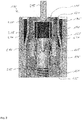
- Fig. 1 shows a fuel injector 100 for injecting fuel into a combustion engine, especially in a power train of a motor vehicle.
- the fuel injector 100 extends along a longitudinal axis 105 and comprises a filter assembly 110 for filtering fuel on its way through the injector 100 between an inlet 115 and a tip 120.
- the filter assembly 110 preferably also extends along the longitudinal axis 105.
- a valve 140 for controlling a flow of fuel through the tip 120 and an electromagnetic actuator 145 for operating the valve 140 are provided.
- the actuator 145 may comprise a solenoid 150 and an armature 155. When the solenoid 150 is energized it attracts the armature 155 which is coupled to the valve 140 so that a flow of fuel through the injector 100 is permitted.
- the fuel injector 100 furthermore comprises a body 125, a cover 130 and a block 135.
- the block 135 is in particular a pole piece of the actuator 145 of the fuel injector 100.
- the block 135 is adapted to receive the filter assembly 110 from an axial direction and the filter assembly 110 is preferred to be adapted for press-fitting into the block 135.
- the block 135 has a central bore extending through the block 135 in longitudinal direction and the filter assembly 110 is received in the central bore.
- a calibration spring 160 is be provided for pushing a valve needle 162 of the valve 140 towards a valve seat of the valve 140 in a direction opposite to the attraction force of the solenoid 150 when energized.
- the filter assembly 110 is in contact with the calibration spring 160 on an axial side opposite to the side on which the calibration spring 160 is in contact with the valve needle 162.
- the preloading force of the calibration spring 160 on the valve needle 162 may be adjusted by changing the axial position of filter assembly 110 with respect to block 135. Through this, dynamic flow characteristics of the injector 100 may be calibrated. Such calibration may be performed during manufacturing the injector 100.
- the filter assembly 110 comprises a filter element 165, a filter housing 170 and, in a preferred embodiment, a filter cap 175.
- the filter element 165 has a cylindrical frame 180, to which a filter screen 185 is attached for filtering fuel which flows through the injector 100 to the valve 140.
- the frame 180 is preferred to be hollow. It may have the shape of a cylinder shell. In other, preferred embodiments the inner lateral surface of the frame 180 is not cylindrical. In this way, a particularly large filtering area of the filter screen 185 is achievable.
- the frame 180 is by preference manufactured from a plastic, in particular by means of moulding or casting.
- the screen 185 may comprise a fine sieve, a fleece or the like. It axially protrudes beyond a first axial end 220 of the frame 180 on a fuel outlet side of the frame 180.
- the screen 185 may be moulded to the frame 180 in the same or a successive process, for example by means of insert moulding.
- the filter housing 170 may be a metal part, for instance manufacturable from a metal sheet by deep-drawing.
- the cap 175 may also comprise a formed sheet metal.
- the cap 175 may be press-fitted onto the filter housing 170. It is preferred that the cap 175 comprises an aperture for permitting a flow of fuel towards the filter element 165. After passing through the filter element 165, the fuel may exit through another aperture in the filter housing 170, near the bottom of filter assembly 110 in Fig. 1 , to flow towards the valve 140.
- Fig. 2 shows the filter assembly 110 during installation in the fuel injector 100 of Fig. 1 .
- a pressing force 205 is exerted to the filter cap 175 from where it may be transferred to the frame 180 of the filter element 165 and on to the filter housing 170.
- the pressing force from the filter cap 175 may be forwarded directly into the filter housing 170 without being conducted axially through the frame 180.
- the pressing force may lie in the range of 200-1000 N or even more.
- the filter housing 170 has a taper 305 where an inner diameter of the filter housing 170 is reduced downstream the filter cap 175.
- the frame 180 has a side wall 218 with a generally cylindrical circumferential outer surface, a first axial end 220 near the taper 305 and a second axial end 225 near the cap 175 (see Fig. 2 ).
- the first axial end 220 is positioned at a fuel outlet side of the frame 180 and the second axial end 225 is positioned at a fuel inlet side of the frame 180.
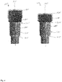
- Fig. 3 shows a filter element 165 and a filter housing 170 of a filter assembly 110 for the injector 100 according to Figs. 1 or 2 in longitudinal section views.
- the first axial end 220 of the cylindrical frame 180 of filter element 165 of filter assembly 110 is shown in detail according to one embodiment.
- the filter housing 170 with a taper 305 for supporting the axial end 220 of the frame 180 is shown in one embodiment. Only the portion of the filter housing 170 on the right hand side of the longitudinal axis 105 is shown for the sake of simplicity. Dimensions are not to be regarded true to scale for the sake of better representability and/or understanding and may not match those in Figs. 1 or 2 .
- the filter housing 170 employs a taper 305 to provide a slanted contact surface 310 against which the axial end 220 of frame 180 may rest.
- the slanted contact surface 310 is a portion of the inner circumferential surface of the filter housing 170.
- the taper 305 has the shape of a conic section, based on a cone with an opening angle ⁇ which is smaller than 180°. This makes it different from a shoulder, which may be understood as a taper based on a cone with an opening angle of 180°.
- An extension of contact surface 310 in an axial direction is marked as y.
- the frame 180 may have a first chamfer 315 at its first axial end 220 to match with the contact surface 310 of the filter housing 170.
- the first chamfer 315 creates a first section 320 of the outer circumferential surface of the sidewall 218 of the frame 180 which also has the shape of a conic section, based on a cone with an opening angle ⁇ . In this, ⁇ is smaller than 180°.
- An extension of the first surface 320 in axial direction is given as h.
- the first section 320 and the contact surface 310 have the same cone angle, i.e. ⁇ may equal ⁇ .
- the second section 330 may also be a second chamfer 325, creating a second section 330 of the outer circumferential surface of the sidewall 218 of the frame 180.
- the second section 330 precedes the first section 320 axially in direction towards the first axial end 220 and, in the present embodiment, has a common interface with the first section 320.
- Both, the first and second sections 320, 330 overlap axially with the taper 305.
- the second section 330 too, has the shape of a conic section, based on a cone with an opening angle of ⁇ .
- ⁇ ⁇ ⁇ ⁇ , and h ⁇ y so that firstly, only a narrow circular section where surfaces 320 and 330 meet at their common interface comes in contact with contact surface 310.
- An accumulated axial height H comprises the axial height h of the first surface 320 and the axial height of the second surface 330.
- Fig. 4 shows exemplary embodiments of the filter assembly 110 of Figs. 1 to 3 .
- the taper 305 there may be further tapers 405 without conflict with the functionality of the first taper 305.
Landscapes
- Engineering & Computer Science (AREA)
- Chemical & Material Sciences (AREA)
- Combustion & Propulsion (AREA)
- Mechanical Engineering (AREA)
- General Engineering & Computer Science (AREA)
- Chemical Kinetics & Catalysis (AREA)
- Manufacturing & Machinery (AREA)
- Fuel-Injection Apparatus (AREA)
- Fuel Cell (AREA)
Claims (8)
- Ensemble de filtre (110) destiné à être utilisé dans un injecteur de carburant (100) pour injecter du carburant dans un moteur à combustion, l'ensemble (110) comprenant :un élément filtre (165) avec un cadre (180), le cadre (180) ayant une extrémité axiale (220) ;un boîtier de filtre tubulaire (170) recevant l'élément filtre (165) ;le boîtier de filtre (170) ayant une paroi latérale avec un cône (305) supportant l'extrémité axiale (220) du cadre (180) de l'élément filtre (165),le cône (305) ayant la forme d'une section conique, basée sur un cône avec un angle d'ouverture γ inférieur à 180° caractérisé en ce queune surface circonférentielle externe du cadre (180) comprend une première section (320) adjacente à ladite extrémité axiale (220) dans la région du cône (305), la première section (320) ayant la forme d'une section conique, basée sur un cône avec un angle d'ouverture α inférieur à 180°.
- Ensemble de filtre (110) selon la revendication 1, dans lequel 60° < α < 160°.
- Ensemble de filtre (110) selon l'une des revendications précédentes, la surface circonférentielle extérieure du cadre (180) comprenant en outre une seconde section (330) dans la région du cône (305), la seconde section (330) ayant la forme d'une section conique, basée sur un cône avec un angle d'ouverture β inférieur à 180° et α ≠ β.
- Ensemble de filtre (110) selon la revendication précédente, dans lequel

- Ensemble de filtre (110) selon la revendication 3 ou 4, dans lequel α > γ > β.
- Ensemble de filtre (110) selon l'une des revendications précédentes, dans lequel h ≤ y ≤ H, avech := une hauteur axiale de la première section (320)y := une hauteur axiale du cône (305) etH := une hauteur axiale accumulée des première et seconde sections (320, 330).
- Ensemble de filtre (110) selon l'une des revendications précédentes, l'ensemble de filtre (110) étant conçu pour être monté par pression de façon axiale dans l'injecteur (100).
- Injecteur de fluide (100) comprenant un ensemble de filtre (110) selon l'une des revendications précédentes.
Priority Applications (5)
| Application Number | Priority Date | Filing Date | Title |
|---|---|---|---|
| EP14155909.6A EP2910770B1 (fr) | 2014-02-20 | 2014-02-20 | Ensemble de filtre et injecteur de carburant |
| PCT/EP2015/052649 WO2015124452A1 (fr) | 2014-02-20 | 2015-02-09 | Ensemble filtre et injecteur de carburant |
| US15/120,636 US10563631B2 (en) | 2014-02-20 | 2015-02-09 | Filter assembly and fuel injector |
| KR1020167025396A KR101908831B1 (ko) | 2014-02-20 | 2015-02-09 | 필터 조립체 및 연료 인젝터 |
| CN201580009591.1A CN106460759B (zh) | 2014-02-20 | 2015-02-09 | 过滤器组件和燃料喷射器 |
Applications Claiming Priority (1)
| Application Number | Priority Date | Filing Date | Title |
|---|---|---|---|
| EP14155909.6A EP2910770B1 (fr) | 2014-02-20 | 2014-02-20 | Ensemble de filtre et injecteur de carburant |
Publications (2)
| Publication Number | Publication Date |
|---|---|
| EP2910770A1 EP2910770A1 (fr) | 2015-08-26 |
| EP2910770B1 true EP2910770B1 (fr) | 2018-09-19 |
Family
ID=50137531
Family Applications (1)
| Application Number | Title | Priority Date | Filing Date |
|---|---|---|---|
| EP14155909.6A Active EP2910770B1 (fr) | 2014-02-20 | 2014-02-20 | Ensemble de filtre et injecteur de carburant |
Country Status (5)
| Country | Link |
|---|---|
| US (1) | US10563631B2 (fr) |
| EP (1) | EP2910770B1 (fr) |
| KR (1) | KR101908831B1 (fr) |
| CN (1) | CN106460759B (fr) |
| WO (1) | WO2015124452A1 (fr) |
Families Citing this family (3)
| Publication number | Priority date | Publication date | Assignee | Title |
|---|---|---|---|---|
| EP2910770B1 (fr) | 2014-02-20 | 2018-09-19 | Continental Automotive GmbH | Ensemble de filtre et injecteur de carburant |
| USD934298S1 (en) | 2020-01-29 | 2021-10-26 | Caterpillar Inc. | Injector |
| USD934299S1 (en) * | 2020-01-29 | 2021-10-26 | Caterpillar Inc. | Injector |
Family Cites Families (11)
| Publication number | Priority date | Publication date | Assignee | Title |
|---|---|---|---|---|
| DE19631280A1 (de) | 1996-08-02 | 1998-02-05 | Bosch Gmbh Robert | Brennstoffeinspritzventil und Verfahren zur Herstellung |
| US6328232B1 (en) | 2000-01-19 | 2001-12-11 | Delphi Technologies, Inc. | Fuel injector spring force calibration tube with internally mounted fuel inlet filter |
| US6554139B1 (en) * | 2000-06-01 | 2003-04-29 | Parker-Hannifin Corporation | Extension and locking assembly for dripless element, and container therefore |
| US6543707B2 (en) * | 2000-12-29 | 2003-04-08 | Siemens Automotive Corporation | Modular fuel injector having a lift set sleeve |
| US6648247B2 (en) * | 2001-02-02 | 2003-11-18 | Siemens Automotive Corporation | Combined filter and adjuster for a fuel injector |
| DE60238813D1 (de) * | 2001-09-19 | 2011-02-17 | Filtertek Inc | Integrierter Kraftstofffilter und Kalibrierungsrohr für ein Kraftstoffeinspritzventil |
| JP3975352B2 (ja) * | 2002-10-30 | 2007-09-12 | 株式会社デンソー | 噴射装置の動的流量調整方法 |
| JP2007500822A (ja) * | 2003-06-10 | 2007-01-18 | シーメンス ヴィディーオー オートモティヴ コーポレイション | 双極磁気回路を有するモジュラー燃料噴射装置 |
| US7128281B2 (en) * | 2004-06-03 | 2006-10-31 | Siemens Vdo Automotive Corporation | Modular fuel injector with a damper member and method of reducing noise |
| EP2000662B1 (fr) | 2007-06-04 | 2012-03-14 | Continental Automotive GmbH | Réglage et agencement de filtre pour soupape d'injection, et soupape d'injection |
| EP2910770B1 (fr) | 2014-02-20 | 2018-09-19 | Continental Automotive GmbH | Ensemble de filtre et injecteur de carburant |
-
2014
- 2014-02-20 EP EP14155909.6A patent/EP2910770B1/fr active Active
-
2015
- 2015-02-09 US US15/120,636 patent/US10563631B2/en active Active
- 2015-02-09 CN CN201580009591.1A patent/CN106460759B/zh active Active
- 2015-02-09 KR KR1020167025396A patent/KR101908831B1/ko active Active
- 2015-02-09 WO PCT/EP2015/052649 patent/WO2015124452A1/fr not_active Ceased
Non-Patent Citations (1)
| Title |
|---|
| None * |
Also Published As
| Publication number | Publication date |
|---|---|
| US10563631B2 (en) | 2020-02-18 |
| US20170009724A1 (en) | 2017-01-12 |
| CN106460759A (zh) | 2017-02-22 |
| EP2910770A1 (fr) | 2015-08-26 |
| KR101908831B1 (ko) | 2018-12-19 |
| WO2015124452A1 (fr) | 2015-08-27 |
| CN106460759B (zh) | 2020-08-11 |
| KR20160122243A (ko) | 2016-10-21 |
Similar Documents
| Publication | Publication Date | Title |
|---|---|---|
| EP2000662A1 (fr) | Réglage et agencement de filtre pour soupape d'injection, et soupape d'injection | |
| EP2771562B1 (fr) | Ensemble de soupape pour soupape d'injection et soupape d'injection | |
| CN105275695B (zh) | 燃料喷射器 | |
| WO1991011611A2 (fr) | Soupape a commande electromagnetique | |
| US10753332B2 (en) | Fuel injector having a throttle element | |
| EP2910770B1 (fr) | Ensemble de filtre et injecteur de carburant | |
| US9038604B2 (en) | Electromagnetically actuable valve | |
| US9885332B2 (en) | Filter assembly for a fuel injector | |
| JPH05502491A (ja) | 電磁的に作動する燃料噴射弁 | |
| EP0659235B1 (fr) | Soupape d'injection de carburant commandee electromagnetiquement | |
| EP2305993A1 (fr) | Soupape d'injection de carburant | |
| DE102011087005A1 (de) | Ventil zum Zumessen eines strömenden Mediums | |
| WO2013029758A1 (fr) | Pompe électromagnétique | |
| EP3279462B1 (fr) | Ensemble filtre pour une soupape d'injection, ensemble de soupapes et soupape d'injection | |
| JP2005233048A (ja) | 流体噴射弁 | |
| JP2550127B2 (ja) | 電磁式燃料噴射弁 | |
| EP1806497A1 (fr) | Injecteur | |
| EP2466109A1 (fr) | Ensemble de soupape pour soupape d'injection et soupape d'injection | |
| DE102010064273A1 (de) | Brennstoffeinspritzventil | |
| JP4432919B2 (ja) | 燃料噴射弁 | |
| EP3359803B1 (fr) | Ensemble de soupape pour soupape d'injection, une telle soupape et procédé pour assembler ladite soupape | |
| JP4178408B2 (ja) | 燃料噴射弁およびその製造方法 |
Legal Events
| Date | Code | Title | Description |
|---|---|---|---|
| PUAI | Public reference made under article 153(3) epc to a published international application that has entered the european phase |
Free format text: ORIGINAL CODE: 0009012 |
|
| AK | Designated contracting states |
Kind code of ref document: A1 Designated state(s): AL AT BE BG CH CY CZ DE DK EE ES FI FR GB GR HR HU IE IS IT LI LT LU LV MC MK MT NL NO PL PT RO RS SE SI SK SM TR |
|
| AX | Request for extension of the european patent |
Extension state: BA ME |
|
| 17P | Request for examination filed |
Effective date: 20160226 |
|
| RBV | Designated contracting states (corrected) |
Designated state(s): AL AT BE BG CH CY CZ DE DK EE ES FI FR GB GR HR HU IE IS IT LI LT LU LV MC MK MT NL NO PL PT RO RS SE SI SK SM TR |
|
| REG | Reference to a national code |
Ref country code: DE Ref legal event code: R079 Ref document number: 602014032408 Country of ref document: DE Free format text: PREVIOUS MAIN CLASS: F02M0061160000 Ipc: B01D0035000000 |
|
| GRAP | Despatch of communication of intention to grant a patent |
Free format text: ORIGINAL CODE: EPIDOSNIGR1 |
|
| STAA | Information on the status of an ep patent application or granted ep patent |
Free format text: STATUS: GRANT OF PATENT IS INTENDED |
|
| RIC1 | Information provided on ipc code assigned before grant |
Ipc: B01D 35/00 20060101AFI20180329BHEP Ipc: B01D 29/31 20060101ALI20180329BHEP Ipc: F02M 61/16 20060101ALI20180329BHEP Ipc: B01D 35/30 20060101ALI20180329BHEP |
|
| INTG | Intention to grant announced |
Effective date: 20180419 |
|
| GRAS | Grant fee paid |
Free format text: ORIGINAL CODE: EPIDOSNIGR3 |
|
| GRAA | (expected) grant |
Free format text: ORIGINAL CODE: 0009210 |
|
| STAA | Information on the status of an ep patent application or granted ep patent |
Free format text: STATUS: THE PATENT HAS BEEN GRANTED |
|
| AK | Designated contracting states |
Kind code of ref document: B1 Designated state(s): AL AT BE BG CH CY CZ DE DK EE ES FI FR GB GR HR HU IE IS IT LI LT LU LV MC MK MT NL NO PL PT RO RS SE SI SK SM TR |
|
| REG | Reference to a national code |
Ref country code: GB Ref legal event code: FG4D |
|
| REG | Reference to a national code |
Ref country code: CH Ref legal event code: EP |
|
| REG | Reference to a national code |
Ref country code: AT Ref legal event code: REF Ref document number: 1042573 Country of ref document: AT Kind code of ref document: T Effective date: 20181015 |
|
| REG | Reference to a national code |
Ref country code: IE Ref legal event code: FG4D |
|
| REG | Reference to a national code |
Ref country code: DE Ref legal event code: R096 Ref document number: 602014032408 Country of ref document: DE |
|
| REG | Reference to a national code |
Ref country code: NL Ref legal event code: MP Effective date: 20180919 |
|
| PG25 | Lapsed in a contracting state [announced via postgrant information from national office to epo] |
Ref country code: FI Free format text: LAPSE BECAUSE OF FAILURE TO SUBMIT A TRANSLATION OF THE DESCRIPTION OR TO PAY THE FEE WITHIN THE PRESCRIBED TIME-LIMIT Effective date: 20180919 Ref country code: SE Free format text: LAPSE BECAUSE OF FAILURE TO SUBMIT A TRANSLATION OF THE DESCRIPTION OR TO PAY THE FEE WITHIN THE PRESCRIBED TIME-LIMIT Effective date: 20180919 Ref country code: LT Free format text: LAPSE BECAUSE OF FAILURE TO SUBMIT A TRANSLATION OF THE DESCRIPTION OR TO PAY THE FEE WITHIN THE PRESCRIBED TIME-LIMIT Effective date: 20180919 Ref country code: GR Free format text: LAPSE BECAUSE OF FAILURE TO SUBMIT A TRANSLATION OF THE DESCRIPTION OR TO PAY THE FEE WITHIN THE PRESCRIBED TIME-LIMIT Effective date: 20181220 Ref country code: RS Free format text: LAPSE BECAUSE OF FAILURE TO SUBMIT A TRANSLATION OF THE DESCRIPTION OR TO PAY THE FEE WITHIN THE PRESCRIBED TIME-LIMIT Effective date: 20180919 Ref country code: NO Free format text: LAPSE BECAUSE OF FAILURE TO SUBMIT A TRANSLATION OF THE DESCRIPTION OR TO PAY THE FEE WITHIN THE PRESCRIBED TIME-LIMIT Effective date: 20181219 Ref country code: BG Free format text: LAPSE BECAUSE OF FAILURE TO SUBMIT A TRANSLATION OF THE DESCRIPTION OR TO PAY THE FEE WITHIN THE PRESCRIBED TIME-LIMIT Effective date: 20181219 |
|
| REG | Reference to a national code |
Ref country code: LT Ref legal event code: MG4D |
|
| PG25 | Lapsed in a contracting state [announced via postgrant information from national office to epo] |
Ref country code: AL Free format text: LAPSE BECAUSE OF FAILURE TO SUBMIT A TRANSLATION OF THE DESCRIPTION OR TO PAY THE FEE WITHIN THE PRESCRIBED TIME-LIMIT Effective date: 20180919 Ref country code: HR Free format text: LAPSE BECAUSE OF FAILURE TO SUBMIT A TRANSLATION OF THE DESCRIPTION OR TO PAY THE FEE WITHIN THE PRESCRIBED TIME-LIMIT Effective date: 20180919 Ref country code: LV Free format text: LAPSE BECAUSE OF FAILURE TO SUBMIT A TRANSLATION OF THE DESCRIPTION OR TO PAY THE FEE WITHIN THE PRESCRIBED TIME-LIMIT Effective date: 20180919 |
|
| REG | Reference to a national code |
Ref country code: AT Ref legal event code: MK05 Ref document number: 1042573 Country of ref document: AT Kind code of ref document: T Effective date: 20180919 |
|
| PG25 | Lapsed in a contracting state [announced via postgrant information from national office to epo] |
Ref country code: AT Free format text: LAPSE BECAUSE OF FAILURE TO SUBMIT A TRANSLATION OF THE DESCRIPTION OR TO PAY THE FEE WITHIN THE PRESCRIBED TIME-LIMIT Effective date: 20180919 Ref country code: NL Free format text: LAPSE BECAUSE OF FAILURE TO SUBMIT A TRANSLATION OF THE DESCRIPTION OR TO PAY THE FEE WITHIN THE PRESCRIBED TIME-LIMIT Effective date: 20180919 Ref country code: IS Free format text: LAPSE BECAUSE OF FAILURE TO SUBMIT A TRANSLATION OF THE DESCRIPTION OR TO PAY THE FEE WITHIN THE PRESCRIBED TIME-LIMIT Effective date: 20190119 Ref country code: PL Free format text: LAPSE BECAUSE OF FAILURE TO SUBMIT A TRANSLATION OF THE DESCRIPTION OR TO PAY THE FEE WITHIN THE PRESCRIBED TIME-LIMIT Effective date: 20180919 Ref country code: EE Free format text: LAPSE BECAUSE OF FAILURE TO SUBMIT A TRANSLATION OF THE DESCRIPTION OR TO PAY THE FEE WITHIN THE PRESCRIBED TIME-LIMIT Effective date: 20180919 Ref country code: ES Free format text: LAPSE BECAUSE OF FAILURE TO SUBMIT A TRANSLATION OF THE DESCRIPTION OR TO PAY THE FEE WITHIN THE PRESCRIBED TIME-LIMIT Effective date: 20180919 Ref country code: CZ Free format text: LAPSE BECAUSE OF FAILURE TO SUBMIT A TRANSLATION OF THE DESCRIPTION OR TO PAY THE FEE WITHIN THE PRESCRIBED TIME-LIMIT Effective date: 20180919 Ref country code: RO Free format text: LAPSE BECAUSE OF FAILURE TO SUBMIT A TRANSLATION OF THE DESCRIPTION OR TO PAY THE FEE WITHIN THE PRESCRIBED TIME-LIMIT Effective date: 20180919 |
|
| PG25 | Lapsed in a contracting state [announced via postgrant information from national office to epo] |
Ref country code: SM Free format text: LAPSE BECAUSE OF FAILURE TO SUBMIT A TRANSLATION OF THE DESCRIPTION OR TO PAY THE FEE WITHIN THE PRESCRIBED TIME-LIMIT Effective date: 20180919 Ref country code: PT Free format text: LAPSE BECAUSE OF FAILURE TO SUBMIT A TRANSLATION OF THE DESCRIPTION OR TO PAY THE FEE WITHIN THE PRESCRIBED TIME-LIMIT Effective date: 20190119 Ref country code: SK Free format text: LAPSE BECAUSE OF FAILURE TO SUBMIT A TRANSLATION OF THE DESCRIPTION OR TO PAY THE FEE WITHIN THE PRESCRIBED TIME-LIMIT Effective date: 20180919 |
|
| REG | Reference to a national code |
Ref country code: DE Ref legal event code: R097 Ref document number: 602014032408 Country of ref document: DE |
|
| PLBE | No opposition filed within time limit |
Free format text: ORIGINAL CODE: 0009261 |
|
| STAA | Information on the status of an ep patent application or granted ep patent |
Free format text: STATUS: NO OPPOSITION FILED WITHIN TIME LIMIT |
|
| PG25 | Lapsed in a contracting state [announced via postgrant information from national office to epo] |
Ref country code: DK Free format text: LAPSE BECAUSE OF FAILURE TO SUBMIT A TRANSLATION OF THE DESCRIPTION OR TO PAY THE FEE WITHIN THE PRESCRIBED TIME-LIMIT Effective date: 20180919 |
|
| 26N | No opposition filed |
Effective date: 20190620 |
|
| REG | Reference to a national code |
Ref country code: CH Ref legal event code: PL |
|
| PG25 | Lapsed in a contracting state [announced via postgrant information from national office to epo] |
Ref country code: SI Free format text: LAPSE BECAUSE OF FAILURE TO SUBMIT A TRANSLATION OF THE DESCRIPTION OR TO PAY THE FEE WITHIN THE PRESCRIBED TIME-LIMIT Effective date: 20180919 Ref country code: MC Free format text: LAPSE BECAUSE OF FAILURE TO SUBMIT A TRANSLATION OF THE DESCRIPTION OR TO PAY THE FEE WITHIN THE PRESCRIBED TIME-LIMIT Effective date: 20180919 Ref country code: LU Free format text: LAPSE BECAUSE OF NON-PAYMENT OF DUE FEES Effective date: 20190220 |
|
| REG | Reference to a national code |
Ref country code: BE Ref legal event code: MM Effective date: 20190228 |
|
| REG | Reference to a national code |
Ref country code: IE Ref legal event code: MM4A |
|
| PG25 | Lapsed in a contracting state [announced via postgrant information from national office to epo] |
Ref country code: CH Free format text: LAPSE BECAUSE OF NON-PAYMENT OF DUE FEES Effective date: 20190228 Ref country code: LI Free format text: LAPSE BECAUSE OF NON-PAYMENT OF DUE FEES Effective date: 20190228 |
|
| PG25 | Lapsed in a contracting state [announced via postgrant information from national office to epo] |
Ref country code: IE Free format text: LAPSE BECAUSE OF NON-PAYMENT OF DUE FEES Effective date: 20190220 |
|
| PG25 | Lapsed in a contracting state [announced via postgrant information from national office to epo] |
Ref country code: BE Free format text: LAPSE BECAUSE OF NON-PAYMENT OF DUE FEES Effective date: 20190228 |
|
| PG25 | Lapsed in a contracting state [announced via postgrant information from national office to epo] |
Ref country code: TR Free format text: LAPSE BECAUSE OF FAILURE TO SUBMIT A TRANSLATION OF THE DESCRIPTION OR TO PAY THE FEE WITHIN THE PRESCRIBED TIME-LIMIT Effective date: 20180919 |
|
| REG | Reference to a national code |
Ref country code: DE Ref legal event code: R081 Ref document number: 602014032408 Country of ref document: DE Owner name: VITESCO TECHNOLOGIES GMBH, DE Free format text: FORMER OWNER: CONTINENTAL AUTOMOTIVE GMBH, 30165 HANNOVER, DE |
|
| PG25 | Lapsed in a contracting state [announced via postgrant information from national office to epo] |
Ref country code: MT Free format text: LAPSE BECAUSE OF NON-PAYMENT OF DUE FEES Effective date: 20190220 |
|
| PG25 | Lapsed in a contracting state [announced via postgrant information from national office to epo] |
Ref country code: CY Free format text: LAPSE BECAUSE OF FAILURE TO SUBMIT A TRANSLATION OF THE DESCRIPTION OR TO PAY THE FEE WITHIN THE PRESCRIBED TIME-LIMIT Effective date: 20180919 |
|
| PG25 | Lapsed in a contracting state [announced via postgrant information from national office to epo] |
Ref country code: HU Free format text: LAPSE BECAUSE OF FAILURE TO SUBMIT A TRANSLATION OF THE DESCRIPTION OR TO PAY THE FEE WITHIN THE PRESCRIBED TIME-LIMIT; INVALID AB INITIO Effective date: 20140220 |
|
| REG | Reference to a national code |
Ref country code: DE Ref legal event code: R081 Ref document number: 602014032408 Country of ref document: DE Owner name: SCHAEFFLER TECHNOLOGIES AG & CO. KG, DE Free format text: FORMER OWNER: VITESCO TECHNOLOGIES GMBH, 30165 HANNOVER, DE Ref country code: DE Ref legal event code: R081 Ref document number: 602014032408 Country of ref document: DE Owner name: VITESCO TECHNOLOGIES GMBH, DE Free format text: FORMER OWNER: VITESCO TECHNOLOGIES GMBH, 30165 HANNOVER, DE |
|
| REG | Reference to a national code |
Ref country code: DE Ref legal event code: R084 Ref document number: 602014032408 Country of ref document: DE |
|
| PG25 | Lapsed in a contracting state [announced via postgrant information from national office to epo] |
Ref country code: MK Free format text: LAPSE BECAUSE OF FAILURE TO SUBMIT A TRANSLATION OF THE DESCRIPTION OR TO PAY THE FEE WITHIN THE PRESCRIBED TIME-LIMIT Effective date: 20180919 |
|
| REG | Reference to a national code |
Ref country code: GB Ref legal event code: 732E Free format text: REGISTERED BETWEEN 20230427 AND 20230503 |
|
| P01 | Opt-out of the competence of the unified patent court (upc) registered |
Effective date: 20230530 |
|
| REG | Reference to a national code |
Ref country code: DE Ref legal event code: R081 Ref document number: 602014032408 Country of ref document: DE Owner name: SCHAEFFLER TECHNOLOGIES AG & CO. KG, DE Free format text: FORMER OWNER: VITESCO TECHNOLOGIES GMBH, 93055 REGENSBURG, DE |
|
| PGFP | Annual fee paid to national office [announced via postgrant information from national office to epo] |
Ref country code: GB Payment date: 20260219 Year of fee payment: 13 |
|
| PGFP | Annual fee paid to national office [announced via postgrant information from national office to epo] |
Ref country code: DE Payment date: 20260228 Year of fee payment: 13 |
|
| PGFP | Annual fee paid to national office [announced via postgrant information from national office to epo] |
Ref country code: IT Payment date: 20260224 Year of fee payment: 13 |
|
| PGFP | Annual fee paid to national office [announced via postgrant information from national office to epo] |
Ref country code: FR Payment date: 20260218 Year of fee payment: 13 |