EP3279462B1 - Ensemble filtre pour une soupape d'injection, ensemble de soupapes et soupape d'injection - Google Patents
Ensemble filtre pour une soupape d'injection, ensemble de soupapes et soupape d'injection Download PDFInfo
- Publication number
- EP3279462B1 EP3279462B1 EP16182697.9A EP16182697A EP3279462B1 EP 3279462 B1 EP3279462 B1 EP 3279462B1 EP 16182697 A EP16182697 A EP 16182697A EP 3279462 B1 EP3279462 B1 EP 3279462B1
- Authority
- EP
- European Patent Office
- Prior art keywords
- filter
- assembly
- valve
- cap
- filter assembly
- Prior art date
- Legal status (The legal status is an assumption and is not a legal conclusion. Google has not performed a legal analysis and makes no representation as to the accuracy of the status listed.)
- Active
Links
Images



Classifications
-
- F—MECHANICAL ENGINEERING; LIGHTING; HEATING; WEAPONS; BLASTING
- F02—COMBUSTION ENGINES; HOT-GAS OR COMBUSTION-PRODUCT ENGINE PLANTS
- F02M—SUPPLYING COMBUSTION ENGINES IN GENERAL WITH COMBUSTIBLE MIXTURES OR CONSTITUENTS THEREOF
- F02M61/00—Fuel-injectors not provided for in groups F02M39/00 - F02M57/00 or F02M67/00
- F02M61/16—Details not provided for in, or of interest apart from, the apparatus of groups F02M61/02 - F02M61/14
- F02M61/165—Filtering elements specially adapted in fuel inlets to injector
-
- F—MECHANICAL ENGINEERING; LIGHTING; HEATING; WEAPONS; BLASTING
- F02—COMBUSTION ENGINES; HOT-GAS OR COMBUSTION-PRODUCT ENGINE PLANTS
- F02M—SUPPLYING COMBUSTION ENGINES IN GENERAL WITH COMBUSTIBLE MIXTURES OR CONSTITUENTS THEREOF
- F02M51/00—Fuel-injection apparatus characterised by being operated electrically
- F02M51/06—Injectors peculiar thereto with means directly operating the valve needle
- F02M51/061—Injectors peculiar thereto with means directly operating the valve needle using electromagnetic operating means
- F02M51/0625—Injectors peculiar thereto with means directly operating the valve needle using electromagnetic operating means characterised by arrangement of mobile armatures
- F02M51/0664—Injectors peculiar thereto with means directly operating the valve needle using electromagnetic operating means characterised by arrangement of mobile armatures having a cylindrically or partly cylindrically shaped armature, e.g. entering the winding; having a plate-shaped or undulated armature entering the winding
- F02M51/0671—Injectors peculiar thereto with means directly operating the valve needle using electromagnetic operating means characterised by arrangement of mobile armatures having a cylindrically or partly cylindrically shaped armature, e.g. entering the winding; having a plate-shaped or undulated armature entering the winding the armature having an elongated valve body attached thereto
- F02M51/0682—Injectors peculiar thereto with means directly operating the valve needle using electromagnetic operating means characterised by arrangement of mobile armatures having a cylindrically or partly cylindrically shaped armature, e.g. entering the winding; having a plate-shaped or undulated armature entering the winding the armature having an elongated valve body attached thereto the body being hollow and its interior communicating with the fuel flow
-
- F—MECHANICAL ENGINEERING; LIGHTING; HEATING; WEAPONS; BLASTING
- F02—COMBUSTION ENGINES; HOT-GAS OR COMBUSTION-PRODUCT ENGINE PLANTS
- F02M—SUPPLYING COMBUSTION ENGINES IN GENERAL WITH COMBUSTIBLE MIXTURES OR CONSTITUENTS THEREOF
- F02M51/00—Fuel-injection apparatus characterised by being operated electrically
- F02M51/06—Injectors peculiar thereto with means directly operating the valve needle
- F02M51/061—Injectors peculiar thereto with means directly operating the valve needle using electromagnetic operating means
- F02M51/0625—Injectors peculiar thereto with means directly operating the valve needle using electromagnetic operating means characterised by arrangement of mobile armatures
- F02M51/0664—Injectors peculiar thereto with means directly operating the valve needle using electromagnetic operating means characterised by arrangement of mobile armatures having a cylindrically or partly cylindrically shaped armature, e.g. entering the winding; having a plate-shaped or undulated armature entering the winding
- F02M51/0685—Injectors peculiar thereto with means directly operating the valve needle using electromagnetic operating means characterised by arrangement of mobile armatures having a cylindrically or partly cylindrically shaped armature, e.g. entering the winding; having a plate-shaped or undulated armature entering the winding the armature and the valve being allowed to move relatively to each other or not being attached to each other
-
- F—MECHANICAL ENGINEERING; LIGHTING; HEATING; WEAPONS; BLASTING
- F02—COMBUSTION ENGINES; HOT-GAS OR COMBUSTION-PRODUCT ENGINE PLANTS
- F02M—SUPPLYING COMBUSTION ENGINES IN GENERAL WITH COMBUSTIBLE MIXTURES OR CONSTITUENTS THEREOF
- F02M61/00—Fuel-injectors not provided for in groups F02M39/00 - F02M57/00 or F02M67/00
- F02M61/16—Details not provided for in, or of interest apart from, the apparatus of groups F02M61/02 - F02M61/14
- F02M61/168—Assembling; Disassembling; Manufacturing; Adjusting
-
- F—MECHANICAL ENGINEERING; LIGHTING; HEATING; WEAPONS; BLASTING
- F02—COMBUSTION ENGINES; HOT-GAS OR COMBUSTION-PRODUCT ENGINE PLANTS
- F02M—SUPPLYING COMBUSTION ENGINES IN GENERAL WITH COMBUSTIBLE MIXTURES OR CONSTITUENTS THEREOF
- F02M2200/00—Details of fuel-injection apparatus, not otherwise provided for
- F02M2200/50—Arrangements of springs for valves used in fuel injectors or fuel injection pumps
Definitions
- the present invention relates to a filter assembly for a fluid injection valve, a valve assembly and a fluid injection valve.
- the fluid injection valve may in particular be an injection valve for injecting fuel into a combustion engine.
- a valve assembly for a fluid injection valve comprises a valve body comprising a cavity with a fluid inlet portion and a fluid outlet portion and a valve needle axially moveable in the cavity.
- the valve needle prevents a fluid flow through the fluid outlet portion in a closing position and releases the fluid flow through the fluid outlet portion in further positions.
- the valve needle may be actuated by an electromagnetic actuation unit.
- a filter assembly is provided at the fluid inlet portion of the valve assembly for filtering the fluid to be dosed.
- Such a filter assembly is shown in EP 2 949 917 A1 .
- the valve needle is biased towards a closing position by a preloaded calibration spring.
- the calibration spring can be preloaded by press-fitting the filter assembly or a adjustment tube located on top of the spring into the housing, the pole piece or another element of the injection valve as disclosed in US 6,997,404 B2 , in DE 10 2013 225 820 A1 and in DE 10 2007 049 963 A1 . This, however, adds to the length of the injector.
- a filter assembly for a fluid injection valve having a fluid inlet portion and a fluid outlet portion, wherein at least one flow path for fluid flow with a flow direction is formed between the fluid inlet portion and the fluid outlet portion.
- the filter assembly comprises a filter sleeve having a first part and a second part.
- the first part comprises a filter element.
- the second part is arranged downstream of the first part with respect to the flow direction and forms a receptacle for an upper part of a calibration spring of the fluid injection valve, wherein a circumferential side wall of the receptacle is arranged to surround the upper part of the calibration spring.
- the area, where the element preloading the calibration spring and an element of the valve assembly, e.g. the pole piece, are in frictional contact with one another, does not extend upwards from the calibration spring but around its upper part or some distance downwards from the upper part, i.e. some distance towards its lower part.
- the clamping area of the calibration spring is moved from above the spring to the spring area itself.
- the receptacle comprises a ledge for supporting the calibration spring, the ledge protruding from the circumferential side wall and dividing the first part from the second part.
- the ledge provides support for the calibration spring.
- the ledge can be formed integrally with the filter sleeve. It protrudes from the circumferential side wall far enough to allow for a stable support of the calibration spring.
- the ledge makes an annular support for the calibration spring, which is typically a coil spring.
- the central opening of this annular support makes a passage for fluid flow.
- the second part of the filter sleeve has, on an outer surface of the circumferential side wall, a first fitting area for press-fitting the filter assembly into a fuel injector.
- a fitting area is hereby understood to be a contact area between e.g. two elements, where frictional forces between the two elements make a frictional locking connection between the two elements.
- the dimensions of the filter sleeve are chosen accordingly. In particular the diameter of the filter sleeve is chosen to make press-fitting the filter sleeve possible.
- the filter sleeve is made in one piece, i.e. the first part and the second part are formed integrally. This simplifies the manufacture of the filter sleeves and saves costs.
- a disk having at least one opening is arranged in the filter sleeve dividing the first part from the second part and providing a support for the calibration spring.
- the disk can be an annular disk with a central opening or with a number of openings making a passage for fluid flow. This has the advantage, that a dampening effect on pressure waves in the fuel is created.
- the dampening effect and the passage of fuel through the opening are both satisfactory if the opening (in the case of one central opening) has a diameter of 0,5 millimeters to 1 millimeters, more particularly of 0,7 millimeters to 0,9 millimeters.
- the disk can, in particular, be supported by the ledge.
- the outer diameter of the disk is typically chosen to be only slightly smaller than the inner diameter of the filter sleeve but larger than the inner diameter of the ledge.
- the second part of the filter sleeve has, on an inner surface of the circumferential side wall, a spring fitting region for fastening a calibration spring within the filter sleeve.
- the calibration spring may be fixed to the filter sleeve, but the fastening can also mean a guiding of the calibration spring.
- the upper part of the calibration spring can be fitted into the receptacle such that the inner surface of the circumferential side wall having the spring fitting region provides guidance for the calibration spring.
- the inner diameter of the receptacle is only slightly larger than the outer diameter of the calibration spring, and the axial length of the receptacle is sufficient to provide reliable guidance.
- a cap is arranged in the filter sleeve, the cap having a side wall part arranged coaxially with the circumferential side wall of the second part and a disk shaped part with at least one opening, the disk shaped part dividing the first part of the filter sleeve from the second part and providing a support for the calibration spring.
- the receptacle receives the calibration spring and the cap.
- the axial length of the cap is not larger than that of the receptacle so that the cap does not protrude from the receptacle.
- the cap provides a particularly reliable guidance for the calibration spring.
- the cap may, on an inner surface of the side wall part, have a spring fitting region for fastening the calibration spring within the cap.
- fastening of the calibration spring may mean securely guiding the calibration spring.
- the cap has, on an outer surface of the side wall part, a cap fitting region for joining the cap to the filter sleeve.
- the cap could be welded to the filter sleeve.
- the cap could be press-fitted into the filter sleeve.
- the outer diameter of the cap and the inner diameter of the filter sleeve are such that a connection between both is possible. This has the advantage, that the cap providing particularly secure guidance of the calibration spring can be inserted into the filter sleeve.
- the filter element comprises a body part which may comprise a plastic material (e.g. Nylon) and is joined to the first part of the filter sleeve, for example by welding or press-fitting.
- the filter element further comprises a cap part comprising a metal and being joined to a fluid inlet portion of the filter element, for example by welding or press-fitting.
- the cap part may have one or more openings to make a passage for fluid flow. The diameter of the openings may be relatively small to provide a dampening effect on pressure waves.
- the filter assembly can comprise a different type of filter element.
- the filter element is formed by the first part of the filter sleeve comprising a number of through-holes forming the fluid inlet portion of the filter assembly.
- the first part of the filter sleeve is closed at its upper end and provided with through holes, which may e.g. be laser-drilled, electron beam-drilled or drilled mechanically.
- the first part of the filter sleeve constitutes the filter element.
- the filter sleeve and/or the cap comprise steel, particularly stainless steel, and/or a copper alloy. These materials have the necessary corrosion resistance and provide the suitable mechanical properties for a tight press-fit.
- the filter sleeve and/or the cap can be manufactured by a deep-drawing process.
- a valve assembly for an injection valve comprising a valve body comprising a cavity with a fluid inlet portion and a fluid outlet portion, a valve needle axially moveable in the cavity, the valve needle preventing a fluid flow through the fluid outlet portion in a closing position and releasing the fluid flow through the fluid outlet portion in further positions.
- the valve assembly further comprises the described filter assembly and a preloaded calibration spring for biasing the valve needle, the calibration spring having a lower part which is allocated near one end of the valve needle and an upper part which is allocated at a distance from the needle, the upper part being received by the receptacle.
- the circumferential side wall of the receptacle encloses a plurality of turns of the calibration spring which represent the upper part of the calibration spring.
- the pole piece of the valve assembly provides a rigid element suitable to receive the filter assembly.
- the pole piece typically has a central opening receiving the calibration spring. Into this central opening the spring with the filter assembly may be press-fitted. Thus, the first fitting area of the second part of the filter sleeve is in contact with the pole piece.
- Frictional forces between the fitting area of the second part of the filter sleeve and the inner surface of the pole piece make a stable frictional locking connection between the two press-fitted parts.
- a fluid injection valve with the described valve assembly is provided.
- the injection valve has the advantages described above in connection with the filter assembly.
- the fluid injection valve 1 shown in figures 1 to 10 is in particular suitable for dosing fuel to an internal combustion engine.
- the invention could be used in other types of injection valves, too.
- the injection valve 1 comprises a valve assembly 3.
- the valve assembly 3 comprises a valve body 5 with a central longitudinal axis.
- the valve body 5 comprises a cavity 7.
- the cavity 7 has a fluid outlet portion 11.
- the fluid outlet portion 11 communicates with a fluid inlet portion 9 which is provided in the valve body 5.
- the fluid inlet portion 9 and the fluid outlet portion 11 are in particular positioned at opposite axial ends of the valve body 5.
- the cavity 7 takes in a valve needle 13.
- the valve needle 13 comprises a needle shaft 12 and a sealing ball 14 welded to the tip of the needle shaft 12.
- the injection valve 1 comprises an electromagnetic actuator unit 17 for the valve needle 13.
- the actuator unit 17 comprises a solenoid 19, an armature 21 and a pole piece 27.
- the armature 21 is axially movable in the cavity 7.
- the armature 21 is separate from the valve needle 13 and is axially movable relative to the valve needle 13 and to the valve body 5.
- a lower retainer 23 and an upper retainer 25 are fixed to the valve needle 13.
- This type of injector is sometimes called “free-lift” injector, because the armature travels upwards some distance (the free-lift gap) before engaging the needle.
- the invention can be used with different types of injectors, where the armature is fixed to the needle, for example.
- the valve needle 13 is preloaded by a calibration spring 15 which is arranged in the cavity 7 at the end of the valve needle 13 facing the fluid inlet portion 9.
- a lower part 29 of the calibration spring 27 is supported by the upper retainer 25. It could be supported by the valve needle 13 itself, too.
- FIG. 1 An upper part 31 of the calibration spring 27 is received by the receptacle 35 of a filter assembly 33, which is press-fitted with the pole piece 27.
- the receptacle 35 is formed by a circumferential side wall 45 of the filter assembly 33. This is explained in more detail with reference to figures 2 to 10 .
- the embodiment shown in figure 1 is also shown in figure 8 .
- the filter assembly 33 can be moved axially in the valve body 5 in order to preload the calibration spring 15 in a desired manner.
- the calibration spring 15 exerts the desired force on the valve needle 13 towards a fluid outlet portion 11 of the injection valve 1. In the closing position of the valve needle 13, a fluid flow through the fluid outlet portion 11 is prevented.
- the solenoid 19 is energized, the magnetic force on the armature 21 overcomes the force exerted by the calibration spring 15 and the armature 21 moves upwards, taking with it the valve needle 13 by means of the upper retainer 25.
- the fluid outlet portion 11 is opened.
- the calibration spring 15 forces the valve needle 13 downwards towards the fluid outlet portion 11, until the fluid outlet portion 11 is closed by the ball 14.
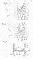
- FIG. 2 shows details of the injection valve 1 according to a first embodiment of the invention.
- the filter assembly 33 comprises a filter sleeve 37, which may be a cylindrical tube and which has a first part 39 near the fluid inlet portion 11 and a second part 41 further away from the fluid inlet portion 11. Thus, the second part 41 is arranged downstream from the first part 39.
- a ledge 47 formed by a protrusion of the sleeve 37 divides the first part 39 from the second part 41.
- the first part 39 comprises a filter element 43, which in this embodiment is formed of the upper part of the filter sleeve 37 being perforated by a number of laser-drilled through-holes. In this embodiment, the upper end of the filter sleeve 37 is closed.
- the second part 41 has a circumferential side wall 45, which forms a receptacle 35 for the upper part 31 of the calibration spring 15.
- the filter sleeve 37 is press-fitted into a central opening in the pole piece 27.
- the outside of the second part 41 is in frictional contact with the inner surface of the pole piece 27.
- the area on the outside of the second part 41, where there is contact between the filter sleeve 37 and the pole piece 27, is the first fitting area 49. Frictional forces operating across this area 49 make a frictional locking connection between the filter assembly 33 and the pole piece 27.
- the calibration spring 15 When the filter assembly 33 is inserted into the central opening in the pole piece 27, the calibration spring 15 is compressed and thereby preloaded.
- the calibration spring 15 is supported by the ledge 47 and received in and guided by the receptacle 35.
- the circumferential side wall 45 functions as a guide for the calibration spring 15.
- FIG. 3 shows details of the injection valve 1 according to a second embodiment of the invention.
- This embodiment differs from the first one only in the kind of filter element 43 used.
- the filter element 43 has a body part 51 made of a plastic material and being press-fitted onto a fluid inlet portion of the filter element 43.
- the filter element 43 further comprises a cap part 53 made of a metal and being press-fitted onto the first part 39 of the filter sleeve 37.
- FIG. 4 shows details of the filter sleeve 37 according to the first and second embodiments .
- the filter sleeve 37 comprises a circumferential ledge 47 which protrudes from the circumferential side wall 45 and forms a support for the calibration spring 15.
- a part of an inner surface of the circumferential side wall 45 serves as a guide for the calibration spring 15. This surface area, where the calibration spring 15 may be in contact with the circumferential side wall 45, is called the spring fitting region.
- Figure 5 shows details of an injection valve 1 according to a third embodiment of the invention.
- This embodiment differs from the first one shown in figure 2 in that an additional disk 55 is arranged below the ledge 47, covering essentially the entire cross-section of the filter sleeve 37 and providing a stable support for the calibration spring 15.
- the disk 55 has a central opening which can be better seen from figure 7 .
- the disk has the advantage that it functions as a throttle for passing fluid, reducing pressure waves.
- FIG. 6 shows details of an injection valve 1 according to a fourth embodiment of the invention. This embodiment differs from the third only in the kind of filter element 43 used. According to the fourth embodiment, a filter element 43 as described above with reference to figure 3 is used.
- Figure 7 shows a detailed view of the filter sleeve 37 with the disk 55 according to the third and fourth embodiments.
- the diameter of the central opening 59 in the disk can be chosen according to the desired throttle effect. Instead of a single central opening, a number of openings could be used.
- Figure 8 shows details of an injection valve 1 according to a fifth embodiment of the invention. This embodiment differs from the first and third one shown in figures 2 and 5 in that a cap 57 is arranged below the ledge 47.
- the cap 57 has a disk shaped part 61 which can be seen in more detail in figure 10 and which essentially corresponds to the disk 55 of the third and fourth embodiment.
- the disk shaped part 61 has at least one opening. It may have one central opening 63 as shown in figure 10 .
- the disk shaped part 61 divides the first part 39 of the filter sleeve 37 from the second part 41 and provides a support for the calibration spring 15.
- the cap 57 further comprises a side wall part 65 arranged coaxially with the circumferential side wall 45 of the second part 41. On an inner surface 69 of the side wall part 65, the cap 57 has a spring fitting region 67 for fastening the calibration spring 15 within the cap 57.
- a cap fitting region 73 for press-fitting the cap 57 into the filter sleeve 37 is defined as the area where frictional forces operate to form a frictional locking connection between the cap 57 and the filter sleeve 37, when the cap 57 is press-fitted into the filter sleeve 37.
- the cap 57 could be welded to the filter sleeve 37.
- FIG. 9 shows details of an injection valve 1 according to a sixth embodiment of the invention. This embodiment differs from the fifth only in the kind of filter element 43 used. According to the sixth embodiment, a filter element 43 as described above with reference to figures 3 and 6 is used.
Landscapes
- Engineering & Computer Science (AREA)
- Chemical & Material Sciences (AREA)
- Combustion & Propulsion (AREA)
- Mechanical Engineering (AREA)
- General Engineering & Computer Science (AREA)
- Physics & Mathematics (AREA)
- Electromagnetism (AREA)
- Manufacturing & Machinery (AREA)
- Fuel-Injection Apparatus (AREA)
Claims (13)
- Ensemble filtre (33) pour une soupape d'injection de fluide (1), l'ensemble filtre (33) ayant une partie d'entrée de fluide et une partie de sortie de fluide, au moins un chemin d'écoulement pour un écoulement de fluide avec une direction d'écoulement étant formé entre la partie d'entrée de fluide et la partie de sortie de fluide, l'ensemble filtre (33) comprenant un manchon de filtre (37) ayant une première partie (39) et une seconde partie (41), la première partie (39) comprenant un élément filtre (43) et la seconde partie (41) étant disposée en aval de la première partie (39) par rapport à la direction d'écoulement et formant un réceptacle (35) pour une partie supérieure (31) d'un ressort de calibrage (15) de la soupape d'injection de fluide (1), une paroi latérale circonférentielle (45) du réceptacle (35) étant disposée pour entourer la partie supérieure (31) du ressort de calibrage (15)
caractérisé en ce que
le manchon de filtre (37) est réalisé d'une seule pièce et a une saillie formant un rebord (47) pour supporter le ressort de calibrage (15), le rebord (47) faisant saillie de la paroi latérale circonférentielle (45) et séparant la première partie (39) de la seconde partie (41)
la seconde partie (41) du manchon de filtre (37) a, sur une surface extérieure de la paroi latérale circonférentielle (45), une première zone de montage (49) pour ajuster avec serrage l'ensemble filtre (33) dans un injecteur de carburant (1). - Ensemble filtre (33) selon la revendication 1,
un disque (55) ayant au moins une ouverture (59) étant disposé dans le manchon de filtre (37) séparant la première partie (39) de la seconde partie (41) et fournissant un support pour le ressort de calibrage (15). - Ensemble filtre (33) selon la revendication 1,
l'ouverture centrale (59) ayant un diamètre de 0,5 millimètre à 1 millimètre, en particulier de 0,7 millimètre à 0,9 millimètre. - Ensemble filtre (33) selon l'une quelconque des revendications 1 à 3,
la seconde partie (41) du manchon de filtre (37) ayant, sur une surface intérieure de la paroi latérale circonférentielle (45), une zone de montage de ressort pour la fixation du ressort de calibrage (15) dans le manchon de filtre (37). - Ensemble filtre (33) selon la revendication 1,
un capuchon étant disposé dans le manchon de filtre (37), le capuchon (57) ayant
une partie de paroi latérale (65) disposée coaxialement à la paroi latérale circonférentielle de la seconde partie (41) et
une pièce en forme de disque (61) avec au moins une ouverture (63), la pièce en forme de disque (61) séparant la première partie (39) du manchon de filtre (37) de la seconde partie (41) et fournissant un support pour le ressort de calibrage (15). - Ensemble filtre (33) selon la revendication 5,
le capuchon (57) ayant, sur une surface intérieure (69) de la partie de paroi latérale (65), une zone de montage de ressort (67) pour fixer un ressort de calibrage (15) dans le capuchon (57) . - Ensemble filtre (33) selon la revendication 5 ou 6,
le capuchon (57) ayant, sur une surface extérieure (71) de la partie de paroi latérale (65), une zone de fixation de capuchon (73) pour relier le capuchon (57) au manchon de filtre (37) . - Ensemble filtre (33) selon l'une quelconque des revendications 1 à 7,
l'élément filtre (43) comprenant
une partie corps (51) reliée à la première partie (39) du manchon de filtre (37) et
une partie capuchon (53) comprenant un métal et étant reliée à une partie d'entrée de fluide de l'élément filtre (43). - Ensemble filtre (33) selon l'une quelconque des revendications 1 à 7,
l'élément filtre (43) étant formé par la première partie (39) du manchon de filtre (37) comprenant un certain nombre de trous traversants formant la partie d'entrée de fluide de l'ensemble filtre (33). - Ensemble filtre (33) selon l'une quelconque des revendications 1 à 8,
le manchon de filtre (37) et/ou le capuchon (57) comprenant de l'acier et/ou un alliage de cuivre et étant fabriqué par emboutissage profond. - Ensemble de soupapes (3) pour une soupape d'injection (1), comprenant
un corps de soupape (5) comprenant une cavité (7) avec une partie d'entrée de fluide (9) et une partie de sortie de fluide (11),
une aiguille de soupape (13) mobile axialement dans la cavité (7), l'aiguille de soupape (13) empêchant un écoulement de fluide à travers la partie de sortie de fluide (11) dans une position de fermeture et libérant l'écoulement de fluide à travers la partie de sortie de fluide (11) dans d'autres positions,
l'ensemble de soupapes (3) comprenant en outreun ensemble filtre (33) selon l'une quelconque des revendications 1 à 10, etun ressort de calibrage précontraint (15) pour solliciter l'aiguille de soupape (13), le ressort de calibrage (15) ayant une partie inférieure (29) qui est associée à proximité d'une extrémité de l'aiguille de soupape (13) et une partie supérieure (31) qui est associée à une distance de l'aiguille de soupape (13), la partie supérieure (31) étant reçue par le réceptacle (35). - Ensemble de soupapes (3) selon la revendication 11,
l'ensemble filtre (33) étant ajusté avec serrage dans une ouverture centrale d'une pièce polaire (27) de l'ensemble de soupapes (3), la première zone de montage (49) de la seconde partie (41) du manchon de filtre (37) étant en contact avec la pièce polaire (27). - Soupape d'injection de fluide (1) avec un ensemble de soupapes (3) selon la revendication 11 ou 12.
Priority Applications (2)
| Application Number | Priority Date | Filing Date | Title |
|---|---|---|---|
| EP16182697.9A EP3279462B8 (fr) | 2016-08-04 | 2016-08-04 | Ensemble filtre pour une soupape d'injection, ensemble de soupapes et soupape d'injection |
| PCT/EP2017/069403 WO2018024714A1 (fr) | 2016-08-04 | 2017-08-01 | Ensemble filtre pour une soupape d'injection, ensemble soupape et soupape d'injection |
Applications Claiming Priority (1)
| Application Number | Priority Date | Filing Date | Title |
|---|---|---|---|
| EP16182697.9A EP3279462B8 (fr) | 2016-08-04 | 2016-08-04 | Ensemble filtre pour une soupape d'injection, ensemble de soupapes et soupape d'injection |
Publications (3)
| Publication Number | Publication Date |
|---|---|
| EP3279462A1 EP3279462A1 (fr) | 2018-02-07 |
| EP3279462B1 true EP3279462B1 (fr) | 2020-05-06 |
| EP3279462B8 EP3279462B8 (fr) | 2020-06-17 |
Family
ID=56571215
Family Applications (1)
| Application Number | Title | Priority Date | Filing Date |
|---|---|---|---|
| EP16182697.9A Active EP3279462B8 (fr) | 2016-08-04 | 2016-08-04 | Ensemble filtre pour une soupape d'injection, ensemble de soupapes et soupape d'injection |
Country Status (2)
| Country | Link |
|---|---|
| EP (1) | EP3279462B8 (fr) |
| WO (1) | WO2018024714A1 (fr) |
Families Citing this family (2)
| Publication number | Priority date | Publication date | Assignee | Title |
|---|---|---|---|---|
| WO2020069726A1 (fr) | 2018-10-02 | 2020-04-09 | Continental Automotive Gmbh | Filtre de réglage pour soupape d'injection de fluide et soupape d'injection de fluide associée |
| FR3099211B1 (fr) | 2019-07-23 | 2022-08-26 | Delphi Tech Ip Ltd | Ensemble combiné de filtration et de calibration |
Family Cites Families (4)
| Publication number | Priority date | Publication date | Assignee | Title |
|---|---|---|---|---|
| US6997404B2 (en) | 2002-06-12 | 2006-02-14 | Delphi Technologies, Inc. | Porous plastic fuel filter for a fuel injector |
| DE102007049963A1 (de) * | 2007-10-18 | 2009-04-23 | Robert Bosch Gmbh | Brennstoffeinspritzventil |
| DE102013225820A1 (de) * | 2013-12-13 | 2015-06-18 | Robert Bosch Gmbh | Brennstoffeinspritzventil |
| EP2949917B1 (fr) * | 2014-05-27 | 2017-01-04 | Continental Automotive GmbH | Injecteur à carburant |
-
2016
- 2016-08-04 EP EP16182697.9A patent/EP3279462B8/fr active Active
-
2017
- 2017-08-01 WO PCT/EP2017/069403 patent/WO2018024714A1/fr not_active Ceased
Non-Patent Citations (1)
| Title |
|---|
| None * |
Also Published As
| Publication number | Publication date |
|---|---|
| EP3279462B8 (fr) | 2020-06-17 |
| WO2018024714A1 (fr) | 2018-02-08 |
| EP3279462A1 (fr) | 2018-02-07 |
Similar Documents
| Publication | Publication Date | Title |
|---|---|---|
| EP2771562B1 (fr) | Ensemble de soupape pour soupape d'injection et soupape d'injection | |
| EP2333297B1 (fr) | Ensemble de soupape pour soupape d'injection et soupape d'injection | |
| US9038604B2 (en) | Electromagnetically actuable valve | |
| EP2246554A1 (fr) | Ensemble de soupape pour soupape d'injection et soupape d'injection | |
| EP3279462B1 (fr) | Ensemble filtre pour une soupape d'injection, ensemble de soupapes et soupape d'injection | |
| EP3339628A1 (fr) | Ensemble de soupape pour soupape d'injection et soupape d'injection | |
| EP3061963A1 (fr) | Ensemble de soupape avec un élément de guidage | |
| EP3464869B1 (fr) | Ensemble de soupape pour soupape d'injection et soupape d'injection | |
| EP2910770B1 (fr) | Ensemble de filtre et injecteur de carburant | |
| US8646749B2 (en) | Electromagnetically actuatable valve | |
| EP3156638B1 (fr) | Injecteur de carburant | |
| EP3344869B1 (fr) | Injecteur pour moteur à combustion | |
| EP3359803B1 (fr) | Ensemble de soupape pour soupape d'injection, une telle soupape et procédé pour assembler ladite soupape | |
| EP3260695A1 (fr) | Ensemble de soupape pour soupape d'injection et soupape d'injection | |
| US20190211786A1 (en) | Valve Assembly for an Injection Valve and Injection Valve | |
| EP3339626A1 (fr) | Ensemble de soupape comprenant une armature avec surfaces de guidage et passages d'écoulement et soupape d'injection | |
| WO2017041979A2 (fr) | Soupape d'injection de fluide |
Legal Events
| Date | Code | Title | Description |
|---|---|---|---|
| PUAI | Public reference made under article 153(3) epc to a published international application that has entered the european phase |
Free format text: ORIGINAL CODE: 0009012 |
|
| STAA | Information on the status of an ep patent application or granted ep patent |
Free format text: STATUS: THE APPLICATION HAS BEEN PUBLISHED |
|
| AK | Designated contracting states |
Kind code of ref document: A1 Designated state(s): AL AT BE BG CH CY CZ DE DK EE ES FI FR GB GR HR HU IE IS IT LI LT LU LV MC MK MT NL NO PL PT RO RS SE SI SK SM TR |
|
| AX | Request for extension of the european patent |
Extension state: BA ME |
|
| STAA | Information on the status of an ep patent application or granted ep patent |
Free format text: STATUS: REQUEST FOR EXAMINATION WAS MADE |
|
| 17P | Request for examination filed |
Effective date: 20180807 |
|
| RBV | Designated contracting states (corrected) |
Designated state(s): AL AT BE BG CH CY CZ DE DK EE ES FI FR GB GR HR HU IE IS IT LI LT LU LV MC MK MT NL NO PL PT RO RS SE SI SK SM TR |
|
| GRAP | Despatch of communication of intention to grant a patent |
Free format text: ORIGINAL CODE: EPIDOSNIGR1 |
|
| STAA | Information on the status of an ep patent application or granted ep patent |
Free format text: STATUS: GRANT OF PATENT IS INTENDED |
|
| RIC1 | Information provided on ipc code assigned before grant |
Ipc: F02M 61/16 20060101ALI20191115BHEP Ipc: F02M 51/06 20060101AFI20191115BHEP |
|
| INTG | Intention to grant announced |
Effective date: 20191204 |
|
| GRAS | Grant fee paid |
Free format text: ORIGINAL CODE: EPIDOSNIGR3 |
|
| GRAA | (expected) grant |
Free format text: ORIGINAL CODE: 0009210 |
|
| STAA | Information on the status of an ep patent application or granted ep patent |
Free format text: STATUS: THE PATENT HAS BEEN GRANTED |
|
| REG | Reference to a national code |
Ref country code: DE Ref legal event code: R081 Ref document number: 602016035558 Country of ref document: DE Owner name: VITESCO TECHNOLOGIES GMBH, DE Free format text: FORMER OWNER: CONTINENTAL AUTOMOTIVE GMBH, 30165 HANNOVER, DE |
|
| AK | Designated contracting states |
Kind code of ref document: B1 Designated state(s): AL AT BE BG CH CY CZ DE DK EE ES FI FR GB GR HR HU IE IS IT LI LT LU LV MC MK MT NL NO PL PT RO RS SE SI SK SM TR |
|
| REG | Reference to a national code |
Ref country code: GB Ref legal event code: FG4D |
|
| RAP2 | Party data changed (patent owner data changed or rights of a patent transferred) |
Owner name: VITESCO TECHNOLOGIES GMBH |
|
| REG | Reference to a national code |
Ref country code: CH Ref legal event code: EP Ref country code: AT Ref legal event code: REF Ref document number: 1267139 Country of ref document: AT Kind code of ref document: T Effective date: 20200515 |
|
| REG | Reference to a national code |
Ref country code: IE Ref legal event code: FG4D |
|
| REG | Reference to a national code |
Ref country code: DE Ref legal event code: R096 Ref document number: 602016035558 Country of ref document: DE |
|
| REG | Reference to a national code |
Ref country code: CH Ref legal event code: PK Free format text: BERICHTIGUNG B8 |
|
| REG | Reference to a national code |
Ref country code: LT Ref legal event code: MG4D |
|
| REG | Reference to a national code |
Ref country code: NL Ref legal event code: MP Effective date: 20200506 |
|
| PG25 | Lapsed in a contracting state [announced via postgrant information from national office to epo] |
Ref country code: IS Free format text: LAPSE BECAUSE OF FAILURE TO SUBMIT A TRANSLATION OF THE DESCRIPTION OR TO PAY THE FEE WITHIN THE PRESCRIBED TIME-LIMIT Effective date: 20200906 Ref country code: PT Free format text: LAPSE BECAUSE OF FAILURE TO SUBMIT A TRANSLATION OF THE DESCRIPTION OR TO PAY THE FEE WITHIN THE PRESCRIBED TIME-LIMIT Effective date: 20200907 Ref country code: FI Free format text: LAPSE BECAUSE OF FAILURE TO SUBMIT A TRANSLATION OF THE DESCRIPTION OR TO PAY THE FEE WITHIN THE PRESCRIBED TIME-LIMIT Effective date: 20200506 Ref country code: SE Free format text: LAPSE BECAUSE OF FAILURE TO SUBMIT A TRANSLATION OF THE DESCRIPTION OR TO PAY THE FEE WITHIN THE PRESCRIBED TIME-LIMIT Effective date: 20200506 Ref country code: LT Free format text: LAPSE BECAUSE OF FAILURE TO SUBMIT A TRANSLATION OF THE DESCRIPTION OR TO PAY THE FEE WITHIN THE PRESCRIBED TIME-LIMIT Effective date: 20200506 Ref country code: NO Free format text: LAPSE BECAUSE OF FAILURE TO SUBMIT A TRANSLATION OF THE DESCRIPTION OR TO PAY THE FEE WITHIN THE PRESCRIBED TIME-LIMIT Effective date: 20200806 Ref country code: GR Free format text: LAPSE BECAUSE OF FAILURE TO SUBMIT A TRANSLATION OF THE DESCRIPTION OR TO PAY THE FEE WITHIN THE PRESCRIBED TIME-LIMIT Effective date: 20200807 |
|
| PG25 | Lapsed in a contracting state [announced via postgrant information from national office to epo] |
Ref country code: BG Free format text: LAPSE BECAUSE OF FAILURE TO SUBMIT A TRANSLATION OF THE DESCRIPTION OR TO PAY THE FEE WITHIN THE PRESCRIBED TIME-LIMIT Effective date: 20200806 Ref country code: LV Free format text: LAPSE BECAUSE OF FAILURE TO SUBMIT A TRANSLATION OF THE DESCRIPTION OR TO PAY THE FEE WITHIN THE PRESCRIBED TIME-LIMIT Effective date: 20200506 Ref country code: RS Free format text: LAPSE BECAUSE OF FAILURE TO SUBMIT A TRANSLATION OF THE DESCRIPTION OR TO PAY THE FEE WITHIN THE PRESCRIBED TIME-LIMIT Effective date: 20200506 Ref country code: HR Free format text: LAPSE BECAUSE OF FAILURE TO SUBMIT A TRANSLATION OF THE DESCRIPTION OR TO PAY THE FEE WITHIN THE PRESCRIBED TIME-LIMIT Effective date: 20200506 |
|
| REG | Reference to a national code |
Ref country code: AT Ref legal event code: MK05 Ref document number: 1267139 Country of ref document: AT Kind code of ref document: T Effective date: 20200506 |
|
| PG25 | Lapsed in a contracting state [announced via postgrant information from national office to epo] |
Ref country code: AL Free format text: LAPSE BECAUSE OF FAILURE TO SUBMIT A TRANSLATION OF THE DESCRIPTION OR TO PAY THE FEE WITHIN THE PRESCRIBED TIME-LIMIT Effective date: 20200506 Ref country code: NL Free format text: LAPSE BECAUSE OF FAILURE TO SUBMIT A TRANSLATION OF THE DESCRIPTION OR TO PAY THE FEE WITHIN THE PRESCRIBED TIME-LIMIT Effective date: 20200506 |
|
| PG25 | Lapsed in a contracting state [announced via postgrant information from national office to epo] |
Ref country code: DK Free format text: LAPSE BECAUSE OF FAILURE TO SUBMIT A TRANSLATION OF THE DESCRIPTION OR TO PAY THE FEE WITHIN THE PRESCRIBED TIME-LIMIT Effective date: 20200506 Ref country code: AT Free format text: LAPSE BECAUSE OF FAILURE TO SUBMIT A TRANSLATION OF THE DESCRIPTION OR TO PAY THE FEE WITHIN THE PRESCRIBED TIME-LIMIT Effective date: 20200506 Ref country code: ES Free format text: LAPSE BECAUSE OF FAILURE TO SUBMIT A TRANSLATION OF THE DESCRIPTION OR TO PAY THE FEE WITHIN THE PRESCRIBED TIME-LIMIT Effective date: 20200506 Ref country code: SM Free format text: LAPSE BECAUSE OF FAILURE TO SUBMIT A TRANSLATION OF THE DESCRIPTION OR TO PAY THE FEE WITHIN THE PRESCRIBED TIME-LIMIT Effective date: 20200506 Ref country code: EE Free format text: LAPSE BECAUSE OF FAILURE TO SUBMIT A TRANSLATION OF THE DESCRIPTION OR TO PAY THE FEE WITHIN THE PRESCRIBED TIME-LIMIT Effective date: 20200506 Ref country code: RO Free format text: LAPSE BECAUSE OF FAILURE TO SUBMIT A TRANSLATION OF THE DESCRIPTION OR TO PAY THE FEE WITHIN THE PRESCRIBED TIME-LIMIT Effective date: 20200506 Ref country code: CZ Free format text: LAPSE BECAUSE OF FAILURE TO SUBMIT A TRANSLATION OF THE DESCRIPTION OR TO PAY THE FEE WITHIN THE PRESCRIBED TIME-LIMIT Effective date: 20200506 |
|
| REG | Reference to a national code |
Ref country code: DE Ref legal event code: R097 Ref document number: 602016035558 Country of ref document: DE |
|
| PG25 | Lapsed in a contracting state [announced via postgrant information from national office to epo] |
Ref country code: PL Free format text: LAPSE BECAUSE OF FAILURE TO SUBMIT A TRANSLATION OF THE DESCRIPTION OR TO PAY THE FEE WITHIN THE PRESCRIBED TIME-LIMIT Effective date: 20200506 Ref country code: SK Free format text: LAPSE BECAUSE OF FAILURE TO SUBMIT A TRANSLATION OF THE DESCRIPTION OR TO PAY THE FEE WITHIN THE PRESCRIBED TIME-LIMIT Effective date: 20200506 |
|
| PLBE | No opposition filed within time limit |
Free format text: ORIGINAL CODE: 0009261 |
|
| STAA | Information on the status of an ep patent application or granted ep patent |
Free format text: STATUS: NO OPPOSITION FILED WITHIN TIME LIMIT |
|
| PG25 | Lapsed in a contracting state [announced via postgrant information from national office to epo] |
Ref country code: MC Free format text: LAPSE BECAUSE OF FAILURE TO SUBMIT A TRANSLATION OF THE DESCRIPTION OR TO PAY THE FEE WITHIN THE PRESCRIBED TIME-LIMIT Effective date: 20200506 |
|
| REG | Reference to a national code |
Ref country code: CH Ref legal event code: PL |
|
| 26N | No opposition filed |
Effective date: 20210209 |
|
| PG25 | Lapsed in a contracting state [announced via postgrant information from national office to epo] |
Ref country code: CH Free format text: LAPSE BECAUSE OF NON-PAYMENT OF DUE FEES Effective date: 20200831 Ref country code: LU Free format text: LAPSE BECAUSE OF NON-PAYMENT OF DUE FEES Effective date: 20200804 Ref country code: LI Free format text: LAPSE BECAUSE OF NON-PAYMENT OF DUE FEES Effective date: 20200831 |
|
| REG | Reference to a national code |
Ref country code: BE Ref legal event code: MM Effective date: 20200831 |
|
| PG25 | Lapsed in a contracting state [announced via postgrant information from national office to epo] |
Ref country code: SI Free format text: LAPSE BECAUSE OF FAILURE TO SUBMIT A TRANSLATION OF THE DESCRIPTION OR TO PAY THE FEE WITHIN THE PRESCRIBED TIME-LIMIT Effective date: 20200506 |
|
| PG25 | Lapsed in a contracting state [announced via postgrant information from national office to epo] |
Ref country code: IE Free format text: LAPSE BECAUSE OF NON-PAYMENT OF DUE FEES Effective date: 20200804 Ref country code: BE Free format text: LAPSE BECAUSE OF NON-PAYMENT OF DUE FEES Effective date: 20200831 |
|
| REG | Reference to a national code |
Ref country code: DE Ref legal event code: R081 Ref document number: 602016035558 Country of ref document: DE Owner name: SCHAEFFLER TECHNOLOGIES AG & CO. KG, DE Free format text: FORMER OWNER: VITESCO TECHNOLOGIES GMBH, 30165 HANNOVER, DE Ref country code: DE Ref legal event code: R081 Ref document number: 602016035558 Country of ref document: DE Owner name: VITESCO TECHNOLOGIES GMBH, DE Free format text: FORMER OWNER: VITESCO TECHNOLOGIES GMBH, 30165 HANNOVER, DE |
|
| PG25 | Lapsed in a contracting state [announced via postgrant information from national office to epo] |
Ref country code: TR Free format text: LAPSE BECAUSE OF FAILURE TO SUBMIT A TRANSLATION OF THE DESCRIPTION OR TO PAY THE FEE WITHIN THE PRESCRIBED TIME-LIMIT Effective date: 20200506 Ref country code: MT Free format text: LAPSE BECAUSE OF FAILURE TO SUBMIT A TRANSLATION OF THE DESCRIPTION OR TO PAY THE FEE WITHIN THE PRESCRIBED TIME-LIMIT Effective date: 20200506 Ref country code: CY Free format text: LAPSE BECAUSE OF FAILURE TO SUBMIT A TRANSLATION OF THE DESCRIPTION OR TO PAY THE FEE WITHIN THE PRESCRIBED TIME-LIMIT Effective date: 20200506 |
|
| PG25 | Lapsed in a contracting state [announced via postgrant information from national office to epo] |
Ref country code: MK Free format text: LAPSE BECAUSE OF FAILURE TO SUBMIT A TRANSLATION OF THE DESCRIPTION OR TO PAY THE FEE WITHIN THE PRESCRIBED TIME-LIMIT Effective date: 20200506 |
|
| P01 | Opt-out of the competence of the unified patent court (upc) registered |
Effective date: 20230530 |
|
| REG | Reference to a national code |
Ref country code: DE Ref legal event code: R081 Ref document number: 602016035558 Country of ref document: DE Owner name: SCHAEFFLER TECHNOLOGIES AG & CO. KG, DE Free format text: FORMER OWNER: VITESCO TECHNOLOGIES GMBH, 93055 REGENSBURG, DE |
|
| PGFP | Annual fee paid to national office [announced via postgrant information from national office to epo] |
Ref country code: DE Payment date: 20250831 Year of fee payment: 10 |
|
| PGFP | Annual fee paid to national office [announced via postgrant information from national office to epo] |
Ref country code: IT Payment date: 20250825 Year of fee payment: 10 |
|
| PGFP | Annual fee paid to national office [announced via postgrant information from national office to epo] |
Ref country code: GB Payment date: 20250821 Year of fee payment: 10 |
|
| PGFP | Annual fee paid to national office [announced via postgrant information from national office to epo] |
Ref country code: FR Payment date: 20250829 Year of fee payment: 10 |