EP2910904A1 - Capteur à chaîne à réluctance et procédé de mesure d'étirement de chaîne - Google Patents
Capteur à chaîne à réluctance et procédé de mesure d'étirement de chaîne Download PDFInfo
- Publication number
- EP2910904A1 EP2910904A1 EP15000167.5A EP15000167A EP2910904A1 EP 2910904 A1 EP2910904 A1 EP 2910904A1 EP 15000167 A EP15000167 A EP 15000167A EP 2910904 A1 EP2910904 A1 EP 2910904A1
- Authority
- EP
- European Patent Office
- Prior art keywords
- chain
- sensor
- reluctance
- yoke
- sensors
- Prior art date
- Legal status (The legal status is an assumption and is not a legal conclusion. Google has not performed a legal analysis and makes no representation as to the accuracy of the status listed.)
- Granted
Links
Images


Classifications
-
- G—PHYSICS
- G01—MEASURING; TESTING
- G01M—TESTING STATIC OR DYNAMIC BALANCE OF MACHINES OR STRUCTURES; TESTING OF STRUCTURES OR APPARATUS, NOT OTHERWISE PROVIDED FOR
- G01M13/00—Testing of machine parts
-
- G—PHYSICS
- G01—MEASURING; TESTING
- G01D—MEASURING NOT SPECIALLY ADAPTED FOR A SPECIFIC VARIABLE; ARRANGEMENTS FOR MEASURING TWO OR MORE VARIABLES NOT COVERED IN A SINGLE OTHER SUBCLASS; TARIFF METERING APPARATUS; MEASURING OR TESTING NOT OTHERWISE PROVIDED FOR
- G01D5/00—Mechanical means for transferring the output of a sensing member; Means for converting the output of a sensing member to another variable where the form or nature of the sensing member does not constrain the means for converting; Transducers not specially adapted for a specific variable
- G01D5/12—Mechanical means for transferring the output of a sensing member; Means for converting the output of a sensing member to another variable where the form or nature of the sensing member does not constrain the means for converting; Transducers not specially adapted for a specific variable using electric or magnetic means
- G01D5/14—Mechanical means for transferring the output of a sensing member; Means for converting the output of a sensing member to another variable where the form or nature of the sensing member does not constrain the means for converting; Transducers not specially adapted for a specific variable using electric or magnetic means influencing the magnitude of a current or voltage
- G01D5/20—Mechanical means for transferring the output of a sensing member; Means for converting the output of a sensing member to another variable where the form or nature of the sensing member does not constrain the means for converting; Transducers not specially adapted for a specific variable using electric or magnetic means influencing the magnitude of a current or voltage by varying inductance, e.g. by a movable armature
- G01D5/2006—Mechanical means for transferring the output of a sensing member; Means for converting the output of a sensing member to another variable where the form or nature of the sensing member does not constrain the means for converting; Transducers not specially adapted for a specific variable using electric or magnetic means influencing the magnitude of a current or voltage by varying inductance, e.g. by a movable armature by influencing the self-induction of one or more coils
- G01D5/2013—Mechanical means for transferring the output of a sensing member; Means for converting the output of a sensing member to another variable where the form or nature of the sensing member does not constrain the means for converting; Transducers not specially adapted for a specific variable using electric or magnetic means influencing the magnitude of a current or voltage by varying inductance, e.g. by a movable armature by influencing the self-induction of one or more coils by a movable ferromagnetic element, e.g. a core
Definitions
- the present invention relates to a chain sensor with at least one coil and to a device for measuring the chain elongation with two chain sensors and a control unit. Furthermore, the invention relates to a method for measuring the chain elongation of a chain with two chain sensors, which are arranged at a distance from each other along the chain.
- Chain drives in particular based on roller chains, are used in industrial applications for drive and transport purposes, with multiple chain strands being often used in various applications.
- a chain drive unit usually comprises an endlessly circulating chain, which is deflected over a plurality of spaced apart sprockets, and a plurality of actuated by the chain or connected to the chain drive or transport elements.
- drive chains are subject to wear due to the relative movement of the individual parts in the chain link as well as other different chain elongation factors, such as inlet elongation, stretching, bearing clearance and bearing wear. These wear and elongation factors result in elongation of the chain and eventually lead to failure of the drive unit.
- the wear of a chain also depends on the drive unit in which it is used, on the loads to which it is subjected and on the environment in which it is operated. Accordingly, the wear of the chain and thus the failure of the drive unit can not be predicted with certainty.
- a suitable method for monitoring the elongation of a rotating drive chain is known from US 5,291,131 known.
- the drive chain here two spaced apart in the longitudinal direction of the chain markers are provided, the position of which is detected during operation of two inductive or optical sensors, which are also arranged at a distance to each other. Via a connected data acquisition, the measured values of the two sensors can be used to determine the circulating speed of the chain as well as the chain elongation.
- the publication EP 1 464 919 A1 describes a similar method for monitoring the wear of a drive chain. For this purpose, two markings made of a magnetic material are provided on opposite sides of the chain, which generate an electrical signal when passing through two inductive sensors.
- the sensors are arranged at a distance from each other on opposite sides of the drive chain, that initially a simultaneous triggering of the sensors is achieved. As soon as there is a time delay between the triggering of the sensors due to the wear elongation of the chain, the wear elongation of the chain can be determined via a positional shift of the sensors.
- Another device for measuring the wear elongation of a drive chain by means of two optical sensors is in the US 7,540,374 B2 described. In this case, the first sensor detects the first chain link of a chain link and a second sensor determines the position and the distance of the second chain link. Furthermore, the distance of a plurality of chain links at two spaced measurement positions can be determined.
- At least one first reluctance sensor is provided, wherein the reluctance sensor has a magnetically conductive yoke body with a center leg and two laterally extending yoke legs, wherein the at least one inductive coil is preferably arranged on the middle leg, each yoke leg is with at least two teeth provided, wherein the teeth of the yoke legs are arranged at a small distance to a chain, and with at least one permanent magnet, preferably at least two permanent magnets each on a Yoke legs and / or arranged on different sides of the at least one coil. Further, it may be useful when using at least two permanent magnets to position them symmetrically to the center leg.
- the arrangement of the reluctance sensor with a relatively small distance on one side of a chain wherein the yoke body can be arranged parallel to the chain straps of the chain and the projections or teeth of the laterally extending yoke legs preferably extend between the link plates, allows the formation of closed magnetic circuits across the reluctance sensor and the chain with a relatively low reluctance, ie, a low magnetic resistance.
- the largely crescent-shaped yoke body for the magnetic field of the forming magnetic circuits can be well-permeable, for example, a soft magnetic iron core with low magnetic resistance, or with minimal reluctance.
- the magnetic circuits induced across the at least one permanent magnet along the lateral yoke legs generate a voltage across the coil, for example, on the center leg of the yoke body, with only one of the closed magnetic circuits being passed substantially across the coil and the other closed magnetic circuit beyond Coil in short circuit over the teeth of the associated yoke leg and the chain is closed.
- the chain sensor is suitable for measuring the relative elongation and / or the speed of the chain.
- the temperature can also be taken into account in order to take account of different temperature levels in the calculation.
- the reluctance chain sensor according to the invention in spite of its simple structure, can be integrated in a simple manner into new production systems and conveyor systems, but can also be retrofitted to existing systems without any effort.
- the chain sensor is both maintenance-free and resistant to water, oil, dirt, high temperatures and aggressive environmental conditions, against which the drive chain itself is resistant.
- reluctance chain sensors are both independent of the type of chain and of labels on the chain. During operation, the chain sensor can automatically detect the drive chain and determine the chain length independently of the speed of the drive chain.
- the use of the chain sensor according to the invention makes it possible to achieve simple wear monitoring of chain-driven conveying and production systems at low costs.
- At least two permanent magnets can be provided, which are preferably arranged on the outer teeth of the yoke legs of the first reluctance sensor.
- the arrangement of the two permanent magnets on the outer teeth of the yoke legs, preferably at the tips of the outer teeth allow in addition to a simple attachment of the permanent magnet to the magnetically conductive yoke body, which is made of a soft magnetic material, for example, a safe transition of the field lines of the closed magnetic Circles on the chain link.
- this arrangement of the at least two permanent magnets prevents an unwanted short circuit of the magnetic circuit via the yoke legs carrying the respective permanent magnets.
- an arrangement of the at least two permanent magnets on the tips of the outer teeth has technical advantages in the formation of the magnetic circuits, however, it may be more appropriate for an operation to arrange the permanent magnets at a distance from the tips or provide an external protection to a Hitting the chain in chain operation to prevent damage to the permanent magnets.
- the two magnets can also be positioned in the region of the lateral yoke legs.
- the permanent magnets arranged on the yoke legs can have an identical polar direction in the direction of the center leg.
- the clear design of the two closed magnetic circuits allows a clear signal at the at least one coil.
- an arrangement of at least one coil on the center leg can be induced on the coil, an AC voltage, since the closed magnetic circuits are alternately and in different directions over the coil.
- the at least one coil may be arranged on one of the teeth of the yoke legs.
- the arrangement of the at least one or more coils on the teeth of the yoke legs allows a simpler manufacture of the reluctance sensor, since the coils can be prefabricated and arranged during assembly only on the teeth of the yoke legs, i. have to be postponed.
- the arrangement of several coils on each one of the teeth of the yoke legs makes it possible to broaden and differentiate the signals of the reluctance chain sensor and thus creates additional possibilities for calculating the relative change in length and / or the speed of the chain.
- a second reluctance sensor is provided, the second reluctance sensor also has a magnetically conductive yoke body with a center leg and two laterally extending yoke leg, each yoke leg is provided with two of the chain facing teeth, the teeth in a small Distance to the chain can be arranged and facing the first reluctance sensor.
- a second reluctance sensor which can be performed without a second coil and without permanent magnets, allows a more uniform, independent of the design of the chain formation of the two closed magnetic circuits, provided that the coil is positioned on the center leg, and a more regular change of the magnetic field flowing through at least one coil, so that a relatively uniform, recurring alternating voltage is applied to the at least one coil as a function of the speed of the chain.
- a second coil can be arranged on the second reluctance sensor, wherein the inductive coils on the first and second reluctance sensor can be connected in parallel or in series.
- the second coil on the reluctance sensor not only amplifies the measurement signal of the chain sensor, but also makes it possible to even out the measurement signal and to reduce measuring errors.
- the second reluctance sensor can also be provided with two permanent magnets, which are each arranged on one of the two laterally extending yoke legs and increase the magnetic fields in the chain sensor.
- a particular embodiment provides that the lateral yoke limbs of the first and second reluctance sensor are each provided with a permanent magnet, wherein the permanent magnets are preferably respectively disposed on the outer teeth of the yoke legs, or at their tips, and wherein the permanent magnets on the yoke legs of the first reluctance sensor have the same polar direction and the permanent magnets on the yoke legs of the second reluctance sensor have a reverse polarity.
- the orientation of the permanent magnets of the first reluctance sensor or of the second reluctance sensor in the same pole direction ensures that the field lines of the two closed magnetic circuits pass in the same direction extend the inner teeth, whereby the mutual influence of the two closed magnetic circuits is kept low.
- the optional second coil on the second reluctance sensor in the same way, but different direction flows through the respective active magnetic circuit and can thus amplify the signal of the at least one coil on the first reluctance sensor and uniform.
- a further embodiment of the reluctance chain sensor according to the invention for a joint chain with a uniform pitch between the chain links provides that the at least one first reluctance sensor is arranged perpendicular to the articulation axis of the chain links on one side of the articulated chain, the teeth of the yoke legs of the first reluctance sensor of the articulated chain are facing.
- the field lines of the two closed magnetic circuits extend perpendicular to the joint axes.
- the vertical arrangement of the first reluctance sensor allows a very small distance between the teeth of the lateral yoke legs and the chain links of the articulated chain, so that the magnetic resistance over this distance is as low as possible.
- a yoke with a low magnetic resistance the two closed magnetic circuits can extend over the yoke and thus their formation of interference by the to make the moving joint chain more independent.
- a variant of the chain sensor according to the invention provides that a second reluctance sensor is provided, which is arranged perpendicular to the hinge axis of the chain links on an opposite side of the link chain, the teeth of the yoke legs of the second reluctance sensor facing the link chain.
- the distance between the associated teeth of the first and second reluctance sensors can be at most 20%, preferably at most 10%, in particular at most 5% greater than the outer diameter of the chain links of the articulated chain.
- the distance of the outer tooth of one yoke leg to the inner tooth of the other yoke leg of the first or second reluctance sensor may be substantially an integral multiple of the pitch of the articulated chain.
- the generation of a uniform AC voltage to the at least one coil of the first reluctance sensor and optionally also to a second coil is possible.
- a tolerance range of ⁇ 10% of the pitch is to be considered for a substantially integer multiple.
- the present invention relates to an apparatus for measuring the chain elongation of a chain having at least two reluctance chain sensors spaced apart along the chain, and to a control unit for receiving and processing the signals of the two chain sensors provided at each chain sensor at least one coil in operation generates an alternating signal of the voltage induced at the coil.
- the chain sensors can easily be arranged on the chain, usually a roller chain, without having to attach tags to the chain itself or having to thread the chain through a sensor.
- the control unit connected to the chain sensors allows in addition to a pure monitoring of the chain elongation or chain wear and the detection of other operating parameters, such as operating hours, and the integration of safety functions, such as an alarm when exceeding a predetermined wear value, a stop function in critical wear conditions, a Protection mode with reduced speed from an increased wear value as well as reliable detection of wear conditions and compensation of chain elongation for relevant components. Furthermore, measured values and control data can be transferred to a central process computer or to production centers via the control unit.
- a particular embodiment of the device provides that at least three chain sensors are provided.
- a third chain sensor makes it possible to always determine the direction of movement of the chain, independently of a distance of the two first reluctance chain sensors exactly matched to the chain pitch.
- a comparator for converting the alternating signals into rectangular signals can be provided for each chain sensor.
- the use of comparators allows via the differentiation of the alternating signal, i. Conversion of the alternating signal into a rectangular signal an exact temporal assignment when all teeth of the yoke body are assigned in the same way, the spaces between the chain links.
- the period of the rectangular signal is inversely proportional to the speed of the chain. Accordingly, the distance of the switching pulses of the two chain sensors in relation to the period can provide a clear measure of the chain length.
- the coil on the center leg of the yoke body is generated during operation of the device by the movement of the chain along the chain sensors on the coil an alternating signal with alternating positive and negative voltage, ie an AC voltage, since the two magnetic circuits of the reluctance sensor alternately in different direction through the coil on the center leg pass.
- these alternating signals can be converted into periodic rectangular signals, wherein the phase change of the AC voltage an exact time assignment of the chain or the chain joints to the square wave signal is possible.
- a particular embodiment of the device for measuring the chain elongation of a chain with two reluctance chain sensors provides that the control unit uses the alternating signals or the alternating voltage for the power supply, preferably for self-sufficient power supply of the device.
- the control unit uses the alternating signals or the alternating voltage for the power supply, preferably for self-sufficient power supply of the device.
- the possibility of self-sufficient power supply of the control unit and associated components for data transmission and visualization of the measurement data allows easy integration of such devices in existing machines and systems without interfering with the usually complex concept of energy supply existing machinery and equipment.
- the condition of a chain operation can also be detected in existing systems at any time and an early warning or automatic synchronization of the system can be made self-sufficient.
- This aspect of the present invention could also enjoy protection independent of the details of the reluctance chain sensors of the invention and the apparatus for measuring the chain elongation and be pursued independently.
- the use of the chain sensors as generators for power supply ensures a self-sufficient operation of appropriate measuring devices.
- a suitable embodiment of the device provides that a display unit is provided for displaying the chain elongation of the chain.
- a display unit In addition to the easy readability of the chain wear length and the operating state of the drive chain, such a display unit also enables the display of other important operating and safety parameters such as operating hours counter, warning functions and error displays.
- the display unit for displaying the chain elongation as well as the control unit via the chain sensors can be supplied independently with the necessary energy to operate the display unit.
- the device may additionally comprise temperature sensors, for example infrared temperature sensors, to determine the actual temperature of the chain and the device.
- temperature sensors for example infrared temperature sensors
- a shock sensor for example an acceleration sensor.
- an acceleration sensor By means of the differences in the measured values, it is possible, for example, to make a statement about the lubricating state and the tilting of chain links of the chain by means of the shock or acceleration spectrum which arises when the chain enters the device on the shock sensor used.
- the monitoring of the chain state by means of a shock sensor or an acceleration sensor is particularly possible that align in a not sufficiently lubricated or heavily worn chain, the chain links and when entering the device different rashes and / or relative acceleration of the respective chain links can generate.
- the present invention further relates to a method for measuring the chain elongation of a chain having at least two reluctance chain sensors, which are arranged at a distance from one another along the chain, wherein each chain sensor has at least one coil and at least one permanent magnet, preferably at least two permanent magnets.
- This method comprises forming two closed permanent magnetic circuits with a low reluctance relative to the magnetic field lines across each chain sensor, wherein the two closed magnetic circuits are each short-circuited over the chain sensor depending on the position of the chain to the chain sensor temporarily one or alternately both of the closed magnetic circuits at least partially flooded the at least one coil and the other of the closed magnetic circuits is further led in short circuit on the chain sensor; Moving the chain in one direction along the two chain sensors; periodic change of the magnetic circuits at least partially passing through the at least one coil; and generating an alternating voltage signal on the coils of the two chain sensors.
- the position of the two closed magnetic circuits in the chain sensors depends on the position of the chain to the sensors, magnetic circuits are formed corresponding to the movement of the chain relative to the chain sensors, which changes their position in the chain sensors depending on the position of the chain. Since the magnetic circuits induced by the permanent magnets tend to close the magnetic flux between the poles of the permanent magnet via a magnetic circuit with the lowest possible magnetic resistance or reluctance, the position of the chain changes with a movement of the chain relative to the chain sensors two magnetic circuits in the chain sensors and thus also their position relative to the at least one coil.
- the magnetic resistance or the reluctance is the proportionality factor between the magnetic voltage and the magnetic flux behaves in analogy to the electrical resistance, which according to Ohm's law is the factor between electrical voltage and electric current.
- the two closed magnetic circuits can be designed so that one or both magnetic circuits at least partially pass through the coil. Since the chain, depending on the position of the chain links, the magnetic circuits of different lengths over the coil or only in the short circuit via a yoke leg, arises during a movement of the chain in the direction along the chain sensors, a periodic change of at least partially through the coil magnetic circuits.
- the short-circuited magnetic circuit does not flow across the coil, a voltage change or an alternating voltage is generated by the periodic change of the one or two closed magnetic circuits on the coil.
- the maximum of the voltage is a recurring characteristic of a particular position of the chain or chain links to the chain sensor in which the at least one coil guided magnetic circuit has the lowest magnetic resistance, which is usually given by the location of a chain link in the magnetic circuit is, ie between the teeth of the yoke legs of the circle.
- a useful development of the method for measuring the chain elongation of a chain is the differentiation of the voltage signal and generation of a separate square wave signal for both chain sensors as well as the determination of the period of the square wave signals the chain sensors.
- a differentiation of the voltage signal for example with a comparator, a characteristic rectangular signal can be generated, with which an exact time assignment of the voltage change can be achieved, according to the change of the coil flowing through the magnetic circuits.
- the output of the comparator thereby provides a square wave signal for evaluating the chain wear elongation whose period is inversely proportional to the speed of the chain.
- a further embodiment of the method further provides the following steps, determining the time interval of the switching signals of the respective square wave signals of the two chain sensors, or the time interval of the switching thresholds, calculating a switching ratio from the time interval of the switching thresholds in relation to the period of the square wave signals and comparing the calculated switching ratio with a stored switching ratio for an initial state of the chain, this comparison value is a measure of the relative chain elongation.
- the calculated switching ratio is a direct, unambiguous measure of the current chain length compared to the initial state.
- the distance between the switching pulse of the square-wave signals of both chain sensors can be set in relation to the period of one of the chain sensors or to the averaged or added period lengths of both chain sensors.
- this switching ratio for a new chain is recorded over a certain period of time and stored as a comparison value.
- This initial comparison value for a particular string can then be used to compute and depict the wear-related chain length of that string.
- the comparison value between the calculated shift ratio and the output state of the chain can be used as a control variable for synchronizing the chain position with other chain-actuated elements so as to enable optimum operation of the driven device.
- a third reluctance chain sensor can be provided.
- the direction of movement of the chain can be detected even with an accurate placement of only two chain sensors, but the two chain sensors must then be arranged so that they are clearly offset by half a pitch and allowed this uniqueness of positioning do not lose even with a lengthening of the chain.
- the direction of movement of the chain can always be reliably detected.
- the third chain sensor with only a slight mechanical offset, a small difference to an integer chain pitch, is arranged opposite one of the first two chain sensors. Due to the low mechanical offset a unique target signal can be obtained after differentiation and square wave formation by means of comparators from the voltage signal of the third chain sensor, from which one can reliably detect the direction of movement of the chain.
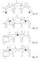
- Fig. 1 is a schematic representation of a chain sensor according to the invention 1 with a first reluctance sensor 2 to see in a perspective view.
- the reluctance sensor 2 has a yoke body 3 of a magnetically conductive or magnetic-field-permeable material, which in addition to a center leg 4 also has two yoke legs 5 extending laterally to the center leg 4.
- a coil 6 is arranged, which can extend over the entire length of the center leg 4 between the inner teeth 7 of the adjacent yoke leg 5.
- the yoke legs 5 have in addition to the adjacent to the center leg 4 inner teeth 7 and external teeth 8; which are each arranged at the outer end of the yoke legs.
- the inner teeth 7 and the outer teeth 8 project towards a middle section of the yoke legs 5 in the direction of a link chain 10, so that a cavity is formed between the inner teeth 7 and outer teeth 8 of the yoke legs 5 and the articulated chain 10, which in contrast to the magnetically conductive Yoke body 3 has a high magnetic resistance or a high reluctance with respect to the field lines of magnetic circuits.
- Permanent magnets 9 are provided on the external teeth 8 of the two yoke legs 5, respectively.
- the permanent magnets 9 are arranged at the tips of the external teeth 8 in the same polar direction, i. the free outer tips of the outer teeth 8 both have the positive pole or alternatively the negative pole of the permanent magnet 9.
- the inner teeth 7 and outer teeth 8 of the yoke legs 5 are aligned in the direction of the link chain 10, wherein the reluctance sensor 2, or the field lines of the magnetic circuits 13, 14 of the permanent magnet 9 as well as the side surfaces of the yoke body 3 substantially perpendicular to the hinge axes of the chain links 11 of the joint chain 10 stand.
- the tips of the inner teeth 7 and outer teeth 8 of the yoke legs 5 each only a small distance from the outer peripheral surface of the chain links 11, so that the link chain 10 can be moved substantially contactlessly on the reluctance sensor 2 along.
- the permanent magnets 9 at the tips of the outer teeth 8 of the yoke legs 5 form two magnetic circuits 13, 14, whose field lines run according to the Hopkinson law along the lowest magnetic resistance or the lowest reluctance.
- the coil 6 alternately from one of the two closed magnetic circuits 13, 14 are flooded, so that the coil 6 generates a characteristic voltage signal.
- a further magnetically conductive body are arranged, preferably a body with complementary to the internal teeth 7 and external teeth 8 of the yoke body 3 of the first reluctance sensor 2 arranged projections, or a second reluctance sensor 2 'with or without a second coil 6' to those of the Permanent magnets 9 induce magnetic circuits 13, 14 to close via the chain joints 11 of the articulated chain 10 with low reluctance.
- the designed as reluctance sensor 2 chain sensor 1 in Fig. 1 a has at each of the tips of the outer teeth 8 of the yoke legs 5, two permanent magnets 9, wherein the polar direction is the same in each case.
- the permanent magnets 9 may be positioned at a distance from the tips of the outer teeth 8 to better protect the permanent magnets 9 against wear and damage during operation.
- the inductive coil 6 is arranged between the lateral yoke legs 5 on the center leg 4 of the yoke body 3 and is alternately flooded by one, depending on the position of the link chain 10, closed over the yoke body 3 magnetic circuits 13, 14, so that the coil 6 a generates characteristic voltage signal.
- 1b shows an alternative embodiment of the reluctance sensor with an inductive coil 6 arranged on the center leg 4, in which the permanent magnets 9 are arranged in the region of the lateral yoke legs 5 of the magnetically conductive yoke body 3.
- the polar directions are aligned in the same direction in the direction of the outer teeth 8 and the inductive coil 6.
- a structurally different embodiment of the reluctance sensor 2 is in the Fig. 1c and 1d shown.
- the inductive coil 6 is disposed on one of the outer teeth 8 of the yoke legs 5.
- a prefabricated coil can be positioned on the outer teeth 8 and / or inner teeth 7, whereby the relatively complicated winding of a coil around the center leg 4 of the yoke body 3 can be avoided.
- the inductive coil 6 both on a the outer teeth 8 and the inner teeth 7 of the yoke body 3 are positioned.
- several or all inner teeth 7 and outer teeth 8 may be provided with an inductive coil 6.
- the arrangement of one or more inductive coils on the inner teeth 7 and outer teeth 8 of the yoke body 3 also requires the arrangement of the at least one permanent magnet 9 on the yoke legs 5 and 4 center leg of the yoke body 3 or one or more of the free inner teeth 7 or outer teeth.
- a permanent magnet 9 it is sufficient in this embodiment of a permanent magnet 9 use and, for example, to arrange on the center leg 4.
- two permanent magnets 9 on the yoke legs 5 of the yoke body 3 and the inner teeth 7 or outer teeth 8 of the yoke legs 5 may be arranged.
- the use of two permanent magnets on the yoke legs 5 not only strengthens the magnetic field lines of the magnetic circuits 13, 14, but also enables the formation of two closed magnetic circuits 13, 14 of similar field strength.
- Fig. 2a shows a preferred embodiment of a reluctance chain sensor 1 according to the invention with two reluctance sensors 2, 2 ', which are arranged at the top and bottom of the link chain 10 perpendicular to the hinge axes of the chain links 11.
- both reluctance sensors 2, 2 ' are provided with an inductive coil 6, 6', which is arranged in each case on the center leg 4 of the yoke body 3.
- the link chain 10 can move substantially contact-free or at least with low frictional resistance, between the two reluctance sensors 2, 2 ', wherein the distance between the associated outer teeth 8 and inner teeth 7 of the two reluctance sensors 2, 2' is only slightly larger than that Outer diameter of the chain links 11, so that the reluctance between the individual pairings of the outer teeth 8 and inner teeth 7 during the passage of a chain link 11 between the respective tooth pairings is minimized.
- the reluctance sensors 2, 2 'of the chain sensor 1 in Fig. 2a each have at the tips of the outer teeth 8, two permanent magnets 9, wherein the polar direction of the aligned on the link chain 10 permanent magnet 9 on the individual reluctance sensors 2, 2 'is equal to the permanent magnet 9 on the other reluctance sensors 2, 2', however is different.
- the polar directions of the associated permanent magnets 9 on the outer teeth 8 are different in each case, so that in each case a magnetic circuit 13, 14 is formed via the two associated permanent magnets 9. Consequently, the magnetic circuits 13, 14 each extend over both reluctance sensors 2, 2 '.
- the permanent magnets 9 at the tips of the outer teeth 8 of the right yoke legs 5 "produce despite the magnetic resistance through the chain gap between the Permanent magnet 9 on the outer teeth 8 another magnetic field, the second permanent magnetic circuit 14, which is closed over the chain joint 11 between the inner teeth 7 of the right yoke legs 5 "as a magnetic short circuit 14 'and thus essentially only on the right yoke legs 5" of two reluctance sensors 2, 2 'extends.
- Fig. 2b shows the already in Fig. 2a shown chain sensor 1 with two reluctance sensors 2, 2 ', which are arranged perpendicular to the hinge axis of the chain links 11 above and below the link chain 10.
- the link chain 10 by half a pitch of the chain links 11 further moved in the direction of the chain running direction.
- the magnetic circuit 14 is now closed on the inner teeth 7 of the left-side yoke leg 5 ', wherein the magnetic circuit 14 starting from the permanent magnet 9 at the tips of the right-side outer teeth 8, between which in this position Link chain 10 is a chain link 11 and reduces the magnetic resistance to the field lines of the magnetic circuit 14 to a minimum, on the right yoke legs 5 ", the middle leg 4 and the inner teeth 7 of the left-side yoke leg 5 'of the upper and lower reluctance sensor 2, 2nd 'as well as the chain joint 11 of the link chain 10 positioned between the inner teeth 7 of the left-side yoke legs 5', the magnetic circuit 14 induced by the permanent magnets 9 flows through the inductive coils 6, 6 'on the middle limbs 4 of the reluctance sensors 2, 2' in one Opposite direction to the in Fig.
- the in the Fig. 2a and 2 B Chain sensor 1 shown operates in the same way with a single reluctance sensor 2, the magnetic circuits 13,14 each close to the articulated chain 10.
- the other embodiments of the reluctance sensor 2 from the Fig. 1b to 1d used.
- the outer teeth 8 and inner teeth 7 of the yoke body 3 Through the outer teeth 8 and inner teeth 7 of the yoke body 3, two magnetic circuits 13, 14 with very different magnetic flux corresponding to the different reluctance along these magnetic circuits 13, 14 are obtained.
- the inductive coils 6, 6' alternately flooded by the magnetic circuits 13, 14, so that generates an AC voltage to the coils 6, 6 ' becomes.
- the coils 6, 6 'of the reluctance sensors 2, 2' can be connected in series or in parallel as required by the alternating signal.
- the alternating voltage applied to the inductive coils 6, 6 'of the reluctance sensors 2, 2' then reaches its maximum, when in each case between the inner teeth 7 and outer teeth 8 of the respective magnetic circuits 13, 14 chain joints 11 of the link chain 10 are positioned and so the magnetic resistance or the reluctance of the magnetic circuits 13, 14 is the lowest. Since the alternating voltage signal applied to the inductive coils 6, 6 'changes during operation of the articulated chain 10 due to the chain chain caused by wear, a more accurate time assignment of the signal to the position of the articulated chain 10 can be made possible by differentiating the alternating signal.
- comparators 15 For differentiating the alternating signal, it is possible, for example, to use comparators 15 with which both a noise superimposing the alternating voltage can be filtered out or only a small edge steepness of the alternating voltage can be compensated. Further, comparators 15 can prevent the signal voltage from switching too frequently and irregularly. By means of such comparators 15 is obtained From the originally induced AC voltage a clear square wave signal for evaluation of Kettenverschl formulatelfitung. In this case, the period of the rectangular signal is inversely proportional to the speed of the articulated chain 10.
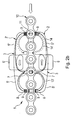
- a device for measuring the chain elongation of a joint chain 10 with two chain sensors 1, which are arranged at a distance from one another and through which the articulated chain 10 is guided in the operating state, is in Fig. 3 to see.
- a plurality of display units are further provided, a power indicator 16, a multi-stage wear indicator 17 and an emergency indicator 18, which may be configured in a simple embodiment as a colored light-emitting diodes.
- the entire device for measuring the chain elongation of the articulated chain 10 may be designed as a compact unit, which can be installed easily on existing systems with drive chains.
- the representation of the device according to the invention in Fig. 3 also shows the magnetic circuits 13, 14 over the two chain sensors 1.
- the position of the link chain 10 to that on the left side of the device in Fig. 3 provided chain sensor 1 allows a conclusion of the permanent magnetic circuit 13 via the coils 6, 6 'and a short circuit of the magnetic circuit 14' on the right yoke legs 5 "arranged on different sides of the link chain 10 Reluktanzsensoren 2, 2 ' is in detail already with respect to the Fig. 2A described.
- the link chain 10 is arranged so that between the pairs of teeth of the inner teeth 7 and outer teeth 8 is provided in each case a chain gap.
- Fig. 3 shown apparatus for measuring the chain elongation of a chain 10 with at least 2 chain sensors 1, each comprising at least one reluctance sensor 2, can be configured in addition with temperature sensors, such as an infrared temperature sensor for measuring the temperature of the articulated chain 10 and an additional Temperature sensor for measuring the temperature of the measuring device.
- temperature sensors such as an infrared temperature sensor for measuring the temperature of the articulated chain 10 and an additional Temperature sensor for measuring the temperature of the measuring device.
- the temperature-induced change in length of the articulated chain 10 can be taken into account in a calculation of the chain elongation and the change of the chain elongation can be determined more accurately and reliably.
- the measuring device can off Fig. 3 additionally be configured with an acceleration sensor or an alternative shock sensor.
- Fig. 4 shows the integration of the measuring device Fig. 3 in a signal and power supply circuit.
- an alternating voltage is generated by means of the movement of the articulated chain 10 by the two chain sensors 1 on the coils 6, 6 'of the individual reluctance sensors 2, 2', their magnitude and sign changed with the change of the permanent magnetic circuits 13, 14 through the coils 6, 6 '.
- the voltage generated by the coils 6, 6 ' which can be connected in series or in parallel according to the requirements of the measuring device, is fed to the signal and power supply circuit 19 and from there directly to the power supply 20, the signal and power supply circuit 19 takes into account the phase shift of the alternating voltages generated by the two chain sensors 1 of the device, as well as transmitted as a measurement signal via corresponding comparators 15 to the controller 21. In this case, a differentiation of the alternating voltage signal into a rectangular signal, which is used in the control 21 for determining the chain elongation of the articulated chain 10, takes place at the comparators 15.
- the energy required for operating the measuring device can be generated by the measuring device itself or the chain sensors 1 themselves via the alternating voltage transmitted by the two chain sensors 1 to the power supply 20. Accordingly, the inventive device for measuring the chain elongation can also be used generically and retrofitted to existing systems, without having to perform complex changes to the existing systems.
Landscapes
- Physics & Mathematics (AREA)
- General Physics & Mathematics (AREA)
- Measurement Of Length, Angles, Or The Like Using Electric Or Magnetic Means (AREA)
- Transmission And Conversion Of Sensor Element Output (AREA)
Priority Applications (4)
| Application Number | Priority Date | Filing Date | Title |
|---|---|---|---|
| EP15000167.5A EP2910904B1 (fr) | 2014-02-13 | 2015-01-21 | Capteur à chaîne à réluctance et procédé de mesure d'étirement de chaîne |
| JP2015025082A JP6547165B2 (ja) | 2014-02-13 | 2015-02-12 | チェーン伸長を測定するためのリラクタンス式チェーンセンサ及び測定方法 |
| US14/621,186 US9671251B2 (en) | 2014-02-13 | 2015-02-12 | Reluctance chain sensor and method of measuring the chain elongation |
| CN201510077521.1A CN104843455B (zh) | 2014-02-13 | 2015-02-13 | 磁阻链条传感器和测量链条伸长的方法 |
Applications Claiming Priority (2)
| Application Number | Priority Date | Filing Date | Title |
|---|---|---|---|
| EP14000520.8A EP2908097B1 (fr) | 2014-02-13 | 2014-02-13 | Capteur à réluctance pour chaîne et procédé de mesure d'étirement de chaîne |
| EP15000167.5A EP2910904B1 (fr) | 2014-02-13 | 2015-01-21 | Capteur à chaîne à réluctance et procédé de mesure d'étirement de chaîne |
Publications (2)
| Publication Number | Publication Date |
|---|---|
| EP2910904A1 true EP2910904A1 (fr) | 2015-08-26 |
| EP2910904B1 EP2910904B1 (fr) | 2016-06-29 |
Family
ID=50114262
Family Applications (2)
| Application Number | Title | Priority Date | Filing Date |
|---|---|---|---|
| EP14000520.8A Active EP2908097B1 (fr) | 2014-02-13 | 2014-02-13 | Capteur à réluctance pour chaîne et procédé de mesure d'étirement de chaîne |
| EP15000167.5A Active EP2910904B1 (fr) | 2014-02-13 | 2015-01-21 | Capteur à chaîne à réluctance et procédé de mesure d'étirement de chaîne |
Family Applications Before (1)
| Application Number | Title | Priority Date | Filing Date |
|---|---|---|---|
| EP14000520.8A Active EP2908097B1 (fr) | 2014-02-13 | 2014-02-13 | Capteur à réluctance pour chaîne et procédé de mesure d'étirement de chaîne |
Country Status (5)
| Country | Link |
|---|---|
| US (1) | US9671251B2 (fr) |
| EP (2) | EP2908097B1 (fr) |
| JP (1) | JP6547165B2 (fr) |
| CN (1) | CN104843455B (fr) |
| ES (2) | ES2609231T3 (fr) |
Cited By (1)
| Publication number | Priority date | Publication date | Assignee | Title |
|---|---|---|---|---|
| US20190086239A1 (en) * | 2017-09-19 | 2019-03-21 | Iwis Antriebssysteme Gmbh & Co. Kg | Device and method for determining the wear state of a chain |
Families Citing this family (13)
| Publication number | Priority date | Publication date | Assignee | Title |
|---|---|---|---|---|
| FI128485B (en) * | 2015-07-06 | 2020-06-15 | Konecranes Oyj | Arrangement and method for checking the condition of the chain |
| IT201600081324A1 (it) * | 2016-08-02 | 2018-02-02 | Campagnolo Srl | Dispositivo di comando per bicicletta |
| IT201600131314A1 (it) * | 2016-12-27 | 2018-06-27 | Campagnolo Srl | Deragliatore elettronico wireless di bicicletta |
| IT201600131281A1 (it) | 2016-12-27 | 2018-06-27 | Campagnolo Srl | Rilevatore per bicicletta |
| US20190170243A1 (en) * | 2017-12-05 | 2019-06-06 | GM Global Technology Operations LLC | Passive lubricant management system |
| EP3569558B1 (fr) * | 2018-05-16 | 2022-07-13 | Otis Elevator Company | Surveillance de défauts dans une chaîne de dispositif de transport de personnes |
| CN109058404B (zh) * | 2018-10-26 | 2024-01-02 | 伊维氏传动系统(平湖)有限公司 | 一种集成式液压双活塞张紧器 |
| DE102018129861B4 (de) | 2018-11-27 | 2022-10-06 | Sick Ag | Verfahren und Anordnung zur Bestimmung einer Kettenlänge einer Kette eines Antriebes |
| IT201900004253A1 (it) * | 2019-03-25 | 2020-09-25 | Sircatene S P A | Metodo e sistema di verifica della modifica di un organo di trasmissione quale una catena o una cinghia |
| DE102020202924A1 (de) | 2020-03-06 | 2021-09-09 | Gebhardt Fördertechnik GmbH | Antriebsvorrichtung für einen Förderwagen eines Verteilförderers |
| US11976999B2 (en) | 2020-07-02 | 2024-05-07 | U.S. Tsubaki Holdings, Inc. | Chain monitoring systems and methods |
| DE102021107899A1 (de) * | 2021-03-29 | 2022-09-29 | Iwis Antriebssysteme Gmbh & Co. Kg | Kettensensorvorichtung und verfahren zur ermittlung des verschleisses |
| CN113432544A (zh) * | 2021-06-29 | 2021-09-24 | 上海市特种设备监督检验技术研究院 | 一种链条快速检测装置和方法 |
Citations (6)
| Publication number | Priority date | Publication date | Assignee | Title |
|---|---|---|---|---|
| DE2709233A1 (de) * | 1977-03-03 | 1978-09-07 | Ruhrkohle Ag | Einrichtung zur hobelkettenueberwachung |
| US5291131A (en) | 1992-03-31 | 1994-03-01 | Tsubakimoto Chain Co. | Apparatus for measuring elongation of a circulating chain |
| DE4339595C1 (de) * | 1993-11-18 | 1995-01-12 | Robert Thalhammer | Vorrichtung zur Längenmessung an einer Gliederkette |
| EP1464919A1 (fr) | 2003-04-05 | 2004-10-06 | Renold Plc | Procédé et dispositif servant à contrôler l'usure des maillons d'une chaine |
| US7540374B2 (en) | 2006-08-24 | 2009-06-02 | Frost Links, Inc. | Chain wear monitoring device |
| WO2013113764A1 (fr) * | 2012-01-31 | 2013-08-08 | Rexnord Marbett S.R.L. | Système de surveillance servant à mesurer la vitesse et l'allongement de chaînes transporteuses |
Family Cites Families (5)
| Publication number | Priority date | Publication date | Assignee | Title |
|---|---|---|---|---|
| US6199021B1 (en) * | 1997-10-15 | 2001-03-06 | Cc Kinetics, Inc. | Method and apparatus for measuring power output of one powering a chain driven vehicle |
| DE102006016503A1 (de) * | 2006-04-07 | 2007-10-18 | Siemens Ag | Gebervorrichtung für eine elektrische Maschine |
| JP2009210550A (ja) * | 2008-02-29 | 2009-09-17 | Ribekkusu:Kk | チェーン位置・速度検出器 |
| ITMI20120120U1 (it) * | 2012-03-23 | 2013-09-24 | Riv Rubinetterie Italiane Velatta S Pa | Valvola di intercettazione per cisterne, serbatoi e simili |
| DE102012012308B3 (de) * | 2012-06-20 | 2013-02-28 | Ssb Wind Systems Gmbh & Co. Kg | Drehwinkelgeber für eine rotierende Welle |
-
2014
- 2014-02-13 ES ES14000520.8T patent/ES2609231T3/es active Active
- 2014-02-13 EP EP14000520.8A patent/EP2908097B1/fr active Active
-
2015
- 2015-01-21 EP EP15000167.5A patent/EP2910904B1/fr active Active
- 2015-01-21 ES ES15000167.5T patent/ES2589890T3/es active Active
- 2015-02-12 US US14/621,186 patent/US9671251B2/en active Active
- 2015-02-12 JP JP2015025082A patent/JP6547165B2/ja active Active
- 2015-02-13 CN CN201510077521.1A patent/CN104843455B/zh active Active
Patent Citations (6)
| Publication number | Priority date | Publication date | Assignee | Title |
|---|---|---|---|---|
| DE2709233A1 (de) * | 1977-03-03 | 1978-09-07 | Ruhrkohle Ag | Einrichtung zur hobelkettenueberwachung |
| US5291131A (en) | 1992-03-31 | 1994-03-01 | Tsubakimoto Chain Co. | Apparatus for measuring elongation of a circulating chain |
| DE4339595C1 (de) * | 1993-11-18 | 1995-01-12 | Robert Thalhammer | Vorrichtung zur Längenmessung an einer Gliederkette |
| EP1464919A1 (fr) | 2003-04-05 | 2004-10-06 | Renold Plc | Procédé et dispositif servant à contrôler l'usure des maillons d'une chaine |
| US7540374B2 (en) | 2006-08-24 | 2009-06-02 | Frost Links, Inc. | Chain wear monitoring device |
| WO2013113764A1 (fr) * | 2012-01-31 | 2013-08-08 | Rexnord Marbett S.R.L. | Système de surveillance servant à mesurer la vitesse et l'allongement de chaînes transporteuses |
Cited By (3)
| Publication number | Priority date | Publication date | Assignee | Title |
|---|---|---|---|---|
| US20190086239A1 (en) * | 2017-09-19 | 2019-03-21 | Iwis Antriebssysteme Gmbh & Co. Kg | Device and method for determining the wear state of a chain |
| DE102017121706A1 (de) * | 2017-09-19 | 2019-03-21 | Iwis Antriebssysteme Gmbh & Co. Kg | Vorrichtung und Verfahren zur Ermittlung des Verschleißzustandes einer Kette |
| US10801862B2 (en) | 2017-09-19 | 2020-10-13 | Iwis Antriebssysteme Gmbh & Co. Kg | Device and method for determining the wear state of a chain |
Also Published As
| Publication number | Publication date |
|---|---|
| US20150226582A1 (en) | 2015-08-13 |
| CN104843455A (zh) | 2015-08-19 |
| US9671251B2 (en) | 2017-06-06 |
| EP2908097A1 (fr) | 2015-08-19 |
| CN104843455B (zh) | 2019-06-04 |
| EP2908097B1 (fr) | 2016-11-16 |
| ES2589890T3 (es) | 2016-11-16 |
| EP2910904B1 (fr) | 2016-06-29 |
| JP6547165B2 (ja) | 2019-07-24 |
| ES2609231T3 (es) | 2017-04-19 |
| JP2015152600A (ja) | 2015-08-24 |
Similar Documents
| Publication | Publication Date | Title |
|---|---|---|
| EP2910904B1 (fr) | Capteur à chaîne à réluctance et procédé de mesure d'étirement de chaîne | |
| EP2188197B1 (fr) | Installation d'extraction, en particulier pour la mine, et procédé de commande de l'installation d'extraction | |
| EP2774252B1 (fr) | Moteur linéaire à plusieurs ensembles capteurs et à structure de stator modulaire | |
| DE102015102236B4 (de) | Steuerungssystem für einen elektrischen Motor | |
| DE102011075994B3 (de) | Vorrichtung und Verfahren zur Messung der Längung einer Kette, die endlos in der Vorrichtung umläuft | |
| DE102010043057B4 (de) | Antriebsvorrichtung und Verfahren | |
| DE102017121706A1 (de) | Vorrichtung und Verfahren zur Ermittlung des Verschleißzustandes einer Kette | |
| EP3475196B1 (fr) | Dispositif de transport et procédé permettant de commander et de contrôler l'expansion d'un dispositif de transport | |
| EP3058240B1 (fr) | Système de détection d'accouplement | |
| DE102013219761B3 (de) | Anordnung und Verfahren zum Messen eines Drehmomentes an einem Maschinenelement sowie Wankstabilisator | |
| DE102010050382A1 (de) | Betätigungssystem für eine elektromagnetische Synchronisierungseinrichtung | |
| EP3963303A1 (fr) | Procédé de surveillance d'un entraînement par courroie | |
| DE102017119300A1 (de) | Vorrichtung und Verfahren zur Ermittlung des Verschleisszustandes einer Kette | |
| DE102014223234B3 (de) | Verfahren und Vorrichtung zur Diagnose elektrischer Weichen | |
| DE102017119301A1 (de) | Vorrichtung und Verfahren zur Ermittlung des Verschleisszustandes einer Kette | |
| EP3653428A1 (fr) | Procédé de surveillance sûre du fonctionnement d'un moteur linéaire à stator long | |
| DE4343198C2 (de) | Verfahren und Vorrichtung zur Erfassung der Position rotierender Wellen | |
| WO2018193115A1 (fr) | Tête de capteur, capteur combiné, dispositif de mesure de couple et procédé de mesure de couple et de vitesse de rotation | |
| EP2290666B1 (fr) | Module auxiliaire pour appareil de surveillance de durée de vie pour commutateurs électromagnétiques et procédé correspondant | |
| EP3142244B1 (fr) | Procede de detection d'une perte de pas dans un moteur pas a pas et commande electronique associee d'un moteur pas a pas | |
| DE102021107899A1 (de) | Kettensensorvorichtung und verfahren zur ermittlung des verschleisses | |
| DE102021107898A1 (de) | Kettenlängungsüberwachungsvorrichtung und verfahren zur ermittlung des verschleisses | |
| DE112011105736B4 (de) | Positionsdetektoreinrichtung | |
| WO2020002092A1 (fr) | Dispositif de surveillance d'usure et vis à billes | |
| DE102018119466A1 (de) | Vorrichtung und Verfahren zur Ermittlung des Verschleißzustandes einer Kette |
Legal Events
| Date | Code | Title | Description |
|---|---|---|---|
| PUAI | Public reference made under article 153(3) epc to a published international application that has entered the european phase |
Free format text: ORIGINAL CODE: 0009012 |
|
| AK | Designated contracting states |
Kind code of ref document: A1 Designated state(s): AL AT BE BG CH CY CZ DE DK EE ES FI FR GB GR HR HU IE IS IT LI LT LU LV MC MK MT NL NO PL PT RO RS SE SI SK SM TR |
|
| AX | Request for extension of the european patent |
Extension state: BA ME |
|
| 17P | Request for examination filed |
Effective date: 20151013 |
|
| RBV | Designated contracting states (corrected) |
Designated state(s): AL AT BE BG CH CY CZ DE DK EE ES FI FR GB GR HR HU IE IS IT LI LT LU LV MC MK MT NL NO PL PT RO RS SE SI SK SM TR |
|
| REG | Reference to a national code |
Ref country code: DE Ref legal event code: R079 Ref document number: 502015000064 Country of ref document: DE Free format text: PREVIOUS MAIN CLASS: G01D0005200000 Ipc: G01M0013000000 |
|
| GRAP | Despatch of communication of intention to grant a patent |
Free format text: ORIGINAL CODE: EPIDOSNIGR1 |
|
| RIC1 | Information provided on ipc code assigned before grant |
Ipc: G01M 13/00 20060101AFI20160217BHEP Ipc: G01D 5/20 20060101ALI20160217BHEP |
|
| INTG | Intention to grant announced |
Effective date: 20160315 |
|
| GRAS | Grant fee paid |
Free format text: ORIGINAL CODE: EPIDOSNIGR3 |
|
| GRAA | (expected) grant |
Free format text: ORIGINAL CODE: 0009210 |
|
| RIN1 | Information on inventor provided before grant (corrected) |
Inventor name: MADLENER, FLORIAN Inventor name: KREISFELD, PETER Inventor name: SIRAKY, JOSEF |
|
| AK | Designated contracting states |
Kind code of ref document: B1 Designated state(s): AL AT BE BG CH CY CZ DE DK EE ES FI FR GB GR HR HU IE IS IT LI LT LU LV MC MK MT NL NO PL PT RO RS SE SI SK SM TR |
|
| REG | Reference to a national code |
Ref country code: GB Ref legal event code: FG4D Free format text: NOT ENGLISH |
|
| REG | Reference to a national code |
Ref country code: CH Ref legal event code: EP |
|
| REG | Reference to a national code |
Ref country code: AT Ref legal event code: REF Ref document number: 809487 Country of ref document: AT Kind code of ref document: T Effective date: 20160715 Ref country code: CH Ref legal event code: NV Representative=s name: BOVARD AG, CH |
|
| REG | Reference to a national code |
Ref country code: IE Ref legal event code: FG4D Free format text: LANGUAGE OF EP DOCUMENT: GERMAN |
|
| REG | Reference to a national code |
Ref country code: DE Ref legal event code: R096 Ref document number: 502015000064 Country of ref document: DE |
|
| REG | Reference to a national code |
Ref country code: LT Ref legal event code: MG4D |
|
| PG25 | Lapsed in a contracting state [announced via postgrant information from national office to epo] |
Ref country code: NO Free format text: LAPSE BECAUSE OF FAILURE TO SUBMIT A TRANSLATION OF THE DESCRIPTION OR TO PAY THE FEE WITHIN THE PRESCRIBED TIME-LIMIT Effective date: 20160929 Ref country code: LT Free format text: LAPSE BECAUSE OF FAILURE TO SUBMIT A TRANSLATION OF THE DESCRIPTION OR TO PAY THE FEE WITHIN THE PRESCRIBED TIME-LIMIT Effective date: 20160629 Ref country code: FI Free format text: LAPSE BECAUSE OF FAILURE TO SUBMIT A TRANSLATION OF THE DESCRIPTION OR TO PAY THE FEE WITHIN THE PRESCRIBED TIME-LIMIT Effective date: 20160629 |
|
| REG | Reference to a national code |
Ref country code: NL Ref legal event code: MP Effective date: 20160629 |
|
| REG | Reference to a national code |
Ref country code: ES Ref legal event code: FG2A Ref document number: 2589890 Country of ref document: ES Kind code of ref document: T3 Effective date: 20161116 |
|
| PG25 | Lapsed in a contracting state [announced via postgrant information from national office to epo] |
Ref country code: NL Free format text: LAPSE BECAUSE OF FAILURE TO SUBMIT A TRANSLATION OF THE DESCRIPTION OR TO PAY THE FEE WITHIN THE PRESCRIBED TIME-LIMIT Effective date: 20160629 Ref country code: SE Free format text: LAPSE BECAUSE OF FAILURE TO SUBMIT A TRANSLATION OF THE DESCRIPTION OR TO PAY THE FEE WITHIN THE PRESCRIBED TIME-LIMIT Effective date: 20160629 Ref country code: GR Free format text: LAPSE BECAUSE OF FAILURE TO SUBMIT A TRANSLATION OF THE DESCRIPTION OR TO PAY THE FEE WITHIN THE PRESCRIBED TIME-LIMIT Effective date: 20160930 Ref country code: LV Free format text: LAPSE BECAUSE OF FAILURE TO SUBMIT A TRANSLATION OF THE DESCRIPTION OR TO PAY THE FEE WITHIN THE PRESCRIBED TIME-LIMIT Effective date: 20160629 Ref country code: RS Free format text: LAPSE BECAUSE OF FAILURE TO SUBMIT A TRANSLATION OF THE DESCRIPTION OR TO PAY THE FEE WITHIN THE PRESCRIBED TIME-LIMIT Effective date: 20160629 Ref country code: HR Free format text: LAPSE BECAUSE OF FAILURE TO SUBMIT A TRANSLATION OF THE DESCRIPTION OR TO PAY THE FEE WITHIN THE PRESCRIBED TIME-LIMIT Effective date: 20160629 |
|
| REG | Reference to a national code |
Ref country code: FR Ref legal event code: PLFP Year of fee payment: 3 |
|
| PG25 | Lapsed in a contracting state [announced via postgrant information from national office to epo] |
Ref country code: IS Free format text: LAPSE BECAUSE OF FAILURE TO SUBMIT A TRANSLATION OF THE DESCRIPTION OR TO PAY THE FEE WITHIN THE PRESCRIBED TIME-LIMIT Effective date: 20161029 Ref country code: RO Free format text: LAPSE BECAUSE OF FAILURE TO SUBMIT A TRANSLATION OF THE DESCRIPTION OR TO PAY THE FEE WITHIN THE PRESCRIBED TIME-LIMIT Effective date: 20160629 Ref country code: CZ Free format text: LAPSE BECAUSE OF FAILURE TO SUBMIT A TRANSLATION OF THE DESCRIPTION OR TO PAY THE FEE WITHIN THE PRESCRIBED TIME-LIMIT Effective date: 20160629 Ref country code: EE Free format text: LAPSE BECAUSE OF FAILURE TO SUBMIT A TRANSLATION OF THE DESCRIPTION OR TO PAY THE FEE WITHIN THE PRESCRIBED TIME-LIMIT Effective date: 20160629 Ref country code: SK Free format text: LAPSE BECAUSE OF FAILURE TO SUBMIT A TRANSLATION OF THE DESCRIPTION OR TO PAY THE FEE WITHIN THE PRESCRIBED TIME-LIMIT Effective date: 20160629 |
|
| PG25 | Lapsed in a contracting state [announced via postgrant information from national office to epo] |
Ref country code: PL Free format text: LAPSE BECAUSE OF FAILURE TO SUBMIT A TRANSLATION OF THE DESCRIPTION OR TO PAY THE FEE WITHIN THE PRESCRIBED TIME-LIMIT Effective date: 20160629 Ref country code: SM Free format text: LAPSE BECAUSE OF FAILURE TO SUBMIT A TRANSLATION OF THE DESCRIPTION OR TO PAY THE FEE WITHIN THE PRESCRIBED TIME-LIMIT Effective date: 20160629 Ref country code: PT Free format text: LAPSE BECAUSE OF FAILURE TO SUBMIT A TRANSLATION OF THE DESCRIPTION OR TO PAY THE FEE WITHIN THE PRESCRIBED TIME-LIMIT Effective date: 20161031 |
|
| REG | Reference to a national code |
Ref country code: DE Ref legal event code: R097 Ref document number: 502015000064 Country of ref document: DE |
|
| PG25 | Lapsed in a contracting state [announced via postgrant information from national office to epo] |
Ref country code: BE Free format text: LAPSE BECAUSE OF NON-PAYMENT OF DUE FEES Effective date: 20170131 Ref country code: DK Free format text: LAPSE BECAUSE OF FAILURE TO SUBMIT A TRANSLATION OF THE DESCRIPTION OR TO PAY THE FEE WITHIN THE PRESCRIBED TIME-LIMIT Effective date: 20160629 |
|
| 26N | No opposition filed |
Effective date: 20170330 |
|
| PLBE | No opposition filed within time limit |
Free format text: ORIGINAL CODE: 0009261 |
|
| STAA | Information on the status of an ep patent application or granted ep patent |
Free format text: STATUS: NO OPPOSITION FILED WITHIN TIME LIMIT |
|
| PG25 | Lapsed in a contracting state [announced via postgrant information from national office to epo] |
Ref country code: SI Free format text: LAPSE BECAUSE OF FAILURE TO SUBMIT A TRANSLATION OF THE DESCRIPTION OR TO PAY THE FEE WITHIN THE PRESCRIBED TIME-LIMIT Effective date: 20160629 Ref country code: BG Free format text: LAPSE BECAUSE OF FAILURE TO SUBMIT A TRANSLATION OF THE DESCRIPTION OR TO PAY THE FEE WITHIN THE PRESCRIBED TIME-LIMIT Effective date: 20160929 |
|
| PG25 | Lapsed in a contracting state [announced via postgrant information from national office to epo] |
Ref country code: MC Free format text: LAPSE BECAUSE OF FAILURE TO SUBMIT A TRANSLATION OF THE DESCRIPTION OR TO PAY THE FEE WITHIN THE PRESCRIBED TIME-LIMIT Effective date: 20160629 |
|
| REG | Reference to a national code |
Ref country code: IE Ref legal event code: MM4A |
|
| PG25 | Lapsed in a contracting state [announced via postgrant information from national office to epo] |
Ref country code: LU Free format text: LAPSE BECAUSE OF NON-PAYMENT OF DUE FEES Effective date: 20170121 |
|
| REG | Reference to a national code |
Ref country code: FR Ref legal event code: PLFP Year of fee payment: 4 |
|
| REG | Reference to a national code |
Ref country code: BE Ref legal event code: MM Effective date: 20170131 |
|
| PG25 | Lapsed in a contracting state [announced via postgrant information from national office to epo] |
Ref country code: IE Free format text: LAPSE BECAUSE OF NON-PAYMENT OF DUE FEES Effective date: 20170121 |
|
| PG25 | Lapsed in a contracting state [announced via postgrant information from national office to epo] |
Ref country code: MT Free format text: LAPSE BECAUSE OF FAILURE TO SUBMIT A TRANSLATION OF THE DESCRIPTION OR TO PAY THE FEE WITHIN THE PRESCRIBED TIME-LIMIT Effective date: 20160629 |
|
| PG25 | Lapsed in a contracting state [announced via postgrant information from national office to epo] |
Ref country code: AL Free format text: LAPSE BECAUSE OF FAILURE TO SUBMIT A TRANSLATION OF THE DESCRIPTION OR TO PAY THE FEE WITHIN THE PRESCRIBED TIME-LIMIT Effective date: 20160629 |
|
| PG25 | Lapsed in a contracting state [announced via postgrant information from national office to epo] |
Ref country code: HU Free format text: LAPSE BECAUSE OF FAILURE TO SUBMIT A TRANSLATION OF THE DESCRIPTION OR TO PAY THE FEE WITHIN THE PRESCRIBED TIME-LIMIT; INVALID AB INITIO Effective date: 20150121 |
|
| PG25 | Lapsed in a contracting state [announced via postgrant information from national office to epo] |
Ref country code: CY Free format text: LAPSE BECAUSE OF FAILURE TO SUBMIT A TRANSLATION OF THE DESCRIPTION OR TO PAY THE FEE WITHIN THE PRESCRIBED TIME-LIMIT Effective date: 20160629 |
|
| PG25 | Lapsed in a contracting state [announced via postgrant information from national office to epo] |
Ref country code: MK Free format text: LAPSE BECAUSE OF FAILURE TO SUBMIT A TRANSLATION OF THE DESCRIPTION OR TO PAY THE FEE WITHIN THE PRESCRIBED TIME-LIMIT Effective date: 20160629 |
|
| PG25 | Lapsed in a contracting state [announced via postgrant information from national office to epo] |
Ref country code: TR Free format text: LAPSE BECAUSE OF FAILURE TO SUBMIT A TRANSLATION OF THE DESCRIPTION OR TO PAY THE FEE WITHIN THE PRESCRIBED TIME-LIMIT Effective date: 20160629 |
|
| PGFP | Annual fee paid to national office [announced via postgrant information from national office to epo] |
Ref country code: CH Payment date: 20220125 Year of fee payment: 8 Ref country code: AT Payment date: 20220119 Year of fee payment: 8 |
|
| PGFP | Annual fee paid to national office [announced via postgrant information from national office to epo] |
Ref country code: ES Payment date: 20220216 Year of fee payment: 8 |
|
| P01 | Opt-out of the competence of the unified patent court (upc) registered |
Effective date: 20230724 |
|
| REG | Reference to a national code |
Ref country code: CH Ref legal event code: PL |
|
| REG | Reference to a national code |
Ref country code: AT Ref legal event code: MM01 Ref document number: 809487 Country of ref document: AT Kind code of ref document: T Effective date: 20230121 |
|
| PG25 | Lapsed in a contracting state [announced via postgrant information from national office to epo] |
Ref country code: LI Free format text: LAPSE BECAUSE OF NON-PAYMENT OF DUE FEES Effective date: 20230131 Ref country code: CH Free format text: LAPSE BECAUSE OF NON-PAYMENT OF DUE FEES Effective date: 20230131 Ref country code: AT Free format text: LAPSE BECAUSE OF NON-PAYMENT OF DUE FEES Effective date: 20230121 |
|
| REG | Reference to a national code |
Ref country code: ES Ref legal event code: FD2A Effective date: 20240402 |
|
| PG25 | Lapsed in a contracting state [announced via postgrant information from national office to epo] |
Ref country code: ES Free format text: LAPSE BECAUSE OF NON-PAYMENT OF DUE FEES Effective date: 20230122 |
|
| PG25 | Lapsed in a contracting state [announced via postgrant information from national office to epo] |
Ref country code: ES Free format text: LAPSE BECAUSE OF NON-PAYMENT OF DUE FEES Effective date: 20230122 |
|
| PGFP | Annual fee paid to national office [announced via postgrant information from national office to epo] |
Ref country code: GB Payment date: 20260122 Year of fee payment: 12 |
|
| PGFP | Annual fee paid to national office [announced via postgrant information from national office to epo] |
Ref country code: DE Payment date: 20260120 Year of fee payment: 12 |
|
| PGFP | Annual fee paid to national office [announced via postgrant information from national office to epo] |
Ref country code: IT Payment date: 20260130 Year of fee payment: 12 |
|
| PGFP | Annual fee paid to national office [announced via postgrant information from national office to epo] |
Ref country code: FR Payment date: 20260121 Year of fee payment: 12 |