EP3475196B1 - Dispositif de transport et procédé permettant de commander et de contrôler l'expansion d'un dispositif de transport - Google Patents
Dispositif de transport et procédé permettant de commander et de contrôler l'expansion d'un dispositif de transport Download PDFInfo
- Publication number
- EP3475196B1 EP3475196B1 EP17727169.9A EP17727169A EP3475196B1 EP 3475196 B1 EP3475196 B1 EP 3475196B1 EP 17727169 A EP17727169 A EP 17727169A EP 3475196 B1 EP3475196 B1 EP 3475196B1
- Authority
- EP
- European Patent Office
- Prior art keywords
- transport element
- sensor
- rotational angle
- drive unit
- control unit
- Prior art date
- Legal status (The legal status is an assumption and is not a legal conclusion. Google has not performed a legal analysis and makes no representation as to the accuracy of the status listed.)
- Active
Links
Images
Classifications
-
- B—PERFORMING OPERATIONS; TRANSPORTING
- B65—CONVEYING; PACKING; STORING; HANDLING THIN OR FILAMENTARY MATERIAL
- B65G—TRANSPORT OR STORAGE DEVICES, e.g. CONVEYORS FOR LOADING OR TIPPING, SHOP CONVEYOR SYSTEMS OR PNEUMATIC TUBE CONVEYORS
- B65G43/00—Control devices, e.g. for safety, warning or fault-correcting
- B65G43/10—Sequence control of conveyors operating in combination
-
- B—PERFORMING OPERATIONS; TRANSPORTING
- B65—CONVEYING; PACKING; STORING; HANDLING THIN OR FILAMENTARY MATERIAL
- B65G—TRANSPORT OR STORAGE DEVICES, e.g. CONVEYORS FOR LOADING OR TIPPING, SHOP CONVEYOR SYSTEMS OR PNEUMATIC TUBE CONVEYORS
- B65G23/00—Driving gear for endless conveyors; Belt- or chain-tensioning arrangements
- B65G23/44—Belt or chain tensioning arrangements
-
- B—PERFORMING OPERATIONS; TRANSPORTING
- B65—CONVEYING; PACKING; STORING; HANDLING THIN OR FILAMENTARY MATERIAL
- B65G—TRANSPORT OR STORAGE DEVICES, e.g. CONVEYORS FOR LOADING OR TIPPING, SHOP CONVEYOR SYSTEMS OR PNEUMATIC TUBE CONVEYORS
- B65G43/00—Control devices, e.g. for safety, warning or fault-correcting
-
- B—PERFORMING OPERATIONS; TRANSPORTING
- B65—CONVEYING; PACKING; STORING; HANDLING THIN OR FILAMENTARY MATERIAL
- B65G—TRANSPORT OR STORAGE DEVICES, e.g. CONVEYORS FOR LOADING OR TIPPING, SHOP CONVEYOR SYSTEMS OR PNEUMATIC TUBE CONVEYORS
- B65G43/00—Control devices, e.g. for safety, warning or fault-correcting
- B65G43/02—Control devices, e.g. for safety, warning or fault-correcting detecting dangerous physical condition of load carriers, e.g. for interrupting the drive in the event of overheating
-
- B—PERFORMING OPERATIONS; TRANSPORTING
- B65—CONVEYING; PACKING; STORING; HANDLING THIN OR FILAMENTARY MATERIAL
- B65G—TRANSPORT OR STORAGE DEVICES, e.g. CONVEYORS FOR LOADING OR TIPPING, SHOP CONVEYOR SYSTEMS OR PNEUMATIC TUBE CONVEYORS
- B65G43/00—Control devices, e.g. for safety, warning or fault-correcting
- B65G43/04—Control devices, e.g. for safety, warning or fault-correcting detecting slip between driving element and load-carrier, e.g. for interrupting the drive
Definitions
- the invention relates to a device for transporting containers or bundles, comprising an endlessly revolving transport element, a drive unit for driving the revolving transport element, a control unit for controlling the drive unit and at least one stationary sensor for detecting at least one position mark of the transport element. Furthermore, the invention relates to a method for controlling and monitoring a transport device.
- Devices for transporting containers or bundles and methods for controlling and monitoring such a transport device are known in a variety of configurations from the prior art. Corresponding devices and methods are used in the production and packaging of goods, in particular food. However, corresponding transport devices are also used in numerous other areas, in particular in the production, processing or storage of goods and goods.
- a well-known problem of such transport devices is that the endlessly circulating transport elements, mostly belts or chains, are subject to a change in length over the period of use.
- these changes in length occur uniformly over the entire transport element due to forces acting during the period of use, depending on the material of the transport device.
- length changes also occur depending on the location on the transport element due to different properties, for example a different material thickness, hardening of a metal or crosslinking of a polymer.
- Other external influences such as dirt, temperature changes, humidity or the respective lubrication also contribute to changes in length.
- a change in length of the transport element results in the speed of the transport element changing as a function of the change in length during constant operation of the drive unit. Because of this, an asynchronicity can occur between the transport device and other devices that interact with it or other parallel or subsequent transport devices. Particularly in a transfer area from one transport device to another transport device, it is of crucial importance that the adjoining transport devices have synchronous speeds in order to avoid undesired forces on the transported containers or packs due to relative speeds occurring in the transfer area. Even with several transport devices arranged parallel to one another, a speed difference leads to an undesired twisting of the transported containers or packs in relation to the transport direction.
- At least two sensors are arranged along the endlessly revolving transport element, which monitor at least one identifier on the transport element.
- a method and a device for monitoring the wear of chain links in which a circulating chain has two identifiers that can be detected by two sensors.
- the first sensor is fixed to the device, while the second sensor can be moved along the chain.
- the second sensor is positioned along the chain in such a way that both sensors each detect an identifier at the same time.
- the chain is stretched, there is a time delay in the triggering of the two sensors, where synchronicity of the signals is moved and the distance required for this is recorded by the second sensor.
- DE 10 2010 043057 A1 discloses the preamble of claim 9.
- U.S. 2008 082206 A1 discloses the preamble of claim 1.
- the EP 1 850 087 A1 further discloses a system with a revolving drive chain engaged with a rotating sprocket, which also includes an arrangement for monitoring the chain elongation, with two stationary sensors and an evaluation unit.
- the sensors are designed such that by means of the first sensor, the passage movement of the chain elements on the first Sensor and by means of the second sensor, the rotational movement of the gear is detected.
- the evaluation unit compares these two values.
- the object is now to provide a device for the production of containers or bundles and a corresponding method that enables reliable monitoring of the expansion of a transport element and precise control of the speed of the transport element in a particularly simple manner and with particularly few components, and at the same time particularly inexpensively to be manufactured and operated.
- the device according to the invention for transporting containers or bundles has an endlessly revolving transport element, a drive unit for driving the revolving transport element, a control unit for controlling the drive unit and at least one stationary sensor for detecting at least one position mark of the transport element.
- the drive unit comprises a means for position or setting output, in particular a rotation angle sensor.
- the control unit is connected to the means for position or tion with increasing temperatures during operation or due to mechanical influences and thus the accuracy of the measurements decreases.
- the device according to the invention for transporting containers or bundles has an endlessly revolving transport element, a drive unit for driving the revolving transport element, a control unit for controlling the drive unit and at least one stationary sensor for detecting at least one position mark of the transport element.
- the drive unit comprises a means for position or setting output, in particular a rotation angle sensor.
- the control unit is connected to the means for position or setting output and to the sensor in such a way that the drive unit can be controlled and/or an elongation of the transport element can be calculated using the data from the means for position or setting output and the sensor.
- the inventors of the device according to the invention have recognized that two sensors arranged on a transport element with a position mark are not necessary in order to reliably detect the actual speed and/or the elongation of the transport element, but that one sensor and one in the drive unit can also be used arranged rotary encoder in an even simpler way monitoring and / or control of the device is possible.
- the omission of a second sensor along the transport element leads to an advantageous simplification of the structure and to savings in manufacturing costs.
- the determination also Control output and connected to the sensor that the drive unit can be controlled by means of the data of the means for position or control output and the sensor and / or an elongation of the transport element can be calculated.
- the inventors of the device according to the invention have recognized that two sensors arranged on a transport element with a position mark are not necessary in order to reliably detect the actual speed and/or the elongation of the transport element, but that one sensor and one in the drive unit can also be used arranged rotary encoder in an even simpler way monitoring and / or control of the device is possible.
- the omission of a second sensor along the transport element leads to an advantageous simplification of the structure and to a more accurate and reliable, as the rotary encoder is usually installed inside the drive unit and is therefore less susceptible to interference.
- a first angle of rotation is first detected by means of the rotary encoder when the position mark is detected by the sensor detected and stored in a control unit as a reference angle of rotation. At least one further angle of rotation is then determined when the position mark is detected again by the sensor and transmitted to the control unit. The detected angle of rotation is then compared with the reference angle of rotation in the control unit and the speed of the drive unit can be regulated and/or the elongation of the transport element can be determined using the result obtained during the comparison or from the change in the results obtained over time.
- the method according to the invention makes it possible in a particularly simple manner when tribological effects occur in the area of the transport element, in particular a change in length and in particular an elongation, to determine these since the position mark reaches the sensor later in relation to the measured angle of rotation with an elongated transport element. Furthermore, it is possible to adapt the speed of the transport element, in particular by accelerating the drive unit accordingly, or to keep it constant over the entire operating time. This is particularly important in order to ensure problem-free transfer of the transported containers or packs from or onto the transport element, for example when transferring from a transport starwheel or to another transport element. A speed that is not adjusted can not only result in undesired forces acting on the container or container, but also cause the container or container to twist, making subsequent work steps more difficult.
- the device according to the invention is suitable for transporting containers and/or bundles by means of a transport element.
- Containers are in particular bottles, cans or barrels made of metal, glass, plastic and/or a composite material.
- a container is initially understood to be any arrangement of at least two containers, preferably at least four and particularly preferably at least six containers, in which the containers are spatially fixed in a predetermined position in relation to one another.
- the containers can in principle be arranged directly on one another, for example by means of an adhesive bond, but can also be connected to one another via a further element.
- the transport element is initially any component or assembly that is suitable for transporting a number of containers or bundles, with the containers or bundles preferably standing or lying on the transport element at least in sections, preferably completely during transport.
- the transport element is particularly preferably a transport belt or a transport chain.
- the conveyor belt is preferably made of plastic, rubber and/or a fabric and particularly preferably has a fiber reinforcement or an embedded reinforcement fabric.
- the conveyor belt is formed in one piece.
- a transport chain is preferably formed from a plurality of chain links made of metal and/or plastic, with all chain links particularly preferably being constructed identically.
- the transport element is formed to be endlessly revolving, i.e. the transport element has no end in one spatial direction, in particular the direction of movement in the transport device, but is formed and arranged in the device in such a way that one point of the transport element changes after a complete revolution again in the same position.
- the transport element is deflected at least twice in the device, the deflection basically taking place by means of any deflection element, preferably by means of at least one drive roller of the drive unit and/or at least one deflection roller.
- the transport element is particularly preferably deflected at one end on the drive unit and at the other end by means of a deflection roller.
- the drive unit according to the invention can be any subassembly that is provided for driving the transport element.
- the drive unit can also include other components such as gears, axles, deflection or drive rollers, in particular for the transport element.
- the drive unit basically has a motor with a rotary encoder or a means for position or setting output.
- the motor is an electric motor or electromagnetic drive.
- the motor is particularly preferably a servomotor with an integrated rotary encoder.
- the motor is preferably infinitely variable.
- a rotary encoder is initially understood to mean any means for position or setting output of the drive unit, in particular an output shaft of the drive unit or a drive shaft of the transport element.
- the rotary encoder is basically a sensor that detects a rotary angle or a measure of the rotary angle.
- the rotary encoder is preferably an incremental encoder for detecting a change in angle, in particular in the sense of a digital endless potentiometer.
- the angle of rotation sensor can be measured in any way, for example by means of photoelectric scanning, a sliding contact, magnetic scanning or by means of a gear wheel sensor.
- the rotary encoder is particularly preferably integrated in a motor, in particular in the servomotor of the drive unit.
- the angle of rotation determined can be both an actual angle specification and also any value representing an angle.
- the angle of rotation or angle of rotation value can also only be determined by means of the control unit, for example if the rotary encoder is an incremental encoder and the respective angle value is only determined in the control unit using the known number of increments representing a full revolution. The same also applies to the reference angle of rotation.
- the control unit is basically a data processing system that is used to record or feed in signals from a number of sensors, at least but the sensor is suitable for the position mark of the transport element and the rotary encoder.
- the measured sensor data can be processed at least partially, preferably completely, and/or the drive unit can be controlled by means of the control unit.
- the control unit preferably has a user interface or an interface for connecting a device that includes a user interface.
- the control unit has at least one additional interface for coupling to at least one additional control unit.
- the control unit is particularly preferably digitally programmable, with the programming being able to take place both by means of a user interface of the control unit and by means of a further data processing system which can be connected to the control unit, in particular a computer or tablet.
- the user interface preferably includes both input means, for example keys, and output means, in particular a screen, a touch-sensitive screen being particularly preferably provided as input and output means at the same time.
- the control unit is very particularly preferably a programmable logic controller (PLC).
- PLC programmable logic controller
- the drive unit is also preferably controlled and/or the expansion of the transport element is calculated entirely by means of the control unit.
- control unit can be connected to the at least one sensor and to the rotary encoder in any desired manner.
- a wireless connection for example by means of radio or radio frequency, infrared, or in some other way by means of optical signals or radio signals, as well as by means of an electrical conductor or an optical fiber is possible.
- the connection is preferably made in each case by means of an electrical conductor.
- the sensor and/or the rotary encoder can be connected both directly to the control unit and to the control unit via other components, such as encoders, converters or the like.
- the sensor can be any sensor that is suitable for detecting the position mark of the transport element. In the simplest case, this can be a mechanical sensor, for example a switch, which is controlled by the position mark moving past directly or via others components is actuated. Furthermore, it can also be a non-contact sensor that detects the position mark in particular optically or electromagnetically. The detection can take place quantitatively or digitally, with it only being detected that the position mark was in the measuring range of the sensor. Alternatively, a qualitative or analog measurement can also be carried out, in which the strength of the signal or another characteristic is determined when the position mark is detected.
- the sensor is basically fixed stationary on the device, so that the sensor does not have to or cannot be moved during operation and/or during the method according to the invention.
- the sensor can also be movably attached to the device, for example pivotably, for example to facilitate cleaning of the transport element, but the position of use of the sensor must be stationary, i.e. constant and immobile.
- the sensor is preferably arranged on the device so that it can be aligned, so that the sensor can be used in an ideal position for detecting the position mark and fixed there in a stationary manner.
- the position marker is a component or alternatively a part of the transport element that is designed and differs from the rest of the transport element in such a way that it can be reliably detected by the sensor.
- the position marker is preferably located on a surface of the transport element that faces away from the opposite side of the endlessly revolving transport element and/or that is in an installed position of the device on the upper side of the transport element for receiving containers or bundles.
- the position mark is preferably arranged on the edge of the transport element in such a way that containers or bundles transported on the transport element cannot cover the position mark.
- the control of the drive unit or the drive element by means of the control unit is preferably a dynamic control, ie the data from the sensor and the rotary encoder are processed directly and the speed of the drive element is also controlled directly, in particular each time the position mark is detected by the sensor.
- the speed can also be adjusted only after a specified number of triggerings of the sensor, for example after every tenth or one hundredth sensor triggering.
- the storage of the reference angle of rotation can either be triggered manually, for example by means of a button or a user interface, or it can take place automatically, for example by means of a sensor for changing the transport element.
- the reference angle of rotation is preferably defined after a change and/or after a predefined arrival of a new transport element.
- an angle of rotation is determined in order to be able to compare it with the reference angle of rotation. This preferably takes place as part of a continuous determination of the angle of rotation each time the position mark is detected by the sensor, whereby not only the influence of wear on the transport element but also the influence of containers or bundles on the transport element can be taken into account.
- angles of rotation can also be determined discontinuously at predetermined, longer time intervals, for example hourly, daily or weekly.
- a preferred embodiment of the device according to the invention has precisely one sensor per transport element, as a result of which the device can be manufactured particularly cheaply.
- the device particularly preferably has precisely one sensor on the transport element.
- An embodiment of the device with exactly one position mark per transport element is also preferred, as a result of which the transport element, which has to be renewed regularly as a closing part, can be produced particularly simply and inexpensively.
- At least two identical sensors are arranged offset to one another along the transport element and interact with the control unit in such a way that the data from each sensor can be processed with data from the rotary encoder in order to determine the elongation of the transport element and /or to enable section-resolved dynamic speed control of the drive unit.
- the sensors are preferably offset from one another at the opposite ends or sides of the transport element.
- the distance between all adjacent sensors along the transport element is very particularly preferably the same. If several sensors are used, the values of the rotary encoder determined when the position mark is detected are also preferably compared with a reference rotary angle specific to the respective sensor.
- an embodiment of the device according to the invention is also conceivable, in which several position marks are arranged on the transport element, which are detected by a sensor, so that in this way a section-by-section determination of the elongation of the transport element by means of the change over time in the difference of the respective angle of rotation with a corresponding reference value and multiple control of the speed are possible with a full rotation of the transport element.
- the distance between the sensor and the drive unit corresponds to at least 50%, preferably at least 80%, particularly preferably at least 90% and very particularly preferably at least 95% of the length of the load strand of the transport element, which in particular the expansion and speed of the part of the transport element loaded with containers or bundles can be measured and correspondingly controlled in a simple manner.
- the sensor is very particularly preferably at the greatest possible distance from the drive unit, in particular from the rotary encoder of the drive unit, following the load strand.
- the load strand is the entire pulled part of the drive element and preferably corresponds to approximately half the length of the endlessly circulating transport element.
- the load side is particularly preferably the pulled part of the transport element between the single drive unit and the deflection roller that is furthest away from the drive unit.
- the at least one position mark is formed by one or more switch lugs attached to the transport element, as a result of which the transport element can be manufactured particularly cheaply independently of the position mark and, at the same time, in the event of a defect or wear of the transport element or the position mark, this or this is particularly easy and inexpensive to replace.
- the switching lug can be a component for mechanical as well as contactless triggering of the sensor or registration by the sensor.
- the switching lug is preferably formed in one piece.
- the switch flag is also preferably fixed to the transport element in a materially bonded and/or non-positive manner.
- switch lugs or position marks are essentially the same but slightly different, for example by using switch lugs of different lengths.
- a position such as a zero position, can be clearly determined and thus part of the transport device can also be recognized.
- the at least one position mark or switching flag is part of the transport element, in particular part of its contour, texture or structure, for example a seam of a transport element designed as a band, a recess or opening, a molded projection, a coloring, a circumferential Tool or tool part or the like.
- a second endlessly revolving transport element is provided, with the control unit of the first transport element communicating with a control unit of the second transport element or alternatively receiving data from a rotary encoder and/or a sensor of the second transport element in order to coordinate the speeds of both transport elements with one another, in particular synchronize, whereby a coordinated operation of two transport elements and a force-free transfer of a transported object between the transport elements is guaranteed in a particularly simple manner.
- the first transport element is arranged on the second transport element in such a way that containers or packs can be transferred from the first to the second transport element.
- the second endlessly circulating transport element is arranged parallel to the first transport element at least in sections, preferably completely, which makes it particularly easy to rotate containers or bundles by specifically setting a differential speed and/or a better , rotation-free transport is possible by means of several synchronized transport elements. Both transport elements also preferably have the same transport direction and/or are arranged in a common plane.
- the second transport element is preferably arranged directly behind the first transport element in the transport direction of both transport elements.
- control unit which record information, for example about the temperature, humidity or load of the transport element, in order to improve the calculation of the information for speed control or about the elongation of the transport element, which in particular the cross-influence of external parameters can be minimized or eliminated in a simple way.
- the speed of the transport element and preferably at least one further transport element is controlled as required by means of one control unit via the drive unit of the transport element, as a result of which the speeds of both transport elements can be synchronized or coordinated with one another in a particularly simple manner, in particular for Transfer of containers and/or bundles from one transport element to the other transport element.
- a respective angle of rotation is determined for a plurality of position markers arranged on the transport element when the sensor detects it, and then, by comparison with an associated reference angle of rotation, a dynamic speed regulation of the drive unit and/or a determination of the elongation for the respective Made section of the transport element.
- the respective section is the entire area of the transport element in the transport direction, which lies behind the previous position mark up to the respectively detected position mark.
- the respective angle of rotation is determined by means of several sensors arranged opposite the transport element when a single position mark is detected, and by comparison with an associated reference angle of rotation, dynamic speed regulation of the drive unit and/or determination of the elongation for the respective section of the made transport element.
- the angle of rotation is determined by means of at least one further sensor, in particular a humidity and/or temperature sensor, at least one cross-influence is detected and a correction is made in the comparison of the detected angle of rotation with the reference angle of rotation by means of the measured cross-influence carried out, making the determination of the elongation of the transport element particularly can be determined reliably and the speed can be controlled particularly precisely.
- an expansion and/or a changed elastic behavior of the transport element due to a changed ambient humidity or temperature can be corrected. This is particularly relevant for determining the elongation, since a temperature-related expansion should not lead to a warning about wear of the transport element. In this way, false alarms can be prevented, which would lead to an interruption in operation, possibly to a premature replacement of the transport element and thus to increased operating costs.
- the control unit of the first transport element also uses data from a rotary encoder and/or a sensor for a position mark of a second transport element to regulate at least the first transport element so that it is adapted to the second transport element.
- Both transport elements are particularly preferably regulated as required.
- a control element is connected to a rotary encoder of two drive units of the device and a sensor.
- the stretching or the elongation of the transport element is output on a display of the user interface.
- a warning is particularly preferably output optically and/or acoustically when a definable limit value for the elongation is exceeded.
- an automatic stop of the device when a limit value is reached can also be provided.
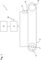
- an endless conveyor belt 2 is deflected at one end to run around a deflection roller 8 and at the other end to a drive roller of a drive unit 3 .
- the drive unit 3 drives the conveyor belt 2 by means of a servo motor.
- the servomotor has an incremental encoder 7 for detecting the respective setting position and is controlled by a control unit 4, which continuously regulates the rotational speed of the servomotor and continuously receives data from the incremental encoder 7.
- a switching flag 6 is fixed to a surface of the conveyor belt 2 and can be detected by a sensor 5 .
- the switch lug 6 can of course also be integrated inside the conveyor belt 2 or one or more elements thereof and can be detected inductively, for example.
- the sensor 5 is arranged along the load side of the conveyor belt 2 at the end of the conveyor belt 2 facing away from the drive unit 3 in the area of the deflection roller 8 and is directed towards the conveyor belt 2 in such a way that the switching flag 6 can be detected with it.
- the sensor 6 is also connected to the control unit 4 and continuously sends the detection of the switch lug 6 to the control unit 4.
- This switch lug 6 can alternatively also be a tool or tool part, for example a guide and/or forming finger.
- the control unit 4 is a programmable logic controller which has a user interface 9 for operation and for the output of information.
- the control unit 4 includes an interface 10 for programming using an external device and/or for coupling a plurality of control units 4, for example when a plurality of conveyor belts 2 are arranged one behind the other or parallel to one another.
- the associated angle of rotation value or incremental value of the incremental encoder 7 is stored in the control unit 4 as a reference value immediately after the installation of a new conveyor belt 2 when the switching flag 6 is detected by the sensor 5 during operation.
- the subsequent operation of the device 1 is regularly or continuously at a Detection of the switching flag 6 again detects the angle of rotation value or incremental value of the drive unit 3 and compared with the reference value. If the conveyor belt stretches, the switching flag 6 will reach the sensor 5 somewhat later, as a result of which the associated angle of rotation value or incremental value will also change.
- the elongation of the conveyor belt 2 can be calculated from the difference between the two values, the reference value and the currently measured angle of rotation value.
- the resolution of the measurement depends on the resolution of the incremental encoder, the number of motor revolutions for one revolution of the conveyor belt 2 and the length of the conveyor belt 2.
- the stretching or elongation of the conveyor belt 2 is monitored in the control unit 4 and a warning or a request to replace the conveyor belt 2 is output on the user interface 9 when a previously defined limit value is reached.
- the current elongation of the conveyor belt 2 can also be displayed continuously on the user interface 9 .
- a varying stretching of the conveyor belt 2 can occur not only due to wear and tear or aging, but also due to a different load with objects to be transported.
- a dynamic control of the drive unit 3 is a dynamic control of the drive unit 3 and thus it is possible to maintain a constant speed of the conveyor belt 2 or one that is adapted to another conveyor belt.
Landscapes
- Engineering & Computer Science (AREA)
- Mechanical Engineering (AREA)
- Control Of Conveyors (AREA)
Claims (13)
- Dispositif de transport de récipients ou d'emballages (1), comprenant- un élément de transport (2) tournant en continu,- une unité d'entraînement (3) pour l'entraînement de l'élément de transport (2) tournant,- une unité de commande (4) pour la commande de l'unité d'entraînement (3),- au moins un capteur stationnaire (5) pour la détection au moins d'une marque de position (6) de l'élément de transport (2),dans lequel- l'unité d'entraînement (3) présente un capteur d'angle de rotation (7) et- dans lequelun second élément de transport tournant en continu est prévu, dans lequel l'unité de commande (4) du premier élément de transport (2) est conçue afin de communiquer avec une unité de commande du second élément de transport,ou de recevoir des données d'un capteur d'angle de rotation et/ou d'un capteur du second élément de transport afin de synchroniser les vitesses de deux éléments de transport (2),caractérisé en ce que l'unité de commande (4) est reliée au capteur d'angle de rotation (7) ainsi qu'au capteur (5) de telle manière qu'au moyen des données du capteur d'angle de rotation (7) ainsi que du capteur (5), l'unité d'entraînement (3) puisse être commandée et/ou une expansion de l'élément de transport (2) puisse être calculée.
- Dispositif selon la revendication 1, caractérisé par précisément un capteur (5) par élément de transport (2).
- Dispositif selon la revendication 1 ou 2, caractérisé par précisément une marque de position (6) par élément de transport (2).
- Dispositif selon l'une ou plusieurs quelconques des revendications précédentes, caractérisé en ce qu'au moins deux capteurs (5) identiques sont agencés en déport l'un de l'autre le long de l'élément de transport (2) et coagissent avec l'unité de commande (4) de telle manière que les données de chaque capteur (5) puissent être traitées avec des données du capteur d'angle de rotation (7) afin de permettre une détermination définie par sections de l'expansion de l'élément de transport (2) et/ou une commande de vitesse dynamique définie par sections de l'unité d'entraînement (3).
- Dispositif selon l'une ou plusieurs quelconques des revendications précédentes, caractérisé en ce que la distance du capteur (5) à l'unité d'entraînement (3) correspond au moins à 95 % de la longueur du brin sous charge de l'élément de transport (2).
- Dispositif selon l'une ou plusieurs quelconques des revendications précédentes, caractérisé en ce que la marque de position (6) est formée par un talon de commutation fixé à l'élément de transport (2).
- Dispositif selon l'une ou plusieurs quelconques des revendications précédentes, caractérisé en ce que le premier élément de transport (2) est agencé au niveau du second élément de transport de telle manière que des récipients ou des emballages puissent être transmis du premier au second élément de transport (2).
- Dispositif selon l'une ou plusieurs quelconques des revendications précédentes, caractérisé en ce que le second élément de transport tournant en continu est agencé au moins par sections parallèlement au premier élément de transport (2).
- Procédé de commande et de surveillance d'un dispositif de transport, avec un élément de transport (2) tournant en continu entraîné par une unité d'entraînement (3) avec un capteur d'angle de rotation (7) ainsi qu'un capteur (5) stationnaire pour la détection d'une marque de position (6) de l'élément de transport (2), en particulier pour un dispositif (1) selon l'une ou plusieurs quelconques des revendications précédentes, avec les étapes suivantes :- la détermination d'un premier angle de rotation au moyen du capteur d'angle de rotation (7) lors d'une détection de la marque de position (6) par le capteur (5) et l'enregistrement dans une unité de commande (4) en tant qu'angle de rotation de référence,- la détermination au moins d'un autre angle de rotation pour une nouvelle détection de la marque de position (6) par le capteur (5) et la transmission à l'unité de commande (4) ainsi que- la comparaison de l'angle de rotation détecté avec l'angle de rotation de référence dans l'unité de commande (4) ainsi que la régulation de la vitesse de l'unité d'entraînement (3) et/ou la détermination de l'expansion de l'élément de transport (2),caractérisé en ce que
des données d'un capteur d'angle de rotation et/ou d'un capteur pour une marque de position d'un second élément de transport sont en outre aussi détectées au moyen de l'unité de commande (4) afin de réguler de manière adaptée au moins le premier élément de transport (2) au second élément de transport. - Procédé selon la revendication 9, caractérisé en ce que la vitesse de l'élément de transport (2) ainsi que de préférence au moins d'un autre élément de transport est régulée si besoin au moyen de l'unité de commande (4) respectivement par le biais de l'unité d'entraînement (3) de l'élément de transport (2).
- Procédé selon la revendication 9 ou 10, caractérisé en ce que pour plusieurs marques de position (6) agencées sur l'élément de transport (2) respectivement lors d'une détection par le capteur (5), un angle de rotation respectif est déterminé et par comparaison avec un angle de rotation de référence afférent, une régulation de vitesse dynamique de l'unité d'entraînement (3) et/ou une détermination de l'expansion pour la section respective de l'élément de transport (2) est entreprise.
- Procédé selon l'une ou plusieurs quelconques des revendications 9 à 10, caractérisé en ce que l'angle de rotation respectif est déterminé au moyen de capteurs (5) agencés par rapport à l'élément de transport (2) respectivement lors d'une détection d'une seule marque de position (6) et par comparaison avec un angle de rotation de référence respectif, une régulation de vitesse dynamique de l'unité d'entraînement (3) et/ou une détermination de l'expansion pour la section respective de l'élément de transport (2) est entreprise.
- Procédé selon l'une ou plusieurs quelconques des revendications 9 à 12, caractérisé en ce qu'au moins une influence transversale est détectée en même temps que la détermination de l'angle de rotation au moyen au moins d'un autre capteur et une correction est réalisée lors de la comparaison de l'angle de rotation détecté avec l'angle de rotation de référence au moyen de l'influence transversale mesurée.
Applications Claiming Priority (2)
| Application Number | Priority Date | Filing Date | Title |
|---|---|---|---|
| DE102016111421.9A DE102016111421A1 (de) | 2016-06-22 | 2016-06-22 | Transportvorrichtung und Verfahren zur Steuerung und Überwachung einer Transportvorrichtung |
| PCT/EP2017/062674 WO2017220281A1 (fr) | 2016-06-22 | 2017-05-24 | Dispositif de transport et procédé permettant de commander et de contrôler l'expansion d'un dispositif de transport |
Publications (2)
| Publication Number | Publication Date |
|---|---|
| EP3475196A1 EP3475196A1 (fr) | 2019-05-01 |
| EP3475196B1 true EP3475196B1 (fr) | 2023-03-22 |
Family
ID=58992839
Family Applications (1)
| Application Number | Title | Priority Date | Filing Date |
|---|---|---|---|
| EP17727169.9A Active EP3475196B1 (fr) | 2016-06-22 | 2017-05-24 | Dispositif de transport et procédé permettant de commander et de contrôler l'expansion d'un dispositif de transport |
Country Status (4)
| Country | Link |
|---|---|
| US (1) | US10538393B2 (fr) |
| EP (1) | EP3475196B1 (fr) |
| DE (1) | DE102016111421A1 (fr) |
| WO (1) | WO2017220281A1 (fr) |
Cited By (1)
| Publication number | Priority date | Publication date | Assignee | Title |
|---|---|---|---|---|
| US20230174315A1 (en) * | 2021-12-07 | 2023-06-08 | Laitram, L.L.C. | Measuring conveyor belt stretch |
Families Citing this family (11)
| Publication number | Priority date | Publication date | Assignee | Title |
|---|---|---|---|---|
| WO2017150508A1 (fr) * | 2016-02-29 | 2017-09-08 | 株式会社ブリヂストン | Dispositif de détection d'usure pour courroie de transporteur |
| JP6478234B2 (ja) * | 2017-06-26 | 2019-03-06 | ファナック株式会社 | ロボットシステム |
| ES2867385T3 (es) * | 2018-03-02 | 2021-10-20 | Afher Eurobelt S A | Sistema y método de monitorización de bandas transportadoras modulares |
| DE102018203814A1 (de) | 2018-03-13 | 2019-09-19 | Gebhardt Fördertechnik GmbH | Verfahren zur, vorzugsweise vorausschauenden, Instandhaltung eines automatisierten Fördersystems und entsprechendes Fördersystem |
| US11691824B2 (en) * | 2020-02-05 | 2023-07-04 | Cnh Industrial America Llc | Slip and wrap detection systems for a conveyor belt of an agricultural header |
| US12140423B2 (en) | 2020-05-08 | 2024-11-12 | BüHLER GMBH | Transport device having at least one chain |
| CN111620045A (zh) * | 2020-05-19 | 2020-09-04 | 广州智新智能科技有限公司 | 一种电机磁钢片上料装置 |
| KR102698495B1 (ko) * | 2021-05-28 | 2024-08-23 | (주)스포터 | 컨베이어 벨트의 표면 손상 감지 방법 및 시스템 |
| DE102021121656A1 (de) | 2021-08-20 | 2023-02-23 | Ulf Reinhardt | Systeme und Verfahren zur vorzeitigen Erkennung einer Havarie einer Fördereinheit eines Fördersystems eines Ofens und Ofen mit zumindest einem solchen System |
| WO2025068431A2 (fr) * | 2023-09-27 | 2025-04-03 | Beha Innovation Gmbh | Bande transporteuse pour transporter des produits alimentaires et système de traitement de produits alimentaires |
| DE102023129598B3 (de) * | 2023-10-26 | 2025-02-27 | Heye International Gmbh | Verfahren für eine Produktionsanlage, System und Produktionsanlage |
Citations (2)
| Publication number | Priority date | Publication date | Assignee | Title |
|---|---|---|---|---|
| US20080082206A1 (en) * | 2006-09-28 | 2008-04-03 | Yaskawa Electric America, Inc. | Automated conveying system |
| DE102011075994B3 (de) * | 2011-05-17 | 2012-07-19 | Lindauer Dornier Gesellschaft Mit Beschränkter Haftung | Vorrichtung und Verfahren zur Messung der Längung einer Kette, die endlos in der Vorrichtung umläuft |
Family Cites Families (14)
| Publication number | Priority date | Publication date | Assignee | Title |
|---|---|---|---|---|
| US1850336A (en) * | 1918-07-05 | 1932-03-22 | John Hays Hammond Jr | System for predirecting torpedoes |
| IT1190091B (it) * | 1985-04-26 | 1988-02-10 | Hauni Werke Koerber & Co Kg | Dispositivo per sorvegliare un trasportatore tessile per un filone dell'industria di lavorazione del tabacco |
| DE4115327A1 (de) | 1991-05-10 | 1992-11-12 | Joerg Henning Bender | Transportsystem zum transportieren von gegenstaenden entlang eines transportweges und steuerung fuer die antriebe eines derartigen transportsystems |
| JPH082565Y2 (ja) * | 1992-03-31 | 1996-01-29 | 株式会社椿本チエイン | 無端移動体の伸び測定装置 |
| US5563392A (en) | 1995-04-12 | 1996-10-08 | Patco Sales & Service, Inc. | Method and apparatus for monitoring wear of a continuous chain |
| DE19643997C2 (de) | 1996-10-31 | 2002-12-05 | Contitech Transportbandsysteme | Verfahren zur Überwachung eines Fördergurtes |
| GB2400090B (en) | 2003-04-05 | 2006-04-19 | Renold Plc | Chain wear monitoring method and apparatus |
| WO2005005292A1 (fr) | 2003-07-09 | 2005-01-20 | Bridgestone Corporation | Procede et dispositif pour mesurer l'elongation, l'usure et la temperature d'une bande transporteuse, feuille de caoutchoic magnetique, et procede de fabrication de cette feuille |
| WO2005023688A1 (fr) | 2003-09-03 | 2005-03-17 | Phoenix Ag | Dispositif de controle d'une installation de convoyage |
| US7275637B2 (en) * | 2005-02-24 | 2007-10-02 | Barry Charles Brown | Multi-channel conveyor belt condition monitoring |
| EP1850087B1 (fr) | 2006-04-25 | 2009-08-19 | Prüftechnik Dieter Busch Ag | Procédé et dispositf destiné à surveiller l'extension d'une chaîne d'entraînement |
| DE102010043057B4 (de) | 2010-10-28 | 2025-01-23 | Krones Aktiengesellschaft | Antriebsvorrichtung und Verfahren |
| PL2807096T3 (pl) * | 2012-01-23 | 2016-03-31 | Abb Schweiz Ag | System i sposób monitorowania stanu taśmy przenośnika |
| US8839949B2 (en) * | 2012-04-13 | 2014-09-23 | John Bean Technologies Corporation | Determination and correction of conveyor belt speed/location |
-
2016
- 2016-06-22 DE DE102016111421.9A patent/DE102016111421A1/de active Pending
-
2017
- 2017-05-24 EP EP17727169.9A patent/EP3475196B1/fr active Active
- 2017-05-24 WO PCT/EP2017/062674 patent/WO2017220281A1/fr not_active Ceased
- 2017-05-24 US US16/099,253 patent/US10538393B2/en active Active
Patent Citations (2)
| Publication number | Priority date | Publication date | Assignee | Title |
|---|---|---|---|---|
| US20080082206A1 (en) * | 2006-09-28 | 2008-04-03 | Yaskawa Electric America, Inc. | Automated conveying system |
| DE102011075994B3 (de) * | 2011-05-17 | 2012-07-19 | Lindauer Dornier Gesellschaft Mit Beschränkter Haftung | Vorrichtung und Verfahren zur Messung der Längung einer Kette, die endlos in der Vorrichtung umläuft |
Cited By (2)
| Publication number | Priority date | Publication date | Assignee | Title |
|---|---|---|---|---|
| US20230174315A1 (en) * | 2021-12-07 | 2023-06-08 | Laitram, L.L.C. | Measuring conveyor belt stretch |
| US12037201B2 (en) * | 2021-12-07 | 2024-07-16 | Laitram, L.L.C. | Measuring conveyor belt stretch |
Also Published As
| Publication number | Publication date |
|---|---|
| EP3475196A1 (fr) | 2019-05-01 |
| DE102016111421A1 (de) | 2017-12-28 |
| US10538393B2 (en) | 2020-01-21 |
| US20190210813A1 (en) | 2019-07-11 |
| WO2017220281A1 (fr) | 2017-12-28 |
Similar Documents
| Publication | Publication Date | Title |
|---|---|---|
| EP3475196B1 (fr) | Dispositif de transport et procédé permettant de commander et de contrôler l'expansion d'un dispositif de transport | |
| DE60302699T2 (de) | Fördergerät | |
| EP2804826B1 (fr) | Surveillance de la vitesse de déplacement d'une bande de matière | |
| EP2489612B1 (fr) | Agencement et procédé de surveillance d'une chaîne de transport pour un dispositif de transport et/ou d'enregistrement de l'industrie de traitement du tabac | |
| DE102011053145A1 (de) | Fehlerdiagnoseverfahren für Rollenförderer, Rollenförderer und Steuerung für Förderer | |
| DE102007028680A1 (de) | Gruppierungsstation | |
| EP3225571B1 (fr) | Dispositif de transport d'objets suspendus | |
| EP3898464B1 (fr) | Système de transport à unité à fonction de détection intégrée | |
| EP3384354B1 (fr) | Système d'entraînement électrique comprenant une unité d'accouplement soumise à un glissement | |
| EP3317619A1 (fr) | Procédé et dispositif de détermination d'une consommation d'énergie spécifique de convoyeurs à bande | |
| WO2019115456A1 (fr) | Procédé de surveillance d'état dans une installation de transport ainsi qu'unité de commande, tambour moteur et installation de transport pour la mise en oeuvre dudit procédé | |
| EP1607192B1 (fr) | Méthode et système pour estimer l'usure des articulations d'un bras de robot | |
| DE202010018479U1 (de) | Fördereinrichtung mit verbesserter Positionserkennung geförderter Objekte | |
| DE102007043557A1 (de) | Objekterfassung und Lichtgitter | |
| DE102014117787A1 (de) | Kettentestvorrichtung und Kettentestverfahren zum Testen eines Reibwerts zwischen einer Kette und einer Gleitleiste einer Transporteinrichtung | |
| EP3724107A1 (fr) | Dispositif servant à examiner une installation de convoyage ainsi qu'unité de commande, rouleau moteur et installation de convoyage et procédé | |
| DE102014103331B4 (de) | Steuerungsvorrichtung und -verfahren für eine Umreifungsmaschine | |
| WO2018091155A1 (fr) | Dispositif et procédé de détermination d'un coefficient d'occupation d'un dispositif de transport | |
| DE102018132138A1 (de) | Verfahren zur Detektion und Kommunikation von Fehlerzuständen in Ketten | |
| EP2918523B1 (fr) | Détecteur capacitif pour un rouleau et procédé de détection d'objets sur un transporteur à rouleaux | |
| DE102008046172B4 (de) | Vorrichtung und Verfahren zur Überwachung des Behältertransports bei einer Fördereinrichtung für Behälter und/oder Gebinde | |
| DE102011003061A1 (de) | Laserfeineinstellung der Flaschenposition | |
| WO2021224012A1 (fr) | Dispositif de transport comportant au moins une chaîne | |
| AT502975B1 (de) | Verfahren und vorrichtung zur diagnose einer kette in einem antriebssystem | |
| DE10304607A1 (de) | Verfahren und Vorrichtung zur Ermittlung des Vor- und/oder Nachlaufs von Wälzkörpern, die in einem Käfig eines Wälzlagers angeordnet sind |
Legal Events
| Date | Code | Title | Description |
|---|---|---|---|
| STAA | Information on the status of an ep patent application or granted ep patent |
Free format text: STATUS: UNKNOWN |
|
| STAA | Information on the status of an ep patent application or granted ep patent |
Free format text: STATUS: THE INTERNATIONAL PUBLICATION HAS BEEN MADE |
|
| PUAI | Public reference made under article 153(3) epc to a published international application that has entered the european phase |
Free format text: ORIGINAL CODE: 0009012 |
|
| STAA | Information on the status of an ep patent application or granted ep patent |
Free format text: STATUS: REQUEST FOR EXAMINATION WAS MADE |
|
| 17P | Request for examination filed |
Effective date: 20190122 |
|
| AK | Designated contracting states |
Kind code of ref document: A1 Designated state(s): AL AT BE BG CH CY CZ DE DK EE ES FI FR GB GR HR HU IE IS IT LI LT LU LV MC MK MT NL NO PL PT RO RS SE SI SK SM TR |
|
| AX | Request for extension of the european patent |
Extension state: BA ME |
|
| DAV | Request for validation of the european patent (deleted) | ||
| DAX | Request for extension of the european patent (deleted) | ||
| RAP1 | Party data changed (applicant data changed or rights of an application transferred) |
Owner name: KHS GMBH |
|
| GRAP | Despatch of communication of intention to grant a patent |
Free format text: ORIGINAL CODE: EPIDOSNIGR1 |
|
| STAA | Information on the status of an ep patent application or granted ep patent |
Free format text: STATUS: GRANT OF PATENT IS INTENDED |
|
| INTG | Intention to grant announced |
Effective date: 20221027 |
|
| GRAS | Grant fee paid |
Free format text: ORIGINAL CODE: EPIDOSNIGR3 |
|
| GRAA | (expected) grant |
Free format text: ORIGINAL CODE: 0009210 |
|
| STAA | Information on the status of an ep patent application or granted ep patent |
Free format text: STATUS: THE PATENT HAS BEEN GRANTED |
|
| AK | Designated contracting states |
Kind code of ref document: B1 Designated state(s): AL AT BE BG CH CY CZ DE DK EE ES FI FR GB GR HR HU IE IS IT LI LT LU LV MC MK MT NL NO PL PT RO RS SE SI SK SM TR |
|
| REG | Reference to a national code |
Ref country code: GB Ref legal event code: FG4D Free format text: NOT ENGLISH |
|
| REG | Reference to a national code |
Ref country code: CH Ref legal event code: EP |
|
| REG | Reference to a national code |
Ref country code: DE Ref legal event code: R096 Ref document number: 502017014522 Country of ref document: DE |
|
| REG | Reference to a national code |
Ref country code: IE Ref legal event code: FG4D Free format text: LANGUAGE OF EP DOCUMENT: GERMAN |
|
| REG | Reference to a national code |
Ref country code: AT Ref legal event code: REF Ref document number: 1555190 Country of ref document: AT Kind code of ref document: T Effective date: 20230415 |
|
| REG | Reference to a national code |
Ref country code: LT Ref legal event code: MG9D |
|
| REG | Reference to a national code |
Ref country code: NL Ref legal event code: MP Effective date: 20230322 |
|
| PG25 | Lapsed in a contracting state [announced via postgrant information from national office to epo] |
Ref country code: RS Free format text: LAPSE BECAUSE OF FAILURE TO SUBMIT A TRANSLATION OF THE DESCRIPTION OR TO PAY THE FEE WITHIN THE PRESCRIBED TIME-LIMIT Effective date: 20230322 Ref country code: NO Free format text: LAPSE BECAUSE OF FAILURE TO SUBMIT A TRANSLATION OF THE DESCRIPTION OR TO PAY THE FEE WITHIN THE PRESCRIBED TIME-LIMIT Effective date: 20230622 Ref country code: LV Free format text: LAPSE BECAUSE OF FAILURE TO SUBMIT A TRANSLATION OF THE DESCRIPTION OR TO PAY THE FEE WITHIN THE PRESCRIBED TIME-LIMIT Effective date: 20230322 Ref country code: LT Free format text: LAPSE BECAUSE OF FAILURE TO SUBMIT A TRANSLATION OF THE DESCRIPTION OR TO PAY THE FEE WITHIN THE PRESCRIBED TIME-LIMIT Effective date: 20230322 Ref country code: HR Free format text: LAPSE BECAUSE OF FAILURE TO SUBMIT A TRANSLATION OF THE DESCRIPTION OR TO PAY THE FEE WITHIN THE PRESCRIBED TIME-LIMIT Effective date: 20230322 |
|
| PG25 | Lapsed in a contracting state [announced via postgrant information from national office to epo] |
Ref country code: SE Free format text: LAPSE BECAUSE OF FAILURE TO SUBMIT A TRANSLATION OF THE DESCRIPTION OR TO PAY THE FEE WITHIN THE PRESCRIBED TIME-LIMIT Effective date: 20230322 Ref country code: NL Free format text: LAPSE BECAUSE OF FAILURE TO SUBMIT A TRANSLATION OF THE DESCRIPTION OR TO PAY THE FEE WITHIN THE PRESCRIBED TIME-LIMIT Effective date: 20230322 Ref country code: GR Free format text: LAPSE BECAUSE OF FAILURE TO SUBMIT A TRANSLATION OF THE DESCRIPTION OR TO PAY THE FEE WITHIN THE PRESCRIBED TIME-LIMIT Effective date: 20230623 Ref country code: FI Free format text: LAPSE BECAUSE OF FAILURE TO SUBMIT A TRANSLATION OF THE DESCRIPTION OR TO PAY THE FEE WITHIN THE PRESCRIBED TIME-LIMIT Effective date: 20230322 |
|
| PG25 | Lapsed in a contracting state [announced via postgrant information from national office to epo] |
Ref country code: SM Free format text: LAPSE BECAUSE OF FAILURE TO SUBMIT A TRANSLATION OF THE DESCRIPTION OR TO PAY THE FEE WITHIN THE PRESCRIBED TIME-LIMIT Effective date: 20230322 Ref country code: RO Free format text: LAPSE BECAUSE OF FAILURE TO SUBMIT A TRANSLATION OF THE DESCRIPTION OR TO PAY THE FEE WITHIN THE PRESCRIBED TIME-LIMIT Effective date: 20230322 Ref country code: PT Free format text: LAPSE BECAUSE OF FAILURE TO SUBMIT A TRANSLATION OF THE DESCRIPTION OR TO PAY THE FEE WITHIN THE PRESCRIBED TIME-LIMIT Effective date: 20230724 Ref country code: ES Free format text: LAPSE BECAUSE OF FAILURE TO SUBMIT A TRANSLATION OF THE DESCRIPTION OR TO PAY THE FEE WITHIN THE PRESCRIBED TIME-LIMIT Effective date: 20230322 Ref country code: EE Free format text: LAPSE BECAUSE OF FAILURE TO SUBMIT A TRANSLATION OF THE DESCRIPTION OR TO PAY THE FEE WITHIN THE PRESCRIBED TIME-LIMIT Effective date: 20230322 |
|
| PG25 | Lapsed in a contracting state [announced via postgrant information from national office to epo] |
Ref country code: SK Free format text: LAPSE BECAUSE OF FAILURE TO SUBMIT A TRANSLATION OF THE DESCRIPTION OR TO PAY THE FEE WITHIN THE PRESCRIBED TIME-LIMIT Effective date: 20230322 Ref country code: PL Free format text: LAPSE BECAUSE OF FAILURE TO SUBMIT A TRANSLATION OF THE DESCRIPTION OR TO PAY THE FEE WITHIN THE PRESCRIBED TIME-LIMIT Effective date: 20230322 Ref country code: IS Free format text: LAPSE BECAUSE OF FAILURE TO SUBMIT A TRANSLATION OF THE DESCRIPTION OR TO PAY THE FEE WITHIN THE PRESCRIBED TIME-LIMIT Effective date: 20230722 |
|
| REG | Reference to a national code |
Ref country code: CH Ref legal event code: PL |
|
| REG | Reference to a national code |
Ref country code: DE Ref legal event code: R097 Ref document number: 502017014522 Country of ref document: DE |
|
| PG25 | Lapsed in a contracting state [announced via postgrant information from national office to epo] |
Ref country code: MC Free format text: LAPSE BECAUSE OF FAILURE TO SUBMIT A TRANSLATION OF THE DESCRIPTION OR TO PAY THE FEE WITHIN THE PRESCRIBED TIME-LIMIT Effective date: 20230322 |
|
| PLBE | No opposition filed within time limit |
Free format text: ORIGINAL CODE: 0009261 |
|
| STAA | Information on the status of an ep patent application or granted ep patent |
Free format text: STATUS: NO OPPOSITION FILED WITHIN TIME LIMIT |
|
| REG | Reference to a national code |
Ref country code: BE Ref legal event code: MM Effective date: 20230531 |
|
| PG25 | Lapsed in a contracting state [announced via postgrant information from national office to epo] |
Ref country code: SI Free format text: LAPSE BECAUSE OF FAILURE TO SUBMIT A TRANSLATION OF THE DESCRIPTION OR TO PAY THE FEE WITHIN THE PRESCRIBED TIME-LIMIT Effective date: 20230322 Ref country code: MC Free format text: LAPSE BECAUSE OF FAILURE TO SUBMIT A TRANSLATION OF THE DESCRIPTION OR TO PAY THE FEE WITHIN THE PRESCRIBED TIME-LIMIT Effective date: 20230322 Ref country code: LU Free format text: LAPSE BECAUSE OF NON-PAYMENT OF DUE FEES Effective date: 20230524 Ref country code: LI Free format text: LAPSE BECAUSE OF NON-PAYMENT OF DUE FEES Effective date: 20230531 Ref country code: DK Free format text: LAPSE BECAUSE OF FAILURE TO SUBMIT A TRANSLATION OF THE DESCRIPTION OR TO PAY THE FEE WITHIN THE PRESCRIBED TIME-LIMIT Effective date: 20230322 Ref country code: CZ Free format text: LAPSE BECAUSE OF FAILURE TO SUBMIT A TRANSLATION OF THE DESCRIPTION OR TO PAY THE FEE WITHIN THE PRESCRIBED TIME-LIMIT Effective date: 20230322 Ref country code: CH Free format text: LAPSE BECAUSE OF NON-PAYMENT OF DUE FEES Effective date: 20230531 |
|
| 26N | No opposition filed |
Effective date: 20240102 |
|
| GBPC | Gb: european patent ceased through non-payment of renewal fee |
Effective date: 20230622 |
|
| REG | Reference to a national code |
Ref country code: IE Ref legal event code: MM4A |
|
| PG25 | Lapsed in a contracting state [announced via postgrant information from national office to epo] |
Ref country code: IE Free format text: LAPSE BECAUSE OF NON-PAYMENT OF DUE FEES Effective date: 20230524 |
|
| PG25 | Lapsed in a contracting state [announced via postgrant information from national office to epo] |
Ref country code: IE Free format text: LAPSE BECAUSE OF NON-PAYMENT OF DUE FEES Effective date: 20230524 Ref country code: GB Free format text: LAPSE BECAUSE OF NON-PAYMENT OF DUE FEES Effective date: 20230622 |
|
| PG25 | Lapsed in a contracting state [announced via postgrant information from national office to epo] |
Ref country code: BE Free format text: LAPSE BECAUSE OF NON-PAYMENT OF DUE FEES Effective date: 20230531 |
|
| PG25 | Lapsed in a contracting state [announced via postgrant information from national office to epo] |
Ref country code: BG Free format text: LAPSE BECAUSE OF FAILURE TO SUBMIT A TRANSLATION OF THE DESCRIPTION OR TO PAY THE FEE WITHIN THE PRESCRIBED TIME-LIMIT Effective date: 20230322 |
|
| PG25 | Lapsed in a contracting state [announced via postgrant information from national office to epo] |
Ref country code: BG Free format text: LAPSE BECAUSE OF FAILURE TO SUBMIT A TRANSLATION OF THE DESCRIPTION OR TO PAY THE FEE WITHIN THE PRESCRIBED TIME-LIMIT Effective date: 20230322 |
|
| PGFP | Annual fee paid to national office [announced via postgrant information from national office to epo] |
Ref country code: DE Payment date: 20250521 Year of fee payment: 9 |
|
| PGFP | Annual fee paid to national office [announced via postgrant information from national office to epo] |
Ref country code: IT Payment date: 20250527 Year of fee payment: 9 |
|
| PGFP | Annual fee paid to national office [announced via postgrant information from national office to epo] |
Ref country code: FR Payment date: 20250528 Year of fee payment: 9 |
|
| PGFP | Annual fee paid to national office [announced via postgrant information from national office to epo] |
Ref country code: AT Payment date: 20250522 Year of fee payment: 9 |
|
| PG25 | Lapsed in a contracting state [announced via postgrant information from national office to epo] |
Ref country code: CY Free format text: LAPSE BECAUSE OF FAILURE TO SUBMIT A TRANSLATION OF THE DESCRIPTION OR TO PAY THE FEE WITHIN THE PRESCRIBED TIME-LIMIT; INVALID AB INITIO Effective date: 20170524 |
|
| PG25 | Lapsed in a contracting state [announced via postgrant information from national office to epo] |
Ref country code: HU Free format text: LAPSE BECAUSE OF FAILURE TO SUBMIT A TRANSLATION OF THE DESCRIPTION OR TO PAY THE FEE WITHIN THE PRESCRIBED TIME-LIMIT; INVALID AB INITIO Effective date: 20170524 |
|
| PG25 | Lapsed in a contracting state [announced via postgrant information from national office to epo] |
Ref country code: TR Free format text: LAPSE BECAUSE OF FAILURE TO SUBMIT A TRANSLATION OF THE DESCRIPTION OR TO PAY THE FEE WITHIN THE PRESCRIBED TIME-LIMIT Effective date: 20230322 |
|
| P01 | Opt-out of the competence of the unified patent court (upc) registered |
Free format text: CASE NUMBER: UPC_APP_0014570_3475196/2025 Effective date: 20251125 |