EP2912213B1 - Système d'alimentation à la demande en oxy-hydrogène comme carburant pour moteurs à combustion interne - Google Patents
Système d'alimentation à la demande en oxy-hydrogène comme carburant pour moteurs à combustion interne Download PDFInfo
- Publication number
- EP2912213B1 EP2912213B1 EP14746009.1A EP14746009A EP2912213B1 EP 2912213 B1 EP2912213 B1 EP 2912213B1 EP 14746009 A EP14746009 A EP 14746009A EP 2912213 B1 EP2912213 B1 EP 2912213B1
- Authority
- EP
- European Patent Office
- Prior art keywords
- oxy
- hydrogen
- fuel system
- demand
- hydrogen fuel
- Prior art date
- Legal status (The legal status is an assumption and is not a legal conclusion. Google has not performed a legal analysis and makes no representation as to the accuracy of the status listed.)
- Not-in-force
Links
Images

Classifications
-
- G—PHYSICS
- G01—MEASURING; TESTING
- G01N—INVESTIGATING OR ANALYSING MATERIALS BY DETERMINING THEIR CHEMICAL OR PHYSICAL PROPERTIES
- G01N21/00—Investigating or analysing materials by the use of optical means, i.e. using sub-millimetre waves, infrared, visible or ultraviolet light
- G01N21/17—Systems in which incident light is modified in accordance with the properties of the material investigated
- G01N21/25—Colour; Spectral properties, i.e. comparison of effect of material on the light at two or more different wavelengths or wavelength bands
- G01N21/31—Investigating relative effect of material at wavelengths characteristic of specific elements or molecules, e.g. atomic absorption spectrometry
- G01N21/35—Investigating relative effect of material at wavelengths characteristic of specific elements or molecules, e.g. atomic absorption spectrometry using infrared light
- G01N21/3504—Investigating relative effect of material at wavelengths characteristic of specific elements or molecules, e.g. atomic absorption spectrometry using infrared light for analysing gases, e.g. multi-gas analysis
-
- G—PHYSICS
- G01—MEASURING; TESTING
- G01N—INVESTIGATING OR ANALYSING MATERIALS BY DETERMINING THEIR CHEMICAL OR PHYSICAL PROPERTIES
- G01N33/00—Investigating or analysing materials by specific methods not covered by groups G01N1/00 - G01N31/00
- G01N33/0004—Gaseous mixtures, e.g. polluted air
- G01N33/0009—General constructional details of gas analysers, e.g. portable test equipment
- G01N33/0027—General constructional details of gas analysers, e.g. portable test equipment concerning the detector
- G01N33/0036—General constructional details of gas analysers, e.g. portable test equipment concerning the detector specially adapted to detect a particular component
-
- C—CHEMISTRY; METALLURGY
- C25—ELECTROLYTIC OR ELECTROPHORETIC PROCESSES; APPARATUS THEREFOR
- C25B—ELECTROLYTIC OR ELECTROPHORETIC PROCESSES FOR THE PRODUCTION OF COMPOUNDS OR NON-METALS; APPARATUS THEREFOR
- C25B1/00—Electrolytic production of inorganic compounds or non-metals
- C25B1/01—Products
- C25B1/02—Hydrogen or oxygen
- C25B1/04—Hydrogen or oxygen by electrolysis of water
-
- G—PHYSICS
- G06—COMPUTING OR CALCULATING; COUNTING
- G06Q—INFORMATION AND COMMUNICATION TECHNOLOGY [ICT] SPECIALLY ADAPTED FOR ADMINISTRATIVE, COMMERCIAL, FINANCIAL, MANAGERIAL OR SUPERVISORY PURPOSES; SYSTEMS OR METHODS SPECIALLY ADAPTED FOR ADMINISTRATIVE, COMMERCIAL, FINANCIAL, MANAGERIAL OR SUPERVISORY PURPOSES, NOT OTHERWISE PROVIDED FOR
- G06Q30/00—Commerce
- G06Q30/06—Buying, selling or leasing transactions
- G06Q30/0601—Electronic shopping [e-shopping]
- G06Q30/0613—Electronic shopping [e-shopping] using intermediate agents
-
- G—PHYSICS
- G01—MEASURING; TESTING
- G01N—INVESTIGATING OR ANALYSING MATERIALS BY DETERMINING THEIR CHEMICAL OR PHYSICAL PROPERTIES
- G01N21/00—Investigating or analysing materials by the use of optical means, i.e. using sub-millimetre waves, infrared, visible or ultraviolet light
- G01N21/17—Systems in which incident light is modified in accordance with the properties of the material investigated
- G01N21/25—Colour; Spectral properties, i.e. comparison of effect of material on the light at two or more different wavelengths or wavelength bands
- G01N21/31—Investigating relative effect of material at wavelengths characteristic of specific elements or molecules, e.g. atomic absorption spectrometry
- G01N21/39—Investigating relative effect of material at wavelengths characteristic of specific elements or molecules, e.g. atomic absorption spectrometry using tunable lasers
- G01N2021/396—Type of laser source
- G01N2021/399—Diode laser
-
- G—PHYSICS
- G01—MEASURING; TESTING
- G01N—INVESTIGATING OR ANALYSING MATERIALS BY DETERMINING THEIR CHEMICAL OR PHYSICAL PROPERTIES
- G01N21/00—Investigating or analysing materials by the use of optical means, i.e. using sub-millimetre waves, infrared, visible or ultraviolet light
- G01N21/84—Systems specially adapted for particular applications
- G01N21/85—Investigating moving fluids or granular solids
- G01N2021/8578—Gaseous flow
-
- G—PHYSICS
- G01—MEASURING; TESTING
- G01N—INVESTIGATING OR ANALYSING MATERIALS BY DETERMINING THEIR CHEMICAL OR PHYSICAL PROPERTIES
- G01N2201/00—Features of devices classified in G01N21/00
- G01N2201/06—Illumination; Optics
- G01N2201/063—Illuminating optical parts
- G01N2201/0634—Diffuse illumination
-
- Y—GENERAL TAGGING OF NEW TECHNOLOGICAL DEVELOPMENTS; GENERAL TAGGING OF CROSS-SECTIONAL TECHNOLOGIES SPANNING OVER SEVERAL SECTIONS OF THE IPC; TECHNICAL SUBJECTS COVERED BY FORMER USPC CROSS-REFERENCE ART COLLECTIONS [XRACs] AND DIGESTS
- Y02—TECHNOLOGIES OR APPLICATIONS FOR MITIGATION OR ADAPTATION AGAINST CLIMATE CHANGE
- Y02E—REDUCTION OF GREENHOUSE GAS [GHG] EMISSIONS, RELATED TO ENERGY GENERATION, TRANSMISSION OR DISTRIBUTION
- Y02E60/00—Enabling technologies; Technologies with a potential or indirect contribution to GHG emissions mitigation
- Y02E60/30—Hydrogen technology
- Y02E60/36—Hydrogen production from non-carbon containing sources, e.g. by water electrolysis
Definitions
- the present invention generally relates to internal combustion engines. More particularly, the present invention relates to an on-demand electrolytically generated oxy-hydrogen fuel system which is incorporated into the fuel supply system of a standard internal combustion engine.
- ICE piston-based internal combustion engines
- oil is pre-mixed with fuel and air before the oil-fuel-air mixture is injected into the cylinder, where the oil/fuel/air mixture is ignited.
- atomized fuel is pre-mixed with air, compressed by the movement of the piston against the cylinder head, and ignited by a spark plug that causes the fuel to burn.
- fuel and air are pre-mixed, atomized, and injected into the cylinder.
- the fuel/air mixture is ignited by the combination of heat accumulated by the mass of the cylinder head and compression by the piston.
- the piston In each type of ICE engine, the piston is pushed downward against the crankshaft by the pressure exerted by the expansion of detonated fuel and air. Exhaust fumes are allowed to exit the cylinder when the rotation of the crankshaft and camshaft opens the exhaust valve.
- the movement of the piston on the subsequent oscillation creates a vacuum in the cylinder which draws additional fresh oil/fuel/air into the cylinder, thereby simultaneously pushing the remaining exhaust out the exhaust port and driving by-pass gases out of the crankcase through the positive crankcase ventilation (PCV) valve. Momentum drives the piston back into the compression stroke as the process repeats itself.
- PCV positive crankcase ventilation
- oil lubrication of the crankshaft and connecting rod bearings is supported by an oil distribution system that is separated from the fuel/air mixture.
- the fuel/air mixture in the intake manifold is drawn into the combustion chamber where it is ignited by either spark plugs (in a gasoline engine) or compression.
- the combustion chamber in both gasoline and diesel engines is largely isolated from the crankcase by a set of piston rings that are disposed around an outer diameter of each piston within each piston cylinder.
- the seals are included in the design of the engine as a way of containing the pressure exerted by each ignition event and forcing the exhaust gases to exit via the exhaust port rather than allowing the hot, pressurized gases to escape into the crankcase.
- crankcase oil intended to lubricate the cylinder are instead drawn into the combustion chamber and burned during the combustion process. This is true in both gasoline and diesel powered engines.
- combustion waste gases comprising unburned fuel and exhaust gases in the combustion chamber simultaneously pass the piston rings and enter the crankcase.
- the waste gases entering the crankcase are commonly referred to as "blow-by" or “blow-by gas”.
- Blow-by gases mainly consist of contaminants such as hydrocarbons (unburned fuel), carbon dioxide and/or water vapor, all of which serve to contaminate the oil held in the engine crankcase.
- the quantity of blow-by gases which leak into the crankcase can be several times that of the concentration of hydrocarbons in the intake manifold. Simply venting these gases to the atmosphere increases air pollution.
- crankcase ventilation systems evacuate blow-by gases from the crankcase via a device referred to as a positive crankcase ventilation (PCV) valve.
- PCV positive crankcase ventilation
- the PCV valve re-circulates (i.e. vents) blow-by gases from the crankcase back into the intake manifold to be burned again with a fresh supply of air/fuel during subsequent combustion cycles. This is particularly desirable as the harmful blow-by gases are not simply vented to the atmosphere.
- On-Board Diagnostics refers to early vehicle self-diagnostic systems and reporting capabilities developed and installed in automobiles by manufacturers. OBD systems provide current state information for various vehicle subsystems. The quantity of diagnostic information available via OBD has varied widely since the introduction of on-board computers to automobiles in the early 1980s. OBD originally illuminated a malfunction indicator light (MIL) for a detected problem, but did not provide information regarding the nature of the problem. Modern OBD implementations use a standardized highspeed digital communications port to provide real-time data in combination with standardized series of diagnostic trouble codes (DTCs) to facilitate rapid identification of malfunctions and the corresponding remedies from within the vehicle.
- DTCs diagnostic trouble codes
- CARB California Air Resources Board
- OBD-I The California Air Resources Board
- the aim of CARB was to encourage automobile manufacturers to design reliable emission control systems.
- CARB envisioned lowering vehicle emissions in California by denying registration to vehicles that did not pass the CARB vehicle emission standards.
- OBD-I did not succeed at the time because the infrastructure for testing and reporting emissions-specific diagnostic information was not standardized or widely accepted.
- Technical difficulties in obtaining standardized and reliable emission information from all vehicles resulted in a systemic inability to effectively implement an annual emissions testing program.
- OBD-II became more sophisticated after the initial implementation of OBD-I.
- OBD-II was a new standard introduced in the mid-1990s that implemented a new set of standards and practices developed by the Society of Automotive Engineers (SAE). These standards were eventually adopted by the EPA and CARB.
- SAE Society of Automotive Engineers
- OBD-II incorporates enhanced features that provide better engine monitoring technologies.
- OBD-II also monitors chassis parts, body and accessory devices, and includes an automobile diagnostic control network.
- OBD-II improved upon OBD-I in both capability and standardization.
- OBD-II specifies the type of diagnostic connector, pin configuration, electrical signaling protocols, messaging format and provides an extensible list of diagnostic trouble codes (DTCs).
- DTCs diagnostic trouble codes
- OBD-II also monitors a specific list of vehicle parameters and encodes performance data for each of those parameters. Thus, a single device can query the on-board computer(s) in any vehicle. This simplification of reporting diagnostic data led to the feasibility of the
- HALO Hydrogen-Assisted Lean Operation of Natural Gas-Fueld Reciprocating Engines
- NOx values of 10 ppm (0.07 g/bhp-hr NO) for 8% (LHV H2/LHV CH4) supplementation at an exhaust O2 level of 10% were demonstrated, which is a 98% NOx emissions reduction compared to the leanest unsupplemented operating condition.
- Spark ignition energy reduction (which will increase ignition system life) was carried out at an oxygen level of 9 %, leading to a NOx emission level of 28 ppm (0.13 g/bhp-hr NO).
- spark ignition energy reduction testing found that spark energy could be reduced 22% (from 1 51 mJ supplied to the coil) with 13% (LHV H2/LHV CH4) oxy-hydrogen supplementation, and even further reduced 27% with 17% oxy-hydrogen supplementation, with no reportable effect on NOx emissions for these conditions and with stable engine torque output. Another important result is that the combustion duration was shown to be only a function of oxy-hydrogen supplementation, not a function of ignition energy (until the ignitability limit was reached). The next logical step leading from these promising results is to see how much the spark energy reduction translates into increase in spark plug life, which may be accomplished by durability testing.” In 2006, Mr. Dennis J. Klein and Dr. Rugerro M.
- the current invention recognizes the need for an oxy-hydrogen gas generator system which supplies computer-controlled stoichiometric volumes of gas on-demand, does not require generation and storage of oxy-hydrogen gas for later use, is compatible with the operating parameters intrinsic to electronically controlled engine management modules, and does not generate a significant quantity of water vapor.
- the present invention fulfills these needs, and provides other related advantages.
- the present invention is directed to an on-demand oxy-hydrogen fuel system for internal combustion engines, as defined in independent claim 1, which comprises an oxy-hydrogen generator.
- the oxy-hydrogen generator comprises a fluid reservoir containing an electrolyte solution.
- a cap configured to cover and seal, i.e., sealingly engage, an opening on the fluid reservoir has a positive terminal, a negative terminal, and a gas outlet.
- the gas outlet is in fluid communication with an interior of the fluid reservoir.
- a pair of electrode plates are attached to the cap and extend into the interior of the fluid reservoir so as to be at least partially submerged in the electrolyte solution. One of the pair of electrode plates is electrically coupled to the positive terminal and the other of the pair of electrode plates is electrically coupled to the negative terminal.
- Each of the pair of electrode plates preferably comprises a series of metal plates.
- the series of metal plates made from a metal selected from the group consisting of zinc, cadmium, gold, platinum, and palladium.
- the series of metal plates may also comprise a catalyst in an electrolysis reaction of water.
- the electrolyte solution preferably comprises water mixed with an electrolytic salt, such as potassium nitrate, sodium bicarbonate, or the like.
- the oxy-hydrogen generator preferably comprises a secondary reservoir connected to the fluid reservoir by appropriate tubing or piping.
- the secondary reservoir contains additional electrolyte solution.
- the generator may also include a sensor configured to detect and regulate the level of the electrolyte solution in the fluid reservoir by supplying additional solution from the secondary reservoir.
- an on-demand oxy-hydrogen fuel system for an internal combustion engine comprises a oxy-hydrogen generator as described above configured to electrolyze the electrolyte solution.
- the gas outlet on the oxy-hydrogen generator is configured to release oxy-hydrogen gas produced by the electrolysis of the electrolyte solution.
- the gas outlet is fluidly coupled to an intake manifold on the engine.
- a microcontroller is operably connected to the oxy-hydrogen generator and configured to selectively power the oxy-hydrogen generator in response to a demand for oxy-hydrogen.
- the gas outlet is fluidly coupled to a pollution control system configured to recycle blow-by gasses from a crankcase on the internal combustion engine to the intake manifold.
- the pollution control system preferably comprises a PCV valve in line with a vent line from the crankcase and a blow-by return line to the intake manifold.
- the gas outlet may be coupled to the vent line from the crankcase, the blow-by return line to the intake manifold, or the PCV valve.
- the microcontroller is also operably connected to the PCV valve and configured to regulate a flow rate of blow-by gasses through the PCV valve.
- the positive and negative terminals of the oxy-hydrogen generator are preferably electrically connected to a power source of the engine.
- the power source may comprise a battery or an alternator.
- the present invention is directed to an on-demand oxy-hydrogen fuel system which is incorporated into a standard internal combustion engine.
- the oxy-hydrogen generator embodying the present invention is referred to generally by the reference number 100.
- the oxy-hydrogen generator 100 of the present invention is incorporated into a pollution control system, such as that illustrated and described in United States Patent No. 8,360,038 , or United States application serial number 61/754,384 .
- the oxy-hydrogen generated by the system of the present invention is added to blow-by gases regulated by a microcontroller 10 and a PCV valve 12.
- the microcontroller 10 is preferably mounted under a hood 14 of an automobile 16.
- the microcontroller 10 is electrically coupled to one or more of a plurality of sensors that monitor and measure real-time operating conditions and performance of the automobile 16.
- the microcontroller 10 regulates the flow rate of blow-by gases by regulating the engine vacuum in a combustion engine through digital control of a PCV valve 12.
- the microcontroller 10 receives real-time input from sensors that might include an engine temperature sensor 18, a spark plug sensor 20, a battery sensor 22, a PCV valve sensor 24, and engine RPM sensor 26, an accelerometer sensor 28, and an exhaust sensor 30. Data obtained from the sensors 18, 20, 22, 24, 26, 28, and 30 by the microcontroller 10 is used to regulate the PCV valve 12, as described in more detail below.
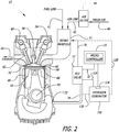
- FIGURE 2 is a schematic illustrating operation of the microcontroller 10 in conjunction with the PCV valve 12 in a car engine 15.
- the PCV valve 12 is disposed between a crankcase 49, of an engine 1 5, and an intake manifold 51.
- the intake manifold 51 receives a mixture of fuel and air via a fuel line 41 and an air line 42, respectively.
- An air filter 44 may be disposed between the air line 42 and an air intake line 46 to filter fresh air before mixing with fuel in the intake manifold 51.
- the air/fuel mixture in the intake manifold 51 is delivered to a piston cylinder 48 as a piston 50 descends downward within the cylinder 48 from the top dead center. This creates a vacuum within a combustion chamber 52.
- an input camshaft 54 rotating at half the speed of the crankshaft 49 is designed to open an input valve 56 thereby subjecting the intake manifold 51 to the engine vacuum.
- fuel/air is drawn into the combustion chamber 52 from the intake manifold 51.
- the fuel/air in the combustion chamber 52 is ignited by a spark plug 58 (in a gasoline engine).
- the rapid expansion of the ignited fuel/air in the combustion chamber 52 causes depression of the piston 50 within the cylinder 48.
- an exhaust camshaft 60 opens an exhaust valve 62 to allow escape of the combustion gases from the combustion chamber 52 out an exhaust line 64.
- excess exhaust gases slip by a pair of piston rings 66 mounted in the head 68 of the piston 50.
- the PCV valve 12 is designed to vent these blow-by gases from the crankcase 49 to the intake manifold 51 to be recycled as fuel for the engine 15. This is accomplished by using the pressure differential between the crankcase 49 and the intake manifold 51.
- the blow-by gases exit the relatively higher pressure crankcase 49 through a vent 72 and travel through a vent line 74, the PCV valve 12, a blow-by return line 76 and into a relatively lower pressure intake manifold 51 coupled thereto.
- the quantity of blow-by gases vented from the crankcase 49 to the intake manifold 51 via the PCV valve 12 is digitally regulated by the microcontroller 10, which is connected to the PCV valve via connection wires 32.
- the microcontroller 10 is powered by a battery 11 and grounded at the ground connection 13.
- venting blow-by gases based on engine speed and other operating characteristics of an automobile decreases the quantity of hydrocarbons, carbon monoxide, nitrogen oxide and carbon dioxide emissions.
- the PCV valve 12 and microcontroller 10 recycle gases by burning them in the combustion cycle. No longer are large quantities of the contaminants expelled from the vehicle via the exhaust.
- the PCV valve 12 and microcontroller 10 are capable of reducing air pollution emissions for each automobile, increasing gas mileage per gallon, increasing horsepower performance, reducing engine wear (due to low carbon retention) and dramatically reducing the number of oil changes required.
- the microcontroller 10 functions in three states. First, upon ignition of the vehicle, the microcontroller 10 causes the solenoid 80 in the PCV valve 12 to stay closed, as described above. This is because the engine 15 of the vehicle produces large quantities of pollution while still heating up. Once the engine 15 is properly heated, it functions more efficiently and produces less pollution. At that point, the microcontroller 10 enters the next state and functions as a window switch based on the engine RPM. While the engine is operating with a certain RPM range, the microcontroller 10 causes the solenoid 80 in the PCV valve 12 to open. Once the engine falls out of that RPM range, the solenoid 80 in the PCV valve 12 closes again.
- the microcontroller 10 activates a timing sequence so the vehicle's on-board diagnostics is prevented from introducing too much fuel into the engine.
- This timing sequence can be programmed to any interval, but in the preferred embodiment the sequence causes the solenoid 80 in the PCV valve 12 to be open for two minutes, then closed for 10 minutes. This sequence is repeated indefinitely until the engine RPM falls out of the given range.
- microcontroller 10 While the logic of the preferred embodiment of the microcontroller 10 is based primarily on engine RPM, other embodiments of the microcontroller 10 may have logic based on other criteria. Such criteria may be engine temperature and engine torque, as well as crankcase pressure. Basing the microcontroller logic on these additional criteria makes for a control system that is more adjustable and programmable.
- the oxy-hydrogen generator 100 of the present invention is operably coupled to the microcontroller 10 and the PCV valve 12.
- the microcontroller 10 is used to selectively power the oxy-hydrogen generator 100, causing the oxy-hydrogen generator 100 to generate oxy-hydrogen and create a flow of oxy-hydrogen into the PCV valve and/or the intake manifold 51 with the blow-by gases from the crankcase.
- the produced oxy-hydrogen is approximately 180 octane, and thus provides a very efficient fuel source that can dramatically increase fuel efficiency and reduce emissions.
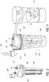
- the oxy-hydrogen generator 100 comprises a series of metal plates 104 and 106, comprising anode and cathode electrodes.
- the metallic plates 104 and 106 can comprise any known metallic plates or anodes or cathodes which can be used for electrolysis of a water solution into oxy-hydrogen gas.
- Plating metals include zinc, cadmium, gold, platinum, palladium, and the like.
- the metal plates may serve as a catalyst or promoter to facilitate the rate of the chemical reaction of the water being turned into oxy-hydrogen gas and oxygen.
- the metal plates comprising the anode and cathode 104 and 106 merely serve to conduct electricity through the water solution to perform the electrolysis and electrically convert the water molecules to oxy-hydrogen and oxygen gas.
- the oxy-hydrogen generator 100 includes a cap 108 which seals the top of a container 110. Electrodes or terminals 112 and 114, representing the cathode and anode, extend from electrical coupling to the plates 104 and 106 to the exterior of the cap 108 so as to be coupled to electrical wires from the electrical source of the internal combustion engine, such as the battery, alternator or the like.
- an electrolyte water solution is created, such as by adding an electrolytic salt - potassium nitrate, sodium bicarbonate (baking soda) or the like - to the water. This creates an effective electrolyte solution which requires much less electricity to cause the electrolysis of the water. As the plates 104 and 106 become electrically charged, they cause the electrolyte solution 116 to boil, creating oxy-hydrogen gas 118 in an upper portion of the oxy-hydrogen generator 100.
- This oxy-hydrogen gas 118 is channeled via outlet 120 to the intake manifold 51, either by means of the PCV valve 12 and/or introducing the oxy-hydrogen gas directly into the intake manifold 51 or plumbing the system such that it is combined with the blow-by gases from the crankcase before they enter the intake manifold 51.
- the produced oxy-hydrogen is approximately 180 octane, and thus provides a very efficient fuel source for re-burning the blow-by gases so as to dramatically increase fuel efficiency and reduce emissions.
- the system of the present invention may incorporate a reservoir bubbler 122 having additional electrolyte solution 116 therein so as to refill and recharge the oxy-hydrogen generator 100 as the electrolyte solution levels decrease over time as gases are produced.
- the reservoir bubbler 122 does take up valuable space within the engine compartment.
- the present invention include a sensor 124 in the oxy-hydrogen generator 100 which will alert the user when the water electrolyte solution level gets low. It is anticipated with normal use, the electrolyte water solution will only need to be filled every few months.
- the present invention overcomes many of the concerns and disadvantages of existing and proposed automobile oxy-hydrogen systems.
- the system is "on-demand", and thus only generates oxy-hydrogen when it is needed. This is digitally controlled via the microcontroller 10, and thus there is no excess oxy-hydrogen that needs to be stored, which can create fire and explosion concerns or require safety precautions for safely storing the extra oxy-hydrogen, as with existing oxy-hydrogen generation systems.
- the system of the present invention avoids issues relating to the automobile's fuel sensor. Fuel sensors are not calibrated to account for such a rich fuel source. However, bringing the oxy-hydrogen generated by the system of the present invention through a "back door" by mixing it with the blow-by effectively circumvents the automobile's fuel sensor.
Landscapes
- Physics & Mathematics (AREA)
- Chemical & Material Sciences (AREA)
- Business, Economics & Management (AREA)
- Engineering & Computer Science (AREA)
- General Physics & Mathematics (AREA)
- Life Sciences & Earth Sciences (AREA)
- Health & Medical Sciences (AREA)
- Accounting & Taxation (AREA)
- Finance (AREA)
- Spectroscopy & Molecular Physics (AREA)
- Analytical Chemistry (AREA)
- Pathology (AREA)
- Biochemistry (AREA)
- General Health & Medical Sciences (AREA)
- Immunology (AREA)
- General Business, Economics & Management (AREA)
- Strategic Management (AREA)
- Marketing (AREA)
- Development Economics (AREA)
- Theoretical Computer Science (AREA)
- Economics (AREA)
- Combustion & Propulsion (AREA)
- Medicinal Chemistry (AREA)
- Food Science & Technology (AREA)
- Organic Chemistry (AREA)
- Chemical Kinetics & Catalysis (AREA)
- Electrochemistry (AREA)
- Materials Engineering (AREA)
- Metallurgy (AREA)
- Inorganic Chemistry (AREA)
- Output Control And Ontrol Of Special Type Engine (AREA)
- Mechanical Engineering (AREA)
- General Engineering & Computer Science (AREA)
- Testing Of Engines (AREA)
- Electrolytic Production Of Non-Metals, Compounds, Apparatuses Therefor (AREA)
- Lubrication Details And Ventilation Of Internal Combustion Engines (AREA)
- Electrodes For Compound Or Non-Metal Manufacture (AREA)
- Investigating Or Analysing Materials By Optical Means (AREA)
Claims (13)
- Système d'alimentation à la demande en oxy-hydrogène comme carburant pour moteur à combustion interne, comprenant :un générateur d'oxy-hydrogène à la demande (100) comprenant un réservoir à fluide (110) contenant une solution électrolytique (116), une calotte (108) pour sceller une ouverture sur le réservoir à fluide (110), la calotte (116) comportant une borne positive (114), une borne négative (112) et une sortie de gaz (120) en communication de fluide avec un intérieur du réservoir à fluide (110), et une paire de plaques d'électrodes (104, 106) fixées à la calotte (108) et s'étendant dans l'intérieur du réservoir à fluide (110) de manière à être au moins partiellement submergées dans la solution électrolytique (116), une des paires de plaques d'électrodes (104, 106) étant couplée électriquement à la borne positive (114) et une autre des paires de plaques d'électrodes (104, 106) étant couplée électriquement à la borne négative (112) ;la sortie de gaz (120) du générateur d'oxy-hydrogène (100) dégageant de l'oxy-hydrogène (118) produit par l'électrolyse de la solution électrolytique (116), la sortie de gaz (120) étant couplée de manière fluide à un système de contrôle de pollution pour recycler les gaz de ventilation provenant d'un carter (49) situé sur le moteur à combustion interne vers un collecteur d'admission (51) situé sur le moteur ; etun microcontrôleur (10) connecté au niveau opératoire au générateur d'oxy-hydrogène (100) pour activer sélectivement le générateur d'oxy-hydrogène (100) en réaction à une demande d'oxy-hydrogène (118).
- Système d'alimentation à la demande en oxy-hydrogène comme carburant selon la revendication 1, dans lequel le système de contrôle de pollution comprend une vanne PCV en ligne avec une conduite de mise à l'air libre depuis le carter et une conduite de retour de ventilation jusqu'au collecteur d'admission.
- Système d'alimentation à la demande en oxy-hydrogène comme carburant selon la revendication 2, dans lequel la sortie de gaz (120) est couplée à la conduite de mise à l'air libre (74) depuis le carter (49), la conduite de retour de ventilation (76) jusqu'au collecteur d'admission (51) ou à la vanne PCV (12).
- Système d'alimentation à la demande en oxy-hydrogène comme carburant selon l'une quelconque des revendications 2 ou 3, dans lequel le microcontrôleur (10) est connecté au niveau opératoire à la vanne PCV (12) pour réguler un débit de gaz de ventilation dans la vanne PCV (12).
- Système d'alimentation à la demande en oxy-hydrogène comme carburant selon la revendication 1, dans lequel les bornes positive et négative (112, 114) du générateur d'oxy-hydrogène (100) sont connectées électriquement à une source de courant du moteur.
- Système d'alimentation à la demande en oxy-hydrogène comme carburant selon la revendication 5, dans lequel la source de courant comprend une batterie (11) ou un alternateur.
- Système d'alimentation à la demande en oxy-hydrogène comme carburant selon la revendication 1, dans lequel chacune des paires de plaques d'électrodes (104, 106) comprend une série de plaques métalliques.
- Système d'alimentation à la demande en oxy-hydrogène comme carburant selon la revendication 7, dans lequel la série de plaques métalliques est composée d'un métal sélectionné dans le groupe composé du zinc, du cadmium, de l'or, du platine et du palladium.
- Système d'alimentation à la demande en oxy-hydrogène comme carburant selon la revendication 7, dans lequel la série de plaques métalliques comprend un catalyseur dans une réaction électrolytique d'eau.
- Système d'alimentation à la demande en oxy-hydrogène comme carburant selon la revendication 1, dans lequel la solution électrolytique comprend de l'eau mélangée à un sel électrolytique.
- Système d'alimentation à la demande en oxy-hydrogène comme carburant selon la revendication 10, dans lequel le sel comprend du nitrate de potassium ou du bicarbonate de soude.
- Système d'alimentation à la demande en oxy-hydrogène comme carburant selon la revendication 1, comprenant en outre un réservoir secondaire (122) contenant une solution électrolytique supplémentaire (116), le réservoir secondaire (122) étant connecté de manière fluide au réservoir à fluide (116).
- Système d'alimentation à la demande en oxy-hydrogène comme carburant selon la revendication 1, comprenant en outre un capteur (124) conçu pour détecter un niveau de la solution électrolytique (116) dans le réservoir à fluide (110).
Applications Claiming Priority (2)
| Application Number | Priority Date | Filing Date | Title |
|---|---|---|---|
| US201361759456P | 2013-02-01 | 2013-02-01 | |
| PCT/US2014/013905 WO2014120954A1 (fr) | 2013-02-01 | 2014-01-30 | Système d'alimentation à la demande en hydrogène comme carburant pour moteurs à combustion interne |
Publications (3)
| Publication Number | Publication Date |
|---|---|
| EP2912213A1 EP2912213A1 (fr) | 2015-09-02 |
| EP2912213A4 EP2912213A4 (fr) | 2016-07-13 |
| EP2912213B1 true EP2912213B1 (fr) | 2018-07-18 |
Family
ID=51258508
Family Applications (1)
| Application Number | Title | Priority Date | Filing Date |
|---|---|---|---|
| EP14746009.1A Not-in-force EP2912213B1 (fr) | 2013-02-01 | 2014-01-30 | Système d'alimentation à la demande en oxy-hydrogène comme carburant pour moteurs à combustion interne |
Country Status (15)
| Country | Link |
|---|---|
| US (2) | US20140217292A1 (fr) |
| EP (1) | EP2912213B1 (fr) |
| JP (1) | JP6315352B2 (fr) |
| KR (1) | KR101709032B1 (fr) |
| CN (1) | CN104968840B (fr) |
| AU (1) | AU2014212289B2 (fr) |
| BR (1) | BR112015010261B1 (fr) |
| CA (1) | CA2888649C (fr) |
| EA (1) | EA032771B1 (fr) |
| ES (1) | ES2691095T3 (fr) |
| IL (1) | IL238362A (fr) |
| MX (1) | MX363342B (fr) |
| MY (1) | MY170542A (fr) |
| SG (1) | SG11201503107YA (fr) |
| WO (3) | WO2014120954A1 (fr) |
Families Citing this family (16)
| Publication number | Priority date | Publication date | Assignee | Title |
|---|---|---|---|---|
| MY170542A (en) * | 2013-02-01 | 2019-08-16 | Serge V Monros | Hydrogen on-demand fuel system for internal combustion engines |
| AU2017346959B2 (en) * | 2016-10-20 | 2023-01-12 | Dynacert Inc. | A management system and method for regulating the on-demand electrolytic production of hydrogen and oxygen gas for injection into a combustion engine |
| CN106706544A (zh) * | 2017-01-11 | 2017-05-24 | 杭州经略科技服务有限公司 | 一种车辆碳排放测试仪器 |
| US11932080B2 (en) | 2020-08-20 | 2024-03-19 | Denso International America, Inc. | Diagnostic and recirculation control systems and methods |
| US12251991B2 (en) | 2020-08-20 | 2025-03-18 | Denso International America, Inc. | Humidity control for olfaction sensors |
| US11760169B2 (en) | 2020-08-20 | 2023-09-19 | Denso International America, Inc. | Particulate control systems and methods for olfaction sensors |
| US11828210B2 (en) | 2020-08-20 | 2023-11-28 | Denso International America, Inc. | Diagnostic systems and methods of vehicles using olfaction |
| US11636870B2 (en) | 2020-08-20 | 2023-04-25 | Denso International America, Inc. | Smoking cessation systems and methods |
| US12017506B2 (en) | 2020-08-20 | 2024-06-25 | Denso International America, Inc. | Passenger cabin air control systems and methods |
| US11881093B2 (en) | 2020-08-20 | 2024-01-23 | Denso International America, Inc. | Systems and methods for identifying smoking in vehicles |
| US12269315B2 (en) | 2020-08-20 | 2025-04-08 | Denso International America, Inc. | Systems and methods for measuring and managing odor brought into rental vehicles |
| US11760170B2 (en) | 2020-08-20 | 2023-09-19 | Denso International America, Inc. | Olfaction sensor preservation systems and methods |
| US12377711B2 (en) | 2020-08-20 | 2025-08-05 | Denso International America, Inc. | Vehicle feature control systems and methods based on smoking |
| US11813926B2 (en) | 2020-08-20 | 2023-11-14 | Denso International America, Inc. | Binding agent and olfaction sensor |
| KR20240065760A (ko) * | 2022-11-07 | 2024-05-14 | 박다은 | 수소 생성 및 공급에 의한 연비 증가 및 배기가스 저감장치 |
| EP4474527A1 (fr) | 2023-06-05 | 2024-12-11 | Hydroox Tech Corp, SL | Systeme et procede de generation d'hydrogene |
Family Cites Families (38)
| Publication number | Priority date | Publication date | Assignee | Title |
|---|---|---|---|---|
| JPS5934846B2 (ja) * | 1977-05-19 | 1984-08-24 | エルマ−・ダブリユ−・ブツシユ | クランクケ−ス排出物分離・収集器 |
| JPS60153809U (ja) * | 1984-03-22 | 1985-10-14 | 本田技研工業株式会社 | 内燃機関のクランクケ−スベンチレ−シヨン装置 |
| US5231954A (en) * | 1992-08-05 | 1993-08-03 | J. C. Conner | Hydrogen/oxygen fuel cell |
| JPH074842U (ja) * | 1992-11-25 | 1995-01-24 | 績 三上 | 水の電気分解による内燃機関の出力増強装置 |
| DE19821956A1 (de) * | 1998-05-16 | 1999-11-18 | Deutsch Zentr Luft & Raumfahrt | Verfahren zur quantitativen Analyse von Gasvolumina, insbesondere von Abgasen aus Verbrennungseinrichtungen oder -anlagen, sowie Einrichtungen zur Durchführung des Verfahrens |
| CA2673360A1 (fr) * | 1999-10-25 | 2001-04-25 | Hy-Drive Technologies Ltd. | Appareil pour la production d'hydrogene et elements de celui-ci |
| CA2349508C (fr) * | 2001-06-04 | 2004-06-29 | Global Tech Environmental Products Inc. | Cellule d'electrolyse et dispositif pour moteur a combustion interne comprenant ladite cellule |
| NZ549815A (en) * | 2001-06-04 | 2008-02-29 | Canadian Hydrogen Energy Compa | Electrolysis cell and internal combustion engine kit comprising the same |
| JP4599387B2 (ja) * | 2001-12-03 | 2010-12-15 | 日本テクノ株式会社 | 水素−酸素ガス発生装置及びそれを用いた水素−酸素ガス発生方法 |
| AU2003240538A1 (en) * | 2002-06-05 | 2003-12-22 | Snap-On Technologies, Inc. | Portable vehicle exhaust analyzer module |
| US6865472B2 (en) * | 2002-09-27 | 2005-03-08 | Horiba Ltd. | Vehicle-installed exhaust gas analyzing apparatus |
| GB2394551B (en) * | 2002-10-23 | 2006-05-03 | Premier Diagnostics Ltd | Test device fot internal combustion engine |
| JP4323444B2 (ja) * | 2005-03-03 | 2009-09-02 | エア・ウォーター株式会社 | 酸素および水素の発生方法およびこれに用いる装置 |
| JP4673887B2 (ja) * | 2005-04-28 | 2011-04-20 | トヨタ自動車株式会社 | 排ガス分析装置 |
| US7261062B2 (en) * | 2005-07-15 | 2007-08-28 | Holt Cecil G | Water fuel convertor |
| JP4227991B2 (ja) * | 2005-12-28 | 2009-02-18 | トヨタ自動車株式会社 | 排ガス分析装置および排ガス分析方法 |
| US7503319B2 (en) * | 2006-01-12 | 2009-03-17 | James Richardson | Positive crankcase ventilation system T fitting |
| CN100571035C (zh) * | 2006-06-08 | 2009-12-16 | 孙滕谌 | 平面电容式传感器及检测汽车挡风玻璃环境变化的方法 |
| EP2033160A4 (fr) * | 2006-06-28 | 2011-08-10 | Andrew Ivchenko | Procédé et système destinés à déterminer des crédits de réduction d'émissions à partir de sources mobiles |
| US7580808B2 (en) * | 2007-09-11 | 2009-08-25 | Gm Global Technology Operations, Inc. | Onboard trip computer for emissions subject to reduction credits |
| GB2457518B (en) * | 2008-05-14 | 2010-01-06 | Oil Drum Ltd | A gas generating apparatus for producing an output gas from an electrolyte |
| WO2010053617A2 (fr) * | 2008-08-07 | 2010-05-14 | University Of Massachusetts | Capteurs spectroscopiques |
| US20100038236A1 (en) * | 2008-08-18 | 2010-02-18 | Alex Rivera | Hydrogen-from-water on-demand supplemental vehicle fuel electrolyzer system |
| KR100893772B1 (ko) * | 2008-08-21 | 2009-04-20 | 황부성 | 탄소나노튜브를 이용한 수소산소 발생용 전극판 제조방법 |
| US8449737B2 (en) * | 2008-09-13 | 2013-05-28 | David Thomas Richardson | Hydrogen and oxygen generator having semi-isolated series cell construction |
| US8360038B2 (en) * | 2008-09-24 | 2013-01-29 | Monros Serge V | Pollution control system |
| JP5658670B2 (ja) * | 2008-09-24 | 2015-01-28 | セルジュ ヴィー モンロス | 汚染制御システム |
| JP2010090473A (ja) * | 2008-10-06 | 2010-04-22 | Jiikosu:Kk | 酸水素ガス発生装置 |
| US20110203917A1 (en) * | 2008-11-14 | 2011-08-25 | Yehuda Shmueli | System for the electrolytic production of hydrogen as a fuel for an internal combustion engine |
| US20100276295A1 (en) * | 2008-11-17 | 2010-11-04 | Etorus, Inc. | Electrolytic hydrogen generating system |
| US20100276278A1 (en) * | 2009-04-30 | 2010-11-04 | Doug Bender | Modular electrolysis device |
| JP5667912B2 (ja) * | 2010-05-18 | 2015-02-12 | 株式会社堀場製作所 | 吸着性ガス分析装置 |
| JP2012031488A (ja) * | 2010-07-31 | 2012-02-16 | Kanji Hosokawa | ブラウンガス発生システム |
| EP2458351A1 (fr) * | 2010-11-30 | 2012-05-30 | Alstom Technology Ltd | Procédé d'analyse et de contrôle d'un processus de combustion dans une turbine à gaz et appareil destiné à exécuter le procédé |
| JP2012122092A (ja) * | 2010-12-07 | 2012-06-28 | Kazusumi Tomiyoshi | 燃焼補助装置 |
| US20120186991A1 (en) * | 2011-01-25 | 2012-07-26 | Jeffrey Gootblatt | Method for producing hydrogen gas on board and on demand for automotive use as a gasoline replacement |
| KR101586051B1 (ko) * | 2011-05-31 | 2016-01-19 | 한국전자통신연구원 | 제품 테스트용 차량 데이터 제공 장치 및 방법 |
| MY170542A (en) * | 2013-02-01 | 2019-08-16 | Serge V Monros | Hydrogen on-demand fuel system for internal combustion engines |
-
2014
- 2014-01-30 MY MYPI2015701853A patent/MY170542A/en unknown
- 2014-01-30 CN CN201480006966.4A patent/CN104968840B/zh not_active Expired - Fee Related
- 2014-01-30 EA EA201500433A patent/EA032771B1/ru not_active IP Right Cessation
- 2014-01-30 BR BR112015010261-1A patent/BR112015010261B1/pt not_active IP Right Cessation
- 2014-01-30 JP JP2015556134A patent/JP6315352B2/ja active Active
- 2014-01-30 CA CA2888649A patent/CA2888649C/fr not_active Expired - Fee Related
- 2014-01-30 US US14/168,982 patent/US20140217292A1/en not_active Abandoned
- 2014-01-30 SG SG11201503107YA patent/SG11201503107YA/en unknown
- 2014-01-30 ES ES14746009.1T patent/ES2691095T3/es active Active
- 2014-01-30 WO PCT/US2014/013905 patent/WO2014120954A1/fr not_active Ceased
- 2014-01-30 AU AU2014212289A patent/AU2014212289B2/en not_active Ceased
- 2014-01-30 MX MX2015007626A patent/MX363342B/es unknown
- 2014-01-30 KR KR1020157023254A patent/KR101709032B1/ko not_active Expired - Fee Related
- 2014-01-30 EP EP14746009.1A patent/EP2912213B1/fr not_active Not-in-force
- 2014-01-31 WO PCT/US2014/014010 patent/WO2014121004A1/fr not_active Ceased
-
2015
- 2015-04-19 IL IL238362A patent/IL238362A/en active IP Right Grant
- 2015-08-06 US US14/820,426 patent/US20150346175A1/en not_active Abandoned
- 2015-10-26 WO PCT/US2015/057301 patent/WO2017023344A1/fr not_active Ceased
Non-Patent Citations (1)
| Title |
|---|
| None * |
Also Published As
| Publication number | Publication date |
|---|---|
| EA201500433A1 (ru) | 2015-12-30 |
| ES2691095T3 (es) | 2018-11-23 |
| MX363342B (es) | 2019-03-20 |
| MY170542A (en) | 2019-08-16 |
| US20150346175A1 (en) | 2015-12-03 |
| JP2016511794A (ja) | 2016-04-21 |
| KR20150112000A (ko) | 2015-10-06 |
| US20140217292A1 (en) | 2014-08-07 |
| CA2888649A1 (fr) | 2014-08-07 |
| WO2017023344A1 (fr) | 2017-02-09 |
| BR112015010261B1 (pt) | 2021-06-29 |
| EP2912213A1 (fr) | 2015-09-02 |
| BR112015010261A2 (pt) | 2017-07-11 |
| WO2014120954A1 (fr) | 2014-08-07 |
| HK1210234A1 (zh) | 2016-04-15 |
| IL238362A0 (en) | 2015-11-30 |
| AU2014212289A2 (en) | 2015-07-09 |
| WO2014121004A1 (fr) | 2014-08-07 |
| CN104968840B (zh) | 2018-07-31 |
| EA032771B1 (ru) | 2019-07-31 |
| IL238362A (en) | 2015-11-30 |
| KR101709032B1 (ko) | 2017-02-23 |
| EP2912213A4 (fr) | 2016-07-13 |
| SG11201503107YA (en) | 2015-05-28 |
| CN104968840A (zh) | 2015-10-07 |
| JP6315352B2 (ja) | 2018-04-25 |
| MX2015007626A (es) | 2015-09-08 |
| AU2014212289A1 (en) | 2015-07-09 |
| CA2888649C (fr) | 2017-08-22 |
| AU2014212289B2 (en) | 2016-09-29 |
Similar Documents
| Publication | Publication Date | Title |
|---|---|---|
| EP2912213B1 (fr) | Système d'alimentation à la demande en oxy-hydrogène comme carburant pour moteurs à combustion interne | |
| US9051872B2 (en) | Hydrogen on-demand fuel system for internal combustion engines | |
| US20170211516A1 (en) | On-demand oxy-hydrogen fuel system | |
| US7191737B2 (en) | Hydrogen generator for uses in a vehicle fuel system | |
| US9316164B2 (en) | Microcontroller for pollution control system for an internal combustion engine | |
| US20190017448A1 (en) | System and process for improving emission performance in engines | |
| Reddy et al. | Improving the efficiency of IC engine using secondary fuel | |
| US20230114536A1 (en) | Gaseous fuel generator equipment hydrogen - oxygen applied to internal combustion engines | |
| HK1210234B (en) | Hydrogen on-demand fuel system for internal combustion engines | |
| Nag et al. | Oxy-hydrogen fuel as supplement for gasoline vihicles using dry cell generator | |
| RU161161U1 (ru) | Битопливный двигатель внутреннего сгорания | |
| CN201306242Y (zh) | 汽车高效节能减排电子净化器 | |
| Rao et al. | Analysis and reduction of fuel consumption and emissions in internal combustion engines | |
| Chothani et al. | Government Engineering College, Rajkot | |
| Lodhi | A Study of Vehicular Propulsion Systems | |
| Asad et al. | Hydrogen as a Fuel Supplement in a CNG Operated Vehicle Using a Simple Onboard Hydrogen Generation System | |
| Umare et al. | Improving efficiency of IC Engine By using HHO as an Additive fuel |
Legal Events
| Date | Code | Title | Description |
|---|---|---|---|
| PUAI | Public reference made under article 153(3) epc to a published international application that has entered the european phase |
Free format text: ORIGINAL CODE: 0009012 |
|
| 17P | Request for examination filed |
Effective date: 20150527 |
|
| AK | Designated contracting states |
Kind code of ref document: A1 Designated state(s): AL AT BE BG CH CY CZ DE DK EE ES FI FR GB GR HR HU IE IS IT LI LT LU LV MC MK MT NL NO PL PT RO RS SE SI SK SM TR |
|
| AX | Request for extension of the european patent |
Extension state: BA ME |
|
| DAX | Request for extension of the european patent (deleted) | ||
| REG | Reference to a national code |
Ref country code: DE Ref legal event code: R079 Ref document number: 602014028720 Country of ref document: DE Free format text: PREVIOUS MAIN CLASS: C25B0001020000 Ipc: C25B0001060000 |
|
| RA4 | Supplementary search report drawn up and despatched (corrected) |
Effective date: 20160614 |
|
| RIC1 | Information provided on ipc code assigned before grant |
Ipc: C25B 1/06 20060101AFI20160608BHEP Ipc: F02M 25/10 20060101ALI20160608BHEP Ipc: C25B 1/04 20060101ALI20160608BHEP |
|
| GRAP | Despatch of communication of intention to grant a patent |
Free format text: ORIGINAL CODE: EPIDOSNIGR1 |
|
| STAA | Information on the status of an ep patent application or granted ep patent |
Free format text: STATUS: GRANT OF PATENT IS INTENDED |
|
| INTG | Intention to grant announced |
Effective date: 20180207 |
|
| GRAS | Grant fee paid |
Free format text: ORIGINAL CODE: EPIDOSNIGR3 |
|
| GRAA | (expected) grant |
Free format text: ORIGINAL CODE: 0009210 |
|
| STAA | Information on the status of an ep patent application or granted ep patent |
Free format text: STATUS: THE PATENT HAS BEEN GRANTED |
|
| AK | Designated contracting states |
Kind code of ref document: B1 Designated state(s): AL AT BE BG CH CY CZ DE DK EE ES FI FR GB GR HR HU IE IS IT LI LT LU LV MC MK MT NL NO PL PT RO RS SE SI SK SM TR |
|
| REG | Reference to a national code |
Ref country code: GB Ref legal event code: FG4D |
|
| REG | Reference to a national code |
Ref country code: CH Ref legal event code: EP |
|
| REG | Reference to a national code |
Ref country code: IE Ref legal event code: FG4D |
|
| REG | Reference to a national code |
Ref country code: AT Ref legal event code: REF Ref document number: 1019459 Country of ref document: AT Kind code of ref document: T Effective date: 20180815 |
|
| REG | Reference to a national code |
Ref country code: DE Ref legal event code: R096 Ref document number: 602014028720 Country of ref document: DE |
|
| REG | Reference to a national code |
Ref country code: NO Ref legal event code: T2 Effective date: 20180718 |
|
| REG | Reference to a national code |
Ref country code: NL Ref legal event code: MP Effective date: 20180718 |
|
| REG | Reference to a national code |
Ref country code: ES Ref legal event code: FG2A Ref document number: 2691095 Country of ref document: ES Kind code of ref document: T3 Effective date: 20181123 |
|
| REG | Reference to a national code |
Ref country code: LT Ref legal event code: MG4D |
|
| REG | Reference to a national code |
Ref country code: AT Ref legal event code: MK05 Ref document number: 1019459 Country of ref document: AT Kind code of ref document: T Effective date: 20180718 |
|
| PG25 | Lapsed in a contracting state [announced via postgrant information from national office to epo] |
Ref country code: NL Free format text: LAPSE BECAUSE OF FAILURE TO SUBMIT A TRANSLATION OF THE DESCRIPTION OR TO PAY THE FEE WITHIN THE PRESCRIBED TIME-LIMIT Effective date: 20180718 |
|
| PG25 | Lapsed in a contracting state [announced via postgrant information from national office to epo] |
Ref country code: PL Free format text: LAPSE BECAUSE OF FAILURE TO SUBMIT A TRANSLATION OF THE DESCRIPTION OR TO PAY THE FEE WITHIN THE PRESCRIBED TIME-LIMIT Effective date: 20180718 Ref country code: LT Free format text: LAPSE BECAUSE OF FAILURE TO SUBMIT A TRANSLATION OF THE DESCRIPTION OR TO PAY THE FEE WITHIN THE PRESCRIBED TIME-LIMIT Effective date: 20180718 Ref country code: BG Free format text: LAPSE BECAUSE OF FAILURE TO SUBMIT A TRANSLATION OF THE DESCRIPTION OR TO PAY THE FEE WITHIN THE PRESCRIBED TIME-LIMIT Effective date: 20181018 Ref country code: SE Free format text: LAPSE BECAUSE OF FAILURE TO SUBMIT A TRANSLATION OF THE DESCRIPTION OR TO PAY THE FEE WITHIN THE PRESCRIBED TIME-LIMIT Effective date: 20180718 Ref country code: GR Free format text: LAPSE BECAUSE OF FAILURE TO SUBMIT A TRANSLATION OF THE DESCRIPTION OR TO PAY THE FEE WITHIN THE PRESCRIBED TIME-LIMIT Effective date: 20181019 Ref country code: AT Free format text: LAPSE BECAUSE OF FAILURE TO SUBMIT A TRANSLATION OF THE DESCRIPTION OR TO PAY THE FEE WITHIN THE PRESCRIBED TIME-LIMIT Effective date: 20180718 Ref country code: IS Free format text: LAPSE BECAUSE OF FAILURE TO SUBMIT A TRANSLATION OF THE DESCRIPTION OR TO PAY THE FEE WITHIN THE PRESCRIBED TIME-LIMIT Effective date: 20181118 Ref country code: RS Free format text: LAPSE BECAUSE OF FAILURE TO SUBMIT A TRANSLATION OF THE DESCRIPTION OR TO PAY THE FEE WITHIN THE PRESCRIBED TIME-LIMIT Effective date: 20180718 Ref country code: FI Free format text: LAPSE BECAUSE OF FAILURE TO SUBMIT A TRANSLATION OF THE DESCRIPTION OR TO PAY THE FEE WITHIN THE PRESCRIBED TIME-LIMIT Effective date: 20180718 |
|
| PG25 | Lapsed in a contracting state [announced via postgrant information from national office to epo] |
Ref country code: HR Free format text: LAPSE BECAUSE OF FAILURE TO SUBMIT A TRANSLATION OF THE DESCRIPTION OR TO PAY THE FEE WITHIN THE PRESCRIBED TIME-LIMIT Effective date: 20180718 Ref country code: LV Free format text: LAPSE BECAUSE OF FAILURE TO SUBMIT A TRANSLATION OF THE DESCRIPTION OR TO PAY THE FEE WITHIN THE PRESCRIBED TIME-LIMIT Effective date: 20180718 Ref country code: AL Free format text: LAPSE BECAUSE OF FAILURE TO SUBMIT A TRANSLATION OF THE DESCRIPTION OR TO PAY THE FEE WITHIN THE PRESCRIBED TIME-LIMIT Effective date: 20180718 |
|
| REG | Reference to a national code |
Ref country code: DE Ref legal event code: R097 Ref document number: 602014028720 Country of ref document: DE |
|
| PG25 | Lapsed in a contracting state [announced via postgrant information from national office to epo] |
Ref country code: EE Free format text: LAPSE BECAUSE OF FAILURE TO SUBMIT A TRANSLATION OF THE DESCRIPTION OR TO PAY THE FEE WITHIN THE PRESCRIBED TIME-LIMIT Effective date: 20180718 Ref country code: RO Free format text: LAPSE BECAUSE OF FAILURE TO SUBMIT A TRANSLATION OF THE DESCRIPTION OR TO PAY THE FEE WITHIN THE PRESCRIBED TIME-LIMIT Effective date: 20180718 Ref country code: CZ Free format text: LAPSE BECAUSE OF FAILURE TO SUBMIT A TRANSLATION OF THE DESCRIPTION OR TO PAY THE FEE WITHIN THE PRESCRIBED TIME-LIMIT Effective date: 20180718 |
|
| PGFP | Annual fee paid to national office [announced via postgrant information from national office to epo] |
Ref country code: IT Payment date: 20190121 Year of fee payment: 6 Ref country code: ES Payment date: 20190201 Year of fee payment: 6 Ref country code: CH Payment date: 20190115 Year of fee payment: 6 Ref country code: NO Payment date: 20190109 Year of fee payment: 6 |
|
| PLBE | No opposition filed within time limit |
Free format text: ORIGINAL CODE: 0009261 |
|
| STAA | Information on the status of an ep patent application or granted ep patent |
Free format text: STATUS: NO OPPOSITION FILED WITHIN TIME LIMIT |
|
| PG25 | Lapsed in a contracting state [announced via postgrant information from national office to epo] |
Ref country code: SK Free format text: LAPSE BECAUSE OF FAILURE TO SUBMIT A TRANSLATION OF THE DESCRIPTION OR TO PAY THE FEE WITHIN THE PRESCRIBED TIME-LIMIT Effective date: 20180718 Ref country code: SM Free format text: LAPSE BECAUSE OF FAILURE TO SUBMIT A TRANSLATION OF THE DESCRIPTION OR TO PAY THE FEE WITHIN THE PRESCRIBED TIME-LIMIT Effective date: 20180718 Ref country code: DK Free format text: LAPSE BECAUSE OF FAILURE TO SUBMIT A TRANSLATION OF THE DESCRIPTION OR TO PAY THE FEE WITHIN THE PRESCRIBED TIME-LIMIT Effective date: 20180718 |
|
| PGFP | Annual fee paid to national office [announced via postgrant information from national office to epo] |
Ref country code: TR Payment date: 20190115 Year of fee payment: 6 |
|
| 26N | No opposition filed |
Effective date: 20190423 |
|
| PG25 | Lapsed in a contracting state [announced via postgrant information from national office to epo] |
Ref country code: SI Free format text: LAPSE BECAUSE OF FAILURE TO SUBMIT A TRANSLATION OF THE DESCRIPTION OR TO PAY THE FEE WITHIN THE PRESCRIBED TIME-LIMIT Effective date: 20180718 Ref country code: MC Free format text: LAPSE BECAUSE OF FAILURE TO SUBMIT A TRANSLATION OF THE DESCRIPTION OR TO PAY THE FEE WITHIN THE PRESCRIBED TIME-LIMIT Effective date: 20180718 |
|
| PG25 | Lapsed in a contracting state [announced via postgrant information from national office to epo] |
Ref country code: LU Free format text: LAPSE BECAUSE OF NON-PAYMENT OF DUE FEES Effective date: 20190130 |
|
| REG | Reference to a national code |
Ref country code: BE Ref legal event code: MM Effective date: 20190131 |
|
| REG | Reference to a national code |
Ref country code: IE Ref legal event code: MM4A |
|
| PG25 | Lapsed in a contracting state [announced via postgrant information from national office to epo] |
Ref country code: BE Free format text: LAPSE BECAUSE OF NON-PAYMENT OF DUE FEES Effective date: 20190131 |
|
| PG25 | Lapsed in a contracting state [announced via postgrant information from national office to epo] |
Ref country code: IE Free format text: LAPSE BECAUSE OF NON-PAYMENT OF DUE FEES Effective date: 20190130 |
|
| PG25 | Lapsed in a contracting state [announced via postgrant information from national office to epo] |
Ref country code: MT Free format text: LAPSE BECAUSE OF NON-PAYMENT OF DUE FEES Effective date: 20190130 Ref country code: PT Free format text: LAPSE BECAUSE OF FAILURE TO SUBMIT A TRANSLATION OF THE DESCRIPTION OR TO PAY THE FEE WITHIN THE PRESCRIBED TIME-LIMIT Effective date: 20181118 |
|
| REG | Reference to a national code |
Ref country code: NO Ref legal event code: MMEP |
|
| REG | Reference to a national code |
Ref country code: CH Ref legal event code: PL |
|
| PG25 | Lapsed in a contracting state [announced via postgrant information from national office to epo] |
Ref country code: NO Free format text: LAPSE BECAUSE OF NON-PAYMENT OF DUE FEES Effective date: 20200131 |
|
| PGFP | Annual fee paid to national office [announced via postgrant information from national office to epo] |
Ref country code: GB Payment date: 20200723 Year of fee payment: 7 Ref country code: DE Payment date: 20200725 Year of fee payment: 7 Ref country code: FR Payment date: 20200727 Year of fee payment: 7 |
|
| REG | Reference to a national code |
Ref country code: DE Ref legal event code: R079 Ref document number: 602014028720 Country of ref document: DE Free format text: PREVIOUS MAIN CLASS: C25B0001060000 Ipc: C25B0001040000 |
|
| PG25 | Lapsed in a contracting state [announced via postgrant information from national office to epo] |
Ref country code: CH Free format text: LAPSE BECAUSE OF NON-PAYMENT OF DUE FEES Effective date: 20200131 Ref country code: LI Free format text: LAPSE BECAUSE OF NON-PAYMENT OF DUE FEES Effective date: 20200131 |
|
| PG25 | Lapsed in a contracting state [announced via postgrant information from national office to epo] |
Ref country code: IT Free format text: LAPSE BECAUSE OF NON-PAYMENT OF DUE FEES Effective date: 20200130 |
|
| PG25 | Lapsed in a contracting state [announced via postgrant information from national office to epo] |
Ref country code: CY Free format text: LAPSE BECAUSE OF FAILURE TO SUBMIT A TRANSLATION OF THE DESCRIPTION OR TO PAY THE FEE WITHIN THE PRESCRIBED TIME-LIMIT Effective date: 20180718 |
|
| REG | Reference to a national code |
Ref country code: ES Ref legal event code: FD2A Effective date: 20210603 |
|
| PG25 | Lapsed in a contracting state [announced via postgrant information from national office to epo] |
Ref country code: HU Free format text: LAPSE BECAUSE OF FAILURE TO SUBMIT A TRANSLATION OF THE DESCRIPTION OR TO PAY THE FEE WITHIN THE PRESCRIBED TIME-LIMIT; INVALID AB INITIO Effective date: 20140130 |
|
| REG | Reference to a national code |
Ref country code: DE Ref legal event code: R119 Ref document number: 602014028720 Country of ref document: DE |
|
| PG25 | Lapsed in a contracting state [announced via postgrant information from national office to epo] |
Ref country code: ES Free format text: LAPSE BECAUSE OF NON-PAYMENT OF DUE FEES Effective date: 20200131 |
|
| GBPC | Gb: european patent ceased through non-payment of renewal fee |
Effective date: 20210130 |
|
| PG25 | Lapsed in a contracting state [announced via postgrant information from national office to epo] |
Ref country code: FR Free format text: LAPSE BECAUSE OF NON-PAYMENT OF DUE FEES Effective date: 20210131 |
|
| PG25 | Lapsed in a contracting state [announced via postgrant information from national office to epo] |
Ref country code: GB Free format text: LAPSE BECAUSE OF NON-PAYMENT OF DUE FEES Effective date: 20210130 Ref country code: DE Free format text: LAPSE BECAUSE OF NON-PAYMENT OF DUE FEES Effective date: 20210803 |
|
| PG25 | Lapsed in a contracting state [announced via postgrant information from national office to epo] |
Ref country code: TR Free format text: LAPSE BECAUSE OF NON-PAYMENT OF DUE FEES Effective date: 20200130 Ref country code: MK Free format text: LAPSE BECAUSE OF FAILURE TO SUBMIT A TRANSLATION OF THE DESCRIPTION OR TO PAY THE FEE WITHIN THE PRESCRIBED TIME-LIMIT Effective date: 20180718 |