EP2912931B1 - Boîtier pour appareils montés côte à côte sur un rail ainsi que système modulaire associé et appareils avec un tel boîtier. - Google Patents
Boîtier pour appareils montés côte à côte sur un rail ainsi que système modulaire associé et appareils avec un tel boîtier. Download PDFInfo
- Publication number
- EP2912931B1 EP2912931B1 EP13783258.0A EP13783258A EP2912931B1 EP 2912931 B1 EP2912931 B1 EP 2912931B1 EP 13783258 A EP13783258 A EP 13783258A EP 2912931 B1 EP2912931 B1 EP 2912931B1
- Authority
- EP
- European Patent Office
- Prior art keywords
- coupling
- casing
- devices
- rail
- coupling module
- Prior art date
- Legal status (The legal status is an assumption and is not a legal conclusion. Google has not performed a legal analysis and makes no representation as to the accuracy of the status listed.)
- Active
Links
- 230000008878 coupling Effects 0.000 claims description 169
- 238000010168 coupling process Methods 0.000 claims description 169
- 238000005859 coupling reaction Methods 0.000 claims description 169
- 230000000903 blocking effect Effects 0.000 claims description 38
- 230000005405 multipole Effects 0.000 claims description 12
- 238000009413 insulation Methods 0.000 claims description 2
- 210000000056 organ Anatomy 0.000 claims 1
- 239000004020 conductor Substances 0.000 description 8
- 230000001681 protective effect Effects 0.000 description 7
- 238000005516 engineering process Methods 0.000 description 3
- 230000003287 optical effect Effects 0.000 description 3
- 238000004891 communication Methods 0.000 description 2
- 239000003365 glass fiber Substances 0.000 description 2
- 238000002955 isolation Methods 0.000 description 2
- 230000007704 transition Effects 0.000 description 2
- 239000000969 carrier Substances 0.000 description 1
- 238000010276 construction Methods 0.000 description 1
- 239000000835 fiber Substances 0.000 description 1
- 230000001771 impaired effect Effects 0.000 description 1
- 238000003780 insertion Methods 0.000 description 1
- 230000037431 insertion Effects 0.000 description 1
- 238000009434 installation Methods 0.000 description 1
- 238000004519 manufacturing process Methods 0.000 description 1
- 239000012173 sealing wax Substances 0.000 description 1
- 238000000926 separation method Methods 0.000 description 1
Images

Classifications
-
- H—ELECTRICITY
- H01—ELECTRIC ELEMENTS
- H01R—ELECTRICALLY-CONDUCTIVE CONNECTIONS; STRUCTURAL ASSOCIATIONS OF A PLURALITY OF MUTUALLY-INSULATED ELECTRICAL CONNECTING ELEMENTS; COUPLING DEVICES; CURRENT COLLECTORS
- H01R9/00—Structural associations of a plurality of mutually-insulated electrical connecting elements, e.g. terminal strips or terminal blocks; Terminals or binding posts mounted upon a base or in a case; Bases therefor
- H01R9/22—Bases, e.g. strip, block, panel
- H01R9/24—Terminal blocks
- H01R9/26—Clip-on terminal blocks for side-by-side rail- or strip-mounting
- H01R9/2675—Electrical interconnections between two blocks, e.g. by means of busbars
-
- H—ELECTRICITY
- H01—ELECTRIC ELEMENTS
- H01R—ELECTRICALLY-CONDUCTIVE CONNECTIONS; STRUCTURAL ASSOCIATIONS OF A PLURALITY OF MUTUALLY-INSULATED ELECTRICAL CONNECTING ELEMENTS; COUPLING DEVICES; CURRENT COLLECTORS
- H01R13/00—Details of coupling devices of the kinds covered by groups H01R12/70 or H01R24/00 - H01R33/00
- H01R13/62—Means for facilitating engagement or disengagement of coupling parts or for holding them in engagement
- H01R13/639—Additional means for holding or locking coupling parts together, after engagement, e.g. separate keylock, retainer strap
-
- H—ELECTRICITY
- H05—ELECTRIC TECHNIQUES NOT OTHERWISE PROVIDED FOR
- H05K—PRINTED CIRCUITS; CASINGS OR CONSTRUCTIONAL DETAILS OF ELECTRIC APPARATUS; MANUFACTURE OF ASSEMBLAGES OF ELECTRICAL COMPONENTS
- H05K7/00—Constructional details common to different types of electric apparatus
- H05K7/14—Mounting supporting structure in casing or on frame or rack
- H05K7/1462—Mounting supporting structure in casing or on frame or rack for programmable logic controllers [PLC] for automation or industrial process control
- H05K7/1465—Modular PLC assemblies with separable functional units
-
- H—ELECTRICITY
- H05—ELECTRIC TECHNIQUES NOT OTHERWISE PROVIDED FOR
- H05K—PRINTED CIRCUITS; CASINGS OR CONSTRUCTIONAL DETAILS OF ELECTRIC APPARATUS; MANUFACTURE OF ASSEMBLAGES OF ELECTRICAL COMPONENTS
- H05K7/00—Constructional details common to different types of electric apparatus
- H05K7/14—Mounting supporting structure in casing or on frame or rack
- H05K7/1462—Mounting supporting structure in casing or on frame or rack for programmable logic controllers [PLC] for automation or industrial process control
- H05K7/1475—Bus assemblies for establishing communication between PLC modules
- H05K7/1478—Bus assemblies for establishing communication between PLC modules including a segmented bus
-
- H—ELECTRICITY
- H02—GENERATION; CONVERSION OR DISTRIBUTION OF ELECTRIC POWER
- H02B—BOARDS, SUBSTATIONS OR SWITCHING ARRANGEMENTS FOR THE SUPPLY OR DISTRIBUTION OF ELECTRIC POWER
- H02B1/00—Frameworks, boards, panels, desks, casings; Details of substations or switching arrangements
- H02B1/015—Boards, panels, desks; Parts thereof or accessories therefor
- H02B1/04—Mounting thereon of switches or of other devices in general, the switch or device having, or being without, casing
- H02B1/056—Mounting on plugboards
- H02B1/0565—Mounting on plugboards by means of an adapter carrying one or more apparatuses
Definitions
- the invention relates to a housing for devices which can be attached to a mounting rail and which can be lined up with the features in the preamble of claim 1, an associated modular housing system and a device with such a housing.
- connection of the individual devices is carried out by connecting lines, for example single-core cables, which are connected to the individual devices by means of clamps. In principle, this also applies to power supply lines.
- lines for example single-core cables
- clamps In principle, this also applies to power supply lines.
- a modular kit system is known in which two module carriers arranged next to one another can be electrically contacted by means of bridging plugs.
- phase conductors to be routed wirelessly through several of the terminal blocks.
- the DE 197 48 429 A1 describes a housing for devices that can be attached to and are arranged in a row, in particular series electronics housings, with the features in the preamble of claim 1, the housing having a first housing part, by means of which the device can be attached to the mounting rail, the first housing part having at least two receiving devices for fixing each of a coupling module to the first housing part, and wherein on the at least two, preferably spaced apart in the first housing part arranged either a coupling module for coupling power supply lines between two devices arranged adjacent to each other on the mounting rail or a coupling module for Coupling of signal lines between two devices arranged adjacent to one another on the mounting rail can be fixed, a second housing part with the first housing part by means of an elastically deflectable one Locking means is releasably connectable. More cases go out of the EP 1 029 389 B1 , the EP 0 661 915 A1 , the US 2007/0155221 A1 , the DE 36 00 590 A1 and
- the DE 694 15 164 T2 discloses an electrical connector with a connector position assurance system consisting of a deflectable locking arm and a locking slide which blocks the deflection of the locking arm in the locking position.
- the present invention is based on the object of providing a new housing for devices which can be attached to a mounting rail and which can be arranged in a row, as well as an associated modular housing system and a device with such a housing, which has improved usage properties, is particularly versatile and is easy to use and assembly is.
- the task is defined by the housing defined in claim 1 and by the modular housing system according to claim 6 and the device according to claim 13 solved.
- Particular embodiments of the invention are defined in the subclaims.
- the deflection of the locking means can be blocked by a blocking element movably mounted on the second housing part and thereby the state of the second housing part connected to the first housing part can be secured, and that the blocking element in the second housing part is slidably mounted.
- the invention relates to a housing for devices which can be attached to a mounting rail and are arranged next to one another, in particular a series electronics housing.
- the housing has a first housing part, by means of which the device can be attached to the mounting rail.
- the first housing part has at least two receiving devices for fixing one coupling module each to the first housing part.
- Either a coupling module for coupling energy supply lines between two devices arranged adjacent to one another on the mounting rail or a coupling module for coupling signal lines between two devices arranged adjacent to one another on the mounting rail can be fixed on at least two, preferably spaced from one another in the first housing part.
- One or more further housing parts can be connected to the first housing part, which can be configured in a base-like manner, in particular plugged onto the housing part. Together, the housing parts complete an electrical circuit arrangement, for example, which is arranged within the housing, from the surroundings.
- the devices can be electrical devices, for example, such as power supplies, fuses, controls, input / output modules, interface units, temperature converters, analog / digital converters or the like.
- the device can also have non-electrical components, for example optical components or pneumatic components.
- the energy supply lines can be not only electrical lines, but also, for example, pneumatic energy supply lines. The same applies to the signal lines.
- the housing can be used in a variety of ways and can still meet all safety requirements.
- different coupling modules for different voltage or power requirements can be used for electrical power supply lines without the first housing part having to be modified accordingly.
- higher voltages of, for example, 500 V can also be coupled in through a modified coupling module, or higher power connections of, for example, up to 16 A.
- / or different types of voltage AC, DC
- the housing can also be adapted at the installation site Be made on site by inserting the appropriate coupling module into the first housing part only at the assembly point.
- one or more coupling modules for coupling signal lines can also be defined in a receiving device of the first housing part.
- This can be, for example, electrical analog signal lines, for example the output signal of a temperature sensor are connectable from one device to the adjacent device by means of the associated coupling module.
- the signal lines are data bus lines, for example a field bus or a data interface, which can also be looped through the associated coupling modules along a chain of devices strung together.
- the coupling option eliminates the manual wiring of signal lines, for example via clamp connections or plug connections on one side surface or on the front of the devices. On the one hand, this increases operational reliability because the coupling or connection points are covered by the housing in the assembled state, and on the other hand assembly is significantly simplified and assembly reliability is increased because incorrect connections are reliably prevented.
- the associated coupling module is detachable, in particular detachable, without tools, on at least one of the holding devices, preferably on all holding devices of the first housing part.
- a securing element can also be provided, for example one or more securing screws, with which the fixed and locked state of the coupling module can be secured.
- the securing element can additionally be fixable in its securing position by a sealing wax or another fixing means.
- At least one receiving device has at least one latching element with which the coupling module can be brought into engagement when it is fixed on the first housing part.
- At least some of the latching elements preferably all latching elements, are formed integrally by those side walls of the first housing part which run transversely to the longitudinal axis of the mounting rail or transversely to a longitudinal axis of a receptacle for the mounting rail, which is preferably formed in one piece by the first housing part.
- the locking elements ensure simple assembly of the coupling modules. By the arrangement of the locking elements on the longer and therefore less rigid side walls reduces the forces required when inserting and releasing the coupling modules.
- a coupling module can be defined in at least one of the receiving devices, with which at least one preferably electrical signal line, preferably a plurality of signal lines, in particular a data bus with a standardized interface, can be coupled between two devices mounted adjacent to the mounting rail.
- at least one preferably electrical signal line preferably a plurality of signal lines, in particular a data bus with a standardized interface
- a data bus can be looped through in a simple manner through devices arranged adjacent to one another.
- Different signal lines can be coupled by selecting a suitable coupling module.
- coupling modules adapted to the respective fieldbus can also be used when the first housing part is in the assembled state.
- At least one of the coupling modules fixed in the first housing part has connection points on or near its mutually opposite edges, in particular plug contacts, for coupling signal or energy supply lines to a device arranged adjacent to the mounting rail by means of a preferably pluggable coupling element.
- the coupling module has at least one further connection point, in particular at least one further plug contact, for components of the device arranged in the housing. In this way, a reliable connection of the components of the device arranged in the housing is ensured with short and possibly also high current carrying wiring paths.
- the housing has a second housing part which can be detachably connected to the first housing part by means of an elastically deflectable latching means.
- the deflection of the locking means can be blocked by a blocking element movably mounted on the second housing part.
- the state of the second housing part connected to the first housing part can thereby be secured.
- the latching means can be arranged on that housing part, preferably formed integrally therewith, on which the blocking element is also movably mounted.
- the blocking element is slidably mounted. In its state blocking the locking means, the blocking element can be in contact with the locking means.
- the blocking element can be arranged captively on the housing part.
- the blocking element can preferably be formed in one piece and has a handle, by means of which the second housing part, on which the blocking element is arranged, can be removed from the other housing part, in particular can be removed, for example can be removed and removed from a housing base.
- the blocking element can have a tool engagement surface, in particular in a handle.
- the invention also relates to a modular housing system for devices which can be attached to a mounting rail and are arranged in a row.
- the modular housing system has a housing with a first housing part of at least one structural size, by means of which the device can be attached to the mounting rail.
- the first housing part has at least two receiving devices for the fixing of one coupling module each on the first housing part.
- the modular system has at least one coupling module for coupling energy supply lines and at least one coupling module for coupling signal lines. Either a coupling module for coupling energy supply lines between two devices arranged adjacent to one another on the mounting rail or a coupling module for coupling signal lines can be defined on at least two receiving devices, preferably arranged at a distance from one another in the first housing part.
- the modular housing system has a multiplicity of different coupling modules for energy supply lines, for example both DC voltage and two-pole or multi-pole AC voltage supply lines.
- the modular housing system have several coupling modules for different voltage levels or current levels.
- the modular construction system can also have different coupling modules for the signal lines, for example coupling modules for one or more two-wire signal lines or coupling modules for different data communication buses.
- the modular housing system can also have coupling modules for optical connecting lines, for example for glass fibers, wherein here, too, different coupling modules can be provided for different fiber diameters or a different number of glass fiber lines to be connected to one another.
- the modular housing system can also have coupling modules for, for example, pneumatic connecting lines.
- the modular housing system has both energy connector elements, in particular electrical connectors, for coupling energy supply lines and signal connector elements, in particular electrical connectors, for coupling signal lines.
- the connector elements can be single-pole or multi-pole.
- the energy connector elements are single-pole, whereas the signal connector elements are multi-pole, so that several and preferably all signal lines to be coupled between two devices arranged adjacent to one another on the mounting rail can be connected to a single signal connector element.
- a multipole connector element in particular has a recess in a section bridging the connection points to the coupling elements of the adjacent devices, into which the first housing part or a second housing part that can be connected to the first housing part engages and thereby the connecting position of the connector element, in particular an inserted one Position of a multi-pole connector element, positively secures.
- the connection can not only be secured against loosening, but also against a movement perpendicular to the loosening or against tilting of the connector element. This further increases the operational reliability of the devices with a housing according to the invention.
- At least some of the coupling modules for the power supply lines have an insulation strength of at least 230 V, in particular at least 380 V and preferably at least 500 V.
- at least some of the coupling modules have a current carrying capacity of at least 5 A, in particular at least 10 A. and preferably at least 16 A. It is particularly advantageous that, due to the modular system, coupling modules that are capable of high voltage or high current must only be used where this is necessary due to the application or the components accommodated in the housing. If necessary, an adjustment can still be made at the assembly point and in particular when the first housing part is already assembled.
- At least one electrical connector for plugging into a coupling module has a resiliently deformable, in particular fork-shaped contact element which can be inserted into an opening of the associated contact element of the coupling module.
- the contact member preferably has no external spring.
- the contact reliability is increased due to the resilient deformability. If the contact reliability is impaired, for example due to an overload or mechanical damage, the plug connector can be exchanged in a simple manner, whereas the coupling module can possibly remain in the first housing part or, if necessary, can also be exchanged without the first housing part having to be dismantled .
- the modular housing system furthermore has an infeed housing part which has infeed devices for energy supply lines and / or infeed devices for signal lines.
- the feed housing part has at least one coupling module for coupling energy supply lines and / or at least one coupling module for coupling signal lines to a device arranged adjacent to the mounting rail.
- a feeder housing part can be arranged on the mounting rail at a distance from a predeterminable number of devices, for example in order to ensure an adequate energy supply in devices with high power consumption.
- different types of voltage and voltage levels can be provided by selecting a suitable feed device, as well as different signal lines, for example different data buses.
- the invention also relates to a device with a housing that can be attached to a mounting rail, the housing having a first housing part, by means of which the device can be attached to the mounting rail.
- the first housing part has at least two receiving devices for fixing one coupling module each to the first housing part.
- Two coupling modules fixed adjacent to one another in the first housing part are spaced apart from one another.
- At least two or even exclusively coupling modules for power supply lines can be arranged in the first housing part or at least two or even exclusively coupling modules for signal lines.
- the coupling modules which are adjacent to one another in the first housing part are spaced apart from one another, because this ensures galvanic isolation with a high degree of certainty.
- both at least one coupling module for power supply lines and at least one coupling module for signal lines can be defined in the first housing part. In this case, the separation of the coupling modules and their distance from one another not only ensures reliable electrical isolation, but also prevents the signals and power supply from being disrupted.
- the present invention ensures a particular modularity and adaptability of the mounting rail housing according to the invention, in particular the simple and reliable coupling of signal or communication lines and power supply lines.
- the modular housing system can also include first housing parts in different sizes, in particular first housing parts with different widths for accommodating the components of the device to be accommodated in the housing.
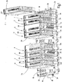
- the Fig. 1 shows a perspective view of devices 2, 4, 6, 8, 12 attached to a support rail 10 and lined up with one another. These are in each case electrical devices with at least partially different functionality.
- the devices 2, 4, 6, 8, 12 have a corresponding height and depth, but differ in part in their width.
- a device 4 of the second type has a corresponding width, but a terminal strip 14 is arranged on one side surface, to which, for example, electrical or optical lines can be connected.
- a device 6 of a third type has a width that is approximately 50% larger.
- a device 8 of the fourth type in turn has a clamping strip 14 on one side surface.
- the fifth type of device is a feed device 12, which has a connection strip 16 for connecting electrical power supply lines and a socket 18 for connecting a signal line bus.
- the devices 2, 4, 6, 8, 12 each have a first housing part 2A, 6A, 12A and a matching second housing part 2B, 6B, which can be connected to the associated first housing part 2A, 6A, 12A, in particular can be plugged onto the latter and can be locked with it.
- the second housing parts 2B can be combined with different first housing parts 2A, 12A.
- the second housing parts 2B can have a different width than the first housing part 12A and can nevertheless be joined together.
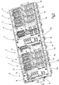
- the Fig. 2 shows a perspective view of the devices 2, 4, 6, 8, 12 of the FIGS Fig. 1 with the second housing parts 2B, 6B removed.
- a coupling module 20 for coupling energy supply lines between two devices 2, 4, 6, 8, 12 arranged adjacent to one another on the mounting rail 10 is fixed in the first housing parts 2A, 12A of the devices 2, 4, 12.
- a wider coupling module 70 for coupling power supply lines is defined in the first housing parts 6A of devices 6, 8, which are wider in comparison.
- the four-wire energy supply is transmitted from the terminal strip 16 via the coupling module 20 from the feed device 12 by means of a total of four separately pluggable and detachable energy connection elements 22 to the device 2 of the first type arranged adjacent to the mounting rail 10 and from there to the next in a corresponding manner adjacent devices 4 of the second type and the device 6 of the third type.
- Different through use Wide coupling modules 20, 70, uniformly designed energy connection elements 22 can be used for connecting devices 2, 4, 6, 8, 12 of different widths.
- each first housing part 2A of the devices 2, 4 has a coupling module 24 for coupling signal lines between two devices 2, 4, 6, 8, 12 arranged adjacent to one another on the mounting rail 10.
- the broader first housing parts 6A of the devices 6, 8 each have a wider coupling module 74 for coupling signal lines.
- the first housing part 12A of the feed devices 12 has a coupling module 76 which, compared to the coupling modules 24, 74, has a different number of contacts for the electrical unit accommodated in the feed device 12, in particular a higher number of contacts and preferably twice the number of contacts Use a double row arrangement.
- the signal lines are transmitted by means of a multi-pole, in the exemplary embodiment eleven-pole, signal connector element 26 to the device 2 of the first type and from there on to the device 4 of the second type and the device 6 of the third type.
- signal connector elements 26 can be used for connecting devices 2, 4, 6, 8, 12 of different widths.
- the signal lines are also coupled to the second feed device 12 and from there further to the devices 8, 2 connected to them.
- the second feed device 12 is re-fed using the terminal strip 16.
- the dimensions of the coupling modules 20, 24, 70, 74, 76 are each adapted to the size of the first housing part 2A, 6A, 12A, in particular are For first housing parts 2A, 6A, 12A of different widths, coupling modules 20, 24, 70, 74, 76 of correspondingly different widths are provided.
- the respective second housing part 2B, 6B with the electronic assembly located therein can be removed and exchanged without the energy or signal connection between the adjacent devices 2 , 4, 6, 8, 12 is interrupted.
- the signal and / or energy connection can also be maintained and the energy or signal connection can only be interrupted, if necessary only partially.
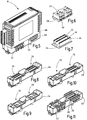
- the Fig. 3 shows a perspective view of the device 2 of the first type with the second housing part 2B removed from the first housing part 2A.
- the Fig. 4 shows a perspective view of the device 2 with the second housing part 2B placed on the first housing part 2A.
- no coupling modules 20, 24 have yet been inserted into the first housing part 2A.
- the two receiving devices 28 for receiving the coupling modules 20, 24 are visible.
- Each receiving device 28 comprises a total of four latching elements 30, which are formed in one piece by the first housing part 2A.
- the latching elements 30 are arranged on the two mutually opposite side walls 32 of the first housing part 2A, which extend transversely to the longitudinal axis of the mounting rail 10 or transversely to a longitudinal axis of one of the first housing part 2A, preferably a one-piece receptacle 34 for the mounting rail 10.
- the side walls 32 for the passage of the energy connection elements 22 or signal connection elements 26 are offset in a crenellated manner.
- cover elements 38 can preferably be inserted into a groove 36 made on the outside of the side walls 32, preferably detachably and / or without tools, in order to remove the between the crenellated shoulders of the first housing part 2A and the rectilinear housing edge of the second housing part 2B to cover existing openings.
- the cover elements 38 can be arranged in a row of devices 2, 4, 6, 8, 12 ( Fig. 1 ) be inserted on one side at the front ends of the end devices 2, 12, or on both sides in the case of a single device 2, as in FIG Fig. 4 shown. Cover elements 38 can also be used only partially on one side of the device 2, 4, 6, 8, 12, for example if no coupling is required at the corresponding location of the device 2, 4, 6, 8, 12, ie no energy or signal connection elements 22, 26 are used or no coupling module 20, 24, 70, 74 assigned to the opening is fixed in the first housing part 2A, 6A, 12A.
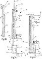
- the Figure 3A shows an enlarged view of a section of a partially sectioned side view of the second housing part 2B removed from the first housing part 2A.
- the second housing part 2B forms, in one piece, a latching means 78 which projects beyond the end of its housing shell 82 and can be deflected in a resilient manner and which has a latching flank 84 and a run-up flank 86 ( Figure 4A ) having.
- the latching flank 84 includes with the plug-on direction 88, in which the second housing part 2B can be plugged onto the first housing part 2A, a larger angle of between 50 and 70 ° in the exemplary embodiment than the ramp flank 86, which with the plug-on direction 88 forms an angle between 30 and Includes 50 °.
- FIG. 3B shows a perspective view of a blocking element 80 slidably mounted in the second housing part 2B
- Figure 4A shows in Enlarged representation of a section of a partially sectioned side view of the second housing part 2B placed on the first housing part 2A.
- the second housing part 2B has a latching means 78 and a blocking element 80 on its opposite narrow sides.
- the blocking element 80 is in the in the Figure 4A shown, introduced into the second housing part 2B in a form-fitting contact with a blocking means 89 formed in one piece by the second housing part 2B, which in addition to the inherent rigidity of the blocking element 80 reliably prevents the blocking element 80 and thus the latching means 78 from being deflected.
- the blocking means 89 is connected to the bottom and to a side wall 32 of the first housing part 2A, as a result of which it has high rigidity.
- the blocking means 89 extends over a length which is more than 50% of the height of the first housing part 2A.
- the blocking means 89 and / or the blocking element 80 have a run-on slope 85, 87, by means of which the insertion of the blocking element 80 is simplified and also a securing of the inserted state of the blocking element 80 can be achieved by a slightly jamming system.
- the blocking element 80 has an L-shaped cross-sectional shape in the exemplary embodiment, the wider first leg 94 in the region of the end facing the latching means 78 being in contact with guide means 91 which are preferably formed in one piece by the second housing part 2B, in particular the housing shell 82.
- the first leg 94 forms a driver means 93, which in the in the Figure 3A shown condition in contact with a stop means 95 which is preferably formed in one piece by the second housing part 2B.
- the blocking element 80 is on the one hand captively arranged on the second housing part 2B and, on the other hand, the second housing part 2B can thereby be pulled off the first housing part 2A by pulling on the blocking element 80 and then removed.
- the second leg 96 of the blocking element 80 extends at right angles to the first leg 94 and forms the contact surface 97 for the latching means 78 at one end.
- the blocking element 80 and in particular the second leg 96 form a handle 98 which serves to handle the blocking element 80 and also in the manner shown in FIG Figure 4A shown, the assembled state securing position of the blocking element 80 is accessible.
- the blocking element 80 has a tool engagement surface 99, in particular in the area of the handle 98, in the exemplary embodiment an opening or recess for inserting a flat-blade screwdriver. The blocking element 80 can be actuated without tools.
- the Fig. 5 shows a perspective view of the device 8 of the third type with a total of four inserted energy connection elements 22 and one inserted signal connection element 26.
- the Fig. 6 shows a perspective view of a coupling module 20 for coupling power supply lines, which is designed for an operating voltage of 230 V or more.
- the parts that may be live during operation are arranged so that they are safe to touch either directly through the coupling module 20 itself or in the installed state in cooperation with the first housing part 2A.
- the four-pole coupling element 20 in total has four connection points 40 at each of its opposite longitudinal edges, in particular plug contacts, for coupling the energy supply lines to a device arranged adjacent to the mounting rail 10 by means of an energy connection element 22 ( Fig. 5 ).
- connection point 40 between mutually opposite connection points 40, in particular in the middle, the coupling module 20 each has a further connection point 42, in particular a further plug contact, for the electrical components of the device 8 arranged in the housing, in particular in the second housing part 6B have other connection points off-center.
- the coupling module 20 can be constructed symmetrically to a central plane and can therefore be inserted into the first housing part 6A in different orientations.
- the Fig. 7 shows a perspective view of the coupling module 24 for coupling signal lines.
- the coupling module 24 points along it Long sides near the edge each have a multi-pole, in the exemplary embodiment eleven-pole terminal block 44 for coupling the signal lines to the neighboring devices.
- the coupling module 24, in the exemplary embodiment off-center, has a further connection strip 46 for the components of the device 8 arranged in the housing, in particular in the second housing part 6B.
- the Fig. 8 shows a perspective view of a first housing part 2A, a coupling module 24 for coupling signal lines being inserted in each of the two receiving devices 28.
- the Fig. 9 shows a perspective view of a first housing part 2A, a coupling module 20 for coupling energy supply lines being inserted in each of the two receiving devices 28.
- the Fig. 10 shows a perspective view of a first housing part 2A, into which a coupling module 24 for coupling signal lines and a coupling module 20 for coupling energy supply lines are inserted.
- the Fig. 11 shows a perspective view of the first housing part 2A of FIG Fig. 10 , wherein a total of four energy connection elements 22 are inserted into the coupling module 20 and a multipole signal connection element 26 is inserted into the coupling module 24 on each side.
- the multipole signal connection element 26 has a recess 48 which extends in the longitudinal direction, in particular a groove which is essentially U-shaped in cross-section and into which the second housing part 6B engages with its housing edge ( Fig. 5 ), thereby positively securing the connecting position of the signal connector element 26.
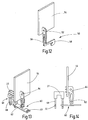
- the Fig. 12 shows a perspective view of the contacting of a protective conductor electrode 50 through a circuit board connection 52 of a circuit board 54 arranged in the device 8.
- the protective conductor electrode 50 with its free end facing the circuit board connection 52, preferably projects between two receptacles 28 for fixing the coupling modules 20, 24, 70 , 74 into the first housing part 2A, 6A, 12A.
- the hook-shaped section 58 With the hook-shaped section 58, the protective conductor electrode 50 protrudes from the first housing part 6A and, when the device 8 is placed on the mounting rail 10, comes into direct electrically conductive contact, for example clamping, cutting or resilient, with the mounting rail 10, which in turn is grounded.
- an earth connection or protective conductor connection of the circuit board 54 is guaranteed directly by placing the device 8 on the mounting rail 10.
- the Fig. 13 shows a perspective view of a contact element 60 of the coupling module 20 for the power supply lines.
- the Fig. 14 shows a side view of the arrangement of the Fig. 13 .
- the contact element 60 is a flat stamped / bent part, from the surface of which a contact lug 62 is bent for the board connection 64. At its opposite ends, the contact element 60 has a connection point 40, into each of which an energy connector element 22 can be inserted.
- the energy connector element 22 has a resiliently deformable, in particular fork-shaped contact member 66 with two spring contact legs 68 which can be inserted into the opening of the connection point 40.
- the contact legs 68 have a preferably rectangular shoulder 72 at a transition to a tapered free end section, which forms a stop when the energy connection element 22 is inserted into the connection point 40.
- the circuit board connection 52 for the protective conductor electrode 50 and the circuit board connection 64 for the contact element 60 of the coupling module 20 can be identical parts, both in terms of production technology and in terms of Assembly security and operational security is advantageous. Due to a different arrangement of the circuit board connections 52, 64 on the circuit board 54, in particular a different distance from the edge of the circuit board 54, and / or by a different length of the free end 56 on the one hand and the contact lug 62 on the other hand, even when using identical parts for the Board connections 52, 64 can be ensured which contact is leading; in particular, it can be ensured that when the board 54 is placed on, the connection between the board connection 52 and the protective conductor electrode 50 can be established first, and only then can the connection between the board connection 64 and the contact element 60 be established is.
Landscapes
- Engineering & Computer Science (AREA)
- Automation & Control Theory (AREA)
- Microelectronics & Electronic Packaging (AREA)
- Connector Housings Or Holding Contact Members (AREA)
Claims (14)
- Boîtier pour des appareils (2, 4, 6, 8, 12) pouvant être montés et rangés les uns à côté des autres sur un rail (10) porteur, notamment boîtier d'électronique à rangées, le boîtier ayant une premier partie (2A, 6A, 12A) de boîtier, au moyen de laquelle l'appareil (2, 4, 6, 8, 12) peut être monté sur le rail (10) porteur, la première partie (2A, 6A, 12A) du boîtier ayant au moins deux dispositifs (28) de réception pour la fixation de, respectivement, un module (20, 24, 70, 74) de connexion sur la première partie (2A, 6A, 12A) du boîtier et dans lequel, sur les au moins deux dispositifs (28) de réception, montés, de préférence à distance l'un de l'autre, dans la première partie (2A, 6A, 12A) du boîtier, soit peut être fixé un module (20, 70) de connexion pour la connexion de lignes d'alimentation en énergie entre deux appareils (2, 4, 6, 8, 12) montés au voisinage l'un de l'autre sur le rail porteur, soit peut être fixé à un module (24, 74) de connexion pour la connexion de lignes de signaux entre deux appareils (2, 4, 6, 8, 12) montés au voisinage l'un de l'autre sur le rail porteur, le boîtier ayant une deuxième partie (2b, 6b) de boîtier, la deuxième partie (2b, 6b) de boîtier pouvant être assemblée de manière amovible à la première partie (2A, 6A, 12A) du boîtier à l'aide d'un moyen (78) d'encliquetage pouvant être dévié élastiquement, caractérisé en ce que la déviation du moyen (78) d'encliquetage peut être bloquée par un élément (80) de blocage monté mobile sur la deuxième partie (2b, 6b) du boîtier et ainsi l'état, assemblé à la première partie (2A, 6A, 12A) du boîtier, de la deuxième partie (2b, 6b) du boîtier, peut être assuré et en ce que l'élément (80) de blocage est monté mobile dans la deuxième partie (2b) du boîtier.
- Boîtier suivant la revendication 1, caractérisé en ce que le module (20, 24, 70, 74) de connexion peut être fixé de manière détachable, notamment de manière détachable sans outil, à au moins l'un des dispositifs (28) de réception, de préférence à tous les dispositifs (28) de réception de la première partie (2A, 6A, 12A) du boîtier.
- Boîtier suivant la revendication 1 ou 2, caractérisé en ce que un, de préférence tous les dispositifs (28) de réception, a au moins un élément (30) d'encliquetage avec lequel le module (20, 24, 70, 74) de connexion peut être mis en prise lors de la fixation sur la première partie (2A, 6A, 12A) du boîtier et en ce qu'au moins une partie des éléments (30) d'encliquetage est constituée en partie intégrante des parois (32) latérales de la première partie (2A, 6A, 12A) du boîtier, qui s'étendent transversalement à l'axe longitudinal du rail (10) porteur ou s'étendent transversalement à un axe longitudinal d'un logement (34) pour le rail (10) porteur, constitué, de préférence, d'une seule pièce par la première partie (2A, 6A, 12A) du boîtier.
- Boîtier suivant l'une des revendications précédentes, caractérisé en ce que, dans au moins l'un des dispositifs (28) de réception, peut être fixé un module (20, 24, 70, 74) de connexion, auquel au moins une ligne de signaux, de préférence plusieurs lignes de signaux, peut être connectée entre deux appareils (2, 4, 6, 8, 12) montés au voisinage l'un de l'autre sur le rail (10) porteur.
- Boîtier suivant l'une des revendications précédentes, caractérisé en ce qu'au moins l'un des modules (20, 24, 70, 74) de connexion, fixés dans la première partie (2A, 6A, 12A) du boîtier, a, sur ou près de ses bords opposés l'un à l'autre, respectivement, des points (40, 44) de connexion, notamment des contacts mâles pour la connexion de lignes de signaux d'alimentation en énergie à un appareil (2, 4, 6, 8, 12) monté voisin sur le rail (10) porteur, au moyen d'éléments (22, 26) de liaison, de préférence enfichables, et en ce que, entre les points de connexion, qui sont associés aux appareils (2, 4, 6, 8, 12) montés voisins sur le rail porteur, le module (20, 24, 70, 74) de connexion a au moins un autre point de connexion, notamment au moins un autre contact mâle pour des composants, disposés dans le boîtier, de l'appareil (2, 4, 6, 8, 12).
- Système modulaire à boîtier pour des appareils (2, 4, 6, 8, 12) pouvant être montés et rangés les uns à côté des autres sur un rail (10) porteur, le système modulaire à boîtier, ayant un boîtier suivant l'une des revendications 1 à 5, ayant, dans au moins une dimension de construction, une première partie (2A, 6A, 12A) de boîtier, au moyen de laquelle l'appareil (2, 4, 6, 8, 12) peut être monté sur le rail (10) porteur,
dans lequel
le système modulaire à boîtier a à la fois au moins un module (20, 70) de connexion pour la connexion de lignes d'alimentation en énergie et aussi au moins un module (24, 74) de connexion pour la connexion de lignes de signaux, et dans lequel,
sur au moins deux dispositifs (28) de réception, montés de préférence à distance l'un de l'autre dans la première partie (2A, 6A, 12A) du boîtier, soit un module (20, 70) de connexion peut être fixé pour la connexion de lignes d'alimentation en énergie entre deux appareils (2, 4, 6, 8, 12) montés voisins l'un de l'autre sur le rail (10) porteur, soit un module (24, 74) de connexion peut être fixé pour la connexion de lignes de signaux entre deux appareils (2, 4, 6, 8, 12) montés au voisinage l'un de l'autre sur le rail (10) porteur. - Système modulaire à boîtier suivant la revendication 6, caractérisé en ce que le système modulaire à boîtier a, en outre, à la fois des éléments (22) connecteurs d'énergie, notamment des connecteurs électriques à enfichage pour la connexion de lignes d'alimentation en énergie et aussi des éléments (26) de connecteur de signaux, notamment des connecteurs électriques à enfichage pour la connexion de lignes de signaux.
- Système modulaire à boîtier suivant la revendication 7, caractérisé en ce que le au moins un élément (22) connecteur d'énergie et/ou un élément (26) connecteur de signaux est multipolaire, de manière à pouvoir ainsi connecter plusieurs, et de préférence toutes les lignes d'alimentation en énergie et/ou les lignes de signaux à connecter entre deux appareils (2, 4, 6, 8, 12) montés au voisinage l'un de l'autre sur le rail (10) porteur.
- Système modulaire à boîtier suivant la revendication 8, caractérisé en ce que l'élément (22) connecteur d'énergie et/ou l'élément (26) de connecteur de signaux multipolaire a, dans une partie enjambant les points de connexion aux éléments de connexion des appareils (2, 4, 6, 8, 12) voisins, un évidement (48), dans lequel la première partie (2A, 6A, 12A) du boîtier ou la deuxième partie (2B, 6B) du boîtier pouvant être reliée à la première partie (2A, 6A, 12A) du boîtier pénètre et ainsi fixe à complémentarité de forme la position de connexion de l'élément (22) de connecteur d'énergie et/ou de l'élément (26) de connecteur de signaux, notamment une position enfichée d'un connecteur multipolaire à enfichage.
- Système modulaire à boîtier suivant l'une des revendications 6 à 9, caractérisé en ce qu'au moins une partie des modules (20, 24, 70, 74) de connexion des lignes d'alimentation en énergie a une rigidité diélectrique d'au moins 230 V, notamment d'au moins 380 V et de préférence d'au moins 500 V et/ou une aptitude à porter le courant d'au moins 5 A, notamment d'au moins 10 A et de préférence d'au moins 16 A.
- Système modulaire à boîtier suivant l'une des revendications 7 à 10, caractérisé en ce que le au moins un connecteur électrique à enfichage a, pour l'enfichage dans un module (20, 24, 70, 74) de connexion, un organe (66) de contact, notamment en forme de fourche, déformable élastiquement, qui peut être enfiché dans une ouverture de l'élément (60) de contact du module (20, 70) de connexion.
- Système modulaire à boîtier suivant l'une des revendications 6 à 11, caractérisé en ce que le système modulaire à boîtier a, en outre, une partie (12) de boîtier d'entrée, qui a des dispositifs (16) d'entrée de lignes d'alimentation en énergie et/ou des dispositifs (18) d'entrée de lignes de signaux et, en outre, au moins un module (20, 70) de connexion pour la connexion de lignes d'alimentation en énergie et/ou au moins un module (24, 74) de connexion pour la connexion de lignes de signaux à un appareil (2, 4, 6, 8, 12) monté au voisinage sur le rail (10) porteur.
- Appareil (2, 4, 6, 8, 12) ayant un boîtier pouvant être monté sur un rail (10) porteur suivant l'une des revendications 1 à 5, dans lequel, sur les au moins deux dispositifs (28) de réception, montés de préférence à distance les uns des autres dans la première partie (2A, 6A, 12A) du boîtier, soit est fixé un module (20, 70) de connexion pour la connexion de lignes d'alimentation en énergie entre deux appareils (2, 4, 6, 8, 12) montés au voisinage les uns des autres sur le rail (10) porteur, soit est fixé un module (24, 74) de connexion pour le couplage de lignes de signaux entre deux appareils (2, 4, 6, 8, 12), montés au voisinage l'un de l'autre sur le rail (10) porteur et dans lequel deux modules (20, 24, 70, 74) de connexion, fixés au voisinage l'un de l'autre dans la première partie (2A, 6A, 12A) du boîtier, sont à distance l'un de l'autre.
- Appareil (2, 4, 6, 8, 12) suivant la revendication 13, caractérisé en ce que, dans au moins l'un des dispositifs (28) de réception, est fixé un module (20, 24, 70, 74) de connexion, avec lequel peut être connectée au moins une ligne de signaux, notamment une ligne de signaux électriques et de préférence plusieurs lignes de signaux électriques, entre deux appareils (2, 4, 6, 8, 12), montés au voisinage l'un de l'autre sur le rail (10) porteur.
Applications Claiming Priority (2)
| Application Number | Priority Date | Filing Date | Title |
|---|---|---|---|
| DE102012021055.8A DE102012021055A1 (de) | 2012-10-25 | 2012-10-25 | Gehäuse für an einer Tragschiene anbringbare und aneinander anreihbare Vorrichtungen, zugehöriges Gehäuse-Baukastensystem und Vorrichtung mit einem solchen Gehäuse |
| PCT/EP2013/003205 WO2014063821A1 (fr) | 2012-10-25 | 2013-10-24 | Boîtier pour des dispositifs pouvant être appliqués et rangés les uns contre les autres sur un rail de support, système modulaire de boîtier associé et dispositif comprenant un tel boîtier |
Publications (2)
| Publication Number | Publication Date |
|---|---|
| EP2912931A1 EP2912931A1 (fr) | 2015-09-02 |
| EP2912931B1 true EP2912931B1 (fr) | 2020-04-29 |
Family
ID=49488549
Family Applications (1)
| Application Number | Title | Priority Date | Filing Date |
|---|---|---|---|
| EP13783258.0A Active EP2912931B1 (fr) | 2012-10-25 | 2013-10-24 | Boîtier pour appareils montés côte à côte sur un rail ainsi que système modulaire associé et appareils avec un tel boîtier. |
Country Status (3)
| Country | Link |
|---|---|
| EP (1) | EP2912931B1 (fr) |
| DE (1) | DE102012021055A1 (fr) |
| WO (1) | WO2014063821A1 (fr) |
Cited By (1)
| Publication number | Priority date | Publication date | Assignee | Title |
|---|---|---|---|---|
| WO2025031713A1 (fr) | 2023-08-08 | 2025-02-13 | Friedrich Lütze GmbH | Dispositif de connexion |
Families Citing this family (8)
| Publication number | Priority date | Publication date | Assignee | Title |
|---|---|---|---|---|
| DE102015213744A1 (de) * | 2015-07-21 | 2017-01-26 | Ellenberger & Poensgen Gmbh | Stromverteiler |
| EP3209101B1 (fr) * | 2016-02-18 | 2020-04-08 | Schneider Electric Industries SAS | Module pour un contrôleur logique |
| DE102018126949A1 (de) * | 2018-10-29 | 2020-04-30 | Innogy Se | Ladevorrichtung für elektrofahrzeuge |
| DE102018133647A1 (de) | 2018-12-28 | 2020-07-02 | Beckhoff Automation Gmbh | Schaltschranksystem aus Basismodul und Funktionsmodulen sowie Funktionsmodul |
| DE102018133657A1 (de) | 2018-12-28 | 2020-07-02 | Beckhoff Automation Gmbh | Basismodul und funktionsmodul für ein schaltschranksystem und schaltschranksystem |
| DE102018133646A1 (de) | 2018-12-28 | 2020-07-02 | Beckhoff Automation Gmbh | Basismodul und Funktionsmodul für ein Schaltschranksystem |
| DE102019106082B4 (de) | 2019-03-11 | 2021-06-24 | Beckhoff Automation Gmbh | Schaltschranksystem mit dichtungseinsatz |
| CN117937111B (zh) * | 2024-02-19 | 2024-09-17 | 人天通信集团有限公司 | 一种一体化基站天线 |
Citations (5)
| Publication number | Priority date | Publication date | Assignee | Title |
|---|---|---|---|---|
| DE3600590A1 (de) * | 1986-01-11 | 1987-07-16 | Jaeger Lecoultre Sa | Gliederband |
| DE19748429A1 (de) * | 1997-11-03 | 1999-05-06 | Siemens Ag | Kommunikationsfähige Schaltgeräteeinheit |
| DE69415164T2 (de) * | 1994-10-10 | 1999-10-28 | Molex Inc., Lisle | Elektrischer Verbinder mit Lagesicherungssystem. |
| US20070155221A1 (en) * | 2005-07-05 | 2007-07-05 | I F M Electronic Gmbh | Housing for connection to an electrical line |
| WO2009060548A1 (fr) * | 2007-11-09 | 2009-05-14 | Idec Corporation | Structure de couplage de dispositif électrique |
Family Cites Families (4)
| Publication number | Priority date | Publication date | Assignee | Title |
|---|---|---|---|---|
| EP0661915A1 (fr) * | 1993-12-28 | 1995-07-05 | RKC Instruments Inc. | Dispositif de commande modulaire |
| DE19748531A1 (de) * | 1997-11-03 | 1999-05-06 | Siemens Ag | Aufbausystem für Verbraucherabzweige mit stehender Verdrahtung |
| DE20108460U1 (de) | 2001-05-19 | 2001-10-25 | Wieland Electric GmbH, 96052 Bamberg | Modulares Bausatzsystem für eine streckbare elektrische Anschlussvorrichtung und elektrische Anschlussvorrichtung |
| DE202010004408U1 (de) * | 2009-12-10 | 2011-04-21 | Weidmüller Interface GmbH & Co. KG | Reihung von Anschlussmodulen |
-
2012
- 2012-10-25 DE DE102012021055.8A patent/DE102012021055A1/de not_active Ceased
-
2013
- 2013-10-24 EP EP13783258.0A patent/EP2912931B1/fr active Active
- 2013-10-24 WO PCT/EP2013/003205 patent/WO2014063821A1/fr not_active Ceased
Patent Citations (5)
| Publication number | Priority date | Publication date | Assignee | Title |
|---|---|---|---|---|
| DE3600590A1 (de) * | 1986-01-11 | 1987-07-16 | Jaeger Lecoultre Sa | Gliederband |
| DE69415164T2 (de) * | 1994-10-10 | 1999-10-28 | Molex Inc., Lisle | Elektrischer Verbinder mit Lagesicherungssystem. |
| DE19748429A1 (de) * | 1997-11-03 | 1999-05-06 | Siemens Ag | Kommunikationsfähige Schaltgeräteeinheit |
| US20070155221A1 (en) * | 2005-07-05 | 2007-07-05 | I F M Electronic Gmbh | Housing for connection to an electrical line |
| WO2009060548A1 (fr) * | 2007-11-09 | 2009-05-14 | Idec Corporation | Structure de couplage de dispositif électrique |
Cited By (2)
| Publication number | Priority date | Publication date | Assignee | Title |
|---|---|---|---|---|
| WO2025031713A1 (fr) | 2023-08-08 | 2025-02-13 | Friedrich Lütze GmbH | Dispositif de connexion |
| DE102023003274A1 (de) | 2023-08-08 | 2025-02-13 | Friedrich Lütze GmbH | Verbindungsvorrichtung |
Also Published As
| Publication number | Publication date |
|---|---|
| EP2912931A1 (fr) | 2015-09-02 |
| WO2014063821A1 (fr) | 2014-05-01 |
| DE102012021055A1 (de) | 2014-04-30 |
Similar Documents
| Publication | Publication Date | Title |
|---|---|---|
| EP2912931B1 (fr) | Boîtier pour appareils montés côte à côte sur un rail ainsi que système modulaire associé et appareils avec un tel boîtier. | |
| EP2255410B1 (fr) | Barrette a bornes ou bloc de barrettes a bornes | |
| EP1189307B1 (fr) | Barette à bornes électrique | |
| EP1811604B1 (fr) | Barette à bornes électriques | |
| EP2839544B1 (fr) | Bornier de test | |
| DE10301003B3 (de) | Modulares Installationsgerät | |
| EP0709933A2 (fr) | Installation de réglage avec bus | |
| EP3246995A1 (fr) | Systeme de barres omnibus | |
| EP3066901B1 (fr) | Système d'assemblage de composants | |
| DE102013112115A1 (de) | Brückenmodul für ein Komponentenaufbausystem | |
| EP2810342B1 (fr) | Élément de couplage électrique | |
| EP2878183B1 (fr) | Système de bus de terrain modulaire, module support et module bus de terrain | |
| EP2497173B1 (fr) | Dispositif de réception de composants électriques | |
| EP2497169A2 (fr) | Agencement de montage pour appareils électriques | |
| EP2429037B1 (fr) | Elément de serrage de cadre pour commutateurs électromécaniques doté d'une pièce de raccordement intégrée | |
| EP3076504B1 (fr) | Dispositif adaptateur pour un système de barre omnibus | |
| DE10005219C2 (de) | Isoliergehäuse zur Befestigung an einer Tragschiene | |
| DE102012203554A1 (de) | Sammelschienenabgreifklemme | |
| EP3142196A1 (fr) | Adaptateur de raccordement d'un systeme d'alimentation de barrettes de connexion | |
| DE102005023452B4 (de) | Montage- und Verdrahtungssystem für elektrische Funktionsmodule, insbesondere für Schaltgeräte | |
| DE102009045121B4 (de) | System zur Verteilung von elektrischer Energie und Verfahren zur Anbringung eines Adapters an einer Sammelschiene | |
| DE4111956A1 (de) | Mehrpolige elektrische anschlussvorrichtung | |
| EP4106119B1 (fr) | Barre conductrice d'un système d'éclairage pourvu de porte-câble et de cage à fils | |
| EP3876355B1 (fr) | Dispositif de connexion et module électromécanique | |
| DE10307352B4 (de) | Elektrifiziersystem |
Legal Events
| Date | Code | Title | Description |
|---|---|---|---|
| PUAI | Public reference made under article 153(3) epc to a published international application that has entered the european phase |
Free format text: ORIGINAL CODE: 0009012 |
|
| 17P | Request for examination filed |
Effective date: 20150317 |
|
| AK | Designated contracting states |
Kind code of ref document: A1 Designated state(s): AL AT BE BG CH CY CZ DE DK EE ES FI FR GB GR HR HU IE IS IT LI LT LU LV MC MK MT NL NO PL PT RO RS SE SI SK SM TR |
|
| AX | Request for extension of the european patent |
Extension state: BA ME |
|
| DAX | Request for extension of the european patent (deleted) | ||
| 17Q | First examination report despatched |
Effective date: 20160913 |
|
| STAA | Information on the status of an ep patent application or granted ep patent |
Free format text: STATUS: EXAMINATION IS IN PROGRESS |
|
| GRAP | Despatch of communication of intention to grant a patent |
Free format text: ORIGINAL CODE: EPIDOSNIGR1 |
|
| STAA | Information on the status of an ep patent application or granted ep patent |
Free format text: STATUS: GRANT OF PATENT IS INTENDED |
|
| RIC1 | Information provided on ipc code assigned before grant |
Ipc: H01R 9/26 20060101ALI20191023BHEP Ipc: H01R 13/639 20060101ALI20191023BHEP Ipc: H02B 1/056 20060101ALI20191023BHEP Ipc: H05K 7/14 20060101AFI20191023BHEP |
|
| INTG | Intention to grant announced |
Effective date: 20191114 |
|
| GRAS | Grant fee paid |
Free format text: ORIGINAL CODE: EPIDOSNIGR3 |
|
| GRAA | (expected) grant |
Free format text: ORIGINAL CODE: 0009210 |
|
| STAA | Information on the status of an ep patent application or granted ep patent |
Free format text: STATUS: THE PATENT HAS BEEN GRANTED |
|
| AK | Designated contracting states |
Kind code of ref document: B1 Designated state(s): AL AT BE BG CH CY CZ DE DK EE ES FI FR GB GR HR HU IE IS IT LI LT LU LV MC MK MT NL NO PL PT RO RS SE SI SK SM TR |
|
| REG | Reference to a national code |
Ref country code: GB Ref legal event code: FG4D Free format text: NOT ENGLISH |
|
| REG | Reference to a national code |
Ref country code: CH Ref legal event code: EP |
|
| REG | Reference to a national code |
Ref country code: AT Ref legal event code: REF Ref document number: 1265302 Country of ref document: AT Kind code of ref document: T Effective date: 20200515 |
|
| REG | Reference to a national code |
Ref country code: DE Ref legal event code: R096 Ref document number: 502013014665 Country of ref document: DE |
|
| REG | Reference to a national code |
Ref country code: IE Ref legal event code: FG4D Free format text: LANGUAGE OF EP DOCUMENT: GERMAN |
|
| REG | Reference to a national code |
Ref country code: NL Ref legal event code: MP Effective date: 20200429 |
|
| REG | Reference to a national code |
Ref country code: LT Ref legal event code: MG4D |
|
| PG25 | Lapsed in a contracting state [announced via postgrant information from national office to epo] |
Ref country code: GR Free format text: LAPSE BECAUSE OF FAILURE TO SUBMIT A TRANSLATION OF THE DESCRIPTION OR TO PAY THE FEE WITHIN THE PRESCRIBED TIME-LIMIT Effective date: 20200730 Ref country code: SE Free format text: LAPSE BECAUSE OF FAILURE TO SUBMIT A TRANSLATION OF THE DESCRIPTION OR TO PAY THE FEE WITHIN THE PRESCRIBED TIME-LIMIT Effective date: 20200429 Ref country code: LT Free format text: LAPSE BECAUSE OF FAILURE TO SUBMIT A TRANSLATION OF THE DESCRIPTION OR TO PAY THE FEE WITHIN THE PRESCRIBED TIME-LIMIT Effective date: 20200429 Ref country code: PT Free format text: LAPSE BECAUSE OF FAILURE TO SUBMIT A TRANSLATION OF THE DESCRIPTION OR TO PAY THE FEE WITHIN THE PRESCRIBED TIME-LIMIT Effective date: 20200831 Ref country code: IS Free format text: LAPSE BECAUSE OF FAILURE TO SUBMIT A TRANSLATION OF THE DESCRIPTION OR TO PAY THE FEE WITHIN THE PRESCRIBED TIME-LIMIT Effective date: 20200829 Ref country code: NO Free format text: LAPSE BECAUSE OF FAILURE TO SUBMIT A TRANSLATION OF THE DESCRIPTION OR TO PAY THE FEE WITHIN THE PRESCRIBED TIME-LIMIT Effective date: 20200729 Ref country code: FI Free format text: LAPSE BECAUSE OF FAILURE TO SUBMIT A TRANSLATION OF THE DESCRIPTION OR TO PAY THE FEE WITHIN THE PRESCRIBED TIME-LIMIT Effective date: 20200429 |
|
| PG25 | Lapsed in a contracting state [announced via postgrant information from national office to epo] |
Ref country code: BG Free format text: LAPSE BECAUSE OF FAILURE TO SUBMIT A TRANSLATION OF THE DESCRIPTION OR TO PAY THE FEE WITHIN THE PRESCRIBED TIME-LIMIT Effective date: 20200729 Ref country code: RS Free format text: LAPSE BECAUSE OF FAILURE TO SUBMIT A TRANSLATION OF THE DESCRIPTION OR TO PAY THE FEE WITHIN THE PRESCRIBED TIME-LIMIT Effective date: 20200429 Ref country code: HR Free format text: LAPSE BECAUSE OF FAILURE TO SUBMIT A TRANSLATION OF THE DESCRIPTION OR TO PAY THE FEE WITHIN THE PRESCRIBED TIME-LIMIT Effective date: 20200429 Ref country code: LV Free format text: LAPSE BECAUSE OF FAILURE TO SUBMIT A TRANSLATION OF THE DESCRIPTION OR TO PAY THE FEE WITHIN THE PRESCRIBED TIME-LIMIT Effective date: 20200429 |
|
| PG25 | Lapsed in a contracting state [announced via postgrant information from national office to epo] |
Ref country code: AL Free format text: LAPSE BECAUSE OF FAILURE TO SUBMIT A TRANSLATION OF THE DESCRIPTION OR TO PAY THE FEE WITHIN THE PRESCRIBED TIME-LIMIT Effective date: 20200429 Ref country code: NL Free format text: LAPSE BECAUSE OF FAILURE TO SUBMIT A TRANSLATION OF THE DESCRIPTION OR TO PAY THE FEE WITHIN THE PRESCRIBED TIME-LIMIT Effective date: 20200429 |
|
| PG25 | Lapsed in a contracting state [announced via postgrant information from national office to epo] |
Ref country code: EE Free format text: LAPSE BECAUSE OF FAILURE TO SUBMIT A TRANSLATION OF THE DESCRIPTION OR TO PAY THE FEE WITHIN THE PRESCRIBED TIME-LIMIT Effective date: 20200429 Ref country code: SM Free format text: LAPSE BECAUSE OF FAILURE TO SUBMIT A TRANSLATION OF THE DESCRIPTION OR TO PAY THE FEE WITHIN THE PRESCRIBED TIME-LIMIT Effective date: 20200429 Ref country code: IT Free format text: LAPSE BECAUSE OF FAILURE TO SUBMIT A TRANSLATION OF THE DESCRIPTION OR TO PAY THE FEE WITHIN THE PRESCRIBED TIME-LIMIT Effective date: 20200429 Ref country code: DK Free format text: LAPSE BECAUSE OF FAILURE TO SUBMIT A TRANSLATION OF THE DESCRIPTION OR TO PAY THE FEE WITHIN THE PRESCRIBED TIME-LIMIT Effective date: 20200429 Ref country code: CZ Free format text: LAPSE BECAUSE OF FAILURE TO SUBMIT A TRANSLATION OF THE DESCRIPTION OR TO PAY THE FEE WITHIN THE PRESCRIBED TIME-LIMIT Effective date: 20200429 Ref country code: RO Free format text: LAPSE BECAUSE OF FAILURE TO SUBMIT A TRANSLATION OF THE DESCRIPTION OR TO PAY THE FEE WITHIN THE PRESCRIBED TIME-LIMIT Effective date: 20200429 Ref country code: ES Free format text: LAPSE BECAUSE OF FAILURE TO SUBMIT A TRANSLATION OF THE DESCRIPTION OR TO PAY THE FEE WITHIN THE PRESCRIBED TIME-LIMIT Effective date: 20200429 |
|
| REG | Reference to a national code |
Ref country code: DE Ref legal event code: R097 Ref document number: 502013014665 Country of ref document: DE |
|
| PG25 | Lapsed in a contracting state [announced via postgrant information from national office to epo] |
Ref country code: SK Free format text: LAPSE BECAUSE OF FAILURE TO SUBMIT A TRANSLATION OF THE DESCRIPTION OR TO PAY THE FEE WITHIN THE PRESCRIBED TIME-LIMIT Effective date: 20200429 Ref country code: PL Free format text: LAPSE BECAUSE OF FAILURE TO SUBMIT A TRANSLATION OF THE DESCRIPTION OR TO PAY THE FEE WITHIN THE PRESCRIBED TIME-LIMIT Effective date: 20200429 |
|
| PLBE | No opposition filed within time limit |
Free format text: ORIGINAL CODE: 0009261 |
|
| STAA | Information on the status of an ep patent application or granted ep patent |
Free format text: STATUS: NO OPPOSITION FILED WITHIN TIME LIMIT |
|
| 26N | No opposition filed |
Effective date: 20210201 |
|
| REG | Reference to a national code |
Ref country code: DE Ref legal event code: R119 Ref document number: 502013014665 Country of ref document: DE |
|
| PG25 | Lapsed in a contracting state [announced via postgrant information from national office to epo] |
Ref country code: SI Free format text: LAPSE BECAUSE OF FAILURE TO SUBMIT A TRANSLATION OF THE DESCRIPTION OR TO PAY THE FEE WITHIN THE PRESCRIBED TIME-LIMIT Effective date: 20200429 |
|
| REG | Reference to a national code |
Ref country code: CH Ref legal event code: PL |
|
| GBPC | Gb: european patent ceased through non-payment of renewal fee |
Effective date: 20201024 |
|
| PG25 | Lapsed in a contracting state [announced via postgrant information from national office to epo] |
Ref country code: MC Free format text: LAPSE BECAUSE OF FAILURE TO SUBMIT A TRANSLATION OF THE DESCRIPTION OR TO PAY THE FEE WITHIN THE PRESCRIBED TIME-LIMIT Effective date: 20200429 Ref country code: LU Free format text: LAPSE BECAUSE OF NON-PAYMENT OF DUE FEES Effective date: 20201024 |
|
| REG | Reference to a national code |
Ref country code: BE Ref legal event code: MM Effective date: 20201031 |
|
| PG25 | Lapsed in a contracting state [announced via postgrant information from national office to epo] |
Ref country code: DE Free format text: LAPSE BECAUSE OF NON-PAYMENT OF DUE FEES Effective date: 20210501 Ref country code: FR Free format text: LAPSE BECAUSE OF NON-PAYMENT OF DUE FEES Effective date: 20201031 |
|
| PG25 | Lapsed in a contracting state [announced via postgrant information from national office to epo] |
Ref country code: CH Free format text: LAPSE BECAUSE OF NON-PAYMENT OF DUE FEES Effective date: 20201031 Ref country code: BE Free format text: LAPSE BECAUSE OF NON-PAYMENT OF DUE FEES Effective date: 20201031 Ref country code: GB Free format text: LAPSE BECAUSE OF NON-PAYMENT OF DUE FEES Effective date: 20201024 Ref country code: LI Free format text: LAPSE BECAUSE OF NON-PAYMENT OF DUE FEES Effective date: 20201031 |
|
| PG25 | Lapsed in a contracting state [announced via postgrant information from national office to epo] |
Ref country code: IE Free format text: LAPSE BECAUSE OF NON-PAYMENT OF DUE FEES Effective date: 20201024 |
|
| REG | Reference to a national code |
Ref country code: AT Ref legal event code: MM01 Ref document number: 1265302 Country of ref document: AT Kind code of ref document: T Effective date: 20201024 |
|
| PG25 | Lapsed in a contracting state [announced via postgrant information from national office to epo] |
Ref country code: AT Free format text: LAPSE BECAUSE OF NON-PAYMENT OF DUE FEES Effective date: 20201024 |
|
| PG25 | Lapsed in a contracting state [announced via postgrant information from national office to epo] |
Ref country code: TR Free format text: LAPSE BECAUSE OF FAILURE TO SUBMIT A TRANSLATION OF THE DESCRIPTION OR TO PAY THE FEE WITHIN THE PRESCRIBED TIME-LIMIT Effective date: 20200429 Ref country code: MT Free format text: LAPSE BECAUSE OF FAILURE TO SUBMIT A TRANSLATION OF THE DESCRIPTION OR TO PAY THE FEE WITHIN THE PRESCRIBED TIME-LIMIT Effective date: 20200429 Ref country code: CY Free format text: LAPSE BECAUSE OF FAILURE TO SUBMIT A TRANSLATION OF THE DESCRIPTION OR TO PAY THE FEE WITHIN THE PRESCRIBED TIME-LIMIT Effective date: 20200429 |
|
| PG25 | Lapsed in a contracting state [announced via postgrant information from national office to epo] |
Ref country code: MK Free format text: LAPSE BECAUSE OF FAILURE TO SUBMIT A TRANSLATION OF THE DESCRIPTION OR TO PAY THE FEE WITHIN THE PRESCRIBED TIME-LIMIT Effective date: 20200429 |