EP3246995A1 - Systeme de barres omnibus - Google Patents
Systeme de barres omnibus Download PDFInfo
- Publication number
- EP3246995A1 EP3246995A1 EP16169977.2A EP16169977A EP3246995A1 EP 3246995 A1 EP3246995 A1 EP 3246995A1 EP 16169977 A EP16169977 A EP 16169977A EP 3246995 A1 EP3246995 A1 EP 3246995A1
- Authority
- EP
- European Patent Office
- Prior art keywords
- busbar
- module
- busbar system
- protected
- base plate
- Prior art date
- Legal status (The legal status is an assumption and is not a legal conclusion. Google has not performed a legal analysis and makes no representation as to the accuracy of the status listed.)
- Granted
Links
Images







Classifications
-
- H—ELECTRICITY
- H01—ELECTRIC ELEMENTS
- H01R—ELECTRICALLY-CONDUCTIVE CONNECTIONS; STRUCTURAL ASSOCIATIONS OF A PLURALITY OF MUTUALLY-INSULATED ELECTRICAL CONNECTING ELEMENTS; COUPLING DEVICES; CURRENT COLLECTORS
- H01R13/00—Details of coupling devices of the kinds covered by groups H01R12/70 or H01R24/00 - H01R33/00
- H01R13/40—Securing contact members in or to a base or case; Insulating of contact members
-
- H—ELECTRICITY
- H01—ELECTRIC ELEMENTS
- H01R—ELECTRICALLY-CONDUCTIVE CONNECTIONS; STRUCTURAL ASSOCIATIONS OF A PLURALITY OF MUTUALLY-INSULATED ELECTRICAL CONNECTING ELEMENTS; COUPLING DEVICES; CURRENT COLLECTORS
- H01R13/00—Details of coupling devices of the kinds covered by groups H01R12/70 or H01R24/00 - H01R33/00
- H01R13/44—Means for preventing access to live contacts
- H01R13/447—Shutter or cover plate
-
- H—ELECTRICITY
- H01—ELECTRIC ELEMENTS
- H01R—ELECTRICALLY-CONDUCTIVE CONNECTIONS; STRUCTURAL ASSOCIATIONS OF A PLURALITY OF MUTUALLY-INSULATED ELECTRICAL CONNECTING ELEMENTS; COUPLING DEVICES; CURRENT COLLECTORS
- H01R13/00—Details of coupling devices of the kinds covered by groups H01R12/70 or H01R24/00 - H01R33/00
- H01R13/46—Bases; Cases
- H01R13/502—Bases; Cases composed of different pieces
-
- H—ELECTRICITY
- H01—ELECTRIC ELEMENTS
- H01R—ELECTRICALLY-CONDUCTIVE CONNECTIONS; STRUCTURAL ASSOCIATIONS OF A PLURALITY OF MUTUALLY-INSULATED ELECTRICAL CONNECTING ELEMENTS; COUPLING DEVICES; CURRENT COLLECTORS
- H01R13/00—Details of coupling devices of the kinds covered by groups H01R12/70 or H01R24/00 - H01R33/00
- H01R13/46—Bases; Cases
- H01R13/502—Bases; Cases composed of different pieces
- H01R13/506—Bases; Cases composed of different pieces assembled by snap action of the parts
-
- H—ELECTRICITY
- H01—ELECTRIC ELEMENTS
- H01R—ELECTRICALLY-CONDUCTIVE CONNECTIONS; STRUCTURAL ASSOCIATIONS OF A PLURALITY OF MUTUALLY-INSULATED ELECTRICAL CONNECTING ELEMENTS; COUPLING DEVICES; CURRENT COLLECTORS
- H01R25/00—Coupling parts adapted for simultaneous co-operation with two or more identical counterparts, e.g. for distributing energy to two or more circuits
- H01R25/16—Rails or bus-bars provided with a plurality of discrete connecting locations for counterparts
- H01R25/161—Details
- H01R25/162—Electrical connections between or with rails or bus-bars
-
- H—ELECTRICITY
- H01—ELECTRIC ELEMENTS
- H01R—ELECTRICALLY-CONDUCTIVE CONNECTIONS; STRUCTURAL ASSOCIATIONS OF A PLURALITY OF MUTUALLY-INSULATED ELECTRICAL CONNECTING ELEMENTS; COUPLING DEVICES; CURRENT COLLECTORS
- H01R9/00—Structural associations of a plurality of mutually-insulated electrical connecting elements, e.g. terminal strips or terminal blocks; Terminals or binding posts mounted upon a base or in a case; Bases therefor
- H01R9/22—Bases, e.g. strip, block, panel
- H01R9/24—Terminal blocks
- H01R9/2458—Electrical interconnections between terminal blocks
-
- H—ELECTRICITY
- H01—ELECTRIC ELEMENTS
- H01R—ELECTRICALLY-CONDUCTIVE CONNECTIONS; STRUCTURAL ASSOCIATIONS OF A PLURALITY OF MUTUALLY-INSULATED ELECTRICAL CONNECTING ELEMENTS; COUPLING DEVICES; CURRENT COLLECTORS
- H01R9/00—Structural associations of a plurality of mutually-insulated electrical connecting elements, e.g. terminal strips or terminal blocks; Terminals or binding posts mounted upon a base or in a case; Bases therefor
- H01R9/22—Bases, e.g. strip, block, panel
- H01R9/28—Terminal boards
-
- H—ELECTRICITY
- H02—GENERATION; CONVERSION OR DISTRIBUTION OF ELECTRIC POWER
- H02B—BOARDS, SUBSTATIONS OR SWITCHING ARRANGEMENTS FOR THE SUPPLY OR DISTRIBUTION OF ELECTRIC POWER
- H02B1/00—Frameworks, boards, panels, desks, casings; Details of substations or switching arrangements
- H02B1/015—Boards, panels, desks; Parts thereof or accessories therefor
- H02B1/04—Mounting thereon of switches or of other devices in general, the switch or device having, or being without, casing
- H02B1/044—Mounting through openings
-
- H—ELECTRICITY
- H02—GENERATION; CONVERSION OR DISTRIBUTION OF ELECTRIC POWER
- H02B—BOARDS, SUBSTATIONS OR SWITCHING ARRANGEMENTS FOR THE SUPPLY OR DISTRIBUTION OF ELECTRIC POWER
- H02B1/00—Frameworks, boards, panels, desks, casings; Details of substations or switching arrangements
- H02B1/015—Boards, panels, desks; Parts thereof or accessories therefor
- H02B1/04—Mounting thereon of switches or of other devices in general, the switch or device having, or being without, casing
- H02B1/052—Mounting on rails
-
- H—ELECTRICITY
- H02—GENERATION; CONVERSION OR DISTRIBUTION OF ELECTRIC POWER
- H02B—BOARDS, SUBSTATIONS OR SWITCHING ARRANGEMENTS FOR THE SUPPLY OR DISTRIBUTION OF ELECTRIC POWER
- H02B1/00—Frameworks, boards, panels, desks, casings; Details of substations or switching arrangements
- H02B1/015—Boards, panels, desks; Parts thereof or accessories therefor
- H02B1/04—Mounting thereon of switches or of other devices in general, the switch or device having, or being without, casing
- H02B1/052—Mounting on rails
- H02B1/0523—Mounting on rails locked into position by a sliding member
-
- H—ELECTRICITY
- H02—GENERATION; CONVERSION OR DISTRIBUTION OF ELECTRIC POWER
- H02B—BOARDS, SUBSTATIONS OR SWITCHING ARRANGEMENTS FOR THE SUPPLY OR DISTRIBUTION OF ELECTRIC POWER
- H02B1/00—Frameworks, boards, panels, desks, casings; Details of substations or switching arrangements
- H02B1/015—Boards, panels, desks; Parts thereof or accessories therefor
- H02B1/04—Mounting thereon of switches or of other devices in general, the switch or device having, or being without, casing
- H02B1/056—Mounting on plugboards
-
- H—ELECTRICITY
- H02—GENERATION; CONVERSION OR DISTRIBUTION OF ELECTRIC POWER
- H02B—BOARDS, SUBSTATIONS OR SWITCHING ARRANGEMENTS FOR THE SUPPLY OR DISTRIBUTION OF ELECTRIC POWER
- H02B1/00—Frameworks, boards, panels, desks, casings; Details of substations or switching arrangements
- H02B1/14—Shutters or guards for preventing access to contacts
-
- H—ELECTRICITY
- H02—GENERATION; CONVERSION OR DISTRIBUTION OF ELECTRIC POWER
- H02B—BOARDS, SUBSTATIONS OR SWITCHING ARRANGEMENTS FOR THE SUPPLY OR DISTRIBUTION OF ELECTRIC POWER
- H02B1/00—Frameworks, boards, panels, desks, casings; Details of substations or switching arrangements
- H02B1/20—Bus-bar or other wiring layouts, e.g. in cubicles, in switchyards
- H02B1/21—Bus-bar arrangements for rack-mounted devices with withdrawable units
-
- H—ELECTRICITY
- H01—ELECTRIC ELEMENTS
- H01R—ELECTRICALLY-CONDUCTIVE CONNECTIONS; STRUCTURAL ASSOCIATIONS OF A PLURALITY OF MUTUALLY-INSULATED ELECTRICAL CONNECTING ELEMENTS; COUPLING DEVICES; CURRENT COLLECTORS
- H01R13/00—Details of coupling devices of the kinds covered by groups H01R12/70 or H01R24/00 - H01R33/00
- H01R13/66—Structural association with built-in electrical component
- H01R13/665—Structural association with built-in electrical component with built-in electronic circuit
- H01R13/6691—Structural association with built-in electrical component with built-in electronic circuit with built-in signalling means
Definitions
- the invention relates to a busbar system for connecting devices using a touch-protected integrated base plate module.
- Busbars may include one or more busbars for powering electrical appliances. Devices are placed directly or by means of adapter devices on the busbars. Conventional busbar systems use busbars with a rectangular cross-section to conduct electricity. The busbars can be mounted inside control cabinets. Busbars are used for single or multi-phase power supply systems. For multi-phase power supply busbars are conventionally arranged parallel to each other, wherein switching devices are mounted by means of locking elements or by means of adapter devices on the parallel busbars. In conventional busbar systems, it is necessary to protect the current-carrying busbars at points where no switching devices are mounted on the busbars using protective covers for a user.
- the invention accordingly provides a busbar system for connecting devices having at least one touch-protected base plate module for receiving elongated and electrically conductive busbar modules, each having a plurality of uniformly spaced contact openings of a contact opening grid, wherein electrical connection contacts of a device to be connected in the contact openings of the contact opening grid of the electrically conductive Power busbar modules for making an electrical and mechanical connection can be inserted.
- the busbar system according to the invention is particularly safe to use because the electrically conductive busbar modules are protected against contact contained within an insulating base plate module.
- Another advantage of the power busbar system according to the invention is that the attachment of the devices to the touch-protected base plate module can be done without tools, since the devices have resilient contacts which engage in the busbar modules
- Another advantage of the busbar system according to the invention is that the mounting of the busbar system can be particularly simple and fast, since the touch-protected base plate modules are already preconfigured with the busbars integrated therein and thus no assembly of the individual busbar modules or busbars must be done by the installer.
- the base plate module can be mounted on various mounting rails (flat and high version) of the control cabinet. Due to the special design of a double-acting locking mechanism, the base plate module can be placed vertically and does not have to be tilted. This is especially true for a large base plate module (eg 5 pin System or system with additional modules) advantageous.
- As another option for mounting the base plate module can be screwed to a mounting plate of the control cabinet.
- the various devices to be connected in particular switching devices, in a simple manner placed directly from the front of the touch-protected base plate module and inserted vertically forward into the busbars which are provided within the touch-protected base plate module.
- the devices can thus be placed frontally without tilting movement on the touch-protected base plate module and inserted in a movement in the underlying contact slots of the contact opening grid of the electrically conductive busbar modules. Accordingly, the connected devices can easily be removed again from the base plate module of the busbar system.
- the base plate module performs various functions. It serves as a busbar support for absorbing the forces and as a mechanical interface for mounting in the control cabinet. Furthermore, it serves as protection against contact of the busbar modules. In addition, the baseplate module provides clearance and creepage distances for IEC and UL applications.
- the current busbar system according to the present invention does not employ conventional rectangular busbar solid busbar modules, but current busbar modules having integrated contact openings which are equally spaced from each other according to a predetermined contact opening pitch.
- the busbar modules contained in the contact-protected baseplate module have a U-shaped transverse profile with opposite side cheeks.
- the cross section or the transverse profile of the two opposite side cheeks for Conducted an electric current with a predetermined maximum current amplitude.
- the two opposite side cheeks of the busbar module with U-shaped cross-section are connected to one another via a connecting web, which has contact openings of the predetermined contact opening grid for inserting spring-loaded electrical connection contacts of a device to be connected.
- busbar module can be flat, with a single-sided cheek, designed as a closed or open hollow profile.
- the touch-protected baseplate module of the current collecting system is designed to receive a plurality of current busbars arranged therein, each consisting of at least one busbar module.
- the base plate module is designed in several parts. Each part of the baseplate module can accommodate one or more busbar modules.
- the electrically conductive busbar modules are covered with at least one contact-protected elongated cover module, which has lead-through openings for the passage of connection contacts, wherein the connection contacts to Connecting a device or another module in the lying below the passage openings contact openings of the contact opening grid of the electrically conductive busbars are inserted.
- the cover module can be clipped, screwed, welded or glued to the base plate module.
- the touch-protected baseplate module has a contact-protected cover plate with through-openings for connection contacts fixedly connected to the baseplate module, wherein the through-openings lie directly over the contact openings of the busbar module contained or integrated in the baseplate module.
- the base plate module on its rear side fastening means for attachment to a mounting rail or a mounting plate.
- the contact-protected cover plate of the baseplate module has coding slots for reverse polarity protection ribs for the correct connection of devices in the busbar modules of the busbar system.
- the touch-protected baseplate module contains, in addition to busbar modules, electrical data lines for communication between the devices connected to the busbar system.
- the devices connected to the busbar system communicate with each other by means of powerline communication directly via the current busbars contained in the contact-protected baseplate module.
- the devices connected to the busbar system communicate with each other via a wireless radio interface.
- measuring modules for current and voltage measurement are provided in the contact-protected baseplate module on the busbar modules contained in the touch-protected baseplate module.
- the touch-protected baseplate module includes, in addition to busbar modules, electrical supply lines for transmitting auxiliary supply voltages for in the touch-protected baseplate module provided measuring modules and / or for the devices connected to the busbar modules.
- the contact-protected baseplate module has mechanical connecting elements for connection to further contact-protected baseplate modules.
- the contact-protected baseplate module has shock-absorbing and / or vibration-damping connecting elements for the mechanical support of connected devices.
- feeder components for current injection with arbitrary lines, in particular round conductors, flat conductors, etc. are mounted in the current busbar system on the contact-protected baseplate module.
- These feed components can be located both on the front and on the back of the base plate module.
- the feed components can be completely integrated or plugged into the base plate module.
- the contact-protected baseplate module consists of a thermally conductive flame-retardant plastic.
- the touch-protected baseplate module has an IP20 contact protection.
- the touch-protected baseplate module has an IP30 contact protection.
- IP40 is possible with additional covers.
- a power feed module which serves for feeding various electric current phases in parallel in the touch-protected base plate module, each composed of at least one busbar module current collection busbars.
- the power supply module for each in the touch-protected base plate module arranged parallel busbar a touch-protected connection pin with electrical connection contacts for insertion into contact openings of a busbar module.
- the busbar system has a contact-protected bridge module, wherein a contact-protected bridge module of the busbar system mutually on each side a plurality of terminals for insertion into contact openings, which at the ends of two each covered by a contact-protected cover module longitudinally formed and electrically conductive adjacent busbar modules of a busbar of Current busbar system are located.
- the contact-protected bridge module has on both sides centrally arranged through openings for the passage of connection contacts, which can be inserted for connecting a device to the busbar system in contact openings of the contact opening grid of the two electrically conductive busbar modules assembled by the bridge module.
- this has a contact-protected end cap module, wherein a contact-protected end cap module of the busbar system has a plurality of terminals for insertion into contact openings of justifyö Stammers located at one end of a covered by a contact-protected cover module elongated and electrically conductive busbar module of a busbar of the busbar system.
- the contact-protected end cap module has centrally arranged through-openings for the passage of connection contacts which can be plugged into contact openings of the contact opening grid which are located below the contact-protected end cap module in order to connect a device to the busbar system.
- a contact-protected longitudinally formed cover module of the busbar system has at its two ends in each case a recess, which is provided to an end cap module, a Side of a bridge module or a terminal pin of a power supply module of the busbar system in contact openings of the contact opening grid of electrically conductive busbars of the busbar system form-fitting to insert a touch-protected cover plate of the touch-protected base plate module of the busbar system.
- a device to be connected to the busbar system can be snapped onto the current busbars of the busbar system assembled from the busbar modules for establishing a mechanical connection.
- a device to be connected to the busbar system additionally has latching means which can be latched into detent webs of the contact-protected baseplate module of the busbar system running parallel to the busbars.
- the locking means of the device to be connected to the busbar device locking lugs which are mounted for unlocking and locking the mechanical connection to a manually operable detent slide of the device to be connected to the busbars of the busbar system within a housing of the to be connected device is laterally displaceable.
- connection contacts for producing the electrical connection by using copper materials with spring properties aresfedernd or externally sprung.
- a device that can be connected to the busbar system by means of the connection contacts is an electrical, electronic or electromechanical device.
- the device for establishing an electrical connection with the busbar system electrical connection contacts and / or latching means for producing a mechanical connection to the busbar system and / or Verpolstoffrippen for correct connection to the busbar system.
- a device which can be connected to the busbar system has an engine control unit, a protective device, a measuring device or an adapter device.
- the touch-protected base plate module of the busbar system includes first busbar modules for different current phases of the busbar system and second busbar busbar modules for the busbar system.
- the first busbar modules have a U-shaped transverse profile with two opposing side cheeks, which are designed for electrically conducting a current phase having a predetermined maximum current amplitude.
- the touch-protected baseplate module is integrated in a control cabinet housing for receiving a plurality of devices which are inserted into the contact openings of the contact opening grid of the current busbar modules contained in the touch-protected baseplate module.
- the base plate module can either be an integrated, integral part of the control cabinet housing or is connected to this.
- the invention further provides, in yet another aspect, a busbar module for a busbar system having the features set forth in claim 30.
- the invention accordingly provides a busbar module for a busbar system, wherein the busbar module has a plurality of uniformly spaced contact openings of a Maisö Stammers and are designed to conduct an electric current having a predetermined maximum current amplitude.
- the busbar module can take various forms, in particular, it may have a U-shaped cross-section.
- the opposite side cheeks of the busbar module are connected via a connecting web connected to each other, which has the contact slots of the contact opening grid for inserting spring-loaded electrical connection contacts of a device to be connected or a feed module, a bridge module, an end cap module or other module of the busbar system.
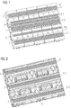
- Fig. 1 is an embodiment of a contact-protected base plate module 1, which can be used in the power busbar system according to the invention, shown in a slightly perspective view.
- touch-protected base plate module 1 consists of a cover plate 2 and a lower part 3, both firmly together are connected.
- the upper part or the cover plate 2 is clipped onto the lower part 3 by means of clip connections.
- the upper part or the cover plate 2 is firmly screwed to the lower part 3.
- the upper part or the cover plate 2 of the touch-protected base plate module 1 is firmly welded to the lower part 3 of the touch-protected base plate module 1 after manufacture.
- the upper part or the cover plate 2 is riveted or glued to the lower part 3 of the touch-protected base plate module 1.
- Both the upper part 2 and the lower part 3 consists of an electrically insulating material.
- the upper part 2 and the lower part 3 made of a flame-retardant plastic.
- the electrically insulating flame-retardant plastic of the upper part 2 and the lower part 3 of the touch-protected base plate module 1 has a relatively high thermal conductivity for dissipating heat.
- touch-protected base plate module 1 serves to receive elongated and electrically conductive busbar modules 6, as shown in the Fig. 3A to 3D are shown.
- the busbar modules 6 each have a plurality of uniformly spaced contact openings 5 of a contact opening grid.
- the electrical connection contacts 13 of a device 11 to be connected can be plugged into contact openings 5 of the contact opening grid of the electrically conductive current busbar modules 6 contained in the base plate module 1 for the purpose of establishing an electrical connection.
- Fig. 1 shown touch-protected base plate module 1 serves to receive elongated and electrically conductive busbar modules 6, as shown in the Fig. 3A to 3D are shown.
- the busbar modules 6 each have a plurality of uniformly spaced contact openings 5 of a contact opening grid.
- the electrical connection contacts 13 of a device 11 to be connected can be plugged into contact openings 5 of the contact opening grid of the electrically conductive current busbar modules 6 contained in the base plate module 1 for the purpose of
- connection contacts 13 are surrounded on both sides by contact protection ribs, which protect the connection contacts 13 from mechanical damage.
- the devices 11 to be connected include, for example, motor protection switches, circuit breakers, fuse holders, circuit breakers, electronic devices or other switching devices of a power distribution system.
- the electrical devices 11 can be plugged directly onto the base plate module 1 without the need for adapter devices or the like.
- the devices or switching devices 11 each have a housing, on whose underside preferably V-shaped or finger-shaped connecting contacts 13 are mounted, as in the Fig. 4A, 4B shown. These connection contacts 13 serve to establish an electrical connection with the electrically conductive busbar modules 6 present within the contact-protected baseplate module 1.
- the connection contacts 13 of the devices 11 are designed to be self-resilient in one possible embodiment. In a further possible embodiment, the connection contacts 13 of the devices 11 to be connected are externally sprung.
- FIG. 1 illustrated embodiment of a touch-protected base plate module 1 is provided for three parallel busbars of a busbar system. Accordingly, the front side or the cover plate 2 of the contact-protected base plate module 1 has three rows 4-1, 4-2, 4-3 of through-openings 7.
- the connection contacts 13 of the devices 11 are designed such that that they can be passed through the through-openings 7 of the cover plate or the upper part 2 of the touch-protected base plate module 1 and after passing through in directly underlying correspondingly arranged contact openings 5 of a predetermined contact opening grid of the electrically protected Stromplotschienenmodule 6 enclosed by the insulating touch-protected base plate module 1 can be inserted.
- busbar modules 6 In the contact-protected base plate module 1 of the busbar system according to the invention, specially shaped or formed busbar modules 6 can be used.
- the electrically conductive busbar modules 6 are busbar modules with contact openings 5, ie the busbar modules 6 each have a plurality of uniformly spaced contact openings 5 of a predetermined contact opening grid.
- the contact openings 5 and the passage openings 7 are slot-shaped in one embodiment. Alternatively, the contact openings 5 and the passage openings 7 are circular, elliptical, square or triangular in shape.
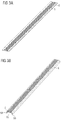
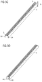
- FIGS. 3A, 3B . 3C, 3D show various embodiments of the electrically conductive busbar modules 5, which can be used in the current busbar system according to the invention.
- the contact openings 5 are slit-shaped and form contact slots.
- Fig. 3A shows a first embodiment of an electrically conductive busbar module 6, which can be used in the current busbar system according to the invention.
- the busbar module 6 is made of an electrically conductive material, such as copper.
- the contact openings 5 have a possible embodiment, a distance of 4.5 mm and are 2.2 mm wide.
- the contact openings 5 are contact slots and in one possible embodiment have a slot length of approximately 15 mm. In alternative embodiments, other dimensions and pitches of the contact openings 5 are possible.
- the connection contacts 13 can either pick up current or voltage from the busbar 6 or feed current or voltage into the busbar 6.
- the electrically conductive busbar module 6 is formed flat.
- the busbar module 6 has a U-shaped transverse profile, wherein two opposite side cheeks 6A, 6B are connected to each other via a connecting web 6C.
- the connecting web 6C In the connecting web 6C, the contact openings or contact slots 5 of the contact opening grid for inserting spring-loaded electrical connection contacts of a device to be connected 11 are provided.
- the U-shaped transverse profile with the two opposite side cheeks 6A, 6B is preferably designed for conducting an electric current with a predetermined maximum current amplitude I max .
- the maximum rated current of the busbar system is up to about 250 amperes depending on the expansion stage.
- the leg lengths H of the two side cheeks or side legs 6A, 6B of the U-shaped busbar module 6 may vary depending on the application.
- Fig. 3C shows a further embodiment of an electrically conductive busbar module 6 with respect to the embodiment in Fig. 3B longer side cheeks or side legs 6A, 6B.
- the height H and the width B of the U-shaped cross-sectional profile busbar module 6 may vary in various embodiments and are selected depending on the particular application current or maximum rated current of the busbar system.
- Fig. 3D shows a further possible embodiment of an electrically conductive busbar module 6, as it can be used in the current busbar system according to the invention.
- the two ends of the two opposite side legs 6A, 6B are folded to each other, so that there is a nearly annular cross-sectional profile for the busbar module 6.
- Fig. 4A shows a further embodiment of an electrically conductive busbar module 6 with existing evenly spaced contact openings or contact slots 5, in each of which various types of electrical connection contacts 13 different types of electrical equipment 11 can be inserted.
- Fig. 4A shows six different embodiments 13a to 13f for possible electrical connection contacts 13, which through the through openings 7, in particular through slots, into the contact slots 5 of a busbar module 6 can be inserted.
- Fig. 4B shows the various variants 13a to 13g of the electrical connection contacts 13-i in the unplugged state.
- Fig. 2 shows that in Fig. 1 illustrated embodiment of a touch-protected base plate module 1 with removed cover or remote cover plate 2, so that the different current busbar modules used in the touch-protected base plate module 1 6-1, 6-2, 6-3 are visible.
- three different electrically conductive busbar modules 6-1, 6-2, 6-3 are inserted or inserted into the lower part 3 of the base plate module.
- the three different electrically conductive busbar modules 6 are provided for three different current phases L1, L2, L3 of a multi-phase power supply system.
- busbar modules 6-i can one of the in the FIGS. 3A to 3D assume cross-sectional shapes.
- the touch-protected base plate module 1 is preconfigured in its manufacture for the particular application of the busbar system. Suitable busbars 6-i with a suitable cross section, which is suitable for the required rated current, and / or suitable contact opening grid are inserted into the lower part 3 of the base plate module 1 and then the upper part or the cover plate 2 is firmly connected to the lower part 3.
- the upper part 2 is inextricably connected to the lower part 3, for example by welding, so that a user himself with tool the upper part 2 can not remove from the lower part 3.
- the upper part 2 is firmly connected to the lower part 3 with a fastening means, for example with screws, so that a user still has the possibility with a tool, in particular a screwdriver, to remove the upper part 2 again from the lower part 3.
- a fastening means for example with screws
- the user or customer has the opportunity to exchange the electrically conductive busbar modules 6 within the touch-protected base plate module 1 for different applications or systems.
- the contact-protected base plate module 1 has a plurality of current busbar modules arranged therein, wherein a current busbar module 6-1, 6-2, 6-3 is provided for each current phase L1, L2, L3.
- a busbar which is provided for a current phase L of the multiphase busbar system, is formed by a plurality of mutually end-side juxtaposed busbar modules 6-i within the touch-protected baseplate module 1.
- the touch-protected baseplate module 1 can be connected by means of mechanical connecting elements to further contact-protected baseplate modules 1 for expanding the busbar system.
- busbar modules 6 contained within the various touch-protected baseplate modules 1 are electrically contacted with each other to form in this way a continuous electrically conductive long busbar.
- the upper part or the cover plate 2 shows in the installed position to the front and forms the front side for a user who inserts and removes devices 11 into the base plate module 1.
- touch-protected base plate module 1 can be installed vertically or horizontally within a control cabinet or integrated therein.
- the touch-protected base plate module 1 may have predetermined standard lengths or standard dimensions in a possible embodiment variant, for example standard lengths of 135 mm, 225 mm, 315 mm, 405 mm or 495 mm.
- the upper side or the cover plate 2 of the touch-protected base plate module 1 has a plurality of rows 4-1, 4-2, 4-3 of through openings 7, which are located directly above the contact openings 5 of the busbar modules 6-1, 6 contained in the base plate module 1. 2, 6-3, as in Fig. 2 are shown lie.
- the lower part 3 of the touch-protected base plate module 1 preferably has on its rear side fastening means for fastening the touch-protected base plate module 1 on a mounting rail, in particular a DIN mounting rail, and / or on a mounting plate.
- the current busbars are covered with the upper part 2 or a contact-protected cover cover, which has the same slot grid as the slotted busbars 6.
- two rectangular shaped contours or contact slots 5 of the busbar modules 6 are used for a terminal contact 13 of a device 11 so that the device are electrically connected by plugging with the busbar system.
- the terminal contacts 13 have this in a possible variant finger-shaped contacts which engage in two juxtaposed contact slots 5 of the busbar module 6 or engage behind.
- electrical connection contacts 13-i of the electrical devices thus serve not only the electrical contacting of the busbar modules 6, but at the same time for mechanical connection or mechanical support of the devices connected to the busbar system 11.
- the mechanical fixation is taken over by contact protection ribs and the electrical connection contact 13 thereby relieved and protected.
- the touch-protected base plate module 1 has a cover plate or a top part 2 with three mutually parallel rows 4-1, 4-2, 4-3 of through-openings 7, which serve to pass through terminals 13 of electrical appliances 11.
- the cover plate or the upper part 2 of the touch-protected base plate module 1 in the in Fig. 1 illustrated embodiment of two rows 8-1, 8-2 with contours or slots, which are provided for receiving latches of the installed devices 11 so that they can be mechanically connected to the touch-protected base plate module 1.
- the lock secures the devices 11 against removal to the front.
- the contact protection ribs secure the device 11 in the direction of gravity.
- a further series 9 of contours or slots provided in the so-called Verpolstoffrippen 32 of the connected devices 11 can dip.
- the contours or slots of the row 9 within the upper part 2 of the touch-protected base plate module 1 prevent electrical equipment can be incorrectly or incorrectly poled to the touch-protected base plate module 1 can be plugged. Due to the special arrangement of the various feedthrough slots 7, the locking contours and the Verpolstoffkonturen for Verpolstoffrippen 32 of the devices 11, the entire touch-protected base plate module 1 can be equipped with electrical equipment 11 without left or right mounting space is lost.
- the following meaningful widths of the device housing namely, for example, 18 mm, 22.5 mm, 27 mm, 36 mm and 45 mm are thus obtained.
- the housing width of 18 mm is a standard measure for circuit breakers.
- a housing width of 22.5 mm have various electronic or electrical devices 11 or modules, 22.5 and devices for feeding electrical current ..
- switching devices 11 with a standard device width of their Housing of 27 mm, 36 mm or 45 mm or 54 mm known.
- the device interfaces to the touch-protected base plate module 1 are preferably designed such that all devices 11 with such conventional device widths without spacing on the touch-protected base plate module 1 can be strung together gapless, so that no space is lost at the front or end face of the touch-protected base plate module 1.
- the contact-protected current busbar system thus offers a highly integrated prefabricated system Power busbar system that can be assembled from touch-protected base plate modules 1, which already includes the busbars and ensures safe contact protection.
- the contact-protected baseplate module 1 has an IP20 contact protection.
- the contact-protected baseplate module 1 has an IP30 contact protection. Additional covers can be used to achieve touch protection IP40. Through the series 9 of coding or Verpolstoffschlitzen an erroneous rotation of the devices to be connected 11 can be reliably prevented.
- the current busbar modules 6 used in the busbar system according to the invention have, in comparison to conventional busbars integrated therein contact openings 5, which ensure electrical contacting of the devices with the busbar system.
- the devices can be connected to and removed from the busbar system without the use of tools. Only a slot screwdriver can be used if necessary for the actuation of a latching element of the device.
- the touch-protected baseplate module 1 can have shock-absorbing and / or vibration-damping connecting elements for the mechanical support of devices. These can be attached to the mechanical interfaces.
- the contact-protected baseplate module 1 can also be fitted or integrated with feed-in components for supplying power or supplying voltage to the busbar system. Farther a locking against occurring vibrations and against unintentional removal can be provided.
- heat sink structures for inserting cooling elements are provided in the plastic housing or in the contact-protected base plate module 1.
- the touch-protected base plate module 1 may have ventilation openings in a possible embodiment, so that air can enter or leave the touch-protected base plate module 1.
- the touch-protected base plate module 1 in one possible embodiment has openings for cable feedthroughs.
- the touch-protected baseplate module 1 contains, in addition to busbar modules 6, electrical data lines for communication between the devices connected to the busbars. Between the busbars data lines can be routed for networking, in which the devices 11 are connected to each other and communicate with each other. Furthermore, special plug contours can be provided for contacting the data lines provided in the touch-protected base plate module 1.
- the devices connected to the busbar system communicate by means of powerline communication PLC (PowerLAN or dLAN) with each other directly over the current busbars 6 contained in the touch-protected baseplate module 1.
- the devices 11 inserted in the busbars each have a transceiver for replacement of informational data by means of Powerline Communication PLC via the electrically conductive busbar modules 6.
- the data transmission of the frequency range from 50 to 500 kHz and / or 16 MHz to 30 MHz are used. In the lower frequency range data rates of up to 2.5Mbit / sec can be achieved, while in the upper frequency range up to 14Mbit / sec can be achieved.
- the devices 11 connected to the busbar system communicate with each other via a separate wireless radio interface.
- the communication between the connected devices 11 takes place via different communication channels by means of electrical data lines, by means of powerline communication and / or by means of wireless communication via radio interfaces.
- the radio interfaces include, for example, a WLAN, Bluetooth, ZigBee or RFID interface.
- the devices 11 communicate, inter alia, also with external transmitters and receivers, such as smartphones, in order to be able to exchange and set data and parameters.
- measuring modules for current and voltage measurement are provided in the touch-protected baseplate module 1 to the busbar modules 6 contained in the baseplate module 1. These measurement modules are used in a possible embodiment for the detection of overcurrents or short circuits within the busbar system.
- the touch-protected baseplate module 1 contains, in addition to busbar modules 6, electrical supply lines for transmitting auxiliary supply voltages for the measuring modules provided in the contact-protected baseplate module 1 or for the devices 11 connected to the busbar modules 6.
- cooling lines or cooling chimneys for removing waste heat from the interior of the touch-protected base plate module 1 are provided within the touch-protected base plate module 1 and extend vertically in the installed state of the base plate module 1.
- the upper part 2 and the lower part 3 of the contact-protected base plate module 1 consist of a thermally conductive plastic for better dissipation of heat arising.
- the touch-protected baseplate module 1 can be expanded with additional modules for neutral conductors, N or PE conductors or for data lines. In one possible embodiment, these additional modules can be attached to the touch-protected baseplate module 1 at the top and / or bottom. For attachment special contours are provided on the base plate module 1. These contours are designed so that an extension with additional modules is also possible if the base plate module 1 is already installed on a DIN rail or a mounting plate in the control cabinet.
- the touch-protected base plate module 1 in a cabinet housing to Integrated recording of a plurality of devices 11, which are inserted into the contact slots of the contact opening grid of the current collection bus modules 6 contained in the touch-protected base plate module 1.
- the busbar system has a modular design.
- the busbar system has at least one power feed module which is provided for feeding different electric current phases L into the bus bar system.
- the power supply module feeds various electric current phases L into the current collecting rails, which are arranged in parallel in the contact-protected base plate module 1 and each composed of at least one current busbar module 6.
- the power supply module may have a contact-protected connection pin with electrical connection contacts for insertion into contact slots of a busbar module 6 for each current busbar arranged in parallel in the contact-protected baseplate module 1.
- the current busbar system may comprise contact-protected bridge modules in a modular embodiment.
- a contact-protected bridge module of the busbar system on both sides each have a plurality of terminals for insertion into contact openings 5, which are located at the ends of two each covered by a cover module longitudinally formed and electrically conductive adjacent busbar modules 6 a busbar of the busbar system.
- the contact-protected bridge module preferably has on both sides centrally arranged through openings 7 for passage of terminal contacts 13 of devices that are plugged for connecting the device to the busbar system in contact openings 5 of the contact opening grid of the two assembled by the bridge module electrically conductive busbar modules 6.
- the bus bar system may include touch-protected end cap modules.
- a contact-protected end cap module of the busbar system in this case has a plurality of terminals for insertion into contact openings 5 of the contact opening grid, which are located at one end of a covered by a contact-protected cover module elongated and electrically conductive busbar module of a busbar of the busbar system.
- the contact-protected end cap module preferably has centrally arranged through openings 7 for the passage of connection contacts which can be inserted for connecting a device to the busbar system in contact openings 5 of the contact opening grid, which lie below the contact-protected end cap module.
- the busbar system has in the modular design variant touch-protected elongated cover modules.
- the contact-protected elongated cover module of the busbar system preferably has at its two ends in each case a recess which is provided an end cap module, a side of a bridge module or a terminal pin of a power supply module of the busbar system in contact openings 5 of the contact opening grid electrically conductive busbars 6 of the busbar system flush with the shape to form a contact-protected cover plate of the touch-protected base plate module 1 insert.
- a device 11 to be connected to the busbar system can be snapped into the current busbars of the busbar system assembled from the busbar modules 6 for the purpose of establishing a mechanical connection.
- the device 11 to be connected to the busbar system additionally has latching means which can be latched onto latching webs of the contact-protected baseplate module 1 of the busbar system running parallel to the busbars 6.
- the latching means of the device to be connected to the busbar 11 have in one possible embodiment latching lugs which are mounted for unlocking and locking the mechanical connection to a manually operable latching means of the device to be connected 11 to the busbars of the busbar system within a housing of the device to be connected 11th is laterally displaceable.
- the device 11 which can be connected to the busbar system is an electrical, electronic or electromechanical device which has electrical connection contacts for producing an electrical connection with the busbar system and latching means for producing an additional mechanical connection. Furthermore, reverse polarity protection ribs for correct connection to the busbar system can be provided on the housing of the electrical device 11.
- the invention accordingly provides, according to a further aspect, a device 11, in particular a switching device, such as a motor protection switch or a circuit breaker, which is suitable for a current busbar system according to the invention and preferably has a housing which via suitable electrical connection contacts 13 has, which can be inserted into the contact openings 5 of the contact opening grid.
- a switching device such as a motor protection switch or a circuit breaker
- the device 11 according to the invention has in one possible embodiment on its housing 12 in addition Verpoltikrippen 32, which prevent erroneous insertion or connection to the busbar system.
- the device 11 according to the invention additionally has mechanical locking means 16 for producing a mechanical connection to the busbar system.
- the connectable device 11 may be a motor control device, a protective device, a measuring device, an adapter device or another device in a possible embodiment.
- the touch-protected base plate module 1 of the busbar system has first current busbar modules for different current phases L of the busbar system and second differently shaped current busbar modules for protective conductors P, N of the busbar system.
- the first current busbar modules for the current phases L preferably have a U-shaped transverse profile with two mutually opposite side cheeks, which are designed for the electrical conduction of a current phase L having a predetermined maximum current amplitude.
- the touch-protected baseplate module 1 can be integrated in a small distribution housing.
- the lower part 3 of the touch-protected base plate module 1 is integrated into the small distribution housing.
- the entire touch-protected base plate module 1 is integrated into the small distribution box or attached thereto.
- the power supply to the busbar system can be done from the front of the base plate module 1 or from the rear side of the base plate module 1. This also applies to base plate modules that are not integrated into a small distribution box.
- Fig. 5 shows in perspective a further embodiment of a contact-protected base plate module 1, as it can be used in the current busbar system according to the invention.
- the touch-protected base plate module 1 similar to that in Fig. 1 illustrated base plate module via a central or centrally arranged core component, on the back or rear part 3 are mechanical fastening means for attachment to a support rail or a mounting plate.
- the touch-protected base plate module 1 has in the illustrated embodiment in the middle of three parallel rows 4-1, 4-2, 4-3 with a plurality of uniformly spaced through-openings 7, under each of which is an associated same shaped contact opening 5 of the contact hole grid.
- the touch-protected base plate module 1 thus includes a total of seven parallel arranged busbars integrated therein.
- the two upper busbar bus modules or busbars and the two lower busbar bus modules are or busbars in separate additional modules 26, 27, which are mechanically connected to a central touch-protected base plate module 1, as for example in Fig. 1 is shown.
- the attachment of additional modules or crossbars 26, 27 is in the Figures 19A, 19B, 19C shown.
- the illustrated example corresponds to a base plate module 1 with four additional modules 26, 27. How to Fig. 5 can recognize the current busbar system can thus be extended by additional modules 26, 27 for further busbars in a simple manner.
- the number of current busbars provided in parallel in the additional modules 26, 27 may vary in different embodiments of the busbar system.
- the additional modules 26, 27 can also be mounted or engaged in the installed state of the base plate module 1.
- Fig. 6 shows a front view of the upper part 2 of in Fig. 5 illustrated embodiment of a base plate module. 1
- Fig. 7 shows in perspective an embodiment of a device which can be connected to the busbar system 11.
- the device 11 has a specially shaped housing 12, on the underside of which plug-in contacts 13-1, 13-2, 13-3 suitable for the contact slots for three current phases L1, L2, L3 are located.
- a connection contact 13 is always protected by two contact protection ribs. However, two or three adjacent plug contacts are possible per phase. These are protected with contact protection ribs, as in Fig. 4A shown schematically.
- the attached to the underside of the housing 12 of the device 11 terminal contacts 13-i of the device 11 are in a possible embodiment according to one of the in Fig. 4A formed illustrated six variants.
- the device 11 has three connection contacts 13-1, 13-2, 13-3 for three current phases L1, L2, L3.
- the device 11 may have a different number of terminal contacts 13 for current phases and / or neutral.
- Fig. 8 perspectively illustrates the insertion of the in Fig. 7 illustrated device 11 in three corresponding rows 4-1, 4-2, 4-3 of a touch-protected base plate module 1 of the current busbar system according to the invention.
- the device 11 can be placed in a simple manner on the upper part 2 of the touch-protected base plate module 1 and then plugged into the contact-protected base plate module 1 with relatively little effort.
- the connection contacts 13-1, 13-2, 13-3 are passed through the lead-through openings 7 of the terminal contact rows 4-i and then inserted into the immediately underlying contact openings 5 of the three current busbar modules 6 contained in the base plate module 1, so that an electrical connection is made ,
- Fig. 9 shows the electrical device 11 with its housing 12 in the inserted state on the touch-protected base plate module 1 from the front.
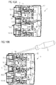
- FIGS. 10A, 10B show sectional views through the housing 12 of the device 11 to illustrate an embodiment of the device 11.
- the device 11 has a latching element 14.
- the locking element 14 is shown in the locked state.
- the locking element 14 of the device 11 are moved to remove the device 11 from the touch-protected base plate module 1.
- the device 11, as in Fig. 10A represented on the underside of its housing 12 via locking lugs 16-1, 16-2, which engage behind the cover plate 2 of the base plate module 1 in the locked state.
- the latching lugs 16-1, 16-2 can also engage in latching webs of the contact-protected baseplate module 1.
- the latching component 14 as in Fig. 10B illustrated, levered up, so that the detents 16-1, 16-2 from the cover and / or the locking rails of the base plate module 1 solve and the device 11 can be removed from the touch-protected base plate module 1.
- the device 11 can without actuation of the locking component 14 (position locking element as in Fig. 10A shown) are placed on the base plate.
- the latching component 14 in the device 11 has a foreign or inherent resilience, which ensures that the latching component 14 always in the position according to Fig. 10A is pressed.
- a mounted device 11 can only be removed from the touch-protected base plate module 1 after the latching component 14 has been actuated. As a result, unintentional detachment of a device 11 from the touch-protected base plate module 1 can be reliably prevented.
- Fig. 11 shows in perspective a view of the lower part 3 of the touch-protected base plate module 1 from behind or from the back.
- the lower part 3 of the base plate module 1 has a recess or contour 10 for placing the touch-protected base plate module 1 on a mounting rail 23. This recess extends centrally in the middle Longitudinal direction of the base plate module 1, as in Fig. 11 shown.
- the base plate module 1 can be placed on a mounting rail, in particular a DIN rail, and then snapped onto the mounting rail.
- the lower part 3 of the contact-protected base plate module 1 has a plurality of latching components 17, as in FIG Fig. 11 shown.
- the non-contact base plate module 1 on its rear side four provided for a support rail 23 latching components 17-1, 17-2, 17-3, 17-4.
- Fig. 12 shows a rear view of the lower part 3 of a touch-protected base plate module 1. It can be seen four adjacent locking components 17-i, the fastening means 10 for locking on a support rail 23, in particular top hat rail form.
- Fig. 12 shows a basic module with four additional modules. The locking component is extended with extension elements.
- Fig. 13 shows a perspective view of the in Fig. 12 illustrated Rastbauelement 17-4, which is identical to the other three latching components 17-1, 17-2, 17-3, with extension elements of the latching device.
- the Fig. 14 shows a view on the in Fig. 13 illustrated latching device 17-i from behind.
- the locking component 17, which serves for mounting the touch-protected base plate module 1 to a mounting rail, has a deflection lever 18 which is injection-molded onto the latching component 17 via a meander-shaped connection 19 and has a central bearing point.
- the locking component 17 also has integrated return springs 20, 21. Alternatively, a foreign spring is possible by compression springs.
- the locking component 17 has an operating point 22 for actuation by a user or operator.
- the latching component 17 is designed in such a way that, by means of the reversing lever 18 molded onto the latching component 17, an operating movement made on one side is deflected in such a way that both top-hat rail locks release from the relevant top-hat rail.
- the reversing lever 18 is mounted on a rotation axis.
- Locking hooks 24A, 24B are provided on the latching component, which engage behind the DIN rail or mounting rail 23 in the locked state, so that the contact-protected baseplate module 1 can no longer be removed from the mounting rail or DIN rail 23.
- the molded-on latching hook 24B moves uniformly downwards and at the same time the deflecting lever 18 is moved out of the in Fig. 14 rotatably moved about the axis of rotation shown, whereby the other latching hook 24A moves in the opposite direction, so that the touch-protected base plate module 1 can be removed from the top hat rail 23. If the latching element is pulled further, the latching element snaps into a parked position, so that the user must actively push the latching elements back into the locked position during the renewed assembly.
- the operation of the fastening means 10 formed by the latching components 17-i can be carried out by a user in a simple manner by actuating the operating points 22 on the edge of the contact-protected base plate module 1.
- An advantage of the double-sided locking element is that the base plate module 1 can be placed frontally without tipping on the top hat rail. Thus, even very high base plate modules 1 can be placed without problems.
- Figures 15A, 15B, 15C, 15D show a mounted on a support rail 23 touch-protected base plate module 1 of the back and from the side.
- the base plate module 1 has three latching components 17-1, 17-2, 17-3.
- the control points 22 of the latching components 17-i are provided at the top of the touch-protected base module 1.
- the points of contact 22 of the latching components 17-i can thus be provided at the upper or lower edge of the touch-protected basic module 1 for easy operation by a user.
- the latching components 17-i allow the touch-protected base plate module 1 to be set up frontally without tipping on the mounting rail 23 and removed again.
- the operation of the latching components 17-i is possible with or without the use of a tool.
- the support rails 23 may have different mounting rail heights in various embodiments.
- the operation of the latching components 17-i has the advantage that they can be operated without disassembly devices or products of the touch-protected base plate module 1.
- the latching function of the latching components 17-i has a parking position.
- the support rail 23 is encompassed by the latching components 17-i on both sides in the locked state.
- the direction of movement of the latching lugs is deflected by a tilting mechanism of the latching component 17.
- the operating function is transmitted to the respective additional element when the touch-protected baseplate module 1 or crossbars are plugged on.
- the number of latching components 17 required depends on the size or length of the touch-protected foundation module 1 as well as the size or weight of the devices 11 mounted or mountable thereon. The more devices 11 are to be mounted to the base plate module 1 and the higher their expected weight, the greater the number of latching components 17-i attached to the rear side of the touch-protected foundation module 1.
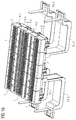
- Fig. 16 shows a further embodiment of the touch-protected base plate module 1, as it can be used in the current busbar system according to the invention.
- Fig. 16 shows the attachment of the base plate module 1 on a support system from. Litze.
- Figures 17A, 17B, 17C, 17D show a further embodiment of the touch-protected foundation module 1, as can be used in the current busbar system according to the invention.
- the touch-protected foundation module 1 is mounted on a mounting plate 25.
- Fig. 17A shows in perspective a touch-protected base plate module 1, which is mounted on a mounting plate 25.
- FIG. 17B shows a front view of the mounted touch-protected base plate module 1, which is located on the mounting plate 25.
- Fig. 17C shows a sectional view through the mounted touch-protected base plate module.
- FIGS. 17D, 17E show detail views A, B from the sectional view in Fig. 17C , How to get out Fig. 17D can recognize, in a possible embodiment, a plurality of additional support column elements 26-1, 26-2, the touch-protected base plate module 1 additionally supported on the mounting plate 25.
- Fig. 17E shows how the touch-protected base plate module 1 with the mounting plate 25 can be screwed.
- the screws are added via keyhole-shaped shots in the base plate. During assembly, the screws are pre-screwed into the base plate. Subsequently, the base plate module 1 is mounted on the keyhole geometries in the screws and finally screwed from the front of the base plate module 1.
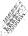
- Fig. 18A . 18B show a further mounting option of a touch-protected base plate module 1, as can be used in the current busbar system according to the invention.
- Figures 18A . 18B show a mechanical connection for the installation of further touch-protected additional modules to the touch-protected base plate module.
- 1 Fig. 18B shows a detailed view of the made mechanical connection.
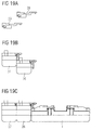
- the mechanical connection is further by the Figures 19A, 19B, 19C clarified. How to get in Fig. 19C can recognize, a touch-protected base plate module 1 is extended by further additional modules 26, 27 at one edge.
- Fig. 19C clarified. How to get in Fig. 19C can recognize, a touch-protected base plate module 1 is extended by further additional modules 26, 27 at one edge.
- FIG. 19A illustrates, in the illustrated embodiment locking slide extensions 28, 29 inserted into the additional modules 26, 27 and the two additional modules 26, 27 by means of Rastschieberverinrungs institute 28, 29 locked together, as in Fig. 19B recognizable.
- the interconnected add-on modules 26, 27 are mechanically connected to the main base plate module 1, as in FIG Fig. 19C shown. This is done using mechanical connections to connect touch-protected base plate modules 1 or additional modules with each other.
- the additional modules 26, 27 can also be mounted when the base plate module 1 is already installed on a mounting plate 25 in a cabinet.
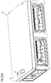
- FIGS. 20A . 20B . 20C show a further embodiment of the current busbar system according to the invention.
- the touch-protected base plate module 1 is integrated directly into a cabinet housing 29.
- the cabinet housing 29 is used to hold multiple devices or switching devices 11, which are placed and plugged into the integrated base plate module 1 and possibly locked by means of locking devices are.
- the cabinet housing 29 may, in one possible embodiment, have a removable or pivotable lid 30, as in FIG Fig. 20A shown.
- this protective cover 30 has a handle 31 for opening the control cabinet 29.
- Fig. 20B shows a view of the cabinet 29 after removal or opening of the lid 30th
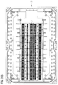
- Fig. 20B shows a view from above of the integrated in the cabinet housing 29 base plate module. 1
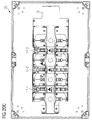
- Fig. 20C shows a view from behind on the in Fig. 20A
- fastening means 10 for fastening the cabinet directly to a mounting rail 23, in particular a DIN rail.
- the mechanical fastening means have in the illustrated embodiment, three locking components 17-i, as already associated with Fig. 14 have been described in detail.
- Fig. 21 shows in perspective a view of a further embodiment for a control cabinet or a cabinet housing 29 with a touch-protected base plate module integrated therein 1.
- the touch-protected base plate module 1 can be mounted on a mounting plate 25, a DIN mounting rail or other fastening system.
- the touch-protected base plate module 1 is preferably available in various lengths of 135 mm to 495 mm.
- a combination with conventional busbars is possible.
- With additional slot covers the contact protection can be further increased according to IP40.
- the feed Current or voltage can be frontal or backward.
- the base plate module 1 is molded or molded in one possible embodiment of the cabinet housing. Alternatively, the base plate module 1 is clipped into the cabinet housing or snapped into the cabinet housing.
- the additional modules 26, 27 can, as in the Figures 5 . 6 shown, have through openings 7, which lie on the front or front side of the extended base plate module 1.
- the additional modules 26, 27 may also be designed in such a way that they have through openings 7 which lie on the rear side of the extended base plate module 1.
- the additional modules 26, 27 have through openings 7 at the end faces.
- contact plug can be introduced, the current busbar modules 6 contact, which are included in the additional modules or crossbars 26, 27. These contact plug serve in a possible embodiment of the current and / or voltage supply to the busbar system.
- connection contacts 13 of devices 11 or plug contacts of connection plugs are passed through feedthrough slots 7 of the base plate module 1 or through feedthrough slots 7 of an additional module 26, 27 and touch with their front side in the base plate module 1 or the additional module 26, 27 power bus for electrical Contacting the busbar.
- conventional Power busbars are used without contact openings.
- the base plate module 1 in a further embodiment also has the lower part 3 of the base plate module 1 via feedthrough slots 7 for passing through contacts 13 or plug contacts of plugs.
- the base plate module 1 in one possible embodiment has bilateral, i. at the front and at the back, rows 4-i of feed-through slots 7 for attaching devices 11 and supply plugs.
- a base plate module 1 which is symmetrical and has on both sides through slots 7, similar to an electronic circuit board attached with its front side in the cabinet and fitted from both sides with devices 11 or supply plugs.
Landscapes
- Power Engineering (AREA)
- Engineering & Computer Science (AREA)
- Mounting Components In General For Electric Apparatus (AREA)
- Connector Housings Or Holding Contact Members (AREA)
- Distribution Board (AREA)
- Connections Arranged To Contact A Plurality Of Conductors (AREA)
- Patch Boards (AREA)
- Installation Of Bus-Bars (AREA)
- Clamps And Clips (AREA)
- Switch Cases, Indication, And Locking (AREA)
- Multi-Conductor Connections (AREA)
- Details Of Connecting Devices For Male And Female Coupling (AREA)
- Connection Or Junction Boxes (AREA)
- Casings For Electric Apparatus (AREA)
Priority Applications (18)
| Application Number | Priority Date | Filing Date | Title |
|---|---|---|---|
| ES16169977T ES2811975T3 (es) | 2016-05-17 | 2016-05-17 | Sistema de barras colectoras |
| EP16169977.2A EP3246995B1 (fr) | 2016-05-17 | 2016-05-17 | Systeme de barres omnibus |
| PL16169977T PL3246995T3 (pl) | 2016-05-17 | 2016-05-17 | System szynoprzewodów |
| PL16191898T PL3247010T3 (pl) | 2016-05-17 | 2016-09-30 | Urządzenie do zabezpieczania przedmiotu na szynie |
| EP16191898.2A EP3247010B1 (fr) | 2016-05-17 | 2016-09-30 | Dispositif de fixation d'un objet sur un rail |
| ES16191898T ES2831713T3 (es) | 2016-05-17 | 2016-09-30 | Dispositivo para sujetar un objeto en un riel |
| ES17153517T ES2959562T3 (es) | 2016-05-17 | 2017-01-27 | Dispositivo para un sistema de barras colectoras de energía |
| EP17153517.2A EP3246996B1 (fr) | 2016-05-17 | 2017-01-27 | Appareil pour un système de rail de barre omnibus |
| PCT/EP2017/060826 WO2017198484A1 (fr) | 2016-05-17 | 2017-05-05 | Système de barres omnibus |
| US16/099,617 US10879642B2 (en) | 2016-05-17 | 2017-05-05 | Busbar system |
| CN201780031018.XA CN109155472B (zh) | 2016-05-17 | 2017-05-05 | 母线系统 |
| CN201780030499.2A CN109155471A (zh) | 2016-05-17 | 2017-05-16 | 用于母线系统的装置 |
| PCT/EP2017/061668 WO2017198642A1 (fr) | 2016-05-17 | 2017-05-16 | Appareil pour système de barres omnibus |
| US16/099,859 US10700464B2 (en) | 2016-05-17 | 2017-05-16 | Device for a busbar system |
| CN202111599139.9A CN114530716A (zh) | 2016-05-17 | 2017-05-16 | 用于母线系统的装置 |
| CN201780030678.6A CN109155505B (zh) | 2016-05-17 | 2017-05-16 | 用于将物体固定于导轨上的装置 |
| US16/099,588 US10923850B2 (en) | 2016-05-17 | 2017-05-16 | Device for securing an object on a rail |
| PCT/EP2017/061675 WO2017198643A1 (fr) | 2016-05-17 | 2017-05-16 | Dispositif pour maintenir un objet sur un rail |
Applications Claiming Priority (1)
| Application Number | Priority Date | Filing Date | Title |
|---|---|---|---|
| EP16169977.2A EP3246995B1 (fr) | 2016-05-17 | 2016-05-17 | Systeme de barres omnibus |
Publications (2)
| Publication Number | Publication Date |
|---|---|
| EP3246995A1 true EP3246995A1 (fr) | 2017-11-22 |
| EP3246995B1 EP3246995B1 (fr) | 2020-05-13 |
Family
ID=56014869
Family Applications (3)
| Application Number | Title | Priority Date | Filing Date |
|---|---|---|---|
| EP16169977.2A Active EP3246995B1 (fr) | 2016-05-17 | 2016-05-17 | Systeme de barres omnibus |
| EP16191898.2A Active EP3247010B1 (fr) | 2016-05-17 | 2016-09-30 | Dispositif de fixation d'un objet sur un rail |
| EP17153517.2A Active EP3246996B1 (fr) | 2016-05-17 | 2017-01-27 | Appareil pour un système de rail de barre omnibus |
Family Applications After (2)
| Application Number | Title | Priority Date | Filing Date |
|---|---|---|---|
| EP16191898.2A Active EP3247010B1 (fr) | 2016-05-17 | 2016-09-30 | Dispositif de fixation d'un objet sur un rail |
| EP17153517.2A Active EP3246996B1 (fr) | 2016-05-17 | 2017-01-27 | Appareil pour un système de rail de barre omnibus |
Country Status (6)
| Country | Link |
|---|---|
| US (3) | US10879642B2 (fr) |
| EP (3) | EP3246995B1 (fr) |
| CN (4) | CN109155472B (fr) |
| ES (3) | ES2811975T3 (fr) |
| PL (2) | PL3246995T3 (fr) |
| WO (3) | WO2017198484A1 (fr) |
Cited By (5)
| Publication number | Priority date | Publication date | Assignee | Title |
|---|---|---|---|---|
| CN111884073A (zh) * | 2020-07-23 | 2020-11-03 | 广东电网有限责任公司 | 分接箱通信模块的固定装置 |
| DE102020106085A1 (de) | 2020-03-06 | 2021-09-09 | Phoenix Contact Gmbh & Co. Kg | Anschlussvorrichtung und elektromechanische Baugruppe |
| EP3766146B1 (fr) | 2018-03-15 | 2022-12-14 | Wöhner Besitz GmbH | Système de barre omnibus à protection tactile |
| RU2843153C1 (ru) * | 2024-10-04 | 2025-07-07 | Акционерное общество "Диэлектрические кабельные системы" | Щиток для распределения электроэнергии |
| DE102024134419B3 (de) * | 2024-10-07 | 2025-09-18 | AUO Corporation | Energieverteilungssystem |
Families Citing this family (22)
| Publication number | Priority date | Publication date | Assignee | Title |
|---|---|---|---|---|
| PL3490349T3 (pl) * | 2017-11-23 | 2022-12-27 | Wöhner GmbH & Co. KG Elektrotechnische Systeme | Aparat do zasilania szynoprzewodowego |
| GB2574727A (en) * | 2018-06-13 | 2019-12-18 | Eaton Intelligent Power Ltd | Electrical panelboard and plug-in device for such a panelboard with improved electrical insulation and modularity |
| US11095117B2 (en) * | 2018-07-20 | 2021-08-17 | Vertiv Corporation | DC-DC converters having DIN rail mounts |
| CN109244878B (zh) * | 2018-09-29 | 2020-09-11 | 陕西捷亚慧电子智能科技有限公司 | 一种具有防雷击功能的变电箱及配电箱的防雷方法 |
| DE102019109638B4 (de) | 2019-04-11 | 2021-11-18 | Rittal Gmbh & Co. Kg | Schaltschrankanordnung mit einem Schaltschrankrahmengestell und einem auf einer Montageplatte montierten mehrpoligen Berührungsschutzmodul |
| CN112576869A (zh) * | 2019-09-27 | 2021-03-30 | 台达电子工业股份有限公司 | 电源模块 |
| BE1028102B1 (de) * | 2020-02-28 | 2021-09-27 | Phoenix Contact Gmbh & Co | Stromschienenadapter zur elektrischen Verbindung wenigstens eines Steckmoduls mit wenigstens einer Stromschiene |
| US11158998B1 (en) | 2020-04-27 | 2021-10-26 | Abb Schweiz Ag | Heat sink for power supply panel |
| EP3926770A1 (fr) * | 2020-06-19 | 2021-12-22 | Wöhner Besitz GmbH | Plaque de barre à bus allongée |
| EP3926774B1 (fr) * | 2020-06-19 | 2022-10-26 | Wöhner Besitz GmbH | Plaque de barre à bus |
| CN111653996B (zh) * | 2020-06-27 | 2021-10-01 | 河北纳格新材料科技有限公司 | 一种石墨烯弱电线路与墙壁插线盒连接结构 |
| US11139639B1 (en) * | 2020-07-09 | 2021-10-05 | Ge Aviation Systems Limited | Modular power distribution assembly and method of assembly thereof |
| US11521819B2 (en) | 2020-11-20 | 2022-12-06 | Wöhner Besitz Gmbh | Fuse holder |
| EP4184732B1 (fr) * | 2021-11-22 | 2025-03-26 | Wöhner Besitz GmbH | Module d'alimentation électrique |
| DE102023117907B4 (de) * | 2023-07-06 | 2025-01-23 | Klaus Bruchmann Gmbh | Geräteträger-modul und montagetafel-system mit einem solchen geräteträger-modul |
| CN117117583B (zh) * | 2023-09-27 | 2026-01-02 | 香江科技(集团)股份有限公司 | 一种使用开放式固定支架的滑轨式末端母线及使用方法 |
| WO2025087510A1 (fr) * | 2023-10-24 | 2025-05-01 | Future Systems Besitz Gmbh | Ensemble couvercle de protection tactile avec repères de position et dispositif d'installation électrique |
| WO2025087511A1 (fr) * | 2023-10-24 | 2025-05-01 | Future Systems Besitz Gmbh | Bande avec repères de position, ensemble couvercle de protection et dispositif d'installation électrique |
| EP4576459A1 (fr) * | 2023-12-20 | 2025-06-25 | Wöhner Besitz GmbH | Système de barre omnibus à protection tactile à double boîtier |
| US20250279634A1 (en) * | 2024-02-29 | 2025-09-04 | Abb Schweiz Ag | Expandable Panelboard Bus Assemblies and Methods of Assembling Same |
| DE102024111474A1 (de) * | 2024-04-24 | 2025-10-30 | Weidmüller Interface GmbH & Co. KG | Elektronikmodul mit einem Elektronikgehäuse mit einem Montagefuß |
| LU507363B1 (de) * | 2024-05-29 | 2025-12-01 | Phoenix Contact Gmbh & Co | Vorrichtung und System zur Energiemessung |
Citations (5)
| Publication number | Priority date | Publication date | Assignee | Title |
|---|---|---|---|---|
| US4567654A (en) * | 1984-04-02 | 1986-02-04 | Emhart Industries, Inc. | Bussing block |
| WO2004057716A1 (fr) * | 2002-07-15 | 2004-07-08 | Haworth, Inc. | Systeme electrique modulaire a fils rigides pour zones de bureaux |
| US20060121796A1 (en) * | 2004-12-08 | 2006-06-08 | Siemens Corporation | Electric phase bus bar |
| DE102013103544A1 (de) * | 2013-04-09 | 2014-10-09 | Block Transformatoren-Elektronik Gmbh | Klemmvorrichtung zur lösbaren Befestigung eines Gerätegehäuses an einer Profilschiene |
| EP2863496A1 (fr) * | 2013-10-18 | 2015-04-22 | Wöhner GmbH & Co. KG Elektrotechnische Systeme | Système de protection contre le contact pour barres omnibus |
Family Cites Families (65)
| Publication number | Priority date | Publication date | Assignee | Title |
|---|---|---|---|---|
| US3124403A (en) * | 1964-03-10 | Electrical bus conductor | ||
| US3018320A (en) * | 1955-06-13 | 1962-01-23 | Gen Electric | Electricity distributing conduit apparatus |
| US3009011A (en) | 1956-03-02 | 1961-11-14 | Gen Electric | Distribution system |
| US3183299A (en) | 1958-05-26 | 1965-05-11 | Gen Electric | Busway with resiliently bowed housing |
| US3182381A (en) | 1958-05-26 | 1965-05-11 | Gen Electric | Method of forming apertured hollow insulated busbars |
| DE19537528C2 (de) * | 1995-09-29 | 2000-01-13 | Krone Ag | Anschlußeinrichtung für die Fernmelde- und Datentechnik |
| US3096131A (en) * | 1961-01-03 | 1963-07-02 | Gen Electric | Electrical bus conductor |
| US3213403A (en) | 1961-03-24 | 1965-10-19 | Ite Circuit Breaker Ltd | Plug-in bus duct |
| US3268848A (en) | 1961-09-05 | 1966-08-23 | Gen Electric | Bus bar type electric power distribution system with formed insulating sheet housing |
| GB965290A (en) | 1961-11-10 | 1964-07-29 | Brown David Ind Ltd | New or improved machine for generating bevel and hypoid gears |
| US3346776A (en) * | 1965-12-17 | 1967-10-10 | Gen Electric | Bus bar supporting and insulating assembly having back-to-back bus bar receiving channels |
| GB1184250A (en) * | 1967-11-18 | 1970-03-11 | Amp Inc | Sealing Arrangement for Multiple Contacts |
| US3634810A (en) | 1970-02-03 | 1972-01-11 | Reynolds Metals Co | Electrical bus bar construction and method of making same |
| US4243291A (en) * | 1978-11-03 | 1981-01-06 | Alden Research Foundation | Polarized electrical outlet |
| DE3424482A1 (de) | 1984-06-29 | 1986-01-09 | WAGO Verwaltungsgesellschaft mbH, 4950 Minden | Sammelschiene fuer stromverteiler und stromverteiler |
| JPS6215795A (ja) | 1985-07-11 | 1987-01-24 | 松下電器産業株式会社 | 誘導加熱調理器用インバ−タ |
| JPS6215795U (fr) * | 1985-07-11 | 1987-01-30 | ||
| US4758172A (en) * | 1987-10-13 | 1988-07-19 | General Electric Company | Power distribution busway system |
| DE3870437D1 (de) * | 1988-01-30 | 1992-05-27 | Weidmueller C A Gmbh Co | Montagefuss fuer reihenklemmen. |
| NL8801467A (nl) | 1988-06-07 | 1990-01-02 | Holec Syst & Componenten | Schakelkast voor elektrische installaties. |
| FR2646737B1 (fr) | 1989-05-03 | 1991-07-26 | Telemecanique | Dispositif repartiteur de puissance pour installation electrique |
| DE3933703A1 (de) | 1989-10-09 | 1991-04-18 | Pepperl & Fuchs | Stromschiene zur elektrischer kontaktierung von geraeten |
| DE4327715A1 (de) | 1993-08-18 | 1995-02-23 | Abb Patent Gmbh | Vorrichtung zum Zuführen elektrischer Energie zu wenistens einem elektrischen Installationsgerät |
| JPH08236225A (ja) * | 1994-10-28 | 1996-09-13 | Whitaker Corp:The | 電気コネクタ |
| US5607317A (en) * | 1994-12-23 | 1997-03-04 | Haworth, Inc. | Electrical powerway for furniture panel |
| CA2211192A1 (fr) * | 1995-01-25 | 1996-08-01 | Haworth, Inc. | Systeme modulaire de cables de telecommunications |
| DE19504762C2 (de) * | 1995-02-04 | 2002-08-29 | Wago Verwaltungs Gmbh | Entriegelungsvorrichtung für eine Rastbefestigung eines elektr. oder elektronischen Bauelements auf einer Tragschiene |
| DE29505258U1 (de) | 1995-03-28 | 1995-07-06 | Klöckner-Moeller GmbH, 53115 Bonn | Schottwand einer Niederspannungs-Schaltanlage |
| DE19511350A1 (de) | 1995-03-28 | 1996-10-02 | Kloeckner Moeller Gmbh | Schienenkanalsystem einer Niederspannungs-Schaltanlage |
| DE29505243U1 (de) | 1995-03-28 | 1996-07-25 | Klöckner-Moeller GmbH, 53115 Bonn | Erdungsvorrichtung für einen Einschub eines Energieverteilerschrankes |
| US5535513A (en) * | 1995-08-25 | 1996-07-16 | The Whitaker Corporation | Method for making surface mountable connectors |
| JP3147749B2 (ja) * | 1995-12-06 | 2001-03-19 | 株式会社オートネットワーク技術研究所 | 超音波溶接法 |
| JPH09320347A (ja) * | 1996-05-29 | 1997-12-12 | Harness Sogo Gijutsu Kenkyusho:Kk | 自動車用ワイヤーハーネス及びその製造 |
| JP3253541B2 (ja) * | 1996-10-25 | 2002-02-04 | アルプス電気株式会社 | フラットケーブルと端子の接続構造 |
| DE29806691U1 (de) * | 1998-04-15 | 1998-05-28 | Weidmüller Interface GmbH & Co, 32760 Detmold | Montagefuß für anreihbare Einbaugehäuse oder Klemmen |
| US6238225B1 (en) * | 1998-09-23 | 2001-05-29 | Tvm Group, Inc. | Bus bar assembly |
| ES2263465T3 (es) * | 1999-03-30 | 2006-12-16 | SIEMENS ENERGY & AUTOMATION, INC. | Metodo, sistema y aparato, para un controlador logico programable. |
| DE19957277A1 (de) | 1999-11-29 | 2001-05-31 | Abb Cmc Carl Maier Ag Schaffha | Klemmanordnung für einen Niederspannungsverteiler |
| JP2001297845A (ja) * | 2000-04-14 | 2001-10-26 | Sumitomo Wiring Syst Ltd | ケーブルリール |
| JP2002033174A (ja) * | 2000-07-17 | 2002-01-31 | Sumitomo Wiring Syst Ltd | 自動コネクタ組付装置 |
| US6431909B1 (en) * | 2000-09-28 | 2002-08-13 | Rockwell Automation Technologies, Inc. | DIN rail attachment method and apparatus |
| EP1337005B1 (fr) | 2002-02-14 | 2014-10-29 | ABB Schweiz AG | Pièces de terminaison pour un système de connecteurs à fiches |
| EP1351336B1 (fr) | 2002-03-11 | 2011-10-19 | ABB Schweiz AG | Module de connecteur pour système de socle enfichable |
| US7219423B2 (en) * | 2002-07-15 | 2007-05-22 | Haworth, Inc. | Manufacturing process for a flex connector of an electrical system |
| JP2004185852A (ja) * | 2002-11-29 | 2004-07-02 | Sumitomo Wiring Syst Ltd | ワイヤーハーネスの製造方法及び端子付電線の接続装置 |
| DE10306548B4 (de) * | 2003-02-17 | 2005-02-03 | Wöhner GmbH & Co. KG Elektrotechnische Systeme | Schutzschaltereinrichtung |
| FR2879833B1 (fr) * | 2004-12-16 | 2008-06-13 | Schneider Electric Ind Sas | Dispositif de verrouillage d'un appareil electrique sur un rail de support |
| FR2884061B1 (fr) * | 2005-03-31 | 2011-08-05 | Radiall Sa | Connecteur multicontacts |
| DE202005010601U1 (de) * | 2005-07-06 | 2006-11-16 | Weidmüller Interface GmbH & Co. KG | Modulgehäuse, insbesondere Modulsockelgehäuse, zum Aufrasten auf eine im Querschnitt hutförmige Tragschiene |
| DE102005043878A1 (de) | 2005-09-14 | 2007-03-22 | Wöhner GmbH & Co. KG Elektrotechnische Systeme | Stromschienenanschlussmodul |
| US20070228826A1 (en) * | 2006-03-31 | 2007-10-04 | Jordan Patrick D | Modular, extensible electrical and communication systems, methods, and devices |
| US7957121B1 (en) * | 2006-08-18 | 2011-06-07 | Nichols Mitchell A | Circuit breakers and circuit breaker box |
| EP2128942B1 (fr) * | 2008-05-28 | 2011-11-23 | EATON Industries Manufacturing GmbH | Système de bus modulaire et corps de module correspondant |
| DE102009007338B3 (de) * | 2009-02-04 | 2010-07-08 | Adc Gmbh | Überspannungsschutzmagazin für eine Einrichtung der Telekommunikations- und Datentechnik |
| US7980891B2 (en) * | 2009-05-05 | 2011-07-19 | Rockwell Automation Technologies, Inc. | Integrated DIN rail attachment feature for optimized constraint |
| JP5270479B2 (ja) * | 2009-07-10 | 2013-08-21 | 三菱電機株式会社 | 電気機器の取付装置及びその取付装置を備えた回路遮断器 |
| DE102010033808B4 (de) * | 2010-08-09 | 2016-12-22 | Phoenix Contact Gmbh & Co. Kg | Reihenklemme |
| EP2461440B1 (fr) * | 2010-12-03 | 2018-05-02 | ABB Schweiz AG | Systeme d'enfichage |
| DE102011001064B3 (de) * | 2011-03-03 | 2012-04-05 | Harting Electric Gmbh & Co. Kg | Modularer Steckverbinder |
| JP6003506B2 (ja) * | 2011-10-13 | 2016-10-05 | オムロン株式会社 | 電気機器の筐体 |
| CN203760686U (zh) * | 2014-01-15 | 2014-08-06 | 江苏华联电力器材有限公司 | 一种管形母线外连接器 |
| DE202015106673U1 (de) * | 2015-12-08 | 2016-01-14 | H & B Electronic Gmbh & Co. Kg | Anreihbares Bauelement |
| CN105680266B (zh) * | 2016-04-11 | 2017-11-03 | 珠海英搏尔电气股份有限公司 | 交流电机控制器、叠层母排组件及其制作方法 |
| DE102017110696B4 (de) * | 2017-05-17 | 2025-01-30 | Hanon Systems | Motorgehäuse eines Verdichters und Verfahren zur Kontaktierung eines elektrischen Motors |
| US10367295B2 (en) * | 2017-07-11 | 2019-07-30 | Moxa Inc. | Clamping mechanism for industrial input/output device |
-
2016
- 2016-05-17 EP EP16169977.2A patent/EP3246995B1/fr active Active
- 2016-05-17 ES ES16169977T patent/ES2811975T3/es active Active
- 2016-05-17 PL PL16169977T patent/PL3246995T3/pl unknown
- 2016-09-30 EP EP16191898.2A patent/EP3247010B1/fr active Active
- 2016-09-30 ES ES16191898T patent/ES2831713T3/es active Active
- 2016-09-30 PL PL16191898T patent/PL3247010T3/pl unknown
-
2017
- 2017-01-27 ES ES17153517T patent/ES2959562T3/es active Active
- 2017-01-27 EP EP17153517.2A patent/EP3246996B1/fr active Active
- 2017-05-05 US US16/099,617 patent/US10879642B2/en active Active
- 2017-05-05 CN CN201780031018.XA patent/CN109155472B/zh active Active
- 2017-05-05 WO PCT/EP2017/060826 patent/WO2017198484A1/fr not_active Ceased
- 2017-05-16 WO PCT/EP2017/061675 patent/WO2017198643A1/fr not_active Ceased
- 2017-05-16 CN CN201780030678.6A patent/CN109155505B/zh active Active
- 2017-05-16 CN CN202111599139.9A patent/CN114530716A/zh active Pending
- 2017-05-16 US US16/099,859 patent/US10700464B2/en active Active
- 2017-05-16 WO PCT/EP2017/061668 patent/WO2017198642A1/fr not_active Ceased
- 2017-05-16 CN CN201780030499.2A patent/CN109155471A/zh active Pending
- 2017-05-16 US US16/099,588 patent/US10923850B2/en active Active
Patent Citations (5)
| Publication number | Priority date | Publication date | Assignee | Title |
|---|---|---|---|---|
| US4567654A (en) * | 1984-04-02 | 1986-02-04 | Emhart Industries, Inc. | Bussing block |
| WO2004057716A1 (fr) * | 2002-07-15 | 2004-07-08 | Haworth, Inc. | Systeme electrique modulaire a fils rigides pour zones de bureaux |
| US20060121796A1 (en) * | 2004-12-08 | 2006-06-08 | Siemens Corporation | Electric phase bus bar |
| DE102013103544A1 (de) * | 2013-04-09 | 2014-10-09 | Block Transformatoren-Elektronik Gmbh | Klemmvorrichtung zur lösbaren Befestigung eines Gerätegehäuses an einer Profilschiene |
| EP2863496A1 (fr) * | 2013-10-18 | 2015-04-22 | Wöhner GmbH & Co. KG Elektrotechnische Systeme | Système de protection contre le contact pour barres omnibus |
Cited By (6)
| Publication number | Priority date | Publication date | Assignee | Title |
|---|---|---|---|---|
| EP3766146B1 (fr) | 2018-03-15 | 2022-12-14 | Wöhner Besitz GmbH | Système de barre omnibus à protection tactile |
| US12609499B2 (en) | 2018-03-15 | 2026-04-21 | Woehner Besitz Gmbh. | Touch protected busbar system |
| DE102020106085A1 (de) | 2020-03-06 | 2021-09-09 | Phoenix Contact Gmbh & Co. Kg | Anschlussvorrichtung und elektromechanische Baugruppe |
| CN111884073A (zh) * | 2020-07-23 | 2020-11-03 | 广东电网有限责任公司 | 分接箱通信模块的固定装置 |
| RU2843153C1 (ru) * | 2024-10-04 | 2025-07-07 | Акционерное общество "Диэлектрические кабельные системы" | Щиток для распределения электроэнергии |
| DE102024134419B3 (de) * | 2024-10-07 | 2025-09-18 | AUO Corporation | Energieverteilungssystem |
Also Published As
| Publication number | Publication date |
|---|---|
| EP3247010B1 (fr) | 2020-09-16 |
| PL3247010T3 (pl) | 2021-03-08 |
| US20190115676A1 (en) | 2019-04-18 |
| WO2017198643A1 (fr) | 2017-11-23 |
| WO2017198642A1 (fr) | 2017-11-23 |
| EP3246996B1 (fr) | 2023-08-23 |
| WO2017198484A1 (fr) | 2017-11-23 |
| EP3246995B1 (fr) | 2020-05-13 |
| CN109155505B (zh) | 2021-07-27 |
| US10879642B2 (en) | 2020-12-29 |
| CN109155505A (zh) | 2019-01-04 |
| CN114530716A (zh) | 2022-05-24 |
| EP3246996C0 (fr) | 2023-08-23 |
| PL3246995T3 (pl) | 2020-11-30 |
| ES2831713T3 (es) | 2021-06-09 |
| ES2959562T3 (es) | 2024-02-27 |
| CN109155472B (zh) | 2021-02-26 |
| US10700464B2 (en) | 2020-06-30 |
| EP3246996A1 (fr) | 2017-11-22 |
| US20190393640A1 (en) | 2019-12-26 |
| US20190148870A1 (en) | 2019-05-16 |
| ES2811975T3 (es) | 2021-03-15 |
| WO2017198484A9 (fr) | 2018-02-01 |
| EP3247010A1 (fr) | 2017-11-22 |
| CN109155471A (zh) | 2019-01-04 |
| US10923850B2 (en) | 2021-02-16 |
| CN109155472A (zh) | 2019-01-04 |
Similar Documents
| Publication | Publication Date | Title |
|---|---|---|
| EP3246995B1 (fr) | Systeme de barres omnibus | |
| EP1600045B1 (fr) | Support a dispositif d'electrification | |
| EP2839544B1 (fr) | Bornier de test | |
| EP2546856B1 (fr) | Baguette pour fusibles NH | |
| WO2019025139A1 (fr) | Unité de prise pour agencement d'appareils disposés en série | |
| EP3111515B1 (fr) | Barrette à bornes et bloc de barrettes à bornes | |
| DE68903836T2 (de) | Verbrauchereinheiten. | |
| EP0170161B1 (fr) | Appareil d'installation pour systèmes de barres omnibus | |
| EP3829010A1 (fr) | Dispositif adaptateur pour systèmes de barres omnibus | |
| EP0642197B1 (fr) | Support d'appareils pour appareils d'installation électrique | |
| DE102019126155A1 (de) | Stromschienenmodul und entsprechendes Anschlussmodul | |
| WO2015063294A1 (fr) | Composant fonctionnel pour un système d'assemblage de composants | |
| DE10005219C2 (de) | Isoliergehäuse zur Befestigung an einer Tragschiene | |
| DE102018131963A1 (de) | Vorrichtung zur elektrischen Verbindung eines ersten und zweiten Sammelschienensystems in einem elektrischen Verteiler, sowie elektrischer Verteiler enthaltend eine solche Vorrichtung | |
| EP3076504B1 (fr) | Dispositif adaptateur pour un système de barre omnibus | |
| DE102005023452B4 (de) | Montage- und Verdrahtungssystem für elektrische Funktionsmodule, insbesondere für Schaltgeräte | |
| DE102009045121B4 (de) | System zur Verteilung von elektrischer Energie und Verfahren zur Anbringung eines Adapters an einer Sammelschiene | |
| DE10146503A1 (de) | Elektrische Installationsverteilung | |
| DE69303875T2 (de) | Adapter mit einer Sicherungsgreifvorrichtung zum Verbinden eines elektrischen Geräts auf eine Energieversorgungssammelschiene | |
| DE102019216197A1 (de) | Schalteinheit zur Montage auf einer Tragschiene | |
| DE29916001U1 (de) | Installationsschalter | |
| DE102023124074A1 (de) | Baukastensystem zur Ausbildung einer elektrischen Verteileranordnung, Verteilerklemmenmodul eines solchen Baukastens und elektrische Verteileranordnung | |
| DE102023117907B4 (de) | Geräteträger-modul und montagetafel-system mit einem solchen geräteträger-modul | |
| DE19917597A1 (de) | Installationssystem für Elektrokomponenten einer Niederspannungsverteileranlage | |
| DE10340212B4 (de) | Verteileranordnung |
Legal Events
| Date | Code | Title | Description |
|---|---|---|---|
| PUAI | Public reference made under article 153(3) epc to a published international application that has entered the european phase |
Free format text: ORIGINAL CODE: 0009012 |
|
| STAA | Information on the status of an ep patent application or granted ep patent |
Free format text: STATUS: THE APPLICATION HAS BEEN PUBLISHED |
|
| AK | Designated contracting states |
Kind code of ref document: A1 Designated state(s): AL AT BE BG CH CY CZ DE DK EE ES FI FR GB GR HR HU IE IS IT LI LT LU LV MC MK MT NL NO PL PT RO RS SE SI SK SM TR |
|
| AX | Request for extension of the european patent |
Extension state: BA ME |
|
| STAA | Information on the status of an ep patent application or granted ep patent |
Free format text: STATUS: REQUEST FOR EXAMINATION WAS MADE |
|
| 17P | Request for examination filed |
Effective date: 20180518 |
|
| RBV | Designated contracting states (corrected) |
Designated state(s): AL AT BE BG CH CY CZ DE DK EE ES FI FR GB GR HR HU IE IS IT LI LT LU LV MC MK MT NL NO PL PT RO RS SE SI SK SM TR |
|
| STAA | Information on the status of an ep patent application or granted ep patent |
Free format text: STATUS: EXAMINATION IS IN PROGRESS |
|
| 17Q | First examination report despatched |
Effective date: 20190327 |
|
| REG | Reference to a national code |
Ref country code: DE Ref legal event code: R079 Ref document number: 502016009917 Country of ref document: DE Free format text: PREVIOUS MAIN CLASS: H01R0009280000 Ipc: H01R0013447000 |
|
| GRAP | Despatch of communication of intention to grant a patent |
Free format text: ORIGINAL CODE: EPIDOSNIGR1 |
|
| STAA | Information on the status of an ep patent application or granted ep patent |
Free format text: STATUS: GRANT OF PATENT IS INTENDED |
|
| RIC1 | Information provided on ipc code assigned before grant |
Ipc: H01R 13/447 20060101AFI20200107BHEP Ipc: H02B 1/052 20060101ALI20200107BHEP Ipc: H01R 9/28 20060101ALI20200107BHEP Ipc: H01R 9/24 20060101ALI20200107BHEP Ipc: H02B 1/056 20060101ALI20200107BHEP |
|
| INTG | Intention to grant announced |
Effective date: 20200131 |
|
| RIN1 | Information on inventor provided before grant (corrected) |
Inventor name: STEINBERGER, PHILIPP Inventor name: RAU, MAXIMILIAN |
|
| GRAS | Grant fee paid |
Free format text: ORIGINAL CODE: EPIDOSNIGR3 |
|
| GRAA | (expected) grant |
Free format text: ORIGINAL CODE: 0009210 |
|
| STAA | Information on the status of an ep patent application or granted ep patent |
Free format text: STATUS: THE PATENT HAS BEEN GRANTED |
|
| AK | Designated contracting states |
Kind code of ref document: B1 Designated state(s): AL AT BE BG CH CY CZ DE DK EE ES FI FR GB GR HR HU IE IS IT LI LT LU LV MC MK MT NL NO PL PT RO RS SE SI SK SM TR |
|
| REG | Reference to a national code |
Ref country code: GB Ref legal event code: FG4D Free format text: NOT ENGLISH |
|
| REG | Reference to a national code |
Ref country code: CH Ref legal event code: EP |
|
| REG | Reference to a national code |
Ref country code: DE Ref legal event code: R096 Ref document number: 502016009917 Country of ref document: DE |
|
| REG | Reference to a national code |
Ref country code: AT Ref legal event code: REF Ref document number: 1271477 Country of ref document: AT Kind code of ref document: T Effective date: 20200615 |
|
| REG | Reference to a national code |
Ref country code: CH Ref legal event code: NV Representative=s name: HEPP WENGER RYFFEL AG, CH |
|
| REG | Reference to a national code |
Ref country code: NL Ref legal event code: FP |
|
| REG | Reference to a national code |
Ref country code: SE Ref legal event code: TRGR |
|
| REG | Reference to a national code |
Ref country code: LT Ref legal event code: MG4D |
|
| PG25 | Lapsed in a contracting state [announced via postgrant information from national office to epo] |
Ref country code: LT Free format text: LAPSE BECAUSE OF FAILURE TO SUBMIT A TRANSLATION OF THE DESCRIPTION OR TO PAY THE FEE WITHIN THE PRESCRIBED TIME-LIMIT Effective date: 20200513 Ref country code: GR Free format text: LAPSE BECAUSE OF FAILURE TO SUBMIT A TRANSLATION OF THE DESCRIPTION OR TO PAY THE FEE WITHIN THE PRESCRIBED TIME-LIMIT Effective date: 20200814 Ref country code: NO Free format text: LAPSE BECAUSE OF FAILURE TO SUBMIT A TRANSLATION OF THE DESCRIPTION OR TO PAY THE FEE WITHIN THE PRESCRIBED TIME-LIMIT Effective date: 20200813 Ref country code: PT Free format text: LAPSE BECAUSE OF FAILURE TO SUBMIT A TRANSLATION OF THE DESCRIPTION OR TO PAY THE FEE WITHIN THE PRESCRIBED TIME-LIMIT Effective date: 20200914 Ref country code: IS Free format text: LAPSE BECAUSE OF FAILURE TO SUBMIT A TRANSLATION OF THE DESCRIPTION OR TO PAY THE FEE WITHIN THE PRESCRIBED TIME-LIMIT Effective date: 20200913 Ref country code: FI Free format text: LAPSE BECAUSE OF FAILURE TO SUBMIT A TRANSLATION OF THE DESCRIPTION OR TO PAY THE FEE WITHIN THE PRESCRIBED TIME-LIMIT Effective date: 20200513 |
|
| PG25 | Lapsed in a contracting state [announced via postgrant information from national office to epo] |
Ref country code: RS Free format text: LAPSE BECAUSE OF FAILURE TO SUBMIT A TRANSLATION OF THE DESCRIPTION OR TO PAY THE FEE WITHIN THE PRESCRIBED TIME-LIMIT Effective date: 20200513 Ref country code: LV Free format text: LAPSE BECAUSE OF FAILURE TO SUBMIT A TRANSLATION OF THE DESCRIPTION OR TO PAY THE FEE WITHIN THE PRESCRIBED TIME-LIMIT Effective date: 20200513 Ref country code: HR Free format text: LAPSE BECAUSE OF FAILURE TO SUBMIT A TRANSLATION OF THE DESCRIPTION OR TO PAY THE FEE WITHIN THE PRESCRIBED TIME-LIMIT Effective date: 20200513 Ref country code: BG Free format text: LAPSE BECAUSE OF FAILURE TO SUBMIT A TRANSLATION OF THE DESCRIPTION OR TO PAY THE FEE WITHIN THE PRESCRIBED TIME-LIMIT Effective date: 20200813 |
|
| PG25 | Lapsed in a contracting state [announced via postgrant information from national office to epo] |
Ref country code: AL Free format text: LAPSE BECAUSE OF FAILURE TO SUBMIT A TRANSLATION OF THE DESCRIPTION OR TO PAY THE FEE WITHIN THE PRESCRIBED TIME-LIMIT Effective date: 20200513 |
|
| PG25 | Lapsed in a contracting state [announced via postgrant information from national office to epo] |
Ref country code: EE Free format text: LAPSE BECAUSE OF FAILURE TO SUBMIT A TRANSLATION OF THE DESCRIPTION OR TO PAY THE FEE WITHIN THE PRESCRIBED TIME-LIMIT Effective date: 20200513 Ref country code: SM Free format text: LAPSE BECAUSE OF FAILURE TO SUBMIT A TRANSLATION OF THE DESCRIPTION OR TO PAY THE FEE WITHIN THE PRESCRIBED TIME-LIMIT Effective date: 20200513 Ref country code: RO Free format text: LAPSE BECAUSE OF FAILURE TO SUBMIT A TRANSLATION OF THE DESCRIPTION OR TO PAY THE FEE WITHIN THE PRESCRIBED TIME-LIMIT Effective date: 20200513 Ref country code: CZ Free format text: LAPSE BECAUSE OF FAILURE TO SUBMIT A TRANSLATION OF THE DESCRIPTION OR TO PAY THE FEE WITHIN THE PRESCRIBED TIME-LIMIT Effective date: 20200513 Ref country code: DK Free format text: LAPSE BECAUSE OF FAILURE TO SUBMIT A TRANSLATION OF THE DESCRIPTION OR TO PAY THE FEE WITHIN THE PRESCRIBED TIME-LIMIT Effective date: 20200513 |
|
| REG | Reference to a national code |
Ref country code: DE Ref legal event code: R097 Ref document number: 502016009917 Country of ref document: DE |
|
| PG25 | Lapsed in a contracting state [announced via postgrant information from national office to epo] |
Ref country code: SK Free format text: LAPSE BECAUSE OF FAILURE TO SUBMIT A TRANSLATION OF THE DESCRIPTION OR TO PAY THE FEE WITHIN THE PRESCRIBED TIME-LIMIT Effective date: 20200513 Ref country code: MC Free format text: LAPSE BECAUSE OF FAILURE TO SUBMIT A TRANSLATION OF THE DESCRIPTION OR TO PAY THE FEE WITHIN THE PRESCRIBED TIME-LIMIT Effective date: 20200513 |
|
| REG | Reference to a national code |
Ref country code: ES Ref legal event code: FG2A Ref document number: 2811975 Country of ref document: ES Kind code of ref document: T3 Effective date: 20210315 |
|
| PLBE | No opposition filed within time limit |
Free format text: ORIGINAL CODE: 0009261 |
|
| REG | Reference to a national code |
Ref country code: BE Ref legal event code: MM Effective date: 20200531 |
|
| STAA | Information on the status of an ep patent application or granted ep patent |
Free format text: STATUS: NO OPPOSITION FILED WITHIN TIME LIMIT |
|
| PG25 | Lapsed in a contracting state [announced via postgrant information from national office to epo] |
Ref country code: LU Free format text: LAPSE BECAUSE OF NON-PAYMENT OF DUE FEES Effective date: 20200517 |
|
| 26N | No opposition filed |
Effective date: 20210216 |
|
| GBPC | Gb: european patent ceased through non-payment of renewal fee |
Effective date: 20200813 |
|
| PG25 | Lapsed in a contracting state [announced via postgrant information from national office to epo] |
Ref country code: IE Free format text: LAPSE BECAUSE OF NON-PAYMENT OF DUE FEES Effective date: 20200517 Ref country code: FR Free format text: LAPSE BECAUSE OF NON-PAYMENT OF DUE FEES Effective date: 20200713 |
|
| PG25 | Lapsed in a contracting state [announced via postgrant information from national office to epo] |
Ref country code: BE Free format text: LAPSE BECAUSE OF NON-PAYMENT OF DUE FEES Effective date: 20200531 Ref country code: SI Free format text: LAPSE BECAUSE OF FAILURE TO SUBMIT A TRANSLATION OF THE DESCRIPTION OR TO PAY THE FEE WITHIN THE PRESCRIBED TIME-LIMIT Effective date: 20200513 |
|
| PG25 | Lapsed in a contracting state [announced via postgrant information from national office to epo] |
Ref country code: GB Free format text: LAPSE BECAUSE OF NON-PAYMENT OF DUE FEES Effective date: 20200813 |
|
| PG25 | Lapsed in a contracting state [announced via postgrant information from national office to epo] |
Ref country code: TR Free format text: LAPSE BECAUSE OF FAILURE TO SUBMIT A TRANSLATION OF THE DESCRIPTION OR TO PAY THE FEE WITHIN THE PRESCRIBED TIME-LIMIT Effective date: 20200513 Ref country code: MT Free format text: LAPSE BECAUSE OF FAILURE TO SUBMIT A TRANSLATION OF THE DESCRIPTION OR TO PAY THE FEE WITHIN THE PRESCRIBED TIME-LIMIT Effective date: 20200513 Ref country code: CY Free format text: LAPSE BECAUSE OF FAILURE TO SUBMIT A TRANSLATION OF THE DESCRIPTION OR TO PAY THE FEE WITHIN THE PRESCRIBED TIME-LIMIT Effective date: 20200513 |
|
| PG25 | Lapsed in a contracting state [announced via postgrant information from national office to epo] |
Ref country code: MK Free format text: LAPSE BECAUSE OF FAILURE TO SUBMIT A TRANSLATION OF THE DESCRIPTION OR TO PAY THE FEE WITHIN THE PRESCRIBED TIME-LIMIT Effective date: 20200513 |
|
| REG | Reference to a national code |
Ref country code: AT Ref legal event code: MM01 Ref document number: 1271477 Country of ref document: AT Kind code of ref document: T Effective date: 20210517 |
|
| PG25 | Lapsed in a contracting state [announced via postgrant information from national office to epo] |
Ref country code: AT Free format text: LAPSE BECAUSE OF NON-PAYMENT OF DUE FEES Effective date: 20210517 |
|
| REG | Reference to a national code |
Ref country code: DE Ref legal event code: R082 Ref document number: 502016009917 Country of ref document: DE Representative=s name: BRATOVIC, NINO, DR. RER. NAT., DE |
|
| REG | Reference to a national code |
Ref country code: DE Ref legal event code: R082 Ref document number: 502016009917 Country of ref document: DE Representative=s name: BRATOVIC, NINO, DR. RER. NAT., DE |
|
| PGFP | Annual fee paid to national office [announced via postgrant information from national office to epo] |
Ref country code: NL Payment date: 20250522 Year of fee payment: 10 |
|
| PGFP | Annual fee paid to national office [announced via postgrant information from national office to epo] |
Ref country code: PL Payment date: 20250512 Year of fee payment: 10 Ref country code: DE Payment date: 20250422 Year of fee payment: 10 |
|
| PGFP | Annual fee paid to national office [announced via postgrant information from national office to epo] |
Ref country code: ES Payment date: 20250616 Year of fee payment: 10 |
|
| PGFP | Annual fee paid to national office [announced via postgrant information from national office to epo] |
Ref country code: IT Payment date: 20250530 Year of fee payment: 10 |
|
| PGFP | Annual fee paid to national office [announced via postgrant information from national office to epo] |
Ref country code: CH Payment date: 20250601 Year of fee payment: 10 |
|
| PGFP | Annual fee paid to national office [announced via postgrant information from national office to epo] |
Ref country code: SE Payment date: 20250522 Year of fee payment: 10 |