EP2913012A1 - Atherektomievorrichtung - Google Patents
Atherektomievorrichtung Download PDFInfo
- Publication number
- EP2913012A1 EP2913012A1 EP15155876.4A EP15155876A EP2913012A1 EP 2913012 A1 EP2913012 A1 EP 2913012A1 EP 15155876 A EP15155876 A EP 15155876A EP 2913012 A1 EP2913012 A1 EP 2913012A1
- Authority
- EP
- European Patent Office
- Prior art keywords
- tip
- rotatable
- shaft
- introducer sheath
- rotatable shaft
- Prior art date
- Legal status (The legal status is an assumption and is not a legal conclusion. Google has not performed a legal analysis and makes no representation as to the accuracy of the status listed.)
- Granted
Links
Images


Classifications
-
- A—HUMAN NECESSITIES
- A61—MEDICAL OR VETERINARY SCIENCE; HYGIENE
- A61B—DIAGNOSIS; SURGERY; IDENTIFICATION
- A61B17/00—Surgical instruments, devices or methods
- A61B17/32—Surgical cutting instruments
- A61B17/3205—Excision instruments
- A61B17/3207—Atherectomy devices working by cutting or abrading; Similar devices specially adapted for non-vascular obstructions
- A61B17/320758—Atherectomy devices working by cutting or abrading; Similar devices specially adapted for non-vascular obstructions with a rotating cutting instrument, e.g. motor driven
-
- A—HUMAN NECESSITIES
- A61—MEDICAL OR VETERINARY SCIENCE; HYGIENE
- A61B—DIAGNOSIS; SURGERY; IDENTIFICATION
- A61B17/00—Surgical instruments, devices or methods
- A61B17/32—Surgical cutting instruments
- A61B17/320016—Endoscopic cutting instruments, e.g. arthroscopes, resectoscopes
-
- A—HUMAN NECESSITIES
- A61—MEDICAL OR VETERINARY SCIENCE; HYGIENE
- A61B—DIAGNOSIS; SURGERY; IDENTIFICATION
- A61B17/00—Surgical instruments, devices or methods
- A61B17/32—Surgical cutting instruments
- A61B17/320016—Endoscopic cutting instruments, e.g. arthroscopes, resectoscopes
- A61B17/32002—Endoscopic cutting instruments, e.g. arthroscopes, resectoscopes with continuously rotating, oscillating or reciprocating cutting instruments
-
- A—HUMAN NECESSITIES
- A61—MEDICAL OR VETERINARY SCIENCE; HYGIENE
- A61B—DIAGNOSIS; SURGERY; IDENTIFICATION
- A61B17/00—Surgical instruments, devices or methods
- A61B17/32—Surgical cutting instruments
- A61B17/3205—Excision instruments
- A61B17/3207—Atherectomy devices working by cutting or abrading; Similar devices specially adapted for non-vascular obstructions
-
- A—HUMAN NECESSITIES
- A61—MEDICAL OR VETERINARY SCIENCE; HYGIENE
- A61B—DIAGNOSIS; SURGERY; IDENTIFICATION
- A61B17/00—Surgical instruments, devices or methods
- A61B2017/00681—Aspects not otherwise provided for
- A61B2017/00685—Archimedes screw
-
- A—HUMAN NECESSITIES
- A61—MEDICAL OR VETERINARY SCIENCE; HYGIENE
- A61B—DIAGNOSIS; SURGERY; IDENTIFICATION
- A61B17/00—Surgical instruments, devices or methods
- A61B17/32—Surgical cutting instruments
- A61B17/3205—Excision instruments
- A61B17/3207—Atherectomy devices working by cutting or abrading; Similar devices specially adapted for non-vascular obstructions
- A61B2017/320716—Atherectomy devices working by cutting or abrading; Similar devices specially adapted for non-vascular obstructions comprising means for preventing embolism by dislodged material
-
- A—HUMAN NECESSITIES
- A61—MEDICAL OR VETERINARY SCIENCE; HYGIENE
- A61B—DIAGNOSIS; SURGERY; IDENTIFICATION
- A61B2217/00—General characteristics of surgical instruments
- A61B2217/002—Auxiliary appliance
- A61B2217/005—Auxiliary appliance with suction drainage system
-
- A—HUMAN NECESSITIES
- A61—MEDICAL OR VETERINARY SCIENCE; HYGIENE
- A61B—DIAGNOSIS; SURGERY; IDENTIFICATION
- A61B2217/00—General characteristics of surgical instruments
- A61B2217/002—Auxiliary appliance
- A61B2217/007—Auxiliary appliance with irrigation system
-
- A—HUMAN NECESSITIES
- A61—MEDICAL OR VETERINARY SCIENCE; HYGIENE
- A61M—DEVICES FOR INTRODUCING MEDIA INTO, OR ONTO, THE BODY; DEVICES FOR TRANSDUCING BODY MEDIA OR FOR TAKING MEDIA FROM THE BODY; DEVICES FOR PRODUCING OR ENDING SLEEP OR STUPOR
- A61M1/00—Suction or pumping devices for medical purposes; Devices for carrying-off, for treatment of, or for carrying-over, body-liquids; Drainage systems
- A61M1/84—Drainage tubes; Aspiration tips
- A61M1/842—Drainage tubes; Aspiration tips rotating
Definitions
- This application relates to a vascular surgical apparatus, and more particularly to a minimally invasive device for removing plaque or other deposits from the interior of a vessel.
- the vascular disease of atherosclerosis is the buildup of plaque or substances inside the vessel wall which reduces the size of the passageway through the vessel, thereby restricting blood flow. Such constriction or narrowing of the passage in the vessel is referred to as stenosis.
- peripheral vascular disease which is atherosclerosis of the vascular extremities
- the vessel constriction is left untreated, the resulting insufficient blood flow can cause claudication and possible require amputation of the patient's limb.
- coronary artery disease if left untreated, the blood flow through the coronary artery to the myocardium will become inadequate causing myocardial infarction and possibly leading to stroke and even death.
- the most invasive treatment is major surgery.
- peripheral vascular diseases such as occlusion of the tibial artery
- the major surgery involves implantation and attachment of a bypass graft to the artery so the blood flow will bypass the occlusion.
- the surgery involves a large incision, e.g. a 10 inch incision in the leg, is expensive and time consuming for the surgeon, increases patient pain and discomfort, results in a long patient recovery time, and has the increased risk of infection with the synthetic graft.
- bypass surgery requires opening the patient's chest, is complex, has inherent risks to the patient, is expensive and requires lengthy patient recovery time. Bypass surgery also requires use of a heart lung machine to pump the blood as the heart is stopped, which has its own risks and disadvantages. Oftentimes, the saphenous vein in the patient's leg must be utilized as a bypass graft, requiring the additional invasive leg incision which further complicates the procedure, increases surgery time, lengthens the patient's recovery time, can be painful to the patient, and increases the risk of infection.
- Balloon angioplasty is one of the minimally invasive methods for treating vessel occlusion/obstructions. Basically, a catheter having a balloon is inserted through the access artery, e.g., the femoral artery in the patient's leg or the radial artery in the arm, and advanced through the vascular system to the occluded site over a wire. The deflated balloon is placed at the occlusion and the balloon is inflated to crack and stretch the plaque and other deposits to expand the opening in the vessel.
- the access artery e.g., the femoral artery in the patient's leg or the radial artery in the arm
- Balloon angioplasty especially in coronary surgery, is frequently immediately followed by insertion of a stent, a small metallic expandable device which is placed inside the vessel wall to retain the opening which was created by the balloon.
- Balloon angioplasty has several drawbacks including difficulty in forcing the balloon through the partially occluded passageway if there is hard occlusion, the risk involved in cutting off blood flow when the balloon is fully inflated, and the frequency of restenosis after a short period of time since the plaque is essentially stretched or cracked and not removed from the vessel wall or because of the development of intimal hyperplasia.
- Atherectomy Another minimally invasive technique used to treat arteriosclerosis is referred to as atherectomy and involves removal of the plaque by a cutting or abrading instrument.
- This technique provides a minimally invasive alternative to bypass surgery techniques described above as well as can provide an advantage over balloon angioplasty methods in certain instances.
- Atherectomy procedures typically involve inserting a cutting or ablating device through the access artery, e.g., the femoral artery or the radial artery, advancing it through the vascular system to the occluded region, and rotating the device at high speed to cut through or ablate the plaque over the wire.
- the removed plaque or material can then be suctioned out of the vessel or be of such fine diameter that it is cleared by the reticuloendothelial system. Removal of the plaque in an atherectomy procedure has an advantage over balloon angioplasty plaque displacement since it debulks the material.
- Atherectomy devices examples include U.S. Patent Nos. 4,990,134 , 5,681,336 , 5,938,670 , and 6,015,420 . These devices have elliptical shaped tips which are rotated at high speeds to cut away the plaque and other deposits on the interior vessel wall.
- a well-known device is marketed by Boston Scientific Corp. and referred to as the Rotablator.
- the region of plaque removal is dictated by the outer diameter of the cutting tip (burr) since only portions of the plaque contacted by the rotating tip are removed. Obviously, the greater the area of plaque removed, the larger the passageway created through the vessel and the better the resulting blood flow.
- U.S. Patent No. 6,676,698 discloses an atherectomy device designed to solve the foregoing problems of the prior art.
- the device attempted to provide an improved atherectomy cutting tip to obtain an optimal balance between the competing objectives of the smallest introducer sheath size to facilitate insertion and reduce trauma to the vessel and the largest atherectomy tip size to remove a larger region of plaque or other deposits from the vessel wall.
- the present invention provides in one aspect a surgical system for removing deposits such as plaque from an interior of a vessel comprising:
- a distal portion of the rotatable tip has a bullet shaped nose.
- a plurality of longitudinally extending grooves are formed in an outer surface of the rotatable tip to form an ablation surface.
- the rotatable tip has a scalloped region at the intermediate portion.
- the introducer has a side arm connectable to a source of suction so that deposits can be aspirated in the gap between the outer member and introducer sheath.
- the present invention provides an atherectomy apparatus for removing deposits such as plaque from an interior of a vessel, comprising: an outer member; a rotatable shaft positioned for rotational movement within the outer member, the shaft having a lumen extending therethrough dimensioned to receive a guidewire and a distal opening communicating with the lumen, the lumen having a cross-sectional dimension to enable fluid injection between an inner diameter of the shaft and an outer diameter of the guidewire; and a tip having a longitudinal axis and mounted to the rotatable shaft for rotation about its longitudinal axis upon rotation of the rotatable shaft, the tip mounted to a distal portion of the rotatable shaft such that the distal opening of the rotatable shaft is axially spaced from a distal internal surface of the tip such that fluid injected through the lumen of the rotatable shaft contacts the distal internal surface of the tip and is redirected proximally to direct in a proximal direction deposits (particles) removed by the
- the tip has an intermediate portion between distal and proximal portions, and a scalloped portion at the intermediate portion.
- the rotatable shaft has a threaded region to direct deposits proximally as the shaft is rotated.
- the present invention provides a method for removing deposits such as plaque from an interior of a vessel comprising the steps of: providing an introducer sheath having an internal diameter; providing a deposit removal device including a rotating shaft and a rotating tip at a distal portion of the rotating shaft, the rotating tip having an outer diameter greater than the internal diameter of the introducer sheath and further having first and second opposing narrowed regions, the rotating shaft having an external screw thread; inserting the introducer sheath through a skin incision and into a vessel, the introducer sheath forming an incision opening at least equal to an external diameter of the introducer sheath; advancing the rotating tip adjacent the deposits to be removed; actuating a motor to rotate the rotating tip at high speed to contact and remove the deposits from the vessel and to rotate the rotating shaft such that the external screw thread of the rotating shaft directs deposits proximally; injecting fluid through the rotating shaft to contact an inner surface of the rotating tip wherein the fluid is redirected proximally to direct proximally the
- the method further comprises the steps of inserting the rotating tip into the introducer sheath to deform the introducer sheath to accommodate a larger outer diameter of the rotating tip, and advancing the rotating tip out through a distal opening in the introducer sheath, thereby allowing the introducer sheath to return to its undeformed configuration.
- the device includes an outer member and the rotating shaft is rotatably positioned within the outer member and particles are aspirated proximally in a gap between an outer diameter of the rotating shaft and an inner diameter of the outer member.
- the deposits are aspirated proximally in a gap between an outer diameter of the outer member and an inner diameter of the introducer sheath.
- the method can further include the step of inserting the rotating tip over a guidewire.
- step of injecting fluid injects high pressure fluid in a gap between an inner diameter of the rotating shaft and an outer diameter of the guidewire inserted through the inner shaft.
- the method includes the step of removing the deposits through side openings in the rotating tip.
- the present invention is directed to an atherectomy tip designed for high speed rotation to remove plaque or other deposits on the inside wall of the vessel to widen the blood passageway therethrough.
- the rotatable atherectomy tip is positioned at a distal end of a flexible rotating shaft that can be gas or electrically powered.
- the shaft rotates at high speed, typically between 100,000 and 200,000 rpm, causing the cutting or ablation surface of the tip to remove the plaque and deposits to which it comes into contact.
- the atherectomy tip of the present invention has application in a variety of vessels such as the coronary arteries, peripheral vessels such as the tibial artery, femoral, and popliteal, and saphenous vein bypass grafts.
- the atherectomy tip In order for the atherectomy tip to reach the vessel stenosis (obstruction) it is inserted along with the flexible shaft through an introducer sheath and over a guidewire. More specifically, the introducer sheath is placed through a skin incision and into a vessel, e.g., the femoral artery in the patient's leg, to provide access to the target site. A guidewire is then inserted through the introducer sheath and advanced through the appropriate vessels to the target obstructed site, typically the coronary artery. The flexible shaft and attached atherectomy tip are then inserted through the introducer sheath and threaded over the length of the guidewire to the target obstructed site.
- a vessel e.g., the femoral artery in the patient's leg
- Actuation of the motor spins the shaft and tip so the cutting surface repeatedly comes into contact with the obstruction, e.g., plaque, to remove it from the vessel wall.
- a sheath can be advanced intravascularly to the target site, with the atherectomy device inserted through the sheath emerging at the target site.
- the atherectomy device of the present invention provides several features to remove the particles (deposits) dislodged by the high speed rotational movement of the rotatable atherectomy tip.
- the features include one or more of the following: 1) holes in the atherectomy tip to receive the dislodged particles and a vacuum to aspirate the particles through the holes in the atherectomy tip; 2) a vacuum to aspirate particles through a gap between the rotating shaft and the outer tube (member) of the device; 3) a vacuum to aspirate particles through a gap between the outer tube of the device and the introducer sheath; 4) a screw thread on the rotating shaft to direct particles rearwardly as the shaft is rotated; and/or 5) fluid injection in the gap between the atherectomy shaft and guidewire which contacts an internal end wall of the atherectomy tip and is directed rearwardly.
- the atherectomy tip of the present invention is configured for placement through a smaller sized introducer sheath without sacrificing the region of plaque it is capable of removing. This is achieved through the circumferential and diametrical relationship of the tip at various sections along its length.
- the atherectomy tips of the prior art require a sheath size which is greater in diameter than the tip diameter.
- the largest diameter of the tip also dictates the region of plaque which can be removed, since as the tip rotates at high speeds, it only cuts the plaque which comes into contact with the outermost surface.
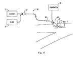
- FIG 1 illustrates one embodiment of a system for causing rotation of the tip 30, the system shown schematically.
- the atherectomy tip 30 of the device 10 is connected to the distal end of the flexible inner shaft 22 (see Figure 3 ) such that rotation of the inner shaft 22 rotates the rotatable tip 30.
- the rotatable shaft 22, with burr or tip 30 at its distalmost end, is electrically powered for high speed rotation to rotate the shaft 22 and tip 30.
- High speed rotation of the shaft 22 likewise rotates tip 30, enabling the tip 30 to break up plaque to treat stenosis of a vessel.
- a motor housing 2, shown schematically, contains a motor mounted therein and a motor shaft (not shown).
- the atherectomy device or catheter 10 is operatively connected to the motor housing 2 such that activation of the motor rotates the inner shaft 22 of the catheter.
- a control knob can be provided to adjust the rotational speed of the shaft 22 and tip 30, and a window can be provided to visually display the speed.
- An advancing mechanism (not shown) can be provided for sliding the shaft 22 and tip 30 a desired distance within the vessel (e.g., about 3-10cm).
- Shaft 22 and tip 30 can be disposable.
- introducer sheath or catheter 24 is inserted through an incision "A" in the patient's leg, and through an incision "B" in the femoral artery "C".
- the shaft 22 and tip 30 are then introduced through the introducer sheath 24 into the femoral artery "C", and advanced to the target artery, e.g., the coronary artery to the treatment obstruction site.
- a guidewire (not shown) extends through the sheath 24 and into the target artery so that the shaft 22 and tip 30 are inserted over the guidewire.
- the system further includes an aspiration source and fluid source, shown schematically, and respectively designated by reference numerals 4 and 6.
- Tubing 8 extends from the aspiration source 4 to the catheter 10, preferably through a side arm of catheter hub 27 for aspiration between an outer wall of the shaft and inner wall of outer tube (member) 20 of catheter 10.
- Tubing 11 extends from the fluid source 6, preferably through a second side arm of hub 27, to communicate with the inner lumen of the shaft 22, in the space (gap) between the guidewire and inner wall of shaft 22.
- the system shown schematically, is identical to the system of Figure 1 , except it has an aspiration source 9 communicating with the introducer sheath 35 via a port or side arm in hub 37 to provide aspiration in the space (gap) between the inner wall of the introducer sheath 35 and the outer wall of outer tube 20 of catheter 10.
- the introducer sheath 35 can extend to a region adjacent the tip or alternatively a sleeve would be inserted through the introducer sheath 24 and advanced over the guidewire.
- the aspiration through the introducer sheath 35 can be the sole source of aspiration or alternatively used in addition to the aspiration through the catheter as in Figure 1 .
- the rotatable (rotating) tip 30 is shown inserted through the femoral artery by way of example as other vessels can be utilized for access, such as the radial artery.
- the tip 30 of the present invention (and other tips described herein) can be used to remove plaque or other obstructions in a variety of vessels such as the coronary artery, the tibial artery, the superficial femoral, popliteal, saphenous vein bypass grafts and instent restenosis.
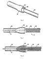
- Tip or burr 30 has a front (distal) portion (section) 40, a rear (proximal) portion (section) 42, and an intermediate portion (section) 44. These portions vary in transverse cross-section as can be appreciated by the Figures.
- the front portion 40 can be defined for convenience as the area starting at the distalmost end 46, terminating at the scalloped region, and forming a bullet-nose configuration.
- the cross-section of the front portion 40 in one embodiment is substantially circular in configuration. Note the term “distal” refers to regions futher from the user and the term "proximal" refers to regions closer to the user.
- Intermediate portion 44 can be considered for convenience as starting at the scalloped portion (proximal of the proximal end of the front portion 40) and terminating at the proximal end of the scalloped region.
- the cross-section of the intermediate portion 44 progressively changes from substantially circular, to an elongated shape having two substantially flat (substantially linear) opposing sidewalls 44a.
- the elongation progressively increases in a first dimension while progressively narrowing in a second dimension.
- the distance between opposing linear walls 44a is less than the distance between opposing arcuate walls 45a, with the distances between linear walls 44a decreasing toward rear section 42.
- Rear portion 42 can be considered to begin, for convenience, at the proximal end of the scalloped region of the intermediate portion 44, and terminate at the proximalmost edge 48 of tip 30.
- the rear portion 42 preferably has the same elongated cross-sectional dimension throughout its length, with substantially linear walls 44a separated by a distance less than the distance between opposing curved walls 45a.
- Rotatable tip 30 is preferably a monolithic piece.
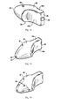
- Tip 30 has a proximal or rear (proximal) opening 32 and a front (distal) opening 34 connected by a lumen.
- the flexible shaft 22 is inserted through rear opening 32 and attached to the tip 30 within lumen 36, however, terminating proximally of the distalmost end 46 of the tip 30 so as to leave a path for high pressure fluid flow.
- a guidewire G can extend through the hollow flexible shaft 22 and through front opening 34 of tip 30 to enable over the wire insertion of the atherectomy tip 30.
- One or more openings 33 could be provided in the tip 30 to enable removal of the plaque as the particles (deposits) can be aspirated through the openings 33 by the aspiration source 4.
- FIGS 14 and 15 illustrate an alternate embodiment of the tip, designated by reference numeral 30', having openings 33' identical to openings 33 of Figure 12 , plus additional openings 50 for aspiration of particles.
- tip 30' is identical to tip 30.
- Tip 30' is shown with the shaft 22 and outer member 20 positioned over a guidewire G in Figure 15 discussed below. Note deposits and particles are used interchangeably herein.
- a scalloped or narrowed section 47 is formed in both sides in the intermediate section 44 of the tip 30 to reduce the profile of the tip 30. These scalloped sections form the aforedescribed opposing substantially linear walls.
- the region of plaque removal is defined by the largest diameter region of the tip since the tip is rotating at high speeds and the plaque is cut or abraded only where the tip comes into contact with it.
- the sheath size required is determined by the largest circumference region of the tip.
- the tip 30 can be introduced into an introducer sheath have an internal diameter slightly less than the largest diameter of the tip, since the sheath has room to deform because of the reduced regions, i.e., the scalloped sections, of the tip 30.
- the rounded symmetrical configuration leaves no room for the sheath to deform so the sheath size must exceed the largest diameter region.
- the tip 30 of the present invention can fit into conventional introducer sheaths having an internal diameter less than the largest outer diameter of the tip 30. This can be achieved by the fact that the tip 30 can deform the internal walls of the introducer sheath 24 as it is inserted, by elongating it in the direction shown in Figures 7 and 8 . If the scalloped walls were not provided, the sheath could not deform because it would be limited by the width of the tip as described below.
- a larger atherectomy tip can be utilized if the atherectomy tip 30 of the present invention is selected instead of the prior art elliptical tip, thereby advantageously increasing the region of plaque removal to create a larger passageway in the vessel.
- longitudinal or elongated circular and oval cutting grooves could be provided to provide a roughened surface to cut or ablate the plaque as the tip is rotated.
- the grooves or indentations can be formed by laser cutting a series of grooves extending longitudinally within the interior of the tip stock. The tip is then ground to remove portions of the outer surface to partially communicate with the grooves, thereby creating indentations forming a roughened surface for contact with the plaque. The resulting formation is a series of elongated cutouts/indentations on the front and intermediate portions and oval shaped cutouts/indentations on the distal and intermediate portions.
- Another way contemplated to create the roughened surface is by blasting, e.g., sandblasting or grit blasting, the tip.
- the tip is held in a fixture and blasted at a certain pressure, thereby removing portions of the outer surface to create a roughened surface.
- Shaft 22 can include a series of threads 25. These threads function as an Archimedes screw, i.e., a screw pump, to remove the particles/deposits dislodged by the tip 30. That is, as the shaft 22 is rotated, the screw's helical surface scoops the deposits and directs the deposits proximally (rearwardly) along the shaft 22. The aspiration in the space between shaft 22 and outer member 20 pulls dislodged particles proximally.
- the Figures show the threads almost abutting the outer member 20 but in preferred embodiments the threads would be spaced further inwardly from the outer member to leave space for rotation and aspiration.
- the system of the present invention includes an aspiration system and a fluid system.
- the aspiration system 4 provides suction through the shaft 22, in the gap 36 between the outer diameter of the shaft 22 and the inner diameter of the outer member (outer tube) 20 of catheter 10 when the aspiration system 4 is activated. Fluid can be pumped at high pressure into the gap between the outer diameter of the guidewire G and the inner diameter of the shaft 22. In this manner, as shown in Figure 9 , fluid injected from fluid source 6 flows through the gap 38 between the inner wall of the lumen of the shaft 22 and the outer wall of the guidewire G.
- FIGS 16A-16C Use of the atherectomy tip of the present invention is illustrated in Figures 16A-16C .
- plaque "P" buildup on the interior wall of the vessel “V” has occluded the passageway through the vessel.
- Tip 30' (or tip 30) is inserted over guidewire G and motorized rotation of flexible rotatable shaft 22 rotates the shaft 22 and attached rotatable tip 30' (or 30) at high speed in the direction of the arrow in Figure 16B to remove plaque which comes into contact with its outer surface.
- High pressure fluid is injected in the direction of the solid arrow in gap 38 between the guidewire G and inner wall of inner shaft 22 to bounce off the internal distal wall of the tip 30' (or 30) and provide a rearward force to particles (deposits) received in the tip.
- Aspiration is provided to aspirate the broken off particles through openings 33' and 50 in the tip and through the gap 39 between the outer wall of the catheter 10 and the inner wall of the introducer sheath 35.
- the fluid flow is designated by the solid arrows and the aspiration is designated by the squiggly arrows in Figure 16C .
- the cut plaque and debris can be removed from the patient's body as the particles are dislodged by the rotating tip 30' (or 30).
Landscapes
- Health & Medical Sciences (AREA)
- Surgery (AREA)
- Life Sciences & Earth Sciences (AREA)
- Medical Informatics (AREA)
- Nuclear Medicine, Radiotherapy & Molecular Imaging (AREA)
- Engineering & Computer Science (AREA)
- Biomedical Technology (AREA)
- Heart & Thoracic Surgery (AREA)
- Molecular Biology (AREA)
- Animal Behavior & Ethology (AREA)
- General Health & Medical Sciences (AREA)
- Public Health (AREA)
- Veterinary Medicine (AREA)
- Vascular Medicine (AREA)
- Orthopedic Medicine & Surgery (AREA)
- Surgical Instruments (AREA)
Applications Claiming Priority (2)
| Application Number | Priority Date | Filing Date | Title |
|---|---|---|---|
| US201461946733P | 2014-03-01 | 2014-03-01 | |
| US14/616,670 US10271869B2 (en) | 2014-03-01 | 2015-02-07 | Atherectomy device |
Publications (2)
| Publication Number | Publication Date |
|---|---|
| EP2913012A1 true EP2913012A1 (de) | 2015-09-02 |
| EP2913012B1 EP2913012B1 (de) | 2019-10-09 |
Family
ID=52573615
Family Applications (1)
| Application Number | Title | Priority Date | Filing Date |
|---|---|---|---|
| EP15155876.4A Active EP2913012B1 (de) | 2014-03-01 | 2015-02-20 | Atherektomievorrichtung |
Country Status (3)
| Country | Link |
|---|---|
| US (2) | US10271869B2 (de) |
| EP (1) | EP2913012B1 (de) |
| JP (1) | JP6612510B2 (de) |
Cited By (7)
| Publication number | Priority date | Publication date | Assignee | Title |
|---|---|---|---|---|
| EP3141201A1 (de) * | 2015-09-13 | 2017-03-15 | Rex Medical, L.P. | Atherektomievorrichtung |
| EP3222228A1 (de) * | 2016-03-26 | 2017-09-27 | Rex Medical, L.P. | Atherektomievorrichtung |
| EP3292827A1 (de) * | 2016-09-13 | 2018-03-14 | Biosense Webster (Israel), Ltd. | Debrider mit mehreren spülungsöffnungen |
| CN110251207A (zh) * | 2019-07-12 | 2019-09-20 | 苏州特普新智能科技有限公司 | 一种外周斑块旋切复合装置 |
| US11426194B2 (en) | 2014-12-27 | 2022-08-30 | Rex Medical L.P. | Atherectomy device |
| US11547434B2 (en) | 2014-12-27 | 2023-01-10 | Rex Medical L.P. | Atherectomy device |
| CN116327272A (zh) * | 2023-03-20 | 2023-06-27 | 深圳微美机器人有限公司 | 取发装置及植发机器人 |
Families Citing this family (19)
| Publication number | Priority date | Publication date | Assignee | Title |
|---|---|---|---|---|
| US10271869B2 (en) | 2014-03-01 | 2019-04-30 | Rex Medical, L.P. | Atherectomy device |
| EP3508148B1 (de) | 2016-08-30 | 2021-06-30 | Terumo Kabushiki Kaisha | Medizinische vorrichtung |
| CN110582242B (zh) | 2017-05-03 | 2023-03-10 | 美敦力瓦斯科尔勒公司 | 组织移除导管 |
| US11690645B2 (en) | 2017-05-03 | 2023-07-04 | Medtronic Vascular, Inc. | Tissue-removing catheter |
| US20230039005A1 (en) * | 2018-02-23 | 2023-02-09 | Efemoral Medical, Inc. | Absorbable intravascular devices for the treatment of venous occlusive disease |
| CN118697424A (zh) | 2018-11-16 | 2024-09-27 | 美敦力瓦斯科尔勒公司 | 组织去除导管 |
| US11819236B2 (en) | 2019-05-17 | 2023-11-21 | Medtronic Vascular, Inc. | Tissue-removing catheter |
| EP3915605A1 (de) * | 2020-05-27 | 2021-12-01 | Medela Holding AG | Fördervorrichtung für körperflüssigkeit |
| CN116367788A (zh) * | 2020-11-02 | 2023-06-30 | 巴德外周血管股份有限公司 | 具有研磨元件的轨道式粥样斑块切除系统 |
| CN112914679B (zh) * | 2021-02-02 | 2022-12-23 | 广东工业大学 | 可径向变形的血栓清除器械 |
| JP2024512790A (ja) | 2021-04-01 | 2024-03-19 | レスネント・エルエルシー | 整形外科用関節鏡検査光学カニューレシステム |
| US12336731B2 (en) * | 2021-10-22 | 2025-06-24 | Gyrus Acmi, Inc. | High speed burr with flex shaft cooling and improved suction |
| EP4447828A1 (de) * | 2021-12-17 | 2024-10-23 | Covidien LP | Aspirationssystem mit einem thrombuszerstörenden inneren element |
| CN114916997B (zh) * | 2022-05-31 | 2025-11-04 | 上海微创旋律医疗科技有限公司 | 旋磨装置及旋磨设备 |
| EP4539754B1 (de) * | 2022-06-15 | 2026-03-11 | Resnent, LLC | Chirurgische vorrichtung mit einem einzigen portal |
| CN115778481A (zh) * | 2022-11-17 | 2023-03-14 | 上海康德莱医疗器械股份有限公司 | 一种切割导丝及血栓抽吸系统 |
| WO2024210884A1 (en) * | 2023-04-03 | 2024-10-10 | Bard Peripheral Vascular, Inc. | Thrombectomy devices and methods |
| CN117122376B (zh) * | 2023-07-03 | 2025-05-16 | 中国人民解放军空军军医大学 | 一种血管斑块旋切刀系统 |
| WO2025076370A1 (en) | 2023-10-05 | 2025-04-10 | Resnent, Llc | Orthopedic arthroscopic optical cannula system |
Citations (14)
| Publication number | Priority date | Publication date | Assignee | Title |
|---|---|---|---|---|
| US4990134A (en) | 1986-01-06 | 1991-02-05 | Heart Technology, Inc. | Transluminal microdissection device |
| US5114399A (en) * | 1990-10-01 | 1992-05-19 | Intramed Laboratories | Surgical device |
| US5217474A (en) | 1991-07-15 | 1993-06-08 | Zacca Nadim M | Expandable tip atherectomy method and apparatus |
| US5632755A (en) * | 1992-11-09 | 1997-05-27 | Endo Vascular Intruments, Inc. | Intra-artery obstruction clearing apparatus and methods |
| US5681336A (en) | 1995-09-07 | 1997-10-28 | Boston Scientific Corporation | Therapeutic device for treating vien graft lesions |
| US5938670A (en) | 1992-10-07 | 1999-08-17 | Scimed Life Systems, Inc. | Ablation devices and methods of use |
| US6015420A (en) | 1997-03-06 | 2000-01-18 | Scimed Life Systems, Inc. | Atherectomy device for reducing damage to vessels and/or in-vivo stents |
| US6096054A (en) | 1998-03-05 | 2000-08-01 | Scimed Life Systems, Inc. | Expandable atherectomy burr and method of ablating an occlusion from a patient's blood vessel |
| WO2002026289A1 (en) * | 2000-09-28 | 2002-04-04 | Beck Robert C | Catheter system |
| US20020099367A1 (en) * | 2001-01-23 | 2002-07-25 | Scimed Life Systems Inc. | Frontal infusion system for intravenous burrs |
| US6572630B1 (en) * | 2000-01-31 | 2003-06-03 | Rex Medical, L.P | Atherectomy device |
| US6676698B2 (en) | 2000-06-26 | 2004-01-13 | Rex Medicol, L.P. | Vascular device with valve for approximating vessel wall |
| NL1034242C2 (nl) * | 2007-02-16 | 2008-08-19 | T M H Beheer B V | Katheter, kathetersysteem en werkwijze voor het intervenieren in een kanaal-vormig orgaan, zoals een bloedbaan. |
| CN102670283A (zh) * | 2012-06-08 | 2012-09-19 | 李广成 | 血肿清除器的碎吸器 |
Family Cites Families (120)
| Publication number | Priority date | Publication date | Assignee | Title |
|---|---|---|---|---|
| US4445509A (en) | 1982-02-04 | 1984-05-01 | Auth David C | Method and apparatus for removal of enclosed abnormal deposits |
| US4957482A (en) | 1988-12-19 | 1990-09-18 | Surgical Systems & Instruments, Inc. | Atherectomy device with a positive pump means |
| US5653696A (en) | 1984-05-14 | 1997-08-05 | Surgical Systems & Instruments, Inc. | Stent unclogging method |
| US4883458A (en) | 1987-02-24 | 1989-11-28 | Surgical Systems & Instruments, Inc. | Atherectomy system and method of using the same |
| US4979939A (en) | 1984-05-14 | 1990-12-25 | Surgical Systems & Instruments, Inc. | Atherectomy system with a guide wire |
| US5306244A (en) | 1984-05-14 | 1994-04-26 | Surgical Systems & Instruments, Inc. | Method of guidewire insertion |
| US5047040A (en) | 1987-11-05 | 1991-09-10 | Devices For Vascular Intervention, Inc. | Atherectomy device and method |
| US5728129A (en) | 1989-02-17 | 1998-03-17 | American Biomed, Inc. | Distal atherectomy catheter |
| US5019089A (en) | 1989-12-07 | 1991-05-28 | Interventional Technologies Inc. | Atherectomy advancing probe and method of use |
| US5273526A (en) * | 1991-06-21 | 1993-12-28 | Lake Region Manufacturing Company, Inc. | Vascular occulusion removal devices and method |
| US6623516B2 (en) | 1992-08-13 | 2003-09-23 | Mark A. Saab | Method for changing the temperature of a selected body region |
| US5287858A (en) | 1992-09-23 | 1994-02-22 | Pilot Cardiovascular Systems, Inc. | Rotational atherectomy guidewire |
| US5356418A (en) | 1992-10-28 | 1994-10-18 | Shturman Cardiology Systems, Inc. | Apparatus and method for rotational atherectomy |
| US5360432A (en) | 1992-10-16 | 1994-11-01 | Shturman Cardiology Systems, Inc. | Abrasive drive shaft device for directional rotational atherectomy |
| US5312427A (en) | 1992-10-16 | 1994-05-17 | Shturman Cardiology Systems, Inc. | Device and method for directional rotational atherectomy |
| US5490859A (en) | 1992-11-13 | 1996-02-13 | Scimed Life Systems, Inc. | Expandable intravascular occlusion material removal devices and methods of use |
| US5794626A (en) | 1994-08-18 | 1998-08-18 | Kieturakis; Maciej J. | Excisional stereotactic apparatus |
| US5584843A (en) | 1994-12-20 | 1996-12-17 | Boston Scientific Corporation | Shaped wire multi-burr rotational ablation device |
| DE59609338D1 (de) | 1995-03-28 | 2002-07-18 | Straub Medical Ag Wangs | Katheter zum ablösen von abnormalen ablagerungen in menschlichen blutgefässen |
| AU713141B2 (en) | 1995-03-28 | 1999-11-25 | Straub Medical Ag | Catheter for detaching abnormal deposits from blood vessels in humans |
| US6569147B1 (en) | 1996-07-26 | 2003-05-27 | Kensey Nash Corporation | Systems and methods of use for delivering beneficial agents for revascularizing stenotic bypass grafts and other occluded blood vessels and for other purposes |
| US6652546B1 (en) | 1996-07-26 | 2003-11-25 | Kensey Nash Corporation | System and method of use for revascularizing stenotic bypass grafts and other occluded blood vessels |
| US5779721A (en) | 1996-07-26 | 1998-07-14 | Kensey Nash Corporation | System and method of use for revascularizing stenotic bypass grafts and other blood vessels |
| US6905505B2 (en) | 1996-07-26 | 2005-06-14 | Kensey Nash Corporation | System and method of use for agent delivery and revascularizing of grafts and vessels |
| US6080170A (en) | 1996-07-26 | 2000-06-27 | Kensey Nash Corporation | System and method of use for revascularizing stenotic bypass grafts and other occluded blood vessels |
| US6830577B2 (en) | 1996-07-26 | 2004-12-14 | Kensey Nash Corporation | System and method of use for treating occluded vessels and diseased tissue |
| US5899915A (en) | 1996-12-02 | 1999-05-04 | Angiotrax, Inc. | Apparatus and method for intraoperatively performing surgery |
| US6183487B1 (en) | 1997-03-06 | 2001-02-06 | Scimed Life Systems, Inc. | Ablation device for reducing damage to vessels and/or in-vivo stents |
| US6090118A (en) | 1998-07-23 | 2000-07-18 | Mcguckin, Jr.; James F. | Rotational thrombectomy apparatus and method with standing wave |
| US7037316B2 (en) | 1997-07-24 | 2006-05-02 | Mcguckin Jr James F | Rotational thrombectomy device |
| US6494890B1 (en) | 1997-08-14 | 2002-12-17 | Shturman Cardiology Systems, Inc. | Eccentric rotational atherectomy device |
| US6132444A (en) | 1997-08-14 | 2000-10-17 | Shturman Cardiology Systems, Inc. | Eccentric drive shaft for atherectomy device and method for manufacture |
| US6077282A (en) | 1997-10-27 | 2000-06-20 | Shturman Cardiology Systems, Inc. | Rotational atherectomy device with exchangeable drive shaft cartridge |
| US6156046A (en) | 1997-11-07 | 2000-12-05 | Prolifix Medical, Inc. | Methods and systems for treating obstructions in a body lumen |
| US5976165A (en) | 1997-12-10 | 1999-11-02 | Scimed Life Systems, Inc. | Rotational ablation device having replaceable screw-on burrs |
| US6824550B1 (en) | 2000-04-06 | 2004-11-30 | Norbon Medical, Inc. | Guidewire for crossing occlusions or stenosis |
| US6146395A (en) | 1998-03-05 | 2000-11-14 | Scimed Life Systems, Inc. | Ablation burr |
| US6482217B1 (en) | 1998-04-10 | 2002-11-19 | Endicor Medical, Inc. | Neuro thrombectomy catheter |
| US6666874B2 (en) | 1998-04-10 | 2003-12-23 | Endicor Medical, Inc. | Rotational atherectomy system with serrated cutting tip |
| US6001112A (en) | 1998-04-10 | 1999-12-14 | Endicor Medical, Inc. | Rotational atherectomy device |
| US6847987B2 (en) * | 1998-09-30 | 2005-01-25 | International Business Machines Corporation | System and method for extending client-server software to additional client platforms for servicing thin clients requests |
| CA2256132A1 (en) | 1998-12-16 | 2000-06-16 | Brian M. Strauss | Rotatable attachment mechanism for attaching a medical obstruction treatment device sub-assembly to a drive motor unit |
| US6113615A (en) | 1999-02-03 | 2000-09-05 | Scimed Life Systems, Inc. | Atherectomy burr including a bias wire |
| US20030125757A1 (en) | 2000-12-20 | 2003-07-03 | Fox Hollow Technologies, Inc. | Debulking catheters and methods |
| US7655016B2 (en) | 1999-09-17 | 2010-02-02 | Covidien | Mechanical pump for removal of fragmented matter and methods of manufacture and use |
| CA2386158A1 (en) | 1999-09-17 | 2001-03-22 | Bacchus Vascular Inc. | Mechanical pump for removal of fragmented matter and methods of manufacture and use |
| US6702830B1 (en) | 1999-09-17 | 2004-03-09 | Bacchus Vascular, Inc. | Mechanical pump for removal of fragmented matter and methods of manufacture and use |
| AU2614901A (en) | 1999-10-22 | 2001-04-30 | Boston Scientific Corporation | Double balloon thrombectomy catheter |
| US8414543B2 (en) | 1999-10-22 | 2013-04-09 | Rex Medical, L.P. | Rotational thrombectomy wire with blocking device |
| US6579299B2 (en) | 2000-01-31 | 2003-06-17 | Rex Medical, L.P. | Atherectomy device |
| US6579298B1 (en) | 2000-02-29 | 2003-06-17 | Scimed Life Systems, Inc. | Method and apparatus for treating vein graft lesions |
| DE60121556T2 (de) | 2000-04-05 | 2007-06-28 | Pathway Medical Technologies, Inc., Redmond | System und Verfahren zum Entfernen von intraluminalem Material |
| US8475484B2 (en) | 2000-04-05 | 2013-07-02 | Medrad, Inc. | Liquid seal assembly for a rotating torque tube |
| US20040243162A1 (en) | 2000-04-05 | 2004-12-02 | Pathway Medical Technologies, Inc. | Interventional catheter assemblies and control systems |
| US7344546B2 (en) | 2000-04-05 | 2008-03-18 | Pathway Medical Technologies | Intralumenal material removal using a cutting device for differential cutting |
| US6497711B1 (en) | 2000-08-16 | 2002-12-24 | Scimed Life Systems, Inc. | Therectomy device having a light weight drive shaft and an imaging device |
| US6569177B1 (en) | 2001-01-19 | 2003-05-27 | Scimed Life Systems, Inc. | Ablation atherectomy burr |
| US6632230B2 (en) | 2001-04-12 | 2003-10-14 | Scimed Life Systems, Inc. | Ablation system with catheter clearing abrasive |
| US6500186B2 (en) | 2001-04-17 | 2002-12-31 | Scimed Life Systems, Inc. | In-stent ablative tool |
| US6443967B1 (en) | 2001-05-03 | 2002-09-03 | Scimed Life Systems, Inc. | Injection moldable feedstock including diamond particles for abrasive applications |
| US6626890B2 (en) | 2001-06-06 | 2003-09-30 | Tony R. Brown | Fat removal device and method |
| US6926725B2 (en) | 2002-04-04 | 2005-08-09 | Rex Medical, L.P. | Thrombectomy device with multi-layered rotational wire |
| US6752630B2 (en) | 2002-04-09 | 2004-06-22 | Patrick L. Roetzer | Dental retractor and fluid control system |
| US8876882B2 (en) | 2003-10-10 | 2014-11-04 | Mark Gelido Barongan | Cutting stent |
| US7799043B2 (en) | 2003-12-01 | 2010-09-21 | Boston Scientific Scimed, Inc. | Cutting balloon having sheathed incising elements |
| MX2009004020A (es) | 2004-03-04 | 2009-04-27 | Cabezal de trabajo de un cateter para aspirar, fragmentar y extraer material extirpable de vasos sanguineos. | |
| US8920402B2 (en) | 2004-04-27 | 2014-12-30 | The Spectranetics Corporation | Thrombectomy and soft debris removal device |
| US7959608B2 (en) | 2004-04-27 | 2011-06-14 | The Spectranetics Corporation | Thrombectomy and soft debris removal device |
| US7819887B2 (en) | 2004-11-17 | 2010-10-26 | Rex Medical, L.P. | Rotational thrombectomy wire |
| GB2426456B (en) | 2005-05-26 | 2010-10-27 | Leonid Shturman | Rotational device with eccentric abrasive element and method of use |
| GB2426458A (en) | 2005-05-26 | 2006-11-29 | Leonid Shturman | Atherectomy device |
| US8628549B2 (en) | 2006-06-30 | 2014-01-14 | Atheromed, Inc. | Atherectomy devices, systems, and methods |
| US20080045986A1 (en) * | 2006-06-30 | 2008-02-21 | Atheromed, Inc. | Atherectomy devices and methods |
| US20080004645A1 (en) | 2006-06-30 | 2008-01-03 | Atheromed, Inc. | Atherectomy devices and methods |
| US8361094B2 (en) | 2006-06-30 | 2013-01-29 | Atheromed, Inc. | Atherectomy devices and methods |
| US8007506B2 (en) | 2006-06-30 | 2011-08-30 | Atheromed, Inc. | Atherectomy devices and methods |
| GB0613981D0 (de) | 2006-07-13 | 2006-08-23 | Shturman Leonid | |
| US8597313B2 (en) | 2007-06-11 | 2013-12-03 | Cardiovascular Systems, Inc. | Eccentric abrading head for high-speed rotational atherectomy devices |
| WO2008155759A2 (en) | 2007-06-21 | 2008-12-24 | Ariomedica Ltd. | Infusion and suction configuration in an atherectomy system |
| US8439937B2 (en) | 2007-06-25 | 2013-05-14 | Cardiovascular Systems, Inc. | System, apparatus and method for opening an occluded lesion |
| US8236016B2 (en) | 2007-10-22 | 2012-08-07 | Atheromed, Inc. | Atherectomy devices and methods |
| US8348965B2 (en) | 2007-10-23 | 2013-01-08 | Cardiovascular Systems, Inc. | Rotational atherectomy device with counterweighting |
| US8551128B2 (en) | 2007-12-06 | 2013-10-08 | Cardiovascular Systems, Inc. | Rotational atherectomy device with pre-curved drive shaft |
| US8579851B2 (en) | 2007-12-20 | 2013-11-12 | Bausch & Lomb Incorporated | Surgical system having means for isolating vacuum pump |
| US8062316B2 (en) | 2008-04-23 | 2011-11-22 | Avinger, Inc. | Catheter system and method for boring through blocked vascular passages |
| US8758377B2 (en) | 2008-05-30 | 2014-06-24 | Cardiovascular Systems, Inc. | Eccentric abrading and cutting head for high-speed rotational atherectomy devices |
| US8702735B2 (en) | 2008-05-30 | 2014-04-22 | Cardiovascular Systems, Inc. | Eccentric abrading element for high-speed rotational atherectomy devices |
| US9055966B2 (en) | 2008-05-30 | 2015-06-16 | Cardiovascular Systems, Inc. | Eccentric abrading and cutting head for high-speed rotational atherectomy devices |
| CH699981A2 (de) | 2008-11-27 | 2010-05-31 | Straub Medical Ag | Katheter zum Ansaugen, Fragmentieren und Hinausbefördern von entfernbarem Material aus Blutgefässen. |
| US8795303B2 (en) | 2009-02-02 | 2014-08-05 | Cardiovascular Systems, Inc. | Multi-material abrading head for atherectomy devices having laterally displaced center of mass |
| US8628550B2 (en) | 2009-02-19 | 2014-01-14 | Cardiovascular Systems, Inc. | Rotational atherectomy segmented abrading head and method to improve abrading efficiency |
| GB0905751D0 (en) | 2009-04-03 | 2009-05-20 | Shturman Leonid | Rotational atherectomy device with distal embolic protection and method of use |
| US8632557B2 (en) | 2009-05-12 | 2014-01-21 | Cardiovascular Systems, Inc. | Rotational atherectomy device and method to improve abrading efficiency |
| BRPI1010595A2 (pt) | 2009-05-14 | 2017-05-16 | Tyco Healthcare | cateteres de aterectomia facilmente limpaveis e metodos para uso |
| US8795304B2 (en) | 2009-06-18 | 2014-08-05 | Cardiovascular Systems, Inc. | Atherectomy device, system and method having a bi-directional distal expandable ablation element |
| US8388582B2 (en) | 2009-08-12 | 2013-03-05 | Medrad, Inc. | Systems and methods for operating interventional catheters using a common operating console and adaptive interface components |
| US9050126B2 (en) | 2010-02-26 | 2015-06-09 | Cardiovascular Systems, Inc. | Rotational atherectomy device with electric motor |
| US8273097B2 (en) | 2010-04-30 | 2012-09-25 | Medtronic Xomed, Inc. | Powered surgical tissue cutting instrument having an irrigation system |
| US20130103046A1 (en) | 2010-05-04 | 2013-04-25 | Samuel Shiber | Rotary catheter for removing obstructions from bodily vessels |
| US8764779B2 (en) | 2010-05-13 | 2014-07-01 | Rex Medical, L.P. | Rotational thrombectomy wire |
| US9023070B2 (en) | 2010-05-13 | 2015-05-05 | Rex Medical, L.P. | Rotational thrombectomy wire coupler |
| US8663259B2 (en) | 2010-05-13 | 2014-03-04 | Rex Medical L.P. | Rotational thrombectomy wire |
| US9585667B2 (en) | 2010-11-15 | 2017-03-07 | Vascular Insights Llc | Sclerotherapy catheter with lumen having wire rotated by motor and simultaneous withdrawal from vein |
| US20120211542A1 (en) | 2011-02-23 | 2012-08-23 | Tyco Healthcare Group I.P | Controlled tissue compression systems and methods |
| ES2657019T3 (es) | 2011-08-17 | 2018-03-01 | Samuel Shiber | Catéter giratorio adaptativo para abrir vasos corporales obstruidos |
| US9345511B2 (en) | 2011-10-13 | 2016-05-24 | Atheromed, Inc. | Atherectomy apparatus, systems and methods |
| US9033895B2 (en) | 2011-12-02 | 2015-05-19 | Interscope, Inc. | Endoscope including an torque generation component or torque delivery component disposed within an insertable portion of the endoscope and a surgical cutting assembly insertable within the endoscope |
| US8882680B2 (en) | 2011-12-02 | 2014-11-11 | Interscope, Inc. | Insertable endoscopic instrument for tissue removal |
| US9033864B2 (en) | 2011-12-02 | 2015-05-19 | Interscope, Inc. | Endoscope including a torque generation component or torque delivery component disposed within an insertable portion of the endoscope and a surgical cutting assembly insertable within the endoscope |
| US9028424B2 (en) | 2011-12-02 | 2015-05-12 | Interscope, Inc. | Endoscope including a torque generation component or torque delivery component disposed within an insertable portion of the endoscope and a surgical cutting assembly insertable within the endoscope |
| KR20130080909A (ko) | 2012-01-06 | 2013-07-16 | 삼성전자주식회사 | 수술 로봇 및 그 제어 방법 |
| KR102122219B1 (ko) | 2012-03-13 | 2020-06-12 | 메드트로닉 좀드 인코퍼레이티드 | 전동식 로타리형 핸드피스를 포함하는 수술용 시스템 |
| US20130253552A1 (en) | 2012-03-20 | 2013-09-26 | Cardiovascular Systems, Inc. | Controller for an atherectomy device |
| US9539022B2 (en) | 2012-11-28 | 2017-01-10 | Microvention, Inc. | Matter conveyance system |
| JP6391910B2 (ja) | 2012-12-14 | 2018-09-19 | 株式会社グッドマン | 吸引カテーテル |
| JP6087020B2 (ja) | 2013-03-12 | 2017-03-01 | ボストン サイエンティフィック サイムド,インコーポレイテッドBoston Scientific Scimed,Inc. | 粥腫切除装置 |
| US9848907B2 (en) | 2013-03-15 | 2017-12-26 | Cardiovascular Systems, Inc. | Rotational atherectomy device with biasing clutch |
| US20140330286A1 (en) | 2013-04-25 | 2014-11-06 | Michael P. Wallace | Methods and Devices for Removing Obstructing Material From the Human Body |
| US10271869B2 (en) | 2014-03-01 | 2019-04-30 | Rex Medical, L.P. | Atherectomy device |
| US10405924B2 (en) | 2014-05-30 | 2019-09-10 | The Spectranetics Corporation | System and method of ablative cutting and vacuum aspiration through primary orifice and auxiliary side port |
-
2015
- 2015-02-07 US US14/616,670 patent/US10271869B2/en active Active
- 2015-02-20 EP EP15155876.4A patent/EP2913012B1/de active Active
- 2015-02-27 JP JP2015039062A patent/JP6612510B2/ja active Active
-
2019
- 2019-04-13 US US16/383,602 patent/US10751083B2/en active Active
Patent Citations (15)
| Publication number | Priority date | Publication date | Assignee | Title |
|---|---|---|---|---|
| US4990134A (en) | 1986-01-06 | 1991-02-05 | Heart Technology, Inc. | Transluminal microdissection device |
| US4990134B1 (en) | 1986-01-06 | 1996-11-05 | Heart Techn Inc | Transluminal microdissection device |
| US5114399A (en) * | 1990-10-01 | 1992-05-19 | Intramed Laboratories | Surgical device |
| US5217474A (en) | 1991-07-15 | 1993-06-08 | Zacca Nadim M | Expandable tip atherectomy method and apparatus |
| US5938670A (en) | 1992-10-07 | 1999-08-17 | Scimed Life Systems, Inc. | Ablation devices and methods of use |
| US5632755A (en) * | 1992-11-09 | 1997-05-27 | Endo Vascular Intruments, Inc. | Intra-artery obstruction clearing apparatus and methods |
| US5681336A (en) | 1995-09-07 | 1997-10-28 | Boston Scientific Corporation | Therapeutic device for treating vien graft lesions |
| US6015420A (en) | 1997-03-06 | 2000-01-18 | Scimed Life Systems, Inc. | Atherectomy device for reducing damage to vessels and/or in-vivo stents |
| US6096054A (en) | 1998-03-05 | 2000-08-01 | Scimed Life Systems, Inc. | Expandable atherectomy burr and method of ablating an occlusion from a patient's blood vessel |
| US6572630B1 (en) * | 2000-01-31 | 2003-06-03 | Rex Medical, L.P | Atherectomy device |
| US6676698B2 (en) | 2000-06-26 | 2004-01-13 | Rex Medicol, L.P. | Vascular device with valve for approximating vessel wall |
| WO2002026289A1 (en) * | 2000-09-28 | 2002-04-04 | Beck Robert C | Catheter system |
| US20020099367A1 (en) * | 2001-01-23 | 2002-07-25 | Scimed Life Systems Inc. | Frontal infusion system for intravenous burrs |
| NL1034242C2 (nl) * | 2007-02-16 | 2008-08-19 | T M H Beheer B V | Katheter, kathetersysteem en werkwijze voor het intervenieren in een kanaal-vormig orgaan, zoals een bloedbaan. |
| CN102670283A (zh) * | 2012-06-08 | 2012-09-19 | 李广成 | 血肿清除器的碎吸器 |
Cited By (15)
| Publication number | Priority date | Publication date | Assignee | Title |
|---|---|---|---|---|
| US11426194B2 (en) | 2014-12-27 | 2022-08-30 | Rex Medical L.P. | Atherectomy device |
| US11547434B2 (en) | 2014-12-27 | 2023-01-10 | Rex Medical L.P. | Atherectomy device |
| EP3141201A1 (de) * | 2015-09-13 | 2017-03-15 | Rex Medical, L.P. | Atherektomievorrichtung |
| US12274822B2 (en) | 2015-09-13 | 2025-04-15 | Rex Medical, L.P. | Atherectomy device |
| US11253292B2 (en) | 2015-09-13 | 2022-02-22 | Rex Medical, L.P. | Atherectomy device |
| EP3222228A1 (de) * | 2016-03-26 | 2017-09-27 | Rex Medical, L.P. | Atherektomievorrichtung |
| CN107224313A (zh) * | 2016-03-26 | 2017-10-03 | 雷克斯医疗公司 | 斑块去除装置 |
| US12478392B2 (en) | 2016-03-26 | 2025-11-25 | Rex Medical, L.P. | Atherectomy device |
| US11864780B2 (en) | 2016-03-26 | 2024-01-09 | Rex Medical, L.P. | Atherectomy device |
| EP3292827A1 (de) * | 2016-09-13 | 2018-03-14 | Biosense Webster (Israel), Ltd. | Debrider mit mehreren spülungsöffnungen |
| CN107812264B (zh) * | 2016-09-13 | 2022-04-15 | 韦伯斯特生物官能(以色列)有限公司 | 具有多个冲刷孔口的清创器 |
| US10709472B2 (en) | 2016-09-13 | 2020-07-14 | Biosense Webster (Israel) Ltd. | Debrider with multiple flushing orifices |
| CN107812264A (zh) * | 2016-09-13 | 2018-03-20 | 韦伯斯特生物官能(以色列)有限公司 | 具有多个冲刷孔口的清创器 |
| CN110251207A (zh) * | 2019-07-12 | 2019-09-20 | 苏州特普新智能科技有限公司 | 一种外周斑块旋切复合装置 |
| CN116327272A (zh) * | 2023-03-20 | 2023-06-27 | 深圳微美机器人有限公司 | 取发装置及植发机器人 |
Also Published As
| Publication number | Publication date |
|---|---|
| EP2913012B1 (de) | 2019-10-09 |
| US10751083B2 (en) | 2020-08-25 |
| US10271869B2 (en) | 2019-04-30 |
| JP2015164529A (ja) | 2015-09-17 |
| JP6612510B2 (ja) | 2019-11-27 |
| US20190239921A1 (en) | 2019-08-08 |
| US20150245851A1 (en) | 2015-09-03 |
Similar Documents
| Publication | Publication Date | Title |
|---|---|---|
| US10751083B2 (en) | Atherectomy device | |
| US12274822B2 (en) | Atherectomy device | |
| US12478392B2 (en) | Atherectomy device | |
| US20230270463A1 (en) | Atherectomy device | |
| US20220401122A1 (en) | Atherectomy device | |
| US6579299B2 (en) | Atherectomy device | |
| US6569177B1 (en) | Ablation atherectomy burr | |
| US10357275B2 (en) | Dual-basket self-centering rotational device for treatment of arterial occlusive disease with infinitely adjustable cutting size | |
| EP3037050B1 (de) | Atherektomievorrichtung |
Legal Events
| Date | Code | Title | Description |
|---|---|---|---|
| PUAI | Public reference made under article 153(3) epc to a published international application that has entered the european phase |
Free format text: ORIGINAL CODE: 0009012 |
|
| AK | Designated contracting states |
Kind code of ref document: A1 Designated state(s): AL AT BE BG CH CY CZ DE DK EE ES FI FR GB GR HR HU IE IS IT LI LT LU LV MC MK MT NL NO PL PT RO RS SE SI SK SM TR |
|
| AX | Request for extension of the european patent |
Extension state: BA ME |
|
| 17P | Request for examination filed |
Effective date: 20160216 |
|
| RBV | Designated contracting states (corrected) |
Designated state(s): AL AT BE BG CH CY CZ DE DK EE ES FI FR GB GR HR HU IE IS IT LI LT LU LV MC MK MT NL NO PL PT RO RS SE SI SK SM TR |
|
| STAA | Information on the status of an ep patent application or granted ep patent |
Free format text: STATUS: EXAMINATION IS IN PROGRESS |
|
| 17Q | First examination report despatched |
Effective date: 20180514 |
|
| GRAP | Despatch of communication of intention to grant a patent |
Free format text: ORIGINAL CODE: EPIDOSNIGR1 |
|
| STAA | Information on the status of an ep patent application or granted ep patent |
Free format text: STATUS: GRANT OF PATENT IS INTENDED |
|
| INTG | Intention to grant announced |
Effective date: 20190510 |
|
| GRAS | Grant fee paid |
Free format text: ORIGINAL CODE: EPIDOSNIGR3 |
|
| GRAA | (expected) grant |
Free format text: ORIGINAL CODE: 0009210 |
|
| STAA | Information on the status of an ep patent application or granted ep patent |
Free format text: STATUS: THE PATENT HAS BEEN GRANTED |
|
| AK | Designated contracting states |
Kind code of ref document: B1 Designated state(s): AL AT BE BG CH CY CZ DE DK EE ES FI FR GB GR HR HU IE IS IT LI LT LU LV MC MK MT NL NO PL PT RO RS SE SI SK SM TR |
|
| REG | Reference to a national code |
Ref country code: GB Ref legal event code: FG4D |
|
| REG | Reference to a national code |
Ref country code: CH Ref legal event code: EP |
|
| REG | Reference to a national code |
Ref country code: IE Ref legal event code: FG4D |
|
| REG | Reference to a national code |
Ref country code: DE Ref legal event code: R096 Ref document number: 602015039338 Country of ref document: DE |
|
| REG | Reference to a national code |
Ref country code: AT Ref legal event code: REF Ref document number: 1187882 Country of ref document: AT Kind code of ref document: T Effective date: 20191115 |
|
| REG | Reference to a national code |
Ref country code: NL Ref legal event code: MP Effective date: 20191009 |
|
| REG | Reference to a national code |
Ref country code: LT Ref legal event code: MG4D |
|
| REG | Reference to a national code |
Ref country code: AT Ref legal event code: MK05 Ref document number: 1187882 Country of ref document: AT Kind code of ref document: T Effective date: 20191009 |
|
| PG25 | Lapsed in a contracting state [announced via postgrant information from national office to epo] |
Ref country code: GR Free format text: LAPSE BECAUSE OF FAILURE TO SUBMIT A TRANSLATION OF THE DESCRIPTION OR TO PAY THE FEE WITHIN THE PRESCRIBED TIME-LIMIT Effective date: 20200110 Ref country code: FI Free format text: LAPSE BECAUSE OF FAILURE TO SUBMIT A TRANSLATION OF THE DESCRIPTION OR TO PAY THE FEE WITHIN THE PRESCRIBED TIME-LIMIT Effective date: 20191009 Ref country code: BG Free format text: LAPSE BECAUSE OF FAILURE TO SUBMIT A TRANSLATION OF THE DESCRIPTION OR TO PAY THE FEE WITHIN THE PRESCRIBED TIME-LIMIT Effective date: 20200109 Ref country code: LV Free format text: LAPSE BECAUSE OF FAILURE TO SUBMIT A TRANSLATION OF THE DESCRIPTION OR TO PAY THE FEE WITHIN THE PRESCRIBED TIME-LIMIT Effective date: 20191009 Ref country code: SE Free format text: LAPSE BECAUSE OF FAILURE TO SUBMIT A TRANSLATION OF THE DESCRIPTION OR TO PAY THE FEE WITHIN THE PRESCRIBED TIME-LIMIT Effective date: 20191009 Ref country code: LT Free format text: LAPSE BECAUSE OF FAILURE TO SUBMIT A TRANSLATION OF THE DESCRIPTION OR TO PAY THE FEE WITHIN THE PRESCRIBED TIME-LIMIT Effective date: 20191009 Ref country code: PL Free format text: LAPSE BECAUSE OF FAILURE TO SUBMIT A TRANSLATION OF THE DESCRIPTION OR TO PAY THE FEE WITHIN THE PRESCRIBED TIME-LIMIT Effective date: 20191009 Ref country code: NO Free format text: LAPSE BECAUSE OF FAILURE TO SUBMIT A TRANSLATION OF THE DESCRIPTION OR TO PAY THE FEE WITHIN THE PRESCRIBED TIME-LIMIT Effective date: 20200109 Ref country code: AT Free format text: LAPSE BECAUSE OF FAILURE TO SUBMIT A TRANSLATION OF THE DESCRIPTION OR TO PAY THE FEE WITHIN THE PRESCRIBED TIME-LIMIT Effective date: 20191009 Ref country code: PT Free format text: LAPSE BECAUSE OF FAILURE TO SUBMIT A TRANSLATION OF THE DESCRIPTION OR TO PAY THE FEE WITHIN THE PRESCRIBED TIME-LIMIT Effective date: 20200210 Ref country code: ES Free format text: LAPSE BECAUSE OF FAILURE TO SUBMIT A TRANSLATION OF THE DESCRIPTION OR TO PAY THE FEE WITHIN THE PRESCRIBED TIME-LIMIT Effective date: 20191009 Ref country code: NL Free format text: LAPSE BECAUSE OF FAILURE TO SUBMIT A TRANSLATION OF THE DESCRIPTION OR TO PAY THE FEE WITHIN THE PRESCRIBED TIME-LIMIT Effective date: 20191009 |
|
| PG25 | Lapsed in a contracting state [announced via postgrant information from national office to epo] |
Ref country code: IS Free format text: LAPSE BECAUSE OF FAILURE TO SUBMIT A TRANSLATION OF THE DESCRIPTION OR TO PAY THE FEE WITHIN THE PRESCRIBED TIME-LIMIT Effective date: 20200224 Ref country code: HR Free format text: LAPSE BECAUSE OF FAILURE TO SUBMIT A TRANSLATION OF THE DESCRIPTION OR TO PAY THE FEE WITHIN THE PRESCRIBED TIME-LIMIT Effective date: 20191009 Ref country code: RS Free format text: LAPSE BECAUSE OF FAILURE TO SUBMIT A TRANSLATION OF THE DESCRIPTION OR TO PAY THE FEE WITHIN THE PRESCRIBED TIME-LIMIT Effective date: 20191009 |
|
| PG25 | Lapsed in a contracting state [announced via postgrant information from national office to epo] |
Ref country code: AL Free format text: LAPSE BECAUSE OF FAILURE TO SUBMIT A TRANSLATION OF THE DESCRIPTION OR TO PAY THE FEE WITHIN THE PRESCRIBED TIME-LIMIT Effective date: 20191009 |
|
| REG | Reference to a national code |
Ref country code: DE Ref legal event code: R097 Ref document number: 602015039338 Country of ref document: DE |
|
| PG2D | Information on lapse in contracting state deleted |
Ref country code: IS |
|
| PG25 | Lapsed in a contracting state [announced via postgrant information from national office to epo] |
Ref country code: RO Free format text: LAPSE BECAUSE OF FAILURE TO SUBMIT A TRANSLATION OF THE DESCRIPTION OR TO PAY THE FEE WITHIN THE PRESCRIBED TIME-LIMIT Effective date: 20191009 Ref country code: DK Free format text: LAPSE BECAUSE OF FAILURE TO SUBMIT A TRANSLATION OF THE DESCRIPTION OR TO PAY THE FEE WITHIN THE PRESCRIBED TIME-LIMIT Effective date: 20191009 Ref country code: EE Free format text: LAPSE BECAUSE OF FAILURE TO SUBMIT A TRANSLATION OF THE DESCRIPTION OR TO PAY THE FEE WITHIN THE PRESCRIBED TIME-LIMIT Effective date: 20191009 Ref country code: CZ Free format text: LAPSE BECAUSE OF FAILURE TO SUBMIT A TRANSLATION OF THE DESCRIPTION OR TO PAY THE FEE WITHIN THE PRESCRIBED TIME-LIMIT Effective date: 20191009 Ref country code: IS Free format text: LAPSE BECAUSE OF FAILURE TO SUBMIT A TRANSLATION OF THE DESCRIPTION OR TO PAY THE FEE WITHIN THE PRESCRIBED TIME-LIMIT Effective date: 20200209 |
|
| PLBE | No opposition filed within time limit |
Free format text: ORIGINAL CODE: 0009261 |
|
| STAA | Information on the status of an ep patent application or granted ep patent |
Free format text: STATUS: NO OPPOSITION FILED WITHIN TIME LIMIT |
|
| PG25 | Lapsed in a contracting state [announced via postgrant information from national office to epo] |
Ref country code: IT Free format text: LAPSE BECAUSE OF FAILURE TO SUBMIT A TRANSLATION OF THE DESCRIPTION OR TO PAY THE FEE WITHIN THE PRESCRIBED TIME-LIMIT Effective date: 20191009 Ref country code: SM Free format text: LAPSE BECAUSE OF FAILURE TO SUBMIT A TRANSLATION OF THE DESCRIPTION OR TO PAY THE FEE WITHIN THE PRESCRIBED TIME-LIMIT Effective date: 20191009 Ref country code: SK Free format text: LAPSE BECAUSE OF FAILURE TO SUBMIT A TRANSLATION OF THE DESCRIPTION OR TO PAY THE FEE WITHIN THE PRESCRIBED TIME-LIMIT Effective date: 20191009 |
|
| 26N | No opposition filed |
Effective date: 20200710 |
|
| REG | Reference to a national code |
Ref country code: CH Ref legal event code: PL |
|
| REG | Reference to a national code |
Ref country code: BE Ref legal event code: MM Effective date: 20200229 |
|
| PG25 | Lapsed in a contracting state [announced via postgrant information from national office to epo] |
Ref country code: MC Free format text: LAPSE BECAUSE OF FAILURE TO SUBMIT A TRANSLATION OF THE DESCRIPTION OR TO PAY THE FEE WITHIN THE PRESCRIBED TIME-LIMIT Effective date: 20191009 Ref country code: LU Free format text: LAPSE BECAUSE OF NON-PAYMENT OF DUE FEES Effective date: 20200220 |
|
| PG25 | Lapsed in a contracting state [announced via postgrant information from national office to epo] |
Ref country code: LI Free format text: LAPSE BECAUSE OF NON-PAYMENT OF DUE FEES Effective date: 20200229 Ref country code: CH Free format text: LAPSE BECAUSE OF NON-PAYMENT OF DUE FEES Effective date: 20200229 Ref country code: SI Free format text: LAPSE BECAUSE OF FAILURE TO SUBMIT A TRANSLATION OF THE DESCRIPTION OR TO PAY THE FEE WITHIN THE PRESCRIBED TIME-LIMIT Effective date: 20191009 |
|
| PG25 | Lapsed in a contracting state [announced via postgrant information from national office to epo] |
Ref country code: IE Free format text: LAPSE BECAUSE OF NON-PAYMENT OF DUE FEES Effective date: 20200220 |
|
| PG25 | Lapsed in a contracting state [announced via postgrant information from national office to epo] |
Ref country code: BE Free format text: LAPSE BECAUSE OF NON-PAYMENT OF DUE FEES Effective date: 20200229 |
|
| PG25 | Lapsed in a contracting state [announced via postgrant information from national office to epo] |
Ref country code: TR Free format text: LAPSE BECAUSE OF FAILURE TO SUBMIT A TRANSLATION OF THE DESCRIPTION OR TO PAY THE FEE WITHIN THE PRESCRIBED TIME-LIMIT Effective date: 20191009 Ref country code: MT Free format text: LAPSE BECAUSE OF FAILURE TO SUBMIT A TRANSLATION OF THE DESCRIPTION OR TO PAY THE FEE WITHIN THE PRESCRIBED TIME-LIMIT Effective date: 20191009 Ref country code: CY Free format text: LAPSE BECAUSE OF FAILURE TO SUBMIT A TRANSLATION OF THE DESCRIPTION OR TO PAY THE FEE WITHIN THE PRESCRIBED TIME-LIMIT Effective date: 20191009 |
|
| PG25 | Lapsed in a contracting state [announced via postgrant information from national office to epo] |
Ref country code: MK Free format text: LAPSE BECAUSE OF FAILURE TO SUBMIT A TRANSLATION OF THE DESCRIPTION OR TO PAY THE FEE WITHIN THE PRESCRIBED TIME-LIMIT Effective date: 20191009 |
|
| PGFP | Annual fee paid to national office [announced via postgrant information from national office to epo] |
Ref country code: GB Payment date: 20260206 Year of fee payment: 12 |
|
| PGFP | Annual fee paid to national office [announced via postgrant information from national office to epo] |
Ref country code: DE Payment date: 20260206 Year of fee payment: 12 |
|
| PGFP | Annual fee paid to national office [announced via postgrant information from national office to epo] |
Ref country code: FR Payment date: 20260219 Year of fee payment: 12 |